
Create successful ePaper yourself
Turn your PDF publications into a flip-book with our unique Google optimized e-Paper software.
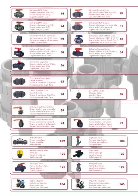
GENERAL SELECTION CRITERIAcritères généraux de choixCRITERIO GENERALE DI SCELTAAllgemeine Auswahlkriterien• The medium transported basically determines theselection of valves.• Pressure and temperature are important criteria.• The valve best suited for a particular pressure andtemperature can be determined from the technicaldata of the respective valve.• The question as to which material will dependon the temperature and chemical resistance of themedium transported.• Selection of the material for the valve seals shouldbe done by taking our chemical resistance chart intoaccount.• A la base, la sélection de la vanne est déterminéepar l’élément transporté.• Il est important de tenir compte de la pression et dela température.• La vanne appropriée est déterminée par chaquepression/température moyennant ses caractéristiquestechniques.• Le matériau choisi est déterminé par la températureet la résistance chimique de l’élément transporté.• Pour sélectionner le matériau de la vanne et dessièges, se référer au tableau de résistances chimiques.• Generalmente, la scelta della valvola viene fatta infunzione della sostanza trasportata.• Importante tenere in conto la pressione e latemperatura.• Si risale alla valvola adeguata per ogni pressione/temperatura mediante le sue caratteristiche tecniche.• Il materiale scelto è in funzione della temperatura edella resistenza chimica al passaggio della sostanzatrasportata.• Per la scelta del materiale del corpo e delleguarnizioni della valvola, tenere in conto la tabelladelle resistenze chimiche.• Grundsätzlich hängt die Wahl des Ventils vomDurchflussmedium ab.• Wichtig Druck und Temperatur berücksichtigen.• Für jede Druckstufe und jeden Temperaturbereichgibt es das passende Ventil entsprechend seinertechnischen Merkmale.• Der geeignete Werkstoff wird durch Temperatur undchemische Beständigkeit des zu transportierendenMediums vorgegeben.• Zur Wahl des Ventilwerkstoffes und der geeignetenKugelsitzdichtungen die Beständigkeitstabelle zuRate ziehen.Concept&typical applicationConceptetapplications typiquesConcepto Concettoeyapplicazioni aplicaciones tipiche típicasKonzept Conceitound etypische aplicações Einsatzbereiche• It controls flow by means of a rotating ball witha hole through it that allows straight-through flowin the open position.• Shuts off flow when the ball is rotated 90º toblock the flow passage.• It is used for on-off and some throttlingservices.> see also Selecting ball valves• Il contrôle le passage du fluide au moyen d’unboisseau rotatif traversée par un trou, en positionouvert, le fluide passe par l’intermédiaire du trou.• Il retient le fluide quand le boisseau est tournéà 90º pour bloquer son passage.• Il est utilisé pour des applications ouvert-ferméet pour certains régulateurs.> voir Sélection de robinets à boisseau• Controlla il passaggio del fluido medianteuna sfera cava rotante attorno ad un perno. Inposizione aperta, il fluido passa attraverso il forodella sfera.• Trattiene il fluido quando la sfera è ruotatadi 90º.• Viene impiegata per applicazioni di apertura- chiusura e in alcuni casi per la parzializzazione.> vedere Scelta delle valvole a sfera• Den Durchfluss ermöglicht die mit einerÖffnung versehene rotierende Kugel. Beigeöffneter Position tritt die Flüssigkeit durch diesehindurch.• Soll der Durchfluss gestoppt werden, wird dieKugel um 90° gedreht.• Einsatz bei Applikationen zum Öffnen bzw.Schließen oder bei Durchflussdrosselung.> Siehe Wahl des Kugelhahn• Valves with automatic operation.• It operates without the need for externalcontrols.• Its operation depends on the direction of theflow and system pressure.• Their main function is to allow the passage ofthe fluid only in one direction, allowing to workwithout fluid in the other direction, or avoidingundesired situtations of draining in the line.> see also Selecting check valves• Ce sont des clapets d’actionnementautomatique.• Ils fonctionnent sans contrôles externes.• Pour leur fonctionnement, ils dépendent dusens de la circulation ou des pressions dans lessystèmes de tube.• Leur principale fonction est de permettrele passage du fluide dans un seul sens del’installation permettant ainsi de travailler sansfluide dans l’autre sens ou d’éviter des situationsde vides non souhaités de la ligne.> voir Sélection de clapets anti-retour• Sono valvole ad operatività automatica.• Funzionano senza controlli esterni.• Il loro funzionamento dipende dal sensodi circolazione o dalla pressione nel sistemaidraulico.• La loro principale funzione è permettereil passaggio del fluido in un solo versodell’impianto, permettendo di lavorare senzafluido nell’altra direzione o evitare situazioniindesiderate di vuoto nella linea.> vedere Scelta delle valvole di nonritorno• Kugelhähne mit Automatik.• Sie funktionieren ohne Kontrolle von außen.• Ihre Funktionsweise ist abhängig von derStrömungsrichtung oder der Drücke imRohrsystem.• Ihre Hauptfunktion besteht darin, denLeitungsdurchfluss in eine Richtung und einArbeiten ohne Flüssigkeit zu ermöglichenoder eine unerwünschte Leitungsentleerung zuvermeiden.> Siehe Wahl des Rückschlagventile• Controls flow by using a circular disk or vanewith its pivot axis at right angles to the directionof flow in the pipe.• Requires a minimum of space.• Is used both for on-off and throttling services.> see also Selecting butterfly valves• Contrôlent le passage du fluide en utilisantun disque circulaire pivotant sur son axe centralpour prendre la direction du fluide.• Utilise un minimum d’espace.• Elle est utilisée pour des applications d’ouvertferméet de contrôle.> voir Sélection de vannes papillon• Controllano il passaggio del fluido tramite undisco circolare che ruota attorno ad un pernocentrale.• Richiedono uno spazio di installazione ridotto.• Sono usate per impieghi di apertura - chiusurae di regolazione.> vedere Scelta delle valvole a farfalla• Sie regeln den Durchfluss mit Hilfe einerrunden Scheibe. Diese dreht sich um dieHauptachse, um die Fließrichtung zu bestimmen.• Geringer Platzbedarf.• Einsatz zur Öffnen- und Schließenapplikationsowie Durchflussdrosselung.> Siehe Wahl des AbsperrklappenElectrically or pneumatically actuated valvesautomate flow control, offering several advantagesover manual valves, in cases like:• Remote location of the valves.• Information about the valve position (openclosed)is needed at all times.• Significant torque.• Synchronized operations, which make itimpossible to operate different valves at thesame time.• Reliability/repetitive operations: to avoid thepossibility of negligences.• Positioning (modulation).• Facility of use.• Security: to avoid undesired operations.> see also Selecting actuated valves• Operated by pipeline pressure or by externalpressure (which is equal to the pipeline pressure).• The reinforced rubber diaphragm seals thewater passage when the line pressure reaches thevalve’s control chamber.• Relieving the pressure from the controlchamber causes the valve to open.• The valve’s only moving part is its diaphragm:no shaft, seals, or bearings are located within thewater passage.• Valve can be supplied in different versions witha wide range of control functions.Les actionneurs électrique ou pneumatiquecontrôlent automatiquement le fluide et offrentcertains avantages:• Localisation à distance des vannes à actionner.• Nécessité de disposer d’information sur laposition des vannes à tout moment.• Couple significatif.• Fonctions simultanées: impossibilité d’actionneren même temps si ce n’est pas de façonautomatique.• Fiabilité/fonctions répétitives: éviterl’éventualité de négligences.• Positionnement (modulation).• Facilité d’utilisation.• Sécurité: éviter des manœuvres indues.> voir Sélection actionneurs• Opéré au moyen de la pression du système oud’une entrée de pression externe (équivalente àla pression du système.• Le diaphragme en caoutchouc renforcé scellele passage du fluide quand la pression dusystème arrive à la pression de la chambre decontrôle.• En diminuant la pression de la chambre, lediaphragme se relâche et la vanne s’ouvre.• La seule partie mobile de la vanne est lediaphragme, il n’y a pas d’autres obstacles sur lepassage du fluide.• La vanne peut s’acquérir en différentes versionsde fonctions de contrôle.Le valvole con attuatore elettrico o pneumaticoregolano automaticamente il fluido, offrendosvariati vantaggi:• Localizzazione remota delle valvole damanovrare.• Necessità di disporre di informazioni inerenti laposizione della valvola in qualsiasi momento.• Coppia di rotazione elevata.• Funzioni simultanee: impossibilità di manovranel medesimo istante se non tramite unautomatismo.• Affidabilità/funzioni ripetitive: evitano lepossibilità di errore delle manovre.• Posizionamento (modulazione).• Comodità d’uso.• Sicurezza: evitano manovre indebite.> vedere Scelta delle valvole attuate• Funzionamento mediante la pressione internadel sistema o tramite una pressione esterna(equivalente alla pressione del sistema).• La membrana in gomma rinforzata chiude ilpassaggio del fluido quando la pressione delsistema raggiunge la pressione della cameradi controllo.• Diminuendo il valore di pressione nellacamera, la membrana si rilassa consentendo ilpassaggio del fluido.• L’unica componente mobile della valvolaè la membrana, non ci sono altri ostacoli alpassaggio del fluido.• La valvola può essere richiesta in differentiversioni di funzionamento e controllo.Die mit elektrischem oder pneumatischemAntrieb versehenen Ventile regeln automatischden Durchfluss und bieten einige Vorteile:• Dezentraler Einbauort.• Ventilposition (Offen bzw. Geschlossen)jederzeit erkennbar.• Drehmoment bezeichnend.• Synchron laufende Arbeitsgänge vermeidenverschiedene Armaturen gleichzeitig zu steuern.• Funktionssicherheiten/wiederholteArbeitsabläufe: schließen eine möglicheFahrlässigkeit aus.• Positionierung (Modulation).• Einfache Handhabung/anwenderfreundlich.• Sicherheit: unerwünschte Steuerungausgeschlossen.> Siehe Wahl des Stellantrieben• Arbeitet mittels Anlagendruck oder externenDruck (equivalent dem Druck in der Anlage).• Die Membran besteht aus verstärktemKautschuk, die das Ventil schließt, sobald derAnlagendruck den Druck in der Kontrollkammererreicht.• Wird der Druck in der Kammer verringert,erschlafft die Membran und das Ventil wirdgeöffnet.• Einzig flexibles Teil des Ventils ist die Membran,nur diese regelt die Durchflussmenge.• Das Ventil kann verschiedeneKontrollfunktionen übernehmen.• Controls flow by using a closing cone which islowered by means of a handwheel to graduallyblock the flow passage.• The valve is used for on-off but specially forthrottling services (regulation valve).• Contrôle le passage du fluide en utilisant uncône de verrouillage qui se règle au moyend’un volant extérieur qui ferme le passagegraduellement.• La vanne est utilisée spécifiquement pour desfonctions de contrôle de débit.• Controlla il passaggio del fluido mediante uncono di chiusura comandato da un volantinoesterno che chiude regolarmente il passaggio.• La valvola trova impiego specialmente perfunzioni di regolazione della portata.• Regelt die Durchflussmenge durchVerschlusskonus. Durch Zurückschrauben desHandrads wird die Durchflussmenge Schritt fürSchritt gedrosselt.• Das Ventil ist geeignet für eine Öffnen undSchließen Applikation, in erster Linie aber zumDrosseln der Durchflussmenge. (Regulierventil).• General service valve used primarily for on-off,non-throttling service.• The valve is closed by a vertical disk that slidesdown through the valve to block the flow.• La vanne de service général pour desapplications ouvert-fermé, ne permet pas decontrôle.• La vanne se ferme quand le disque verticalretombe vers le bas et bloque le passage dufluide.• Valvola di impiego generale per applicazioni diapertura - chiusura, non permette regolazione.• La valvola si chiude quando il disco verticale siabbassa bloccando il passaggio del fluido.• Das Ventil dient im allgemeinen für eineÖffnen und Schließen Applikation, jedoch nichtzur Durchflussregulierung.• Das Ventil schließt durch eine senkrechthinabgleitende Scheibe.5
Selecting ball valvesSélection de robinets à boisseauScelta delle valvole a sferaWahl des KugelhähneSizesDimensionsDimensioniMaßePNBody materialMatériel du corpsBall seatsGarnitureBody O-ringsJoint de corpsConnection typeRaccordementMateriale corpo Guarnizione sfera Guarnizione corpo Tipo connessioneGehäusewerkstoffe Gehäusedichtung Gehäusedichtring AnschlussmöglichkeitenIndustrial & [IND] SeriesSérie Industrial & [IND]Serie Industrial & [IND]Industrial & [IND] -SerieD16 - D63(⅜” - 2”)D75 - D110(2½” - 4”)PN 16240 psiPN 10150 psiPVC-UPVC-CPP-HABSPVDFPTFEEPDMFPMDouble unionStandard & [STD] SeriesSérie Standard & [STD]Serie Standard & [STD]Standard & [STD] -SerieD16 - D63(⅜” - 2”)D75 - D125(2½” - 4”)PN 16240 psiPN 10150 psiPVC-UHDPEPTFEEPDMFPMDouble unione-QUA & PN 10 SeriesSérie e-QUA & PN 10Serie e-QUA & PN 10e-QUA & PN 10 -SerieD50 - D63(1½” - 2”)PN 10150 psiPVC-UHDPEEPDMDouble unionUniblock SeriesSérie UniblockSerie UniblockUniblock -SerieD20 - D90(½” - 3”)PN 10150 psiPVC-UHDPEEPDMSingle unionCompact SeriesSérie CompactSerie CompactCompact -SerieD16 - D63(⅜” - 2”)PN 10150 psiPVC-USantoprene-Compact6
Concept&typical applicationConceptetapplications typiquesConcettoeapplicazioni tipicheKonzeptundtypische Einsatzbereiche• Double union ball valve for industrialapplications requiring the most demandingfeatures.• In addition to the features offered by theStandard Series, it features a threaded sealcarrierto facilitate maintenance, allowing thevalve to be disassembled even with pressure.• Available in PVC-U, but also in PVC-C forapplications demanding high temperatures.• Industrial Series ball valves are also availablewith electric or pneumatic actuations.• Robinet à boisseau à double raccordementpour des applications industrielles ou pour desprestations plus exigeantes.• En plus des caractéristiques de la SérieStandard, il comporte un porte-joint à visserqui facilite la maintenance en permettant ledémontage du robinet avec l’installation souspression.• De plus, il est disponible en PVC-U, maisaussi en PVC-C pour des applications avec desexigences de température plus élevées.• La série industrielle est également disponibleavec actionneur électrique ou pneumatique.• Valvola a sfera a doppia unione perapplicazioni industriali o dove siano richieste leprestazioni più esigenti.• Alle caratteristiche della Serie Standard, èaggiunto un porta O-ring filettato che facilita lamanutenzione, permettendo lo smontaggio dellavalvola con l’impianto in pressione.• Sono disponibili con corpo in PVC-U,ma anche in PVC-C per applicazioni contemperature più elevate.• La Serie Industrial è disponibile inoltre con leattuazioni elettriche e pneumatiche.• Kugelhähne mit beidseitigen Anschlüssen fürden Industriesektor und die höchsten Ansprüchengerecht werden müssen.• Zu den technischen Leistungsmerkmalender Standard-Serie gehört der mit Gewindeversehene Dichtungsträger. Dieser erleichtertdie Wartung und erlaubt den Ausbau desKugelhahnes, auch wenn die Anlage unterDruck steht.• Kugelhähne verfügbar in PVC-U, aber auchin PVC-C für Anwendungsbereiche, bei denenhöhere Temperaturen gefragt sind.• Die Industrieserie, ebenfalls erhältlich mitelektrischen oder pneumatischen Antrieben.• Double union ball valve for water applications(irrigation, water treatment, ...).• Installation by union nuts (true union).Easy assembly and maintenance.• Completely made in plastic. Avoids allcorrosion problems.• Machined shafts and polished balls toguarantee a perfect operation.• 100% of <strong>Cepex</strong> ball valves are factory tested.• Robinet à boisseau à double raccordementpour des applications d’eau (arrosage, traitementdes eaux,…)• Installation au moyen de liaisons avec écrous.Facilite le montage et la maintenance.• Entièrement fabriqué en plastique. Evite ainsitoute possibilité de corrosion.• Axes mécanisés et boisseaux polis afin degarantir une opération parfaite.• 100% des robinets à boisseau <strong>Cepex</strong> ont ététestés en usine.• Valvola a sfera a doppia unione perconduzione di acqua (irrigazione, trattamentoacqua, ...).• Installazione mediante unioni con ghiere. Ilmontaggio e la manutenzione sono agevolate.• Totalmente fabbricata in plastica. Evitaqualsiasi possibilità di corrosione.• Perni meccanizzati e sfere levigate per garantireuna perfetta operatività.• Il 100% delle valvole a sfera <strong>Cepex</strong> vengonotestate in fabbrica.• Kugelhähne für beidseitigen Anschluss und fürApplikationen im Wasserbereich (Beregnung,Wasseraufbereitung,...).• Installation durch Überwurfmuttern• Montage und Wartung anwenderfreundlich• komplett aus Kunststoff dadurch keineKorrosionsgefahr.• Die Achsen sind mechanisch bearbeitet und dieKugel poliert, um eine optimale Arbeitsweise zugewährleisten.• CEPEX Kugelhähne sind 100% Fabrik getestet.• Double union ball valve specially designed forswimming pool applications.• Available in the most usual sizes in swimmingpool installations: 50 and 63.• Robinet à boisseau à double raccordementspécialement étudié pour des applications depiscine.• Disponible dans les diamètres habituels desinstallations de piscine : 50 et 63.• Valvola a sfera a doppia unione specialmentepensata per applicazioni di piscina.• Disponibili nei diametri abitualmente impiegatinelle installazioni di piscina: 50 e 63.• Kugelhähne beidseitig anschließbar, besondersfür den Schwimmbadsektor.• für Schwimmbadanlagen erhältlich in dengängigen Durchmessern: 50 und 63.• Single union ball valve for water applications(irrigation, water treatment, ...).• Installation by union nuts (true union) only inone side.• Completely made in plastic. Avoids allcorrossion problems.• Machined shafts and polished balls toguarantee a perfect operation.• 100% of <strong>Cepex</strong> ball valves are factory tested.• Robinet à boisseau à raccordement simplepour des applications d’eau (arrosage, traitementdes eaux,…).• Installation au moyen de raccords union avecécrous sur l’un des côtés. Facilite le montage etla maintenance.• Entièrement fabriqué en plastique. Évite toutepossibilité de corrosion.• Axes mécanisés et boisseaux polis afin degarantir une opération parfaite.• 100% des robinets à boisseau <strong>Cepex</strong> ont ététestés en usine.• Valvola a sfera a semplice unione perconduzione di acqua (irrigazione, trattamentoacqua, ...).• Installazione mediante unioni con ghiere inuno solo dei due lati. Facilita il montaggio e lamanutenzione.• Totalmente fabbricata in plastica. Evitaqualsiasi possibilità di corrosione.• Perni meccanizzati e sfere levigate per garantireuna perfetta operatività• Il 100% delle valvole a sfera <strong>Cepex</strong> vengonotestate in fabbrica.• Kugelhahn mit einfachem Anschluss fürEinbau im Wasserbereich (Beregnung,Wasseraufbereitung,...).• Einbau Übergangsverschraubung an einerder beiden Seiten. Erleichtert die Montage undWartung.• besteht ganz aus Kunststoff, dadurch keineKorrosion.• mechanisch bearbeitete Achsen und polierteKugeln garantieren eine optimale Funktionalität.• CEPEX Kugelhähne sind 100% Fabrik getestet.• Ball valve with compact design for cost-sensitive applications.• It offers a compact design as the main featureand a high quality / price ratio.• The internal components of the valve arecompletely encapsulated within the valve body ina one step manufacturing process.• These features allow to offer a maintenancefreevalve at a really convenient price.• Specially suitable in applications where spaceand weight are critical considerations.• Robinet à boisseau de conception compactepour des applications sensibles au coût.• Offre comme caractéristique principale undesign compact et un grand rapport qualité/prix.• Les composants internes du robinet sonttotalement scellés dans le corps grâce à unprocessus de fabrication en un seul passage.• Cela permet de proposer un robinet sansmaintenance à un prix réellement accessible.• Ses autres avantages étant son faible poids etle peu d’espace qu’il nécessite dans l’installation.• <strong>Valvole</strong> a sfera di forma compatta perapplicazioni sensibili ai costi.• Offrono come caratteristica principale unaforma compatta ed un elevato rapporto qualità/ prezzo.• Le componenti interne della valvola sonototalmente incapsulate nel corpo grazie ad unprocesso di produzione in un’unica fase.• Questo consente di ottenere una valvolaesente da manutenzione a un prezzo realmentecompetitivo.• Altri vantaggi sono il ridotto peso ed il limitatospazio richiesto nell’installazione.• Kugelhähne in kompakter Bauform für Kostensparende Einsatzbereiche• Hauptmerkmal ist die kompakte Bauform zueinem sehr guten Preis-Leistungsverhältnis.• Innenkomponenten des Kugelhahnes imGehäuse komplett eingekapselt auf Grund einesEinschritt-Herstellungsverfahrens.• wartungsfreier Kugelhahn zu einemangemessenen Preis.• andere Vorteile sind Leichtgewichtigkeit undgeringer Platzbedarf.7
PVC-U & PVC-C VALVESRELATIVE FLOWFLUX RELATIFFLUSSO RELATIVORELATIVER FLUßD 16-⅜” 20-½” 25-¾” 32-1” 40-1¼” 50-1½” 63-2” 75-2½” 90-3” 110-4”DN 10 15 20 25 32 40 50 65 80 100Kv 100102 102 260 451 1627 2902 3475 4167 6300 6800Cv 7,14 7,14 18,21 31,58 113,94 203,22 243,35 291,81 441,18 476,19Cv = Kv 100/ 14,28Kv 100(l/min, ∆p = 1 bar)Cv (GPM, ∆p = 1 psi)TORQUE GRAPHDIAGRAMME DE COUPLEDIAGRAMMA DI COPPIADREHMOMENT-DIAGRAMMNm60555045403530252015105D16 - D20 D25 D32 D40 D50 D63 D75D90D110Assembly instructionsInstructions de montageIstruzioni di montaggioMontage-AnleitungSolvent socket or threaded unionsLoosen the valve union nuts (3) andseparate these and the end connectors(5) from the valve body. Pass the pipethrough the nuts and then place thebushes over the end of the pipe. Thesocket unions should be guied onto thepipe using a PVC-U or PVC-C adhesiveand pressure should not be appliedto the system until a drying periodof at least 1 hour per bar of workingpressure has elapsed. In the case ofthreaded unions, PTFE tape should beapplied to the male threads. The pipescan now be attached to the valve byhand tightening down the nuts.Unions à coller ou à visserDévisser les écrous (3) du robinet et lesséparer des collets (5).Introduire les écrous dans les tubeset fixer ensuite les raccords sur lesextrémités des tubes. Vous collerezles unions à l’aide d’une colle pourtube PVC-U ou PVC-C rigide. Vousdevrez ensuite attendre pour mettre letube sous pression (1 heure par bar)suivant la pression que vous utiliserez.Les unions à visser seront recouvertesde PTFE sur le pas de vis mâle. Vouspourrez ensuite placer la vanne entreles raccords et visser à la main lesécrous sur le robinet.Unioni incollate o filetatteSvitare le ghiere (3) dalla valvola esepararle dai manicotti (5). Introdurree ghiere nei tubi e successivamentefissare i manicotti negli estremi deltubo. Le unioni incollate si realizzanocon un collante per tubi in PVC-Uo PVC-C rigido e non si applicheràpressione finche non sia trascorsaalmeno 1 ora per bar. Nelle unionifilettate si pòrrà nastro di PTFE suifiletti maschio. Terminata questa fasesi potrà collocare la valvola tra imanicotti e avvitare a mano le ghieresopra la valvola.Klebemuffen und GewindeanschlüsseDie Überwurfmuttern des Hahnes (3)lösen und von den Anschlüssen (5)trennen. Die Muttern dann über dasRohr schieben und dann die Rohrendenmit den Anschlüssen Schlüssigverbinden (Kleben oder Schrauben).Dies erfolgt bei den Klebeverbindungenmittels Kleber für PVC-U Rohre, bzw.C-PVC hart, wobei der Arbeitsdruckerst nach einer Trockenzeit von 1Stunde pro bar aufgebracht werdendarf. Bei den Schraubverbindungenverwendet man zum Abdichten PTFEBand auf dem Gewindestutzen. Nunkann der Kugelhahn zwischen denAnschlüssen durch Hand-Anziehen derÜberwurfmuttern befestigt werden.1 23 4510
PVC-U & PVC-C VALVESAdjustment and maintenance ofthe valvesRéglage et entretien du robinetRegolazione e manutenzionedelle valvoleRegulierung und Instandhaltungder VentileProvided that there is no pressurein the circuit, with the valve closedmaintenance can be carried out on anycomponent in the valve line.The following steps can be carried outwhile maintaining system pressure.The valve is factory adjusted to ensurecorrect operation over long periodsof time. Nevertheless, it is possible toreadjust the clamping force on the ballif it is required. This operation is carriedout by using the handle (4) which isattached to the bottom of the valve.To carry out this operation it is firstnecessary to disassemble the two nutsand remove the valve. Introduce thehandle (4) into the slot which formspart of the seal-carrier (13) and turnthe adjusting tool either (a) clockwiseto loosen the seal or (b) anticlockwiseto tighten the seal.When the time comes to replace anypart of the valve, this can be easilydone. First, use the adjusting tool toturn the seal-carrier (13) clockwise untilit comes free. At this stage, any of thebody O-rings (6,8,9) or the ball (2) canbe replaced.If it is necessary to change the shaft(1) or its O-rings (7), then the ballshould be removed. Pressing down willthen free the shaft. Please beware thatexcessively tightening the seal holderwill increase the valve actioning torquewhich in turn may cause problems withmotorized actuators.When reassembling the valve, lubricatethe seals with vaseline or silicone.Never use greases or mineral oils.L’entretien des extrémités de la tuyauterieraccordée au robinet est possibletout en maintenant l’installation souspression. Pour cela fermer le robinet,ceci bloquera le circuit dans les deuxsens.Les opérations décrites ci-dessousseront toujours effectuées sans fluidedans la canalisation.Le robinet est reglé en usine pour unfonctionnement correct et prolongé.Il est toutefois possible de réajuster laforce d’appui du joint de fermeturesur le boisseau lorsque les conditionsd’utilisation le préconisent. Cetteopération sera possible à l’aide de lapoignée (4) avec le robinet et située surla partie inférieure de celui-ci.Pour cela, démonter les écrous (3) durobinet et extraire le corps du robinetde son logement. Introduire la poignée(4) dans la rainure et la faire tournerdans le sens inverse des aiguilles d’unemontre pour serrer le porte-joint (13) etinversement pour le désserrer.En cas de dommage sur l’un deséléments du robinet, vous pourrez leremplacer en démontant le corps durobinet. Pour cela, procéder de mêmeque pour le réglage mais tourner dansle sens des aiguilles d’une montrejusqu’à ce que le porte-joint (13) soitliberé. Vous pourrez ensuite remplacerles joints du corps (6,8,9) ou le boisseau(2). Si’l était nécessaire de remplacerl’axe (1) ou ses joints (7), extraire leboisseau. L’axe se libèrera. Notezqu’un serrage excessif du porte-jointpeut influer sur le couple du robinet,ce qui pourra être préjudiciable à lamotorisation celle-ci.Le montage sera effectué inversementaux étapes ci-dessus en prenant laprécaution de toujours lubrifier lesjoints avec de la vaseline neutre ouune graisse siliconée. Ne pas utiliser degraisses ou d’huiles minerals.E’ possibile procedere allamanutenzione di qualsiasi degli estremidella linea connessa alla valvolamantenendo l’installazione sottopressione. Semplicemente chiudendola valvola, questa funzionerà cometappo in qualsisasi dei due sensi.Le operazioni descritte nel seguito sirealizzano sempre senza fluido nellalinea.La valvola è regolata in fabbrica per uncorretto e prolungato funzionamiento.Ciò nonostante, è possibile regolare laforza di aderenza tra la guarnizionesagomata e la sfera quando lecondizioni d’uso lo richiedano. Questaoperazione si otterrà con l’aiuto dimaniglia (4) che è aggiunta nella parteinferiore della valvola.Per far questo si sviti la ghiera (3) dellavalvola dalla parte di ingresso delfluido e si tolga dal suo alloggiamentoil manicotto. Si introduca la maniglia(4) nella sede che il porta O-ring(13) ha per questo scopo e si ruoti insenso antiorario per comprimere laguarnizione sulla sfera e orario perrilasciarla.In caso di guasto di qualsiasicomponente della valvola, potrà esseresostituito smontando il corpo dellavalvola. Per fare ciò si proceda comaper la regolazione però si ruoti in sensoorario finchè il porta O-ring si liberi. Sipotranno così sostituire le guarnizionidel corpo (6,8,9) o la sfera (2). Se fossenecessario sustituire il perno (1) o i suoiO-ring (7) si dovrà estrarre la sfera etogliere la maniglia (4) svitando la viteche si trova soto il distintivo colorato.A questo punto spingendo verso ilbasso, si libererà il perno. Si notiche una compressione eccessiva sulporta Oring può influire sulla coppiadi azionamento che a sua volta puòpregiudicare il corretto funzionamentodegli attuatori nelle valvole attuate.Il montaggio della valvola si ottieneseguendo il processo inverso peròfacendo attenzione a lubrificare leguarnizioni con vaselina neutra osilicone. Non impiegare grassi o oliminerali.Wartungsarbeiten an den Ventilen könnenan beiden Enden der angeschlossenenLeitung, und der Installation unterBetriebsdruck ausgeführt werden. Durcheinfaches Schließen des Ventils fungiertdieses als Kappe oder Stopfen in beidenRichtungen.Die nachstehend beschriebenenOperationen können jedoch immer nurbei flüssigkeitsleerer Leitung ausgeführtwerden.Das Ventil ist fabrik-mäßig so eingestellt,dass ein langjähriger Einsatz unter optimalenArbeitsbedingungen gewährleistet wird.Trotzdem ist es möglich, wo gewisseBedingungen dies erforderlich machen, dasArbeitsdrehmoment durch Regulierung desAnpressdrucks der Kugeldichtung an dieKugel zu verändern. Dies geschieht mittelsdes am Ventilgehäuse befestigten undmitgelieferten handgriff (4).Dafür zuerst die Überwurfmuttern (3) amVentil abschrauben und weglegen. Dann denhandgriff (4) in die Nut am eingeschraubtenDichtungsträger (13) ansetzen; durch eineDrehung entgegen dem-Uhrzeigersinn wirdder Anpressdruck der Dichtung erhöht,durch eine im Uhrzeigersinn wird derAnpressdruck gemindert.Im Falle der Abnützung einer derVentilkomponenten, kann diese ohneweiteres nach Demontage der Ventilkörper-Baugruppe ausgetauscht werden. Dazuverfährt man genan wie zur Regulierungdes Anpressdruckes der Dichtung, nur wirdder Dichtungsträger durch Drehung imUhrzeigersinn vollkommen ausgeschraubt.Einmal entfernt, können nun sämtlicheDichtungsringe (6,8,9) oder auch die Kugel(2) ausgetauscht werden. Sollte der Zapfen(1) oder die dazugehörigen Dichtungen(7) auszuwechseln sein, müsste vorest dieKugel und anschließend auch noch derHandhebel demontiert werden. Dies erreichtman durch Lösen der Schraube unter derFarbmarkierung und erfolgtem Druck aufden Zapfen nach unten, der dadurch losewird. Es sollte beachtet werden, dass ein zuhoher Anpressdruck des Dichtungsträgersauch das Arbeitsdrehmoment erhöht, waswiederum zu eventuellen Schäden beiaufgebauten Stellantrieben führen könnte.Die Montage der Ventile erfolgt inumgekehrter Reihenfolge, wobel auf einleichtes Einfetten der zu montierendenDichtungsringe mit Vaseline oder Silikonnicht verzichtet werden kann. Schmierfetteoder Mineralöle sind für diesen Zweckungeeignet und dürfen nicht verwendetwerden.loosendésserrerrilasciarlockernD16 (⅜“) -D25 (¾”)loosendésserrerrilasciarlockerntightenserrercomprimerefestziehentightenserrercomprimerefestziehen11
PVC-U & PVC-C VALVESUP. 60ST. SF5[STD] ball valve• PVC-U body• Female solvent socket• Metric series• Ball seat in HDPE• O-Rings in EPDM• Blue dotUP. 60ST. FT5[STD] ball valve• PVC-U body• BSP female thread• Ball seat in HPDE• O-Rings in EPDM• Blue dotUP. 61ST. SF6[STD] ball valve• PVC-U body• Female solvent socket• Metric series• Ball seat in PTFE• O-Rings in food grade EPDM• Black dotUP. 60ST. FT5[STD] ball valve• PVC-U body• BSP female thread• Ball seat in PTFE• O-Rings in food grade EPDM• Blue dotDGDGLLLLRobinet à boisseau [STD]• Corps en PVC-U• Femelle à coller• Série métrique• Garniture du boisseau en HDPE• Joints toriques en EPDM• Pastille bleueHRobinet à boisseau [STD]• Corps en PVC-U• Femelle à visser BSP• Garniture du boisseau en HPDE• Joints toriques en EPDM• Pastille bleueHRobinet à boisseau [STD]• Corps en PVC-U• Femelle à coller• Série métrique• Garniture du boisseau en PTFE• Joints toriques en EPDM alim.• Pastille noireHRobinet à boisseau [STD]• Corps en PVC-U• Femelle à visser BSP• Garniture du boisseau en PTFE• Joints toriques en EPDM alim.• Pastille bleueHLLLLDEGEGEDEValvola a sfera [STD]• Corpo in PVC-U• Incollagio femmina• Serie metrica• Guarn. sagomata sfera in HDPE• O-ring in EPDM• Distintivo azzurroD CODE REF. DN PN L H E16 36500 60 60 016 15 16 13 87 5020 36501 60 60 020 15 16 16 87 5025 36502 60 60 025 20 16 19 101 6132 36503 60 60 032 25 16 22 122 7040 36504 60 60 040 32 16 26 135 8150 36505 60 60 050 40 16 31 149 9663 36506 60 60 063 50 16 38 174 11875 36507 60 60 075 65 10 44 216 14690 36508 60 60 090 80 10 51 256 176110 36509 60 60 111 100 10 63 359 228Valvola a sfera [STD]• Corpo in PVC-U• Filetto femmina BSP• Guarn. sagomata sfera in HDPE• O-ring in EPDM• Distintivo azzurroG CODE REF. DN PN L H E⅜” 36510 60 60 616 15 16 13 87 50½” 36511 60 60 620 15 16 16 87 50¾” 36512 60 60 625 20 16 19 101 611” 36513 60 60 632 25 16 22 122 701¼” 36514 60 60 640 32 16 26 135 811½” 36515 60 60 650 40 16 31 149 962” 36516 60 60 663 50 16 38 174 1182½” 36517 60 60 675 65 10 44 216 1463” 36518 60 60 690 80 10 51 256 1764” 36519 60 60 711 100 10 63 359 228Valvola a sfera [STD]• Corpo in PVC-U• Incollagio femmina• Serie metrica• Guarn. sagomata sfera in PTFE• O-ring in EPDM uso alimentare• Distintivo neroD CODE REF. DN PN L H E16 41866 60 61 016 15 16 13 87 5020 37039 60 61 020 15 16 16 87 5025 37040 60 61 025 20 16 19 101 6132 37041 60 61 032 25 16 22 122 7040 37042 60 61 040 32 16 26 135 8150 37043 60 61 050 40 16 31 149 9663 37044 60 61 063 50 16 38 174 11875 37045 60 61 075 65 10 44 216 14690 41867 60 61 090 80 10 51 256 176110 41868 60 61 111 100 10 63 359 228Valvola a sfera [STD]• Corpo in PVC-U• Filetto femmina• Guarn. sagomata sfera in PTFE• O-ring in EPDM uso alimentare• Distintivo neroG CODE REF. DN PN L H E⅜” 41869 60 61 616 15 16 13 87 50½” 37047 60 61 620 15 16 16 87 50¾” 37048 60 61 625 20 16 19 101 611” 37049 60 61 632 25 16 22 122 701¼” 37050 60 61 640 32 16 26 135 811½” 37051 60 61 650 40 16 31 149 962” 37052 60 61 663 50 16 38 174 1182½” 37053 60 61 675 65 10 44 216 1463” 41870 60 61 690 80 10 51 256 1764” 41871 60 61 711 100 10 63 359 22812Kugelhahn [STD]• PVC-U Gehäuse• Klebemuffe• Metrische Serie• Kugeldichtung HDPE• O-Ringe EPDM• Blauer FarbpunktKugelhahn [STD]• PVC-U Gehäuse• Innengewinde BSP• Kugeldichtung HDPE• O-Ringe EPDM• Blauer FarbpunktKugelhahn [STD]• PVC-U Gehäuse• Klebemuffe• Metrische Serie• Kugeldichtung PTFE• O-Ringe nahrungsmittelverträglichem EPDM• Schwarzer FarbpunktKugelhahn [STD]• PVC-U Gehäuse• Innengewinde• Kugeldichtung PTFE• O-Ringe nahrungsmittelverträglichem EPDM• Schwarzer Farbpunkt
PVC-U & PVC-C VALVESBall valves - Standard SeriesRobinets à boisseau - Série StandardValvola a sfera - Serie StandardKugelhähne - Standard -SerieFEATURES CARACTÉRISTIQUES CARATTERISTICHE KENNDATEN• “Antiblock” system that avoids ballblockage.• 100% factory tested.• Minimal pressure drop.• Low operating torque.• Resistance to many inorganicchemicals.• Excellent flow characteristics.• Sizes from D16 to D125 (⅜” - 4”).• Available standards: Metric, ASTM,British Standard, JIS.• Threaded versions: BSP and NPT.• O-Rings available in EPDM or FPM.• Ball seat available in HDPE or PTFE.• Système “Antiblock” qui évite lecolmatage du boisseau.• 100% des robinets testés en usine• Pertes de charge minimales.• Faible couple de manoeuvre àl’ouverture et à la fermeture.• Résistance à la majorité des produitschimiques inorganiques.• Excellentes caractéristiques deconduction.• Dimensions du D16 au D125 (⅜”- 4”).• Standards disponibles: Métrique,ASTM, British Standard, JIS.• Versions à visser: BSP et NPT.• Joints toriques disponibles en EPDMou FPM.• Garniture du boisseau disponible enHDPE ou PTFE.• Sistema “Antiblock” che evita ilblocco della sfera.• Testate al 100% in fabbrica.• Minime perdite di carico.• Ridotta coppia di manovra.• Resistente a molti composti chimiciinorganici.• Eccelenti caratteristiche diconduzione.• Dimensioni da D16 a D110 (⅜” -4”).• Standard disponibili: Metrico, ASTM,British Standard, JIS.• Versioni filettate: BSP e NPT.• O-ring perno disponibile in EPDM oFPM.• Guarnizione sagomata sferadisponibile in HDPE o PTFE.• Antiblockiersystem verhindert dasBlockieren der Kugel.• 100% fabrikgetestet.• Minimaler Druckverlust.• Niedriges Arbeitsdrehmoment.• Hervorragende Beständigkeit gegendie meisten anorganischen Medien.• Exzellentes Strömungsverhalten.• Dimensionen von D16 bis D125(⅜” - 4”).• In verschiedenen Standardserhältlich: Metrisch, ASTM, BritishStandard, JIS.• Gewindeversionen: BSP und NPT.• Zapfendichtung in EPDM oderFPM.• Kugeldichtung erhältlich in HDPEoder PTFE.• Automatisierung mittels elektrischerund pneumatischer Stellantriebenmöglich.4768101639291253NSF National Sanitation Foundation (USA)Only products bearing the NSF Mark are certified51011NSF 61⅜” thru 4” Socketed⅜” thru 4” ThreadedASTM F1970FIG. Parts Pièces Parti Teil Material1 Shaft Axe Perno Zapfen PVC-U2 Ball Boisseau <strong>Sfera</strong> Kugel PVC-U3 Union nut Ecrou Ghiera Überwurfmutter PVC-U4 Handle Poignée Maniglia Handgriff PP5 End connector Collet Manicotto Anschlussmuffe PVC-U6 Ball seat Garniture du boisseau Guarnizione sagomata sfera Kugeldichtung HDPE / PTFE7 Shaft o-ring Joint de l’axe O-ring perno Zapfendichtring EPDM / FPM8 Body o-ring Joint du corps O-ring corpo Gehäusedichtring EPDM / FPM9 Dampener seal Joint siège Guarnizione amortizzatrice Hinterlagedichtring EPDM / FPM10 End connector o-ring Joint du collet O-ring manicotto Anschlussdichtring EPDM / FPM11 Body Corps Corpo Gehäuse PVC-U12 Seal-carrier Porte-joint Porta o-ring Dichtungsträger PVC-U13
Pressure loss / Perte de charge /Pérdida de carga / Perdas de cargaPressure loss / Perte de charge /Pérdida de carga / Perdas de cargaTECHNICALCHARACTERISTICSpsi15,0barCARACTÉRISTIQUES1TECHNIQUESCARATTERISTICHETECNICHEDN 15 - 3/8” - ½”DN 20 - ¾”DN 25 - 1”DN 32 - 1¼”DN 40 - 1½”PVC-U & PVC-C VALVESDN 50 - 2”DN 65 - 2½”DN 80 - 3”DN 100 - 4”TECHNISCHEEIGENSCHAFTENWorking pressure at 20°C (73°F) watertemperature:• D16 - D63 (⅜” - 2”): PN 16 (240psi)• D75 - D125 (2½” - 4”): PN 10(150 psi)Pression de service à 20°C (73°F)température de l’eau:• D16 - D63 (⅜” - 2”): PN 16 (2401,50psi)0,1• D75 - D125 (2½” - 4”): PN 10(150 psi)Pressione di servizio 20°C (73°F)temperatura dell’acqua:• D16 - D63 (⅜” - 2”): PN 16 (240psi)• D75 - D125 (2½” - 4”): PN 10(150 psi)Arbeitsdruck bei 20°C (73°F)Wassertemperatur:• D16 - D63 (⅜” - 2”): PN 16 (240psi)• D75 - D125 (2½” - 4”): PN 10(150 psi)PRESSURE LOSSDIAGRAM0,15 DIAGRAMME 0,01 DEPERTE DE CHARGEDIAGRAMMA DELLEPERDITE DI CARICODRUCKVERLUST-DIAGRAMMpsi15,00,01 0,001bar110 100 1.000 10.000 (l/min)2,64 26,42 264 2.642 (GPM)DN 15 - 3/8” - ½”DN 20 - ¾”DN 25 - 1”DN 32 - 1¼”DN 40 - 1½”DN 50 - 2”DN 65 - 2½”DN 80 - 3”DN 100 - 4”Flow / Débit / Caudal / CaudalK v (l/min , p = 1 bar)1,500,10,150,010,01 0,00110 100 1.000 10.000 (l/min)2,64 26,42 264 2.642 (GPM)Flow / Débit / Caudal / CaudalK v (l/min , p = 1 bar)PRESSURE /TEMPERATURE GRAPHDIAGRAMME PRESSION/ TEMPÉRATUREDIAGRAMMA PRESSIONE/ TEMPERATURADRUCK-TEMPERATUR-DIAGRAMMPresión / PressãoPressure / Pression / Presión / Pressão30 2psi bar270 180 020 years / water flowPN01610(240 psi)20 30 40 50 60 20 années °C / fluide de l’eau24020 años / fluido de agua16 32 50 68 86 104 122 140 °F20 anos / caudal de água210 14 Temperature / Température / Temperatura / Temperatura180150psi27024021018015012090601210bar1816141210864PN 16 (240 psi)PN 10 (150 psi)PN 10 (150 psi)1420 years / water flow20 années / fluide de l’eau20 años / fluido de agua20 anos / caudal de água
PVC-U & PVC-C VALVESRELATIVE FLOW FLUX RELATIF FLUSSO RELATIVO RELATIVER FLUßD 16-⅜” 20-½” 25-¾” 32-1” 40-1¼” 50-1½” 63-2” 75-2½” 90-3” 110-4”DN 10 15 20 25 32 40 50 65 80 100Kv 100102 102 260 451 1627 2902 3475 4167 6300 6800Cv 7,14 7,14 18,21 31,58 113,94 203,22 243,35 291,81 441,18 476,19Cv = Kv 100/ 14,28Kv 100(l/min, ∆p = 1 bar)Cv (GPM, ∆p = 1 psi)TORQUE GRAPH DIAGRAMME DE COUPLE DIAGRAMMA DI COPPIA DREHMOMENT-DIAGRAMMNm60555045403530252015105D16 - D20 D25 D32 D40 D50 D63 D75D90D110Assembly instructionsInstructions de montageIstruzioni di montaggioMontage-AnleitungSolvent socket or threaded unionsLoosen the valve union nuts (3) andseparate these and the end connectors(5) from the valve body. Pass the pipethrough the nuts and then place thebushes over the end of the pipe. Thesocket unions should be guied onto thepipe using a PVC-U or PVC-C adhesiveand pressure should not be appliedto the system until a drying periodof at least 1 hour per bar of workingpressure has elapsed. In the case ofthreaded unions, PTFE tape should beapplied to the male threads. The pipescan now be attached to the valve byhand tightening down the nuts.Unions à coller ou à visserDévisser les écrous (3) du robinet et lesséparer des collets (5).Introduire les écrous dans les tubeset fixer ensuite les raccords sur lesextrémités des tubes. Vous collerezles unions à l’aide d’une colle pourtube PVC-U ou PVC-C rigide. Vousdevrez ensuite attendre pour mettre letube sous pression (1 heure par bar)suivant la pression que vous utiliserez.Les unions à visser seront recouvertesde PTFE sur le pas de vis mâle. Vouspourrez ensuite placer la vanne entreles raccords et visser à la main lesécrous sur le robinet.Unioni incollate o filetatteSvitare le ghiere (3) dalla valvola esepararle dai manicotti (5). Introdurree ghiere nei tubi e successivamentefissare i manicotti negli estremi deltubo. Le unioni incollate si realizzanocon un collante per tubi in PVC-Uo PVC-C rigido e non si applicheràpressione finche non sia trascorsaalmeno 1 ora per bar. Nelle unionifilettate si pòrrà nastro di PTFE suifiletti maschio. Terminata questa fasesi potrà collocare la valvola tra imanicotti e avvitare a mano le ghieresopra la valvola.Klebemuffen und GewindeanschlüsseDie Überwurfmuttern des Hahnes (3)lösen und von den Anschlüssen (5)trennen. Die Muttern dann über dasRohr schieben und dann die Rohrendenmit den Anschlüssen Schlüssigverbinden (Kleben oder Schrauben).Dies erfolgt bei den Klebeverbindungenmittels Kleber für PVC-U Rohre, bzw.C-PVC hart, wobei der Arbeitsdruckerst nach einer Trockenzeit von 1Stunde pro bar aufgebracht werdendarf. Bei den Schraubverbindungenverwendet man zum Abdichten PTFEBand auf dem Gewindestutzen. Nunkann der Kugelhahn zwischen denAnschlüssen durch Hand-Anziehen derÜberwurfmuttern befestigt werden.1 23 4515
PVC-U & PVC-C VALVESUP. 60. SF5“Standard” ball valve• PVC-U body• Female solvent socket• Metric series• Ball seat in HDPE• O-Rings in EPDM• Blue dotRobinet à boisseau “Standard”• Corps en PVC-U• Femelle à coller• Série métrique• Garniture du boisseau en HDPE• Joints toriques en EPDM• Pastille bleueValvola a sfera “Standard”• Corpo in PVC-U• Incollaggio femmina• Serie metrica• Guarn. sagomata sfera in HDPE• O-ring in EPDM• Distintivo azzurroKugelhahn “Standard”• PVC-U Gehäuse• Klebemuffe• Metrische Serie• Kugeldichtung HDPE• O-Ringe EPDM• Blauer FarbpunktD CODE REF. DN PN L H ELL16 05352 05 60 016 15 16 14 84 5220 02453 05 60 020 15 16 16 84 5225 02454 05 60 025 20 16 19 108 62DDE32 02455 05 60 032 25 16 22 124 7040 02456 05 60 040 32 16 26 142 84H50 02457 05 60 050 40 16 31 167 10463 02458 05 60 063 50 16 38 198 12075 02459 05 60 075 65 10 44 232 14890 02460 05 60 090 80 10 51 269 179110 02461 05 60 110 80 10 61 275 179110 22797 05 60 111 100 10 63 359 228125 23084 05 60 125 100 10 70 359 228UP. 60. FT5“Standard” ball valve• PVC-U body• BSP female thread• Ball seat in HPDE• O-Rings in EPDM• Blue dotRobinet à boisseau “Standard”• Corps en PVC-U• Femelle à visser BSP• Garniture du boisseau en HPDE• Joints toriques en EPDM• Pastille bleueValvola a sfera “Standard”• Corpo in PVC-U• Filetto femmina BSP• Guarn. sagomata sfera in HPDE• O-ring in EPDM• Distintivo azzurroKugelhahn “Standard”• PVC-U Gehäuse• Innengewinde BSP• Kugeldichtung HPDE• O-Ringe EPDM• Blauer FarbpunktG CODE REF. DN PN L H ELL⅜” 05353 05 60 616 15 16 14 84 52½” 02462 05 60 620 15 16 16 84 52¾” 02463 05 60 625 20 16 19 108 62GGE1” 02464 05 60 632 25 16 22 124 701¼” 02465 05 60 640 32 16 26 142 84H1½” 02466 05 60 650 40 16 31 167 1042” 02467 05 60 663 50 16 38 198 1202½” 02468 05 60 675 65 10 44 232 1483” 02469 05 60 690 80 10 51 269 1794” 05354 05 60 710 80 10 61 275 1794” 22798 05 60 711 100 10 63 359 228UP. 61. SF6“Standard” ball valve• PVC-U body• Female solvent socket• Metric series• Ball seat in PTFE• O-Rings in EPDM• Black dotRobinet à boisseau “Standard”• Corps en PVC-U• Femelle à coller• Série métrique• Garniture du boisseau en PTFE• Joints toriques en EPDM• Pastille noireValvola a sfera “Standard”• Corpo in PVC-U• Incollaggio femmina• Serie metrica• Guarn. sagomata sfera in PTFE• O-ring in EPDM• Distintivo neroKugelhahn “Standard”• PVC-U Gehäuse• Klebemuffe• Metrische Serie• Kugeldichtung PTFE• O-Ringe EPDM• Schwarzer FarbpunktD CODE REF. DN PN L H ELL16 05355 05 61 016 15 16 14 84 5220 02470 05 61 020 15 16 16 84 5225 02471 05 61 025 20 16 19 108 62DDE32 02472 05 61 032 25 16 22 124 7040 02473 05 61 040 32 16 26 142 84H50 02474 05 61 050 40 16 31 167 10463 02475 05 61 063 50 16 38 198 12075 02476 05 61 075 65 10 44 232 14890 02477 05 61 090 80 10 51 269 179110 05356 05 61 110 80 10 61 275 179110 22065 05 61 111 100 10 63 359 22816
PVC-U & PVC-C VALVESUP. 61. FT6“Standard” ball valve• PVC-U body• BSP female thread• Ball seat in PTFE• O-Rings in EPDM• Black dotRobinet à boisseau “Standard”• Corps en PVC-U• Femelle à visser BSP• Garniture du boisseau en PTFE• Joints toriques en EPDM• Pastille noireValvola a sfera “Standard”• Corpo in PVC-U• Filetto femmina BSP• Guarn. sagomata sfera in PTFE• O-ring in EPDM• Distintivo neroKugelhahn “Standard”• PVC-U Gehäuse• Innegewinde BSP• Kugeldichtung PTFE• O-Ringe EPDM• Schwarzer FarbpunktG CODE REF. DN PN L H ELL⅜” 05357 05 61 616 15 16 14 84 52½” 02478 05 61 620 15 16 16 84 52¾” 02479 05 61 625 20 16 19 108 62GGE1” 02480 05 61 632 25 16 22 124 701¼” 02481 05 61 640 32 16 26 142 84H1½” 02482 05 61 650 40 16 31 167 1042” 02483 05 61 663 50 16 38 198 1202½” 02484 05 61 675 65 10 44 232 1483” 02485 05 61 690 80 10 51 269 1794” 05358 05 61 710 80 10 61 275 1794” 22066 05 61 711 100 10 63 359 228UP. 61. SF7“Standard” ball valve• PVC-U body• Female solvent socket• Metric series• Ball seat in PTFE• O-Rings in FPM• Green dotRobinet à boisseau “Standard”• Corps en PVC-U• Femelle à coller• Série métrique• Garniture du boisseau en PTFE• Joints toriques en FPM• Pastille verteValvola a sfera “Standard”• Corpo in PVC-U• Incollaggio femmina• Serie metrica• Guarn. sagomata sfera in PTFE• O-ring in FPM• Distintivo verdeKugelhahn “Standard”• PVC-U Gehäuse• Klebemuffe• Metrische Serie• Kugeldichtung PTFE• O-Ringe FPM• Grüner FarbpunktD CODE REF. DN PN L H ELL16 05359 05 61 016 VI 15 16 14 84 5220 02486 05 61 020 VI 15 16 16 84 5225 02487 05 61 025 VI 20 16 19 108 62DDE32 02488 05 61 032 VI 25 16 22 124 7040 02489 05 61 040 VI 32 16 26 142 84H50 02490 05 61 050 VI 40 16 31 167 10463 02491 05 61 063 VI 50 16 38 198 12075 02492 05 61 075 VI 65 10 44 232 14890 02493 05 61 090 VI 80 10 51 269 179110 05360 05 61 110 VI 80 10 61 275 179110 26442 05 61 111 VI 100 10 63 359 228UP. 61. FT7“Standard” ball valve• PVC-U body• BSP female thread• Ball seat in PTFE• O-Rings in FPM• Green dotRobinet à boisseau “Standard”• Corps en PVC-U• Femelle à visser BSP• Garniture du boisseau en PTFE• Joints toriques en FPM• Pastille verteValvola a sfera “Standard”• Corpo in PVC-U• Filetto femmina BSP• Guarn. sagomata sfera in PTFE• O-ring in FPM• Distintivo verdeKugelhahn “Standard”• PVC-U Gehäuse• Innengewinde BSP• Kugeldichtung PTFE• O-Ringe FPM• Grüner FarbpunktG CODE REF. DN PN L H ELL⅜” 05361 05 61 616 VI 15 16 14 84 52½” 02494 05 61 620 VI 15 16 16 84 52¾” 02495 05 61 625 VI 20 16 19 108 62GGE1” 02496 05 61 632 VI 25 16 22 124 701¼” 02497 05 61 640 VI 32 16 26 142 84H1½” 02498 05 61 650 VI 40 16 31 167 1042” 02499 05 61 663 VI 50 16 38 198 1202½” 02500 05 61 675 VI 65 10 44 232 1483” 02501 05 61 690 VI 80 10 51 269 1794” 05362 05 61 710 VI 80 10 61 275 1794” 26443 05 61 711 VI 100 10 63 359 22817
PVC-U & PVC-C VALVESBall valves - [IND] SeriesRobinets à boisseau - Série [IND]<strong>Valvole</strong> a <strong>Sfera</strong> - Serie [IND]Kugelhähne - [IND] -SerieFEATURES CARACTÉRISTIQUES CARATTERISTICHE KENNDATEN• “Antiblock” system that avoids ballblockage.• 100% factory tested.• Available in PVC-U, PVC-C, PP-H,PVDF or ABS.• Threaded seal carrier, it allowsthe disassembling of the valve whilemaintaining system pressure.• Union ends for easy installation andremoval.• Handle built-in tool for easyadjustment of the threaded seal-carrier(and ball torque).• Integrated fastening system.• Features a built-in locking device.• Good mechanical strength.• Resistance to many inorganicchemicals.• Excellent flow characteristics.• Sizes from D16 to D110 (⅜” - 4”).• Available standards: Metric, ASTM,British Standard, JIS.• Threaded versions: BSP and NPT.• O-Rings available in food gradeEPDM or FPM.• Ball seat in PTFE.• Electric and pneumatic actuatorsavailable.• Système “Antiblock” qui évite lecolmatage du boisseau.• 100% des robinets testés en usine.• Disponibles en PVC-U, PVC-C, PP-H, PVDF ou ABS.• Porte-joint à visser, possibilité dedémonter la vanne tout en maintenantl’installation sous pression.• Très facile d’installation etd’entretien.• Outil integré pour le réglage duporte joint ainsi que du couple de lapoignée.• Système de fixation integré.• Possède un dispositif de verrouillageincorporé.• Bonne résistance mécanique.• Resistance à la majorité des produitschimiques inorganiques.• Excellentes caractéristiques deconduction.• Dimensions du D16 au D110 (⅜”- 4”).• Standards disponibles: Métrique,ASTM, British Standard, JIS.• Versions à visser: BSP et NPT.• Joints toriques disponibles en EPDMalimentaire ou FPM.• Garniture du boisseau en PTFE.• Motorisations électriques etpneumatiques disponibles.• Sistema “Antiblock” che evita ilblocco della sfera.• Testate al 100% in fabbrica.• Disponibili in PVC-U, PVC-C, PP-H,PVDF e ABS..• Porta O-ring filettato.• Possibilità di smontaggio valvolamantenendo l’impianto in pressione.• Manicotto facilmente installabile esostituible.• Dispositivo interno per laregolazione del porta o-ring filettato.• Sistema integrato di ancoraggio permontaggio diretto.• Chiusura di sicurezza per evitareoperazioni indesiderate.• Buona resistenza meccanica.• Resistente a molti composti chimiciinorganici.• Eccelenti caratteristiche diconduzzione.• Dimensioni da D16 a D110 (⅜” -4”).• Standards disponibili: Metrico,ASTM, British Standard, JIS.• Versioni filettate: BSP e NPT.• O-ring perno in EPDM usoalimentare o FPM.• Guarnizione sagomata della sfera inPTFE.• Disponibili con attuatori elettrici epneumatici.74• Antiblockiersystem verhindert dasBlockieren der Kugel.• 100% Fabrikgetestet.• PVC-U, PVC-C, PP-H, PVDF undABS erhältlich.• Einschraubteil als Dichtungsträger.• Erlaubt den Ausbau des Hahnes undWartungsarbeiten der Anlage unterArbeitsdruck.• Einfach zu installierende und zuentfernende Muffe.• Im Griffstück eingebauterRegulierschlüssel, um denDichtungsträger mit Gewindeanzupassen.• Integriertes Befestigungssystem fürDirektanbau.• Möglichkeit zur Verriegelung, umungewünschte Inbetriebsetzung zuverhindern.• Gute mechanischeWiderstandsfähigkeit.• Hervorragende Beständigkeit gegendie meisten anorganischen Medien.• Exzellentes Strömungsverhalten.• Dimensionen von D16 bis D110(⅜” - 4”).• In verschiedenen Standardserhältlich: Metrisch, ASTM, BritishStandard, JIS.• Gewindeversionen: BSP und NPT.• O-Ringe in EPDM nahrungmittelverträglichemoder FPM.• Kugeldichtung erhältlich in PTFE.• Automatisierung mittels elektrischenrund pneumatischer Stellantriebenmöglich.1311665982810953FIG. Parts Pièces Parti Teil Material1 Shaft Axe Perno Zapfen2 Ball Boisseau <strong>Sfera</strong> Kugel3 Union nut Ecrou Ghiera Überwurfmutter4 Handle Poignée Maniglia Handgriff PP + TPE5 End connector Collet Manicotto Anschlussmufe6 Ball seat Garniture du boisseau Guarnizione sagomata sfera Kugeldichtung PTFEPVC-U / PVC-C / PP-H /PVDF / ABSPVC-U / PVC-C / PP-H /PVDF / ABS7 Shaft o-ring Joint de l’axe O-ring perno Zapfendichtring Food grade EPDM / FPM8 Dampener seal Joint siège Guarnizione ammortizzatrice Hinterlagedichtring Food grade EPDM / FPM9 End connector o-ring Joint du collet O-ring manicotto Anschlussdichtring Food grade EPDM / FPM10 Body Corps Corpo Gehäuse PVC-U / PVC-C / PP-H /11 Seal-carrier Porte-joint Porta o-ring DichtungsträgerPVDF / ABS18
Pressure loss / Perte de charge /Pérdida de carga / Perdas de cargaPVC-U & PVC-C VALVESTECHNICALCHARACTERISTICSCARACTÉRISTIQUESTECHNIQUESCARATTERISTICHETECNICHETECHNISCHEEIGENSCHAFTENWorking pressure at 20°C (73°F) watertemperature:• D16 - D63 (⅜” - 2”): PN 16 (240psi)• D75 - D110 (2½” - 4”): PN 10(150 psi)Pression de service à 20°C (73°F)température de l’eau:• D16 - D63 (⅜” - 2”): PN 16 (240psi)• D75 - D110 (2½” - 4”): PN 10(150 psi)Pressione di servizio a 20°C (73°F)temperatura dell’acqua:• D16 - D63 (⅜” - 2”): PN 16 (240psi)• D75 - D110 (2½” - 4”): PN 10(150 psi)Arbeitsdruck bei 20°C (73°F)Wassertemperatur:• D16 - D63 (⅜” - 2”): PN 16 (240psi)• D75 - D110 (2½” - 4”): PN 10(150 psi)• PVDF: PN 16 (240 psi)• PP-H & ABS : PN 10 (150 psi)• PVDF: PN 16 (240 psi)• PP-H & ABS : PN 10 (150 psi)• PVDF: PN 16 (240 psi)• PP-H & ABS : PN 10 (150 psi)• PVDF: PN 16 (240 psi)• PP-H & ABS : PN 10 (150 psi)PRESSURE LOSSDIAGRAMDIAGRAMME DEPERTE DE CHARGEDIAGRAMMA DELLEPERDITE DI CARICODRUCKVERLUST-DIAGRAMMpsi15,0bar1DN 20 - ¾”DN 15 - 3/8” - ½”DN 25 - 1”DN 32 - 1¼”DN 40 - 1½”DN 50 - 2”DN 65 - 2½”DN 80 - 3”DN 100 - 4”1,500,10,150,010,01 0,00110 100 1.000 10.000 (l/min)(GPM)2,64 26,42 264 2.642Flow / Débit / Caudal / CaudalK v (l/min , p = 1 bar)PRESSURE /TEMPERATURE GRAPHDIAGRAMME PRESSION/ TEMPÉRATUREDIAGRAMMA PRESSIONE/ TEMPERATURADRUCK-TEMPERATUR-DIAGRAMM/ Pressãopsi270240210bar181614PN 16 (240 psi)19PVC-UPVC-C20 years / water flow20 années / fluide de l’eau20 años / fluido de agua20 anos / caudal de água
PVC-U & PVC-C VALVESRELATIVE FLOWFLUX RELATIFFLUSSO RELATIVORELATIVER FLUßD 16-⅜” 20-½” 25-¾” 32-1” 40-1¼” 50-1½” 63-2” 75-2½” 90-3” 110-4”DN 10 15 20 25 32 40 50 65 80 100Kv 100102 102 260 451 1627 2902 3475 4167 6300 6800Cv 7,14 7,14 18,21 31,58 113,94 203,22 243,35 291,81 441,18 476,19Cv = Kv 100/ 14,28Kv 100(l/min, ∆p = 1 bar)Cv (GPM, ∆p = 1 psi)TORQUE GRAPHDIAGRAMME DE COUPLEDIAGRAMMA DI COPPIADREHMOMENT-DIAGRAMMNm60555045403530252015105Assembly instructionsD16 - D20 D25 D32 D40 D50 D63 D75 D90 D110Instructions de montageIstruzioni di montaggioMontage-AnleitungSolvent socket or threaded unionsLoosen the valve union nuts (3) andseparate these and the end connectors(5) from the valve body. Pass the pipethrough the nuts and then place thebushes over the end of the pipe. Thesocket unions should be guied onto thepipe using a PVC-U or PVC-C adhesiveand pressure should not be appliedto the system until a drying periodof at least 1 hour per bar of workingpressure has elapsed. In the case ofthreaded unions, PTFE tape should beapplied to the male threads. The pipescan now be attached to the valve byhand tightening down the nuts.Unions à coller ou à visserDévisser les écrous (3) du robinet et lesséparer des collets (5).Introduire les écrous dans les tubeset fixer ensuite les raccords sur lesextrémités des tubes. Vous collerezles unions à l’aide d’une colle pourtube PVC-U ou PVC-C rigide. Vousdevrez ensuite attendre pour mettre letube sous pression (1 heure par bar)suivant la pression que vous utiliserez.Les unions à visser seront recouvertesde PTFE sur le pas de vis mâle. Vouspourrez ensuite placer la vanne entreles raccords et visser à la main lesécrous sur le robinet.Unioni incollate o filetatteSvitare le ghiere (3) dalla valvola esepararle dai manicotti (5). Introdurrele ghiere nei tubi e successivamentefissare i manicotti negli estremi deltubo. Le unioni incollate si realizzanocon un collante per tubi in PVC-Uo PVC-C rigido e non si applicheràpressione finche non sia trascorsaalmeno 1 ora per bar. Nelle unionifilettate si pòrrà nastro di PTFE suifiletti maschio. Terminata questa fasesi potrà collocare la valvola tra imanicotti e avvitare a mano le ghieresopra la valvola.Klebemuffen und GewindeanschlüsseDie Überwurfmuttern des Hahnes (3)lösen und von den Anschlüssen (5)trennen. Die Muttern dann über dasRohr schieben und dann die Rohrendenmit den Anschlüssen Schlüssigverbinden (Kleben oder Schrauben).Dies erfolgt bei den Klebeverbindungenmittels Kleber für PVC-U Rohre, bzw.C-PVC hart, wobei der Arbeitsdruckerst nach einer Trockenzeit von 1Stunde pro bar aufgebracht werdendarf. Bei den Schraubverbindungenverwendet man zum Abdichten PTFEBand auf dem Gewindestutzen. Nunkann der Kugelhahn zwischen denAnschlüssen durch Hand-Anziehen derÜberwurfmuttern befestigt werden.Flanged connectionsFit flanges and stub flanges at the endsof the pipes where the valve is to belocated. Disassemble the valve’s flangeassembly and fit a flat gasket betweenthe valve and the valve stub flanges.Position the flange retaining bolts andtighten them down. The valve can nowbe installed.Unions avec bridesMonter les raccords porte-brides etles brides les extrémités du tube oùsera placé sur le robinet. Démonterl’ensemble raccord-bride du robinet etinstaller un joint plat entre les raccordsde la vanne et le tube. Placer les visd’union des brides et les serrer enetoiles. Procéder ensuite au montagedu robinet.Unioni con flangeMontare i manicotti e le flange negliestremi del tubo dove si installeràla valvola. Smontare il manicottoflangiato dalla valvola e interporre unaguarnizione tra i manicotti flangiatidella valvola e il tubo. Inserire le vitinell’unione flangiata e serrare i dadia stella. Fatto ciò si può montare lavalvola.FlanschverbindungenFlansche und Bundbuchsen dortauf den Rohrenden anbringen, woder Kugelhahn in der Installationmontiert werden soll. Den Flanschsatzauseinandernehmen und eineFlachdichtung zwischen dem Hahnund der Bundbuchse einsetzen. Nundie Schrauben der Flanschverbindungpositionieren und kreuzweise anziehen.Anschließend kann der Kugelhahnmontiert werden.1 23 4520
PVC-U & PVC-C VALVESAdjustment and maintenance ofthe valvesRéglage et entretien du robinetRegolazione e manutenzionedelle valvoleRegulierung und Instandhaltungder VentileIf the valve is installed correctlypointing in the direction of flow markedon the body, it is possible to carry outthe maintenance downstream withoutproblems. By simply closing the valvethis acts as a plug. If on the contraryit is upstream where maintenance isrequired, it is essential that there is nopressure in the circuit when dismantlingthe union nut and end connector.The operations described next arealways carried out without fluid in theline.The valve is adjusted in the factory forcorrect and prolonged functioning.Nevertheless, it is possible to readjustthe tightening of the sealing gasket onthe ball when the conditions of use sorequire it. This operation is carried outwith the help of the handle.To use this, remove the upper plug withthe help of a screwdriver acting as alever. Dismantle the screw and removethe handle (4), pulling upwards.Dismantle the valve’s union nuts (3)and remove them from their housing.Put the handle into the slot that is foundin the seal carriers for this purpose(12) and turn the key anti-clockwiseto tighten the O-ring and clockwise toloosen it.If any of the components of the valvewear out, you can replace them bydismantling the body of the valve. Todo so, proceed in the same way withthe adjustment but turn it clockwiseuntil the seal carriers (12) are free.When you have done this you maysubstitute any of the body’s O-rings(8), (9), (6). Turn the shaft until the ballis in a closed position; remove the ball(2) and remove the ball seat (9).To replace the shaft, it has to be forced.Once the shaft has been removed (1)the O-rings can be replaced (7).Remember that excessive force on theseal carriers can affect the action whichcan damage the actual functioning ofthe valve.Assembly can be done by reversingthe process but always taking theprecaution of lubricating the O-ringswith Teflon oil. Do not use grease ormineral oils that attack the material ofthe O-rings.When reassembling the shaft, checkthat its slot is aligned/oriented with thehousings in the neck of the body.Si la vanne est montée correctement enrespectant la flèche sur le corp de lavanne. La maintenance en aval de lavanne pourra se faire sans problème.En fermant la vanne, celle ci agiracomme un bouchon. Par contre pourla maintenance de cell-ci en amont, Ilsera nécessaire de vidanger le réseauet mettre la pression à zero quandl’écrou et le raccord sera démonté.Les opérations décrites à la suite seronttoujours effectuées sans fluide dans leréseau.La vanne est réglée en usine pour unparfait et durable fonctionnement.Cependant, il est possible de régler laforce de serrage du joint de fermeturesur le boisseau quand les conditionsd’utilisation le demandent. Cetteopération sera effectuée avec l’aide dela poignée.Pour son utilisation, ôter le bouchonsupérieur, faire levier au moyen d’untournevis et enlever la poignée (4) entirant vers le haut.Démontez les écrous (3) de la vanne etôtez-les de leur logement. Introduisezla poignée dans la rainure spéciale duporte joint (12) et tournez la clé dansle sens contraire des aiguilles d’unemontre pour serrer le joint et à l’ooposépour le desserrer.En cas d’usure d’un composant de lavanne, vous pourrez vous-même leremplacer en démontant l’ensemble ducorps. Pour cela procédez de la mêmefaçon qu’avec le réglage de serragedu joint mais tournez dans le sensdes aiguilles d’une montre jusqu’à ceque le porte-joint (12) soit libéré. Unefois arrivé à cette étape, vous pourrezremplacer n’importe quel joint du corps(8), (9), (6). Tourner l’axe jusqu’à placerla boisseau en position de fermeture;extraire la boisseau (2) et ôter l’anneaudu siège de boisseau (9).Pour le remplacement de l’axe, vousdevez forcer sur celle-ci comme il l’estindiqué sur la. Une fois que la tige estenlevée (1), les joints (7) peuvent êtreremplacés.Il faut remarquer qu’un serrage excessifsur le porte-joint peut influer sur celuide l’actionnement, ce qui peut nuire aupropre fonctionnement de la vanne.Le montage se réalise en suivant leprocessus inverse mais en faisant trèsattention de lubrifier les joints avecde l’huile Téflon. Ne pas utiliser degraisses ou d’huiles minérales quiattaquent le matériau des joints.Au moment de remonter la tige, vérifierque sa rainure reste alignée/orientéeavec les logements dans le col ducorps.loosendésserrerrilasciarlockernSe la valvola è stata istallatacorrettamente, seguendo le indicazionidel senso direzione del fluido presentesul corpo della valvola, è possibilerealizzare la manutenzione secondocorrente senza problemi. Si devesemplicemente chiudere la valvola chein questo caso funzionerà da tappo. Seal contrario la richiesta di manutenzioneè contro corrente, è indispensabile nonesercitare pressione sul circuito durantele operazioni di smontaggio del dado edel manicotto.Le operazioni descritte qui di seguitodevono essere effettuate senza fluidoin linea.La valvola viene consegnata giàregolata dalla fabbrica per un correttoe prolungato funzionamento.Ciò nonostante è possibile regolarela forza di serraggio della guarnizionedi chiusura sulla sfera nei casi in cuile condizioni di utilizzo lo richiedono.Si procede a questa operazione conl’aiuto della maniglia.Per utilizzarla, estrarre il tapposuperiore, facendo leva con uncacciavite. Smontare il dado ed estrarrela maniglia (4) tirando verso l’alto.Smontare i dadi (3) della valvolaed estrarli. Introdurre la maniglianella scanalatura che monta ilportaguarnizioni (12) e girare la chiavein senso anti orario per avvitare e alcontrario (senso orario) per svitare.In caso di guasto o usura di qualsiasicomponente della valvola, potrà esseresostituito smontando il corpo. Pereffettuare tale operazione procederenello stesso modo descritto per laregolazione della guarnizione, però inquesto caso è necessario girare in sensoorario fino a che il portaguarnizioni (12)lo lascerà libero. Arrivati a questo puntosi potrà sostituire qualsiasi guarnizionedel corpo (8), (9), (6) o la sfera. Girareil perno fino a collocare la sfera nellaposizione “chiuso”; estrarre la sfera(2); estrarre l’anello della guarnizionesagomata (9).Per sostituire il perno è necessarioesercitare pressione sullo stesso.Dopo aver estratto il perno (1) sipuò procedere alla sostituzione delleguarnizioni (7).Si ricorda che un serraggio eccessivogravante sul portaguarnizioni puòinfluire sulla coppia di azionamentoe pregiudicare il funzionamento dellavalvola.Al montaggio si procede seguendo ilprocesso inverso, tenendo presente laprecauzione di lubrificare le guarnizionicon olio a base di Teflon. Non utilizzaregrassi o oli minerali che possonodanneggiare il materiale con cui sonocostruite le guarnizioni.Per rimontare il perno, verificare che ilfiletto dello stesso sia allineato/orientatocon gli alloggiamenti dell’imboccaturadel corpo.Sofern das Ventil, den Angaben über dieFlussrichtung auf dem Ventil folgend, richtiginstalliert ist, kann die Instandhaltungohne Probleme unter Wasser durchgeführtwerden. Durch einfaches Schliessen desVentils funktioniert dieses als Stopfen.Wenn andererseits die Instandhaltung überWasser durchgeführt werden muss, ist esunabdingbar, dass sich bei der Demontageder Schraube und der Muffe kein Druck imKreis befindet.Die folgenden Arbeitgänge werdenimmer ohne Flüssigkeit in der Leitungdurchgeführt.Das Ventil wurde in der Fabrik fürein korrektes und lang andauerndesFunktionieren eingestellt.Ungeachtet dessen ist es möglich, denDruck an der Schliessverbindung der Kugelneu zu justieren, wenn es erforderlich seinsollte. Diese Handlung wird mit Hilfe desHebels durchgeführt.Um ihn zu benutzen, muss der obereStopfen, mit Hilfe eines Schraubenziehersals Hebel, entfernt werden. Entfernen Siedie Schraube und entnehmen Sie den Hebel(4), indem Sie ihn nach oben ziehen.Demontieren Sie die Muttern (3) des Ventilsund entfernen Sie diese. Stecken Sie denHebel in die Rille an der Dichtung (12) unddrehen Sie entgegen dem Uhrzeigersinn, umdie Dichtung anzuziehen oder umgekehrt,um sie zu lockern.Im Falle des Verschleisses eines Teils desVentils können Sie dieses ersetzen, indemSie das Gehäuse demontieren. Dazu gehenSie wie bei der Druckjustierung vor, drehenjedoch im Uhrzeigersinn, bis die Dichtung(12) freiliegt (siehe Fig.07). An diesem Punktangekommen, können Sie jede Dichtung(8,9,6) des Gehäuses ersetzen. Drehen Siedie Achse, bis sich die Kugel in der Position“geschlossen” befindet; entfernen Sie dieKugel (2) und zuletzt entfernen Sie denSitzring der Kugel (9).Um die Achse zu entfernen, müssen Siediese belasten, wie in Fig.10 dargestellt.Nachdem die Achse (1) entfernt wurde,können sie die Dichtungen (7) erstzen.Beachten Sie, dass ein überhöhtes Anziehender Dichtung den Drehantrieb beeinflussenkann, was der Funktion des Ventils Schadenzufügen kann.Die Montage erfolgt im umgekehrten Sinn,wobei als Vorsichtsmassnahme darauf zuachten ist, das die Verbindungen immermit Teflonöl geschmiert werden. BenutzenSie kein Fett oder Mineralöl, welches dasDichtungsmaterial angreift.Wenn Sie die Achse wieder montieren,überprüfen Sie, dass die Rille der Achse aufeiner Linie mit dem Sitz des Gehäusehalsesist.loosendésserrerrilasciarlockernD16 (⅜“) -D25 (¾”)tightenserrercomprimerefestziehentightenserrercomprimerefestziehen21
PVC-U & PVC-C VALVESUP. 73IN. SF6[IND] ball valve• PVC-U body• Female solvent socket• Metric series• Seating joints in PTFE• O-Rings in food grade EPDM• Black dotUP. 73IN. FT6[IND] ball valve• PVC-U body• BSP female thread• Seating joints in PTFE• O-Rings in food grade EPDM• Black dotUP. 73IN. FLG6[IND] ball valve• PVC-U body• With flanges• Seating joints in PTFE• O-Rings in food grade EPDM• Black dotDGFDLLRobinet à boisseau [IND]• Corps en PVC-U• Femelle à coller• Série métrique• Sièges en PTFE• Joints toriques en EPDM alim.• Pastille noireHRobinet à boisseau [IND]• Corps en PVC-U• Femelle à visser BSP• Sièges en PTFE• Joints toriques en EPDM alim.• Pastille noireHLLDEGERobinet à boisseau [IND]• Corps en PVC-U• Avec brides• Sièges en PTFE• Joints toriques en EPDM alim.• Pastille noireHEValvola a sfera [IND]• Corpo in PVC-U• Incollaggio femmina• Serie metrica• Guarn. sagomata sfera in PTFE• O-ring in EPDM uso alimentare• Distintivo neroD CODE REF. DN PN L H E16 36122 60 73 016 15 16 13 87 5020 36123 60 73 020 15 16 16 87 5025 36124 60 73 025 20 16 19 101 6132 36125 60 73 032 25 16 22 122 7040 36126 60 73 040 32 16 26 135 8150 36127 60 73 050 40 16 31 149 9663 36128 60 73 063 50 16 38 174 11875 36129 60 73 075 65 10 44 216 14690 36130 60 73 090 80 10 51 256 176110 36131 60 73 111 100 10 63 359 225Valvola a sfera [IND]• Corpo in PVC-U• Filetto femmina BSP• Guarn. sagomata sfera in PTFE• O-ring in EPDM uso alimentare• Distintivo neroKugelhahn [IND]• PVC-U Gehäuse• Klebemuffe• Metrische Serie• Kugeldichtung PTFE• O-Ringe EPDMnahrungsmittelverträglichem• Schwarzer FarbpunktG CODE REF. DN PN L H E⅜” 36132 60 73 616 15 16 13 87 50½” 36133 60 73 620 15 16 16 87 50¾” 36134 60 73 625 20 16 19 101 611” 36135 60 73 632 25 16 22 122 701¼” 36136 60 73 640 32 16 26 135 811½” 36137 60 73 650 40 16 31 149 962” 36138 60 73 663 50 16 38 174 1182½” 36139 60 73 675 65 10 44 216 1463” 36140 60 73 690 80 10 51 256 1764” 36141 60 73 711 100 10 63 359 225Valvola a sfera [IND]• Corpo in PVC-U• Con flange• Guarn. sagomata sfera in PTFE• O-ring in EPDM uso alimentare• Distintivo neroKugelhahn [IND]• PVC-U Gehäuse• Innengewinde BSP• Kugeldichtung PTFE• O-Ringe EPDMnahrungsmittelverträglichem• Schwarzer FarbpunktKugelhahn [IND]• PVC-U Gehäuse• Flansche• Kugeldichtung PTFE• O-Ringe EPDMnahrungsmittelverträglichem• Schwarzer FarbpunktG CODE REF. DN PN F H E½” 38957 60 69 220 15 16 65 130 95¾” 38958 60 69 225 20 16 75 150 1051” 38959 60 69 232 25 16 85 160 1151¼” 38960 60 69 240 32 16 100 180 1401½” 38961 60 69 250 40 16 110 195 1502” 38962 60 69 263 50 16 125 223 1652½” 38963 60 69 275 65 10 145 190 1853” 38964 60 69 290 80 10 160 310 2004” 38965 60 69 311 100 10 180 418 22022
PVC-U & PVC-C VALVESUP. 73IN. SF7[IND] ball valve• PVC-U body• Female solvent socket• Metric series• Seating joints in PTFE• O-Rings in FPM• Green dotRobinet à boisseau [IND]• Corps en PVC-U• Femelle à coller• Série métrique• Sièges en PTFE• Joints toriques en FPM• Pastille verteValvola a sfera [IND]• Corpo in PVC-U• Incollaggio femmina• Serie metrica• Guarn. sagomata sfera in PTFE• O-ring in FPM• Distintivo verdeKugelhahn [IND]• PVC-U Gehäuse• Klebemuffe• Metrische Serie• Kugeldichtung PTFE• O-Ringe FPM• Grüner FarbpunktUP. 73IN. FT7[IND] ball valve• PVC-U body• BSP female thread• Seating joints in PTFE• O-Rings in FPM• Green dotUP. 73IN. FLG6[IND] ball valve• PVC-U body• With flanges• Seating joints in PTFE• O-Rings in FPM• Green dotDGFDLLHLDERobinet à boisseau [IND]• Corps en PVC-U• Femelle à visser BSP• Sièges en PTFE• Joints toriques en FPM• Pastille verteHLGERobinet à boisseau [IND]• Corps en PVC-U• Avec brides• Sièges en PTFE• Joints toriques en FPM• Pastille verteHED CODE REF. DN PN L H E16 36142 60 73 016 VI 15 16 13 87 5020 36143 60 73 020 VI 15 16 16 87 5025 36144 60 73 025 VI 20 16 19 101 6132 36145 60 73 032 VI 25 16 22 122 7040 36146 60 73 040 VI 32 16 26 135 8150 36147 60 73 050 VI 40 16 31 149 9663 36148 60 73 063 VI 50 16 38 174 11875 36149 60 73 075 VI 65 10 44 216 14690 36150 60 73 090 VI 80 10 51 256 176110 36151 60 73 111 VI 100 10 63 359 225Valvola a sfera [IND]• Corpo in PVC-U• Filetto femmina BSP• Guarn. sagomata sfera in PTFE• O-ring in FPM• Distintivo verdeG CODE REF. DN PN L H E⅜” 36152 60 73 616 VI 15 16 13 87 50½” 36153 60 73 620 VI 15 16 16 87 50¾” 36154 60 73 625 VI 20 16 19 101 611” 36155 60 73 632 VI 25 16 22 122 701¼” 36156 60 73 640 VI 32 16 26 135 811½” 36157 60 73 650 VI 40 16 31 149 962” 36158 60 73 663 VI 50 16 38 174 1182½” 36159 60 73 675 VI 65 10 44 216 1463” 36160 60 73 690 VI 80 10 51 256 1764” 36161 60 73 711 VI 100 10 63 359 225Valvola a sfera [IND]• Corpo in PVC-U• Con flange• Guarn. sagomata sfera in PTFE• O-ring in FPM• Distintivo verdeKugelhahn [IND]• PVC-U Gehäuse• Innengewinde BSP• Kugeldichtung PTFE• O-Ringe FPM• Grüner FarbpunktKugelhahn [IND]• PVC-U Gehäuse• Flansche• Kugeldichtung PTFE• O-Ringe FPM• Grüner FarbpunktG CODE REF. DN PN F H E½” 38970 60 69 220 VI 15 16 65 130 95¾” 38971 60 69 225 VI 20 16 75 150 1051” 38972 60 69 232 VI 25 16 85 160 1151¼” 38973 60 69 240 VI 32 16 100 180 1401½” 38974 60 69 250 VI 40 16 110 195 1502” 38975 60 69 263 VI 50 16 125 223 1652½” 38976 60 69 275 VI 65 10 145 190 1853” 38977 60 69 290 VI 80 10 160 310 2004” 38978 60 69 311 VI 100 10 180 418 22023
PVC-U & PVC-C VALVESCP. 73IN. SF6[IND] ball valve• PVC-C body• Female solvent socket• Metric series• Seating joints in PTFE• O-Rings in food grade EPDM• Black dotCP. 73IN. FT6[IND] ball valve• PVC-C body• BSP female thread• Seating joints in PTFE• O-Rings in food grade EPDM• Black dotCP. 73IN. SF7[IND] ball valve• PVC-C body• Female solvent socket• Metric series• Seating joints in PTFE• O-Rings in FPM• Green dotDGLLRobinet à boisseau [IND]• Corps en PVC-C• Femelle à coller• Série métrique• Sièges en PTFE• Joints toriques en EPDM alim.• Pastille noireHRobinet à boisseau [IND]• Corps en PVC-C• Femelle à visser BSP• Sièges en PTFE• Joints toriques en EPDM alim.• Pastille noireHLLDEGERobinet à boisseau [IND]• Corps en PVC-C• Femelle à coller• Série métrique• Sièges en PTFE• Joints toriques en FPM• Pastille verteValvola a sfera [IND]• Corpo in PVC-C• Incollaggio femmina• Serie metrica• Guarn. sagomata sfera in PTFE• O-ring in EPDM uso alimentare• Distintivo neroD CODE REF. DN PN L H E20 36163 36 73 020 15 16 16 87 5025 36164 36 73 025 20 16 19 101 6132 36165 36 73 032 25 16 22 122 7040 36166 36 73 040 32 16 26 135 8150 36167 36 73 050 40 16 31 149 9663 36168 36 73 063 50 16 38 174 11875 36169 36 73 075 65 10 44 216 14690 39376 36 73 090 80 10 51 256 176110 39377 36 73 111 100 10 63 359 225Valvola a sfera [IND]• Corpo in PVC-C• Filetto femmina BSP• Guarn. sagomata sfera in PTFE• O-ring in EPDM uso alimentare• Distintivo neroG CODE REF. DN PN L H E½” 36173 36 73 620 15 16 16 87 50¾” 36174 36 73 625 20 16 19 101 611” 36175 36 73 632 25 16 22 122 701¼” 36176 36 73 640 32 16 26 135 811½” 36177 36 73 650 40 16 31 149 962” 36178 36 73 663 50 16 38 174 1182½” 36179 36 73 675 65 10 44 216 1463” 39378 36 73 690 80 10 51 256 1764” 39379 36 73 711 100 10 63 359 225Valvola a sfera [IND]• Corpo in PVC-C• Incollaggio femmina• Serie metrica• Guarn. sagomata sfera in PTFE• O-ring in FPM• Distintivo VerdeKugelhahn [IND]• PVC-C Gehäuse• Klebemuffe• Metrische Serie• Kugeldichtung PTFE• O-Ringe EPDMnahrungsmittelverträglichem• Schwarzer FarbpunktKugelhahn [IND]• PVC-C Gehäuse• Innengewinde BSP• Kugeldichtung PTFE• O-Ringe EPDMnahrungsmittelverträglichem• Schwarzer FarbpunktKugelhahn [IND]• PVC-C Gehäuse• Klebemuffe• Metrische Serie• Kugeldichtung PTFE• O-Ringe FPM• Grüner FarbpunktLLD CODE REF. DN PN L H E20 36183 36 73 020 VI 15 16 16 87 5025 36184 36 73 025 VI 20 16 19 101 61DDE32 36185 36 73 032 VI 25 16 22 122 7040 36186 36 73 040 VI 32 16 26 135 81H50 36187 36 73 050 VI 40 16 31 149 9663 36188 36 73 063 VI 50 16 38 174 11875 36189 36 73 075 VI 65 10 44 216 14690 39389 36 73 090 VI 80 10 51 256 176CP. 73IN. FT7110 39390 36 73 111 VI 100 10 63 359 225[IND] ball valve• PVC-C body• BSP female thread• Seating joints in PTFE• O-Rings in FPM• Green dotRobinet à boisseau [IND]• Corps en PVC-C• Femelle à visser BSP• Sièges en PTFE• Joints toriques en FPM• Pastille verteValvola a sfera [IND]• Corpo in PVC-C• Filetto femmina BSP• Guarn. sagomata sfera in PTFE• O-ring in FPM• Distintivo verdeKugelhahn [IND]• PVC-C Gehäuse• Innengewinde BSP• Kugeldichtung PTFE• O-Ringe FPM• Grüner FarbpunktLLG CODE REF. DN PN L H E½” 36193 36 73 620 VI 15 16 16 87 50¾” 36194 36 73 625 VI 20 16 19 101 61GGE1” 36195 36 73 632 VI 25 16 22 122 701¼” 36196 36 73 640 VI 32 16 26 135 811½” 36197 36 73 650 VI 40 16 31 149 96H2” 36198 36 73 663 VI 50 16 38 174 1182½” 36199 36 73 675 VI 65 10 44 216 1463” 39391 36 73 690 VI 80 10 51 256 1764” 39392 36 73 711 VI 100 10 63 359 22524
PVC-U & PVC-C VALVESBall valves - Industrial SeriesRobinets à boisseau - Série Industrial<strong>Valvole</strong> a <strong>Sfera</strong> - Serie IndustrialKugelhähne - Industrie -SerieFEATURES CARACTÉRISTIQUES CARATTERISTICHE KENNDATEN• “Antiblock” system that avoids ballblockage.• 100% factory tested.• Available in PVC-U or Corzan ®PVC-C.• Threaded seal carrier.• It allows the disassembling ofthe valve while maintaining systempressure.• Union ends for easy installation andremoval.• Good mechanical strength.• Resistance to many inorganicchemicals.• Excellent flow characteristics.• Sizes from D16 to D110 (⅜” - 4”).• Available standards: Metric, ASTM,British Standard, JIS.• Threaded versions: BSP and NPT.• O-Rings available in EPDM or FPM.• Ball seat in PTFE.• Electric and pneumatic actuatorsavailable.• Système “Antiblock” qui évite lecolmatage du boisseau.• 100% des robinets testés en usine.• Disponibles en PVC-U o en Corzan ®PVC-C.• Porte-joint à visser (livré avec uneclés de réglage).• Possibilité de démonter la vannetout en maintenant l’installation souspression.• Très facile d’installation etd’entretien.• Bonne résistance mécanique.• Resistance à la majorité des produitschimiques inorganiques.• Excellentes caractéristiques deconduction.• Dimensions du D16 au D110 (⅜”- 4”).• Standards disponibles: Métrique,ASTM, British Standard, JIS.• Versions à visser: BSP et NPT.• Joints toriques disponibles en EPDMou FPM.• Garniture du boisseau en PTFE.• Motorisations électriques etpneumatiques disponibles.• Sistema “Antiblock” che evita ilblocco della sfera.• Testate al 100% in fabbrica.• Disponibili in PVC-U e Corzan®PVC-C.• Porta O-ring filettato.• Possibilità di smontaggio valvolamantenendo l’impianto in pressione.• Manicotto facilmente installabile esostituible.• Buona resistenza meccanica.• Resistente a molti composti chimiciinorganici.• Eccelenti caratteristiche diconduzzione.• Dimensioni da D16 a D110 (⅜” -4”).• Standards disponibili: Metrico,ASTM, British Standard, JIS.• Versioni filettate: BSP e NPT.• O-ring perno in EPDM o FPM.• Guarnizione sagomata della sfera inPTFE.• Disponibili con attuatori elettrici epneumatici.• Antiblockiersystem verhindert dasBlockieren der Kugel.• 100% Fabrikgetestet.• Gehäuse in PVC-U und Corzan®PVC-C erhältlich.• Einschraubteil als Dichtungsträger.• Erlaubt den Ausbau des Hahnes undWartungsarbeiten der Anlage unterArbeitsdruck.• Einfach zu installierende und zuentfernende Muffe.• Gute mechanischeWiderstandsfähigkeit.• Hervorragende Beständigkeit gegendie meisten anorganischen Medien.• Exzellentes Strömungsverhalten.• Dimensionen von D16 bis D110(⅜” - 4”).• In verschiedenen Standardserhältlich: Metrisch, ASTM, BritishStandard, JIS.• Gewindeversionen: BSP und NPT.• O-Ringe in EPDM oder FPM.• Kugeldichtung erhältlich in PTFE.• Automatisierung mittels elektrischenrund pneumatischer Stellantriebenmöglich.47681016310512119291353NSF National Sanitation Foundation (USA)Only products bearing the NSF Mark are certifiedNSF 14 & 61½” thru 3”ASTM F1970FIG. Parts Pièces Parti Teil Material1 Shaft Axe Perno Zapfen PVC-U / PVC-C2 Ball Boisseau <strong>Sfera</strong> Kugel PVC-U / PVC-C3 Union nut Ecrou Ghiera Überwurfmutter PVC-U / PVC-C4 Handle Poignée Maniglia Handgriff PP5 End connector Collet Manicotto Anschlussmuffe PVC-U / PVC-C6 Ball seat Garniture du boisseau Guarnizione sagomata sfera Kugeldichtung PTFE7 Shaft o-ring Joint de l’axe O-ring perno Zapfendichtring EPDM / FPM8 Body o-ring Joint du corps O-ring corpo Gehäusedichtring EPDM / FPM9 Dampener seal Joint siège Guarnizione amortizzatrice Hinterlagedichtring EPDM / FPM10 End connector o-ring Joint du collet O-ring manicotto Anschlussdichtring EPDM / FPM11 Adjusting tool Clés de réglage Chiave di regolazione Regulierschlüssel ABS12 Body Corps Corpo Gehäuse PVC-U / PVC-C13 Seal-carrier Porte-joint Porta o-ring Dichtungsträger PVC-U / PVC-C25
Pressure loss / Perte de charge /Pérdida de carga / Perdas de cargaPressure loss / Perte de charge /Pérdida de carga / Perdas de cargaTECHNICALCHARACTERISTICSpsi15,0barCARACTÉRISTIQUES1 TECHNIQUESDN 15 - 3/8” - ½”CARATTERISTICHETECNICHEDN 20 - ¾”DN 25 - 1”DN 32 - 1¼”DN 40 - 1½”DN 50 - 2”DN 65 - 2½”DN 80 - 3”DN 100 - 4”PVC-U & PVC-C VALVESTECHNISCHEEIGENSCHAFTENWorking pressure at 20°C (73°F) watertemperature:• D16 - D63 (⅜” - 2”): PN 16 (240psi)• D75 - D110 (2½” - 4”): PN 101,50(150 psi)Pression de service à 20°C (73°F)température de l’eau:• D16 - D63 (⅜” - 2”): PN 16 (240psi)0,1• D75 - D110 (2½” - 4”): PN 10(150 psi)Pressione di servizio a 20°C (73°F)temperatura dell’acqua:• D16 - D63 (⅜” - 2”): PN 16 (240psi)• D75 - D110 (2½” - 4”): PN 10(150 psi)Arbeitsdruck bei 20°C (73°F)Wassertemperatur:• D16 - D63 (⅜” - 2”): PN 16 (240psi)• D75 - D110 (2½” - 4”): PN 10(150 psi)PRESSURE LOSSDIAGRAM0,150,01DIAGRAMME DEPERTE DE CHARGEDIAGRAMMA DELLEPERDITE DI CARICODRUCKVERLUST-DIAGRAMMpsi0,01 0,00115,0bar 10 100 1.000 10.000 (l/min)1 2,64 26,42 264 2.642 (GPM)DN 20 - ¾”DN 15 - 3/8” - ½”DN 25 - 1”DN 32 - 1¼”DN 40 - 1½”DN 50 - 2”DN 65 - 2½”DN 80 - 3”DN 100 - 4”Flow / Débit / Caudal / CaudalK v (l/min , p = 1 bar)1,500,10,150,010,01 0,00110 100 1.000 10.000 (l/min)(GPM)2,64 26,42 264 2.642Flow / Débit / Caudal / CaudalK v (l/min , p = 1 bar)PRESSURE /TEMPERATURE GRAPHDIAGRAMME PRESSION/ TEMPÉRATUREDIAGRAMMA PRESSIONE/ TEMPERATURADRUCK-TEMPERATUR-DIAGRAMMPresión / PressãoPressure / Pression / Presión / Pressãopsi27030 2psi bar20 years / water flow270 018020 années / fluide de l’eau0PN 1610 (240 psi) 20 30 40 50 60 70 80 90 °C 20 años / fluido de agua240 16 32 50 68 86 104 122 140 158 176 PVC-U194 20 °F anos / caudal de águaPVC-C210 14Temperature / Température / Temperatura / Temperatura18015024021018015012090601210bar1816141210864PN 16 (240 psi)PN 10 (150 psi)PN 10 (150 psi)26PVC-UPVC-C20 years / water flow20 années / fluide de l’eau20 años / fluido de agua20 anos / caudal de água
PVC-U & PVC-C VALVESRELATIVE FLOW FLUX RELATIF FLUSSO RELATIVO RELATIVER FLUßD 16-⅜” 20-½” 25-¾” 32-1” 40-1¼” 50-1½” 63-2” 75-2½” 90-3” 110-4”DN 10 15 20 25 32 40 50 65 80 100Kv 100102 102 260 451 1627 2902 3475 4167 6300 6800Cv 7,14 7,14 18,21 31,58 113,94 203,22 243,35 291,81 441,18 476,19Cv = Kv 100/ 14,28Kv 100(l/min, ∆p = 1 bar)Cv (GPM, ∆p = 1 psi)TORQUE GRAPH DIAGRAMME DE COUPLE DIAGRAMMA DI COPPIA DREHMOMENT-DIAGRAMMNm60555045403530252015105Assembly instructionsD16 - D20 D25 D32 D40 D50 D63 D75 D90 D110Instructions de montageIstruzioni di montaggioMontage-AnleitungSolvent socket or threaded unionsLoosen the valve union nuts (3) andseparate these and the end connectors(5) from the valve body. Pass the pipethrough the nuts and then place thebushes over the end of the pipe. Thesocket unions should be guied onto thepipe using a PVC-U or PVC-C adhesiveand pressure should not be appliedto the system until a drying periodof at least 1 hour per bar of workingpressure has elapsed. In the case ofthreaded unions, PTFE tape should beapplied to the male threads. The pipescan now be attached to the valve byhand tightening down the nuts.Unions à coller ou à visserDévisser les écrous (3) du robinet et lesséparer des collets (5).Introduire les écrous dans les tubeset fixer ensuite les raccords sur lesextrémités des tubes. Vous collerezles unions à l’aide d’une colle pourtube PVC-U ou PVC-C rigide. Vousdevrez ensuite attendre pour mettre letube sous pression (1 heure par bar)suivant la pression que vous utiliserez.Les unions à visser seront recouvertesde PTFE sur le pas de vis mâle. Vouspourrez ensuite placer la vanne entreles raccords et visser à la main lesécrous sur le robinet.Unioni incollate o filetatteSvitare le ghiere (3) dalla valvola esepararle dai manicotti (5). Introdurrele ghiere nei tubi e successivamentefissare i manicotti negli estremi deltubo. Le unioni incollate si realizzanocon un collante per tubi in PVC-Uo PVC-C rigido e non si applicheràpressione finche non sia trascorsaalmeno 1 ora per bar. Nelle unionifilettate si pòrrà nastro di PTFE suifiletti maschio. Terminata questa fasesi potrà collocare la valvola tra imanicotti e avvitare a mano le ghieresopra la valvola.Klebemuffen und GewindeanschlüsseDie Überwurfmuttern des Hahnes (3)lösen und von den Anschlüssen (5)trennen. Die Muttern dann über dasRohr schieben und dann die Rohrendenmit den Anschlüssen Schlüssigverbinden (Kleben oder Schrauben).Dies erfolgt bei den Klebeverbindungenmittels Kleber für PVC-U Rohre, bzw.C-PVC hart, wobei der Arbeitsdruckerst nach einer Trockenzeit von 1Stunde pro bar aufgebracht werdendarf. Bei den Schraubverbindungenverwendet man zum Abdichten PTFEBand auf dem Gewindestutzen. Nunkann der Kugelhahn zwischen denAnschlüssen durch Hand-Anziehen derÜberwurfmuttern befestigt werden.Flanged connectionsFit flanges and stub flanges at the endsof the pipes where the valve is to belocated. Disassemble the valve’s flangeassembly and fit a flat gasket betweenthe valve and the valve stub flanges.Position the flange retaining bolts andtighten them down. The valve can nowbe installed.Unions avec bridesMonter les raccords porte-brides etles brides les extrémités du tube oùsera placé sur le robinet. Démonterl’ensemble raccord-bride du robinet etinstaller un joint plat entre les raccordsde la vanne et le tube. Placer les visd’union des brides et les serrer enetoiles. Procéder ensuite au montagedu robinet.Unioni con flangeMontare i manicotti e le flange negliestremi del tubo dove si installeràla valvola. Smontare il manicottoflangiato dalla valvola e interporre unaguarnizione tra i manicotti flangiatidella valvola e il tubo. Inserire le vitinell’unione flangiata e serrare i dadia stella. Fatto ciò si può montare lavalvola.FlanschverbindungenFlansche und Bundbuchsen dortauf den Rohrenden anbringen, woder Kugelhahn in der Installationmontiert werden soll. Den Flanschsatzauseinandernehmen und eineFlachdichtung zwischen dem Hahnund der Bundbuchse einsetzen. Nundie Schrauben der Flanschverbindungpositionieren und kreuzweise anziehen.Anschließend kann der Kugelhahnmontiert werden.1 23 4527
PVC-U & PVC-C VALVESAdjustment and maintenance ofthe valvesRéglage et entretien du robinetRegolazione e manutenzionedelle valvoleRegulierung und Instandhaltungder VentileProvided that there is no pressurein the circuit, with the valve closedmaintenance can be carried out on anycomponent in the valve line.The following steps can be carried outwhile maintaining system pressure.L’entretien des extrémités de la tuyauterieraccordée au robinet est possibletout en maintenant l’installation souspression. Pour cela fermer le robinet,ceci bloquera le circuit dans les deuxsens.Les opérations décrites ci-dessousseront toujours effectuées sans fluidedans la canalisation.E’ possibile procedere allamanutenzione di qualsiasi degli estremidella linea connessa alla valvolamantenendo l’installazione sottopressione. Semplicemente chiudendola valvola, questa funzionerà cometappo in qualsisasi dei due sensi.Le operazioni descritte nel seguito sirealizzano sempre senza fluido nellalinea.Wartungsarbeiten an den Ventilen könnenan beiden Enden der angeschlossenenLeitung, und der Installation unterBetriebsdruck ausgeführt werden. Durcheinfaches Schließen des Ventils fungiertdieses als Kappe oder Stopfen in beidenRichtungen.The valve is factory adjusted to ensurecorrect operation over long periodsof time. Nevertheless, it is possibleto readjust the clamping force on theball if it is required. This operation iscarried out by using the adjusting tool(11) which is attached to the bottom ofthe valve.To carry out this operation it is firstnecessary to disassemble the twonuts and remove the valve. Introducethe adjusting tool (11) into the slotwhich forms part of the seal-carrier(13) and turn the adjusting tool either(a) clockwise to loosen the seal or (b)anticlockwise to tighten the seal.When the time comes to replace anypart of the valve, this can be easilydone. First, use the adjusting tool toturn the seal-carrier (13) clockwise untilit comes free. At this stage, any of thebody O-rings (6,8,9) or the ball (2) canbe replaced.If it is necessary to change the shaft (1)or its O-rings (7), then the ball shouldbe removed. It is also necessary toremove the handle (4) by loosening thescrew which is found below the pressinlogo in its centre. Pressing down willthen free the shaft. Please beware thatexcessively tightening the seal holderwill increase the valve actioning torquewhich in turn may cause problems withmotorized actuators.When reassembling the valve, lubricatethe seals with vaseline or silicone.Never use greases or mineral oils.Le robinet est reglé en usine pour unfonctionnement correct et prolongé.Il est toutefois possible de réajuster laforce d’appui du joint de fermeturesur le boisseau lorsque les conditionsd’utilisation le préconisent. Cetteopération sera possible à l’aide d’uneclé de réglage (11) avec le robinet etsituée sur la partie inférieure de celuici.Pour cela, démonter les écrous (3) durobinet et extraire le corps du robinetde son logement. Introduire la clé(11) dans la rainure et la faire tournerdans le sens inverse des aiguilles d’unemontre pour serrer le porte-joint (13) etinversement pour le désserrer.En cas de dommage sur l’un deséléments du robinet, vous pourrez leremplacer en démontant le corps durobinet. Pour cela, procéder de mêmeque pour le réglage mais tourner dansle sens des aiguilles d’une montrejusqu’à ce que le porte-joint (13) soitliberé. Vous pourrez ensuite remplacerles joints du corps (6,8,9) ou le boisseau(2). Si’l était nécessaire de remplacerl’axe (1) ou ses joints (7), extraire leboisseau et enlever la poignée (4) endévissant le vis se situant en dessousdu logotype et en appuyant vers le bas.L’axe se libèrera. Notez qu’un serrageexcessif du porte-joint peut influer surle couple du robinet, ce qui pourraêtre préjudiciable à la motorisationcelle-ci.Le montage sera effectué inversementaux étapes ci-dessus en prenant laprécaution de toujours lubrifier lesjoints avec de la vaseline neutre ouune graisse siliconée. Ne pas utiliser degraisses ou d’huiles minerals.La valvola è regolata in fabbrica per uncorretto e prolungato funzionamiento.Ciò nonostante, è possibile regolare laforza di aderenza tra la guarnizionesagomata e la sfera quando lecondizioni d’uso lo richiedano. Questaoperazione si otterrà con l’aiuto di unachiave di regolazione (11) che èaggiunta nella parte inferiore dellavalvola.Per far questo si sviti la ghiera (3) dellavalvola dalla parte di ingresso delfluido e si tolga dal suo alloggiamentoil manicotto. Si introduca la chiave(11) nella sede che il porta O-ring(13) ha per questo scopo e si ruoti insenso antiorario per comprimere laguarnizione sulla sfera e orario perrilasciarla.In caso di guasto di qualsiasicomponente della valvola, potrà esseresostituito smontando il corpo dellavalvola. Per fare ciò si proceda comaper la regolazione però si ruoti in sensoorario finchè il porta O-ring si liberi. Sipotranno così sostituire le guarnizionidel corpo (6,8,9) o la sfera (2). Se fossenecessario sustituire il perno (1) o i suoiO-ring (7) si dovrà estrarre la sfera etogliere la maniglia (4) svitando la viteche si trova soto il distintivo colorato.A questo punto spingendo verso ilbasso, si libererà il perno. Si notiche una compressione eccessiva sulporta Oring può influire sulla coppiadi azionamento che a sua volta puòpregiudicare il corretto funzionamentodegli attuatori nelle valvole attuate.Il montaggio della valvola si ottieneseguendo il processo inverso peròfacendo attenzione a lubrificare leguarnizioni con vaselina neutra osilicone. Non impiegare grassi o oliminerali.loosendésserreraflojardesapertarDie nachstehend beschriebenenOperationen können jedoch immer nurbei flüssigkeitsleerer Leitung ausgeführtwerden. Das Ventil ist fabrik-mäßig soeingestellt, dass ein langjähriger Einsatzunter optimalen Arbeitsbedingungengewährleitet wird. Trotzdem ist es möglich,wo gewisse Bedingungen dies erforderlichmachen, das Arbeitsdrehmomentdurch Regulierung des Anpressdrucksder Kugeldichtung an die Kugel zuverändern. Dies geschieht mittels desam Ventilgehäuse befestigten undmitgelieferten Regulierschlüssels (11).Dafür zuerst die Überwurfmuttern (3) amVentil abschrauben und weglegen. Dannden Regulierschlüssel (11) in die Nut ameingeschraubten Dichtungsträger (13)ansetzen; durch eine Drehung entgegendem-Uhrzeigersinn wird der Anpressdruckder Dichtung erhöht, durch eine imUhrzeigersinn wird der Anpressdruckgemindert.Im Falle der Abnützung einer derVentilkomponenten, kann diese ohneweiteres nach Demontage der Ventilkörper-Baugruppe ausgetauscht werden. Dazuverfährt man genan wie zur Regulierungdes Anpressdruckes der Dichtung, nur wirdder Dichtungsträger durch Drehung imUhrzeigersinn vollkommen ausgeschraubt.Einmal entfernt, können nun sämtlicheDichtungsringe (6,8,9) oder auch dieKugel (2) ausgetauscht werden. Sollteder Zapfen (1) oder die dazugehörigenDichtungen (7) auszuwechseln sein,müsste vorest die Kugel und anschließendauch noch der Handhebel demontiertwerden. Dies erreicht man durch Lösender Schraube unter der Farbmarkierungund erfolgtem Druck auf den Zapfennach unten, der dadurch lose wird. Essollte beachtet werden, dass ein zu hoherAnpressdruck des Dichtungsträgers auchdas Arbeitsdrehmoment erhöht, waswiederum zu eventuellen Schäden beiaufgebauten Stellantrieben führen könnte.Die Montage der Ventile erfolgt inumgekehrter Reihenfolge, wobel auf einleichtes Einfetten der zu montierendenDichtungsringe mit Vaseline oder Silikonnicht verzichtet werden kann. Schmierfetteoder Mineralöle sind für diesen Zweckungeeignet und dürfen nicht verwendetwerden.tightenserrerapretarapertar29
PVC-U & PVC-C VALVESUP. 73. SF6“Industrial” ball valve• PVC-U body• Female solvent socket• Metric series• Seating joints in PTFE• O-Rings in EPDM• Black dotRobinet à boisseau “Industrial”• Corps en PVC-U• Femelle à coller• Série métrique• Sièges en PTFE• Joints toriques en EPDM• Pastille noireValvola a sfera “Industrial”• Corpo in PVC-U• Incollaggio femmina• Serie metrica• Guarn. sagomata sfera in PTFE• O-ring in EPDM• Distintivo neroKugelhahn “Industrial”• PVC-U Gehäuse• Klebemuffe• Metrische Serie• Kugeldichtung PTFE• O-Ringe EPDM• Schwarzer FarbpunktLLD CODE REF. DN PN L H E16 18434 05 73 016 15 16 14 84 5220 18435 05 73 020 15 16 16 84 52DDE25 18436 05 73 025 20 16 19 108 6232 18437 05 73 032 25 16 22 124 7040 18438 05 73 040 32 16 26 142 84H50 18439 05 73 050 40 16 31 167 10463 18440 05 73 063 50 16 38 198 12075 18441 05 73 075 65 10 44 232 14890 18442 05 73 090 80 10 51 269 179110 22799 05 73 111 100 10 63 359 228UP. 73. FT6“Industrial” ball valve• PVC-U body• BSP female thread• Seating joints in PTFE• O-Rings in EPDM• Black dotRobinet à boisseau “Industrial”• Corps en PVC-U• Femelle à visser BSP• Sièges en PTFE• Joints toriques en EPDM• Pastille noireValvola a sfera “Industrial”• Corpo in PVC-U• Filetto femmina BSP• Guarn. sagomata sfera in PTFE• O-ring in EPDM• Distintivo neroKugelhahn “Industrial”• PVC-U Gehäuse• Innengewinde BSP• Kugeldichtung PTFE• O-Ringe EPDM• Schwarzer FarbpunktUP. 69. FLG6G“Industrial” ball valve• PVC-U body• With flanges• Seating joints in PTFE• O Rings in EPDM (FPM availableon order)• Black dotLHLGERobinet à boisseau “Industrial”• Corps en PVC-U• Avec brides• Sièges en PTFE• Joints toriques en EPDM (FPM surdemande)• Pastille noireG CODE REF. DN PN L H E⅜” 18453 05 73 616 15 16 14 84 52½” 18454 05 73 620 15 16 16 84 52¾” 18455 05 73 625 20 16 19 108 621” 18456 05 73 632 25 16 22 124 701¼” 18457 05 73 640 32 16 26 142 841½” 18458 05 73 650 40 16 31 167 1042” 18459 05 73 663 50 16 38 198 1202½” 18460 05 73 675 65 10 44 232 1483” 18461 05 73 690 80 10 51 269 1794” 22800 05 73 711 100 10 63 359 228Valvola a sfera “Industrial”• Corpo in PVC-U• Con flange• Guarn. sagomata sfera in PTFE• O-ring in EPDM (FPM su richiesta)• Distintivo neroKugelhahn “Industrial”• PVC-U Gehäuse• Flansche• Kugeldichtung PTFE• O-Ringe EPDM (FPM aufBestellung).• Schwarzer FarbpunktD CODE REF. DN PN E H K20 07733 05 69 220 15 16 95 130 6525 07734 05 69 225 20 16 105 150 7532 07735 05 69 232 25 16 115 160 85KDE40 07736 05 69 240 32 16 140 180 10050 07737 05 69 250 40 16 150 200 110H63 07738 05 69 263 50 16 165 230 12575 07739 05 69 275 65 10 185 290 14590 07740 05 69 290 80 10 200 310 160110 07741 05 69 310 80 10 220 350 180110 34592 05 69 311 100 10 220 418 18030
PVC-U & PVC-C VALVESUP. 73. SF7“Industrial” ball valve• PVC-U body• Female solvent socket• Metric series• Seating joints in PTFE• O-Rings in FPM• Green dotRobinet à boisseau “Industrial”• Corps en PVC-U• Femelle à coller• Série métrique• Sièges en PTFE• Joints toriques en FPM• Pastille verteValvola a sfera “Industrial”• Corpo in PVC-U• Incollaggio femmina• Serie metrica• Guarn. sagomata sfera in PTFE• O-ring in FPM• Distintivo verdeKugelhahn “Industrial”• PVC-U Gehäuse• Klebemuffe• Metrische Serie• Kugeldichtung PTFE• O-Ringe FPM• Grüner FarbpunktLLD CODE REF. DN PN L H E16 18444 05 73 016 VI 15 16 14 84 5220 18445 05 73 020 VI 15 16 16 84 52DDE25 18670 05 73 025 VI 20 16 19 108 6232 18446 05 73 032 VI 25 16 22 124 7040 18447 05 73 040 VI 32 16 26 142 84H50 18448 05 73 050 VI 40 16 31 167 10463 18449 05 73 063 VI 50 16 38 198 12075 18450 05 73 075 VI 65 10 44 232 14890 18451 05 73 090 VI 80 10 51 269 179UP. 73. FT7110 22801 05 73 111 VI 100 10 61 359 228“Industrial” ball valve• PVC-U body• BSP female thread• Seating joints in PTFE• O-Rings in FPM• Green dotRobinet à boisseau “Industrial”• Corps en PVC-U• Femelle à visser BSP• Sièges en PTFE• Joints toriques en FPM• Pastille verteValvola a sfera “Industrial”• Corpo in PVC-U• Filetto femmina BSP• Guarn. sagomata sfera in PTFE• O-ring in FPM• Distintivo verdeKugelhahn “Industrial”• PVC-U Gehäuse• Innengewinde BSP• Kugeldichtung PTFE• O-Ringe FPM• Grüner FarbpunktLLG CODE REF. DN PN L H E⅜” 18463 05 73 616 VI 15 16 14 84 52½” 18464 05 73 620 VI 15 16 16 84 52GGE¾” 18465 05 73 625 VI 20 16 19 108 621” 18466 05 73 632 VI 25 16 22 124 701¼” 18467 05 73 640 VI 32 16 26 142 84H1½” 18468 05 73 650 VI 40 16 31 167 1042” 18469 05 73 663 VI 50 16 38 198 1202½” 18470 05 73 675 VI 65 10 44 232 1483” 18471 05 73 690 VI 80 10 51 269 1794” 22802 05 73 711 VI 100 10 61 359 228CP. 73. SF6“Industrial” ball valve• Corzan ® PVC-C body• Female solvent socket• Metric series• Seating joints in PTFE• O-Rings in EPDM• Black dotRobinet à boisseau “Industrial”• Corps en Corzan ® PVC-C• Femelle à coller• Série métrique• Sièges en PTFE• Joints toriques en EPDM• Pastille noireValvola a sfera “Industrial”• Corpo in Corzan® PVC-C• ncollaggio femmina• Serie metrica• Guarn. sagomata sfera in PTFE• O-ring in EPDM• Distintivo neroKugelhahn “Industrial”• Corzan® PVC-C Gehäuse• Klebemuffe• Metrische Serie• Kugeldichtung PTFE• O-Ringe EPDM• Schwarzer FarbpunktLLD CODE REF. DN PN L H E16 22804 35 73 016 15 16 14 84 5220 22805 35 73 020 15 16 16 84 52DDE25 22806 35 73 025 20 16 19 108 6232 22807 35 73 032 25 16 22 124 7040 22808 35 73 040 32 16 26 142 84H50 22809 35 73 050 40 16 31 167 10463 22810 35 73 063 50 16 38 198 12075 22811 35 73 075 65 10 44 232 14890 22812 35 73 090 80 10 51 269 179110 26444 35 73 111 100 10 63 359 22831
PVC-U & PVC-C VALVESConnection possibilities - Industrial & Standard SeriesPossibilités de connexion - Série Industrial & StandardPossibilità di connessione - Series Industrial & StandardAnschluss-Möglichkeiten - Industrial & Standard -SerieConnectIT SystemBodyCorpsCorpoGehäuseEnd connectorsConnexionsConnessioneAnschlussUP. 22. SF. VAD16 - D110Examples of combinationsExemples de combinaisonsEsempi di combinazioneBeispiele von KombinationenC1Solvent socketUP. 22. FT. VA⅜” - 4”C1 + B + C2C4 + B + C2UP. 60. BODYD16 / ⅜” - D110 / 4”C2BSP female threadUP. 22. SM. VAD16 - D110C1 + B + C3C5 + B + C2BCentral BodyC3Male solvent socketUP. 22. MT. VA⅜” - 4”C2 + B + C4C5 + B + C3C4BSP male threadC3 + B + C3UP. 22. VT. VA2” - 3”C5 + B + C4C5Victaulic ® connectionC4 + B + C6PE. 21. BW11. VAD20 - D110C5 + B + C5C6PE 100C4 + B + C4Usual connections are already codifiedas a set ( including connections to PE).Available Standads:• METRIC (see in this catalog)• BSP (see in this catalog)• ASTM (see in this catalog)• NPT (see in this catalog)• BRITISH STANDARD (see in thiscatalog)• JIS (consult)Les combinaisons les plus courantessont toutes codifiées comme desnomenclatures (un seul code), ycompris pour les connexions PE.Standards disponibles:• METRIQUE (voir dans ce catalogue)• BSP (voir dans ce catalogue)• ASTM (voir dans ce catalogue)• NPT (voir dans ce catalogue)• BRITISH STANDARD (voir dans cecatalogue)• JIS (consulter)Le combinazioni abituali sono giàcodificate come un tutt’uno (includendole connessioni in PE).Standards disponibili:• METRICO (vedere in questocatalogo)• BSP (vedere in questo catalogo)• ASTM (vedere in questo catalogo)• NPT (vedere in questo catalogo)• BRITISH STANDARD (vedere inquesto catalogo)• JIS (consultare)Übliche Anschlüsse werden bereits als Satzkodifiziert (einschließlich Anschlüsse zu PE).Erhältliche Standards:• METRISCH (siehe Programm in diesemKatalog)• BSP (siehe Programm in diesem Katalog)• ASTM (siehe Programm in diesemKatalog)• NPT (siehe Programm in diesem Katalog)• BRITISH STANDARD (siehe Programm indiesem Katalog)• JIS (auf Anfrage)33
PVC-U & PVC-C VALVESConnections for PVC-U Standard and Industrial ball valvesConnexions pour robinets à boisseau sphérique Standard et Industrial en PVC-UConnessioni per valvole a sfera Standard e Industrial in PVC-UAnschlüsse für Kugelhähne Standard- und Industrieserie aus PVC-UUP. 60. BODYBody and union nuts forStandard ball valves (PE- EPDM)Corps et écrous pour robinet àboisseau sphérique Standard(PE - EPDM)Corpo e accoppiamenti pervalvole a sfera Standard (PE- EPDM)Gehäuse und ÜberwurfmuttenStandard und IndustrialKugelhahn (PE - EPDM)D CODE REF. DN PN E16-⅜” 27980 05 60 016 C 10 16 5220-½” 27981 05 60 020 C 15 16 5225-¾” 27982 05 60 025 C 20 16 6232-1” 27983 05 60 032 C 25 16 7040-1¼” 27984 05 60 040 C 32 16 84E50-1½” 27985 05 60 050 C 40 16 10463-2” 27986 05 60 063 C 50 16 12075-2½” 27987 05 60 075 C 65 10 14890-3” 27988 05 60 090 C 80 10 179110-4” 27989 05 60 110 C 80 10 179UP. 22. SF. VA110-4” 27990 05 60 111 C 100 10 228Bush connection• Female solvent socket• Metric seriesManchon pour robinet àboisseau sphérique• Femelle à coller• Série métriqueManicotto• Incollaggio femmina• Serie metricaEinlegeteil• Klebemuffe• Metrische SerieD CODE REF. DN PN L H EHL16 23126 05 22 016 VA 10 16 14 21 3720 22024 05 22 020 VA 15 16 16 21 3725 22025 05 22 025 VA 20 16 19 27 4332 22026 05 22 032 VA 25 16 22 30 51ED40 22027 05 22 040 VA 32 16 26 36 6250 22028 05 22 050 VA 40 16 31 43 7363 22029 05 22 063 VA 50 16 38 51 9375 22030 05 22 075 VA 65 10 44 57 11890 22031 05 22 090 VA 80 10 51 64 144110 22032 05 22 110 VA 80 10 61 70 147UP. 22. FT. VA110 26437 05 22 111 VA 100 10 63 82 188Bush connection• BSP female threadManchon pour robinet àboisseau sphérique• Femelle à visser BSPManicotto• Filetto femmina BSPEinlegeteil• Innengewinde BSPUP. 22. SM. VABush connection• Male solvent socket• Metric seriesEEHLLHGManchon pour robinet àboisseau sphérique• Mâlle à coller• Série métriqueDG CODE REF. DN PN L H E⅜” 23127 05 22 616 VA 10 10 14 21 37½” 22042 05 22 620 VA 15 10 16 21 37¾” 22043 05 22 625 VA 20 10 19 27 431” 22044 05 22 632 VA 25 10 22 30 511¼” 22045 05 22 640 VA 32 10 26 36 621½” 22046 05 22 650 VA 40 10 31 43 732” 22047 05 22 663 VA 50 10 35 51 932½” 22048 05 22 675 VA 65 10 42 57 1183” 22049 05 22 690 VA 80 10 42 64 1444” 22050 05 22 710 VA 80 10 42 70 1474” 26438 05 22 711 VA 100 10 61 82 188Manicotto• Incollaggio maschio• Serie metricaEinlegeteil• Anschluss Aussengewinde• Metrische SerieD CODE REF. DN PN L H E16 33731 05 22 216 VA 10 16 - - -20 20178 05 22 220 VA 15 16 16 39 3725 20179 05 22 225 VA 20 16 19 45 4332 20180 05 22 232 VA 25 16 22 45 5140 20190 05 22 240 VA 32 16 26 51 6250 20191 05 22 250 VA 40 16 31 56 7363 20192 05 22 263 VA 50 16 38 65 9375 20193 05 22 275 VA 65 10 44 84 11890 20194 05 22 290 VA 80 10 51 79 144110 20195 05 22 310 VA 80 10 61 106 188110 33732 05 22 311 VA 100 10 - - -34
PVC-U & PVC-C VALVESUP. 22. MT. VABush connection• BSP male threadUP. 22. VT. VAVictaulic ® bush connectionEHManchon pour robinet àboisseau sphérique• Mâle à visser BSPLGManchon Victaulic ® pourrobinet à boisseau sphériqueManicotto• Filetto maschio BSPG CODE REF. DN PN L H E⅜” 33691 05 22 416 VA 10 10 - - -½” 20196 05 22 420 VA 15 10 12 35 37¾” 20197 05 22 425 VA 20 10 16 42 431” 20198 05 22 432 VA 25 10 20 49 511¼” 20199 05 22 440 VA 32 10 22 53 621½” 20200 05 22 450 VA 40 10 22 57 732” 20201 05 22 463 VA 50 10 28 73 932½” 20202 05 22 475 VA 65 10 30 79 1183” 20203 05 22 490 VA 80 10 33 91 1444” 20204 05 22 510 VA 80 10 40 99 1474” 33733 05 22 511 VA 100 10 - - -Manicotto Victaulic ®Einlegeteil• Anschluss Aussengewinde BSPRohr-Anschluss Victaulic ®Edd CODE REF. DN PN H E2” 27978 05 22 063 VIC 50 10 66 933” 27979 05 22 090 VIC 80 10 79 144PE. 21. BW11. VABush connection• PE connection• SDR 11• Metric seriesUP. 24. SPI. VASpigot connection• Metric seriesUP. 23. PE. VABush connection• PE compression connection• Metric seriesEFFHHLHManchon pour robinet àboisseau sphérique• Connection PE• SDR 11• Série métriqueSDRaccord cannelé pour robinet àboisseau sphérique• Série métriqueLHEManchon pour robinet àboisseau sphérique• Connection compression PE• Série métriqueDEManicotto• Connessioni a PE• SDR 11• Serie metricaD CODE REF. DN PN S L H E20 29399 45 21 020 15 16 2,3 45 62 3725 29400 45 21 025 20 16 2,3 47 67 4332 29401 45 21 032 25 16 3 50 70 5140 29402 45 21 040 32 16 3,7 51 77 6350 29403 45 21 050 40 16 4,6 61 86 7763 29404 45 21 063 50 16 5,8 69 104 9375 29405 45 21 075 65 16 6,8 76 106 11890 29406 45 21 090 80 16 8,2 85 115 144110 29407 45 21 110 80 16 10 95 135 188Connessione portagomma• Serie metricaD x E CODE REF. DN PN L H E F20 x 16 02209 05 24 416 15 10 34 44 16 3820 x 18 02210 05 24 418 15 10 37 47 18 3820 x 20 02211 05 24 420 15 10 37 47 20 3825 x 25 02212 05 24 425 20 10 43 53 25 4332 x 30 02213 05 24 432 25 10 47 58 30 5340 x 40 02214 05 24 440 32 10 52 65 40 6250 x 50 02215 05 24 450 40 10 55 68 50 7150 x 38 05347 05 24 451 40 10 53 65 38 7163 x 60 02216 05 24 463 50 10 59 74 61 88Manicotto• Connessione PE• Serie metricaEinlegeteil• Anschluss PE• SDR 11• Metrische SerieSchlauchtülle• Metrische SerieRohr-Anschluss• PE Anschluss• Metrische SerieD CODE REF. DN PN H F E16 23128 05 23 416 10 10 59 52 4720 23129 05 23 420 15 10 59 52 4725 23130 05 23 425 20 10 75 62 5632 23131 05 23 432 25 10 87 70 6540 23132 05 23 440 32 10 105 85 8150 23133 05 23 450 40 10 112 92 9263 23134 05 23 463 50 10 125 111 11475 23135 05 23 475 65 10 148 160 12890 34646 05 23 490 80 10 187 179 152110 34647 05 23 510 80 10 204 179 18235
PVC-U & PVC-C VALVESConnections for PVC-C Industrial ball valvesConnexions pour robinets à boisseau sphérique Industrial en PVC-CConnessioni per valvole a sfera Industrial in PVC-CAnschlüsse für Kugelhähne Industrieserie aus PVC-CCP. 22. SF. VABush connection• Female solvent socket• Metric SeriesManchon pour robinet àboisseau sphérique• Femelle à coller• Série métriqueManicotto• Incollaggio femmina• Serie metricaEinlegeteil• Klebemuffe• Metrische SerieD CODE REF. DN PN L H EHL16 32733 35 22 016 VA 10 16 14 21 3720 22275 35 22 020 VA 15 16 16 21 3725 22276 35 22 025 VA 20 16 19 27 43ED32 22277 35 22 032 VA 25 16 22 30 5140 22278 35 22 040 VA 32 16 26 36 6250 22279 35 22 050 VA 40 16 31 43 7363 22280 35 22 063 VA 50 16 38 51 9375 22281 35 22 075 VA 65 10 44 57 11890 22282 35 22 090 VA 80 10 51 64 144CP. 22. FT. VA110 22283 35 22 111 VA 100 10 63 82 188Bush connection•BSP female threadManchon pour robinet àboisseau sphérique• Femelle à visser BSPManicotto• Filetto femmina BSPEinlegeteil• Innengewinde BSPCP. 22. SM. VABush connection• Male solvent socket• Metric SeriesCP. 22. MT. VABush connection• BSP male threadEEHLLHGManchon pour robinet àboisseau sphérique• Mâle à coller• Série métriqueDManchon pour robinet àboisseau sphérique• Mâle à visser BSPG CODE REF. DN PN L H E⅜” 32735 35 22 616 VA 10 10 14 21 37½” 22293 35 22 620 VA 15 10 16 21 37¾” 22294 35 22 625 VA 20 10 19 27 431” 22295 35 22 632 VA 25 10 22 30 511¼” 22296 35 22 640 VA 32 10 26 36 621½” 22297 35 22 650 VA 40 10 31 43 732” 22298 35 22 663 VA 50 10 35 51 932½” 22299 35 22 675 VA 65 10 42 57 1183” 22300 35 22 690 VA 80 10 42 64 1444” 22301 35 22 711 VA 100 10 61 82 188Manicotto• Incollaggio maschio• Serie metricaD CODE REF. DN PN L H E16 33797 35 22 216 VA 10 16 - - -20 33798 35 22 220 VA 15 16 16 39 3725 33799 35 22 225 VA 20 16 19 45 4332 33800 35 22 232 VA 25 16 22 45 5140 33801 35 22 240 VA 32 16 26 51 6250 33802 35 22 250 VA 40 16 31 56 7363 33803 35 22 263 VA 50 16 38 65 9375 33804 35 22 275 VA 65 10 44 84 11890 33805 35 22 290 VA 80 10 51 79 144110 33806 35 22 311 VA 100 10 61 106 188Manicotto• Filetto maschio BSPEinlegeteil• Anschluss Aussengewinde• Metrische SerieEinlegeteil• Anschluss Aussengewinde BSPG CODE REF. DN PN L H E⅜” 32734 35 22 416 VA 10 10 10 33 37½” 22077 35 22 420 VA 15 10 12 35 37EG¾” 22311 35 22 425 VA 20 10 16 42 431” 22312 35 22 432 VA 25 10 20 49 511¼” 22313 35 22 440 VA 32 10 22 53 62HL1½” 22314 35 22 450 VA 40 10 22 57 732” 22315 35 22 463 VA 50 10 28 73 932½” 22316 35 22 475 VA 65 10 30 79 1183” 22317 35 22 490 VA 80 10 33 91 1444” 22318 35 22 511 VA 100 10 - - -36
PVC-U & PVC-C VALVESBall Valves - e-QUA SeriesRobinets à Boisseau - Série e-QUA<strong>Valvole</strong> a <strong>Sfera</strong> - Serie e-QUAKugelhähne - e-QUA -SerieFEATURES CARACTÉRISTIQUES CARATTERISTICHE KENNDATEN• PN 12• “Antiblock” system that avoids ballblockage.• 100% factory tested.• Minimal pressure drop.• Low operating torque.• Resistance to many inorganicchemicals.• Ideally suited for swimming poolapplications.• Excellent flow characteristics.• Sizes from D50 to D63 (1½” - 2”).• Available standards: Metric, ASTM,British Standard.• Threaded versions: BSP and NPT.• O-Rings in EPDM.• Ball seat in HDPE.• PN 12• Système “Antiblock” qui évite lecolmatage du boisseau.• 100% des robinets testés en usine• Pertes de charge minimales.• Faible couple de manoeuvre al’ouverture et à la fermeture.• Resistance à la majorité des produitschimiques inorganiques.• Convient parfaitement à desapplications de piscine.• Excellentes caractéristiques deconduction.• Dimensions du D50 au D63 (1½”- 2”).• Standards disponibles: Métrique,ASTM, British Standard.• Versions à visser: BSP et NPT.• Joints toriques en EPDM.• Garniture du boisseau en HDPE.• PN 12• Sistema “Antiblock” che evita ilbloco della sfera.• Testate al 100% in fabbrica.• Minima perdita di carico.• Bassa coppia di apertura e chiusura.• Resistenza a molti composti chimiciinorganici.• Ideale per installazioni en piscine.• Eccellenti caratteristiche diconduzione.• Dimensioni da D50 a D63 (1½”- 2”).• Standard disponibili: Metrico,ASTM, British Standard.• Versioni filettate: BSP e NPT.• O-ring in EPDM.• Guarnizione sagomata sfera inHDPE.• PN 12• Antiblockiersystem verhindert dasBlockieren der Kugel.• 100% fabrikgetestet.• Minimaler Druckverlust.• Niedriges Arbeitsdrehmoment.• Widerstandsfähig gegen die meistenanorganischen Stoffe.• Besonders geeignet fürSchwimmbäder.• Exzellentes Strömungsverhalten.• Dimensionen von D50 bis D63(1½” - 2”).• In verschiedenen Standardserhältlich: Metrisch, ASTM, BritishStandard.• Gewindeverisonen: BSP und NPT.• O-Ringe in EPDM.• Kugeldichtung erhältlich in HDPE.471866935101292111053FIG. Parts Pièces Parti Teil Material1 Shaft Axe Perno Zapfen PVC-U2 Ball Boisseau <strong>Sfera</strong> Kugel PVC-U3 Union nut Ecrou Ghiera Überwurfmutter PVC-U4 Handle Poignée Maniglia Handgriff PP5 End connector Collet Manicotto Anschlussmuffe PVC-U6 Ball seat Garniture du boisseau Guarnizione sagomata sfera Kugeldichtung HDPE7 Shaft o-ring Joint de l’axe O-ring perno Zapfendichtring EPDM8 Body o-ring Joint du corps O-ring corpo Gehäusedichtring EPDM9 Dampener seal Joint siège Guarnizione ammortizzatrice Hinterlagedichtring EPDM10 End connector o-ring Joint du collet O-ring manicotto Anschlussdichtring EPDM11 Body Corps Corpo Gehäuse PVC-U12 Seal-carrier Porte-joint Porta o-ring Dichtungsträger PVC-U37
PVC-U & PVC-C VALVESTECHNICALCHARACTERISTICSCARACTÉRISTIQUESTECHNIQUESCARATTERISTICHETECNICHETECHNISCHEEIGENSCHAFTENWorking pressure at 20°C (73°F) watertemperature:• D50 - D63 (1½” - 2”): PN 12(180 psi)Pression de service à 20°C (73°F)température de l’eau:• D50 - D63 (1½” - 2”): PN 12(180 psi)Pressione di servizio a 20°C (73°F)temperatura dell’acqua:• D50 - D63 (1½” - 2”): PN 12(180 psi)Arbeitsdruck bei 20°C (73°F)Wassertemperatur:• D50 - D63 (1½” - 2”): PN 12(180 psi)PRESSURE LOSSDIAGRAMDIAGRAMME DEPERTE DE CHARGEDIAGRAMMA DELLEPERDITE DI CARICODRUCKVERLUSTDIAGRA-MMPRESSURE /TEMPERATURE GRAPHDIAGRAMME PRESSION/ TEMPÉRATUREDIAGRAMMA PRESSIONE/ TEMPERATURADRUCK-TEMPERATUR-DIAGRAMMPN 12 (180 psi)PN 12 (180 psi)38
PVC-U & PVC-C VALVESUP. 62EQ. SF5e-QUA ball valve• PVC-U body• Female solvent socket• Metric series• Seating joints in HDPE• O-Rings in EPDMRobinet à boisseau e-QUA• Corps en PVC-U• Femelle à coller• Série métrique• Sièges en HDPE• Joints toriques en EPDMValvola a sfera e-QUA• Corpo in PVC-U• Incollaggio femmina• Serie metrica• Guarn. sagomata sfera in HDPE• O-ring in EPDMKugelhahn e-QUA• PVC-U Gehäuse• Klebemuffe• Metrische Serie• Kugeldichtung HDPE• O-Ringe EPDMLD CODE REF. DN PN L H E50 41544 60 62 050 40 12 31 149 9663 41545 60 62 063 50 12 38 174 118D EHUP. 62EQ. FT5e-QUA ball valve• PVC-U body• BSP female thread• Seating joints in HDPE• O-Rings in EPDMRobinet à boisseau e-QUA• Corps en PVC-U• Femelle à visser BSP• Sièges en HDPE• Joints toriques en EPDMValvola a sfera e-QUA• Corpo in PVC-U• Filetto femmina BSP• Guarn. sagomata sfera in HDPE• O-ring in EPDMKugelhahn e-QUA• PVC-U Gehäuse• Innengewinde BSP• Kugeldichtung HDPE• O-Ringe EPDMLG CODE REF. DN PN L H E1½” 41546 60 62 650 40 12 31 149 962” 41547 60 62 663 50 12 38 174 118G EH39
PVC-U & PVC-C VALVESBall Valves - PN 10 SeriesRobinets à Boisseau - Série PN 10<strong>Valvole</strong> a <strong>Sfera</strong> - Serie PN 10Kugelhähne - PN 10 -SerieFEATURES CARACTÉRISTIQUES CARATTERISTICHE KENNDATEN• PN 10• “Antiblock” system that avoids ballblockage.• 100% factory tested.• Minimal pressure drop.• Low operating torque.• Resistance to many inorganicchemicals.• Excellent flow characteristics.• Sizes from D50 to D63 (1½” - 2”).• Sizes from D16 to D75 PEconnections.• Available standards: Metric, ASTM,British Standard.• Threaded versions: BSP and NPT.• O-Rings in EPDM.• Ball seat in HDPE.• PN 10• Système “Antiblock” qui évite lecolmatage du boisseau.• 100% des robinets testés en usine• Pertes de charge minimales.• Faible couple de manoeuvre al’ouverture et à la fermeture.• Resistance à la majorité des produitschimiques inorganiques.• Excellentes caractéristiques deconduction.• Dimensions du D50 au D63 (1½”- 2”).• Dimensions du D16 au D75connexion PE.• Standards disponibles: Métrique,ASTM, British Standard.• Versions à visser: BSP et NPT.• Joints toriques en EPDM.• Garniture du boisseau en HDPE.• PN 10• Sistema “Antiblock” che evita ilbloco della sfera.• Testate al 100% in fabbrica.• Minima perdita di carico.• Bassa coppia di apertura e chiusura.• Resistenza a molti composti chimiciinorganici.• Eccellenti caratteristiche diconduzione.• Dimensioni da D50 a D63 (1½”- 2”).• Dimensioni da D16 a D75connessioni PE.• Standard disponibili: Metrico,ASTM, British Standard.• Versioni filettate: BSP e NPT.• O-ring in EPDM.• Guarnizione sagomata sfera inHDPE.• PN 10• Antiblockiersystem verhindert dasBlockieren der Kugel.• 100% fabrikgetestet.• Minimaler Druckverlust.• Niedriges Arbeitsdrehmoment.• Widerstandsfähig gegen die meistenanorganischen Stoffe.• Exzellentes Strömungsverhalten.• Dimensionen von D50 bis D63(1½” - 2”).• Dimensionen von D16 bis D75Anschluss PE.• In verschiedenen Standardserhältlich: Metrisch, ASTM, BritishStandard.• Gewindeverisonen: BSP und NPT.• O-Ringe in EPDM.• Kugeldichtung erhältlich in HDPE.476810163912539251011FIG. Parts Pièces Parti Teil Material1 Shaft Axe Perno Zapfen PVC-U2 Ball Boisseau <strong>Sfera</strong> Kugel PVC-U3 Union nut Ecrou Ghiera Überwurfmutter PVC-U4 Handle Poignée Maniglia Handgriff PP5 End connector Collet Manicotto Anschlussmuffe PVC-U6 Ball seat Garniture du boisseau Guarnizione sagomata sfera Kugeldichtung HDPE7 Shaft o-ring Joint de l’axe O-ring perno Zapfendichtring EPDM8 Body o-ring Joint du corps O-ring corpo Gehäusedichtring EPDM9 Dampener seal Joint siège Guarnizione ammortizzatrice Hinterlagedichtring EPDM10 End connector o-ring Joint du collet O-ring manicotto Anschlussdichtring EPDM11 Body Corps Corpo Gehäuse PVC-U12 Seal-carrier Porte-joint Porta o-ring Dichtungsträger PVC-U40
PVC-U & PVC-C VALVESTECHNICALCHARACTERISTICSPressure loss / Perte de charge /Pérdida de carga / Perdas de cargaWorking pressure at 20°C (73°F) watertemperature:• D16 - D75 (⅜” - 2½”): PN 10(150 psi)PRESSURE LOSSDIAGRAMpsi15,0barPression de service à 20°C (73°F)température de l’eau:1,50• D160,1- D75 (⅜” - 2½”): PN 10(150 psi)0,151CARACTÉRISTIQUESTECHNIQUES0,01DIAGRAMME DEPERTE DE CHARGEDN 40 - 1½”CARATTERISTICHETECNICHEDN 50 - 2”Pressione di servizio a 20°C (73°F)temperatura dell’acqua:• D16 - D75 (⅜” - 2½”): PN 10(150 psi)DIAGRAMMA DELLEPERDITE DI CARICOTECHNISCHEEIGENSCHAFTENArbeitsdruck bei 20°C (73°F)Wassertemperatur:• D16 - D75 (⅜” - 2½”): PN 10(150 psi)DRUCKVERLUSTDIAGRA-MMPressure loss / Perte de charge /Pérdida de carga / Perdas de carga0,01 0,001psi bar15,0 11,50 0,10,15 0,0110 100 1.000 10.000 (l/min)2,6426,42 264 2.642 (GPM)Flow / Débit / Caudal / CaudalK v (l/min , p = 1 bar)DN 40 - 1½”DN 50 - 2”0,01 0,00110 100 1.000 10.000 (l/min)2,6426,42 264 2.642 (GPM)Flow / Débit / Caudal / CaudalK v (l/min , p = 1 bar)PRESSURE /TEMPERATURE GRAPHDIAGRAMME PRESSION/ TEMPÉRATUREDIAGRAMMA PRESSIONE/ TEMPERATURADRUCK-TEMPERATUR-DIAGRAMMón / PressãoPressure / Pression / Presión / Pressãopsi270240210180psi270240210180150120906018161412bar181614121086430 2bar 0 0PN 10 (150 psi)0 10 20 30 40 50 60 20 years °C / water flow32 50 68 86 104 122 140 20 années °F / fluide de l’eau20 años / fluido de agua20 anos / caudal de águaTemperature / Température / Temperatura / Temperatura4120 years / water flow20 années / fluide de l’eau20 años / fluido de agua20 anos / caudal de água
PVC-U & PVC-C VALVESUP. 62. SF5“PN 10” ball valve• PVC-U body• Female solvent socket• Metric series• Seating joints in HDPE• O-Rings in EPDMRobinet à boisseau “PN 10”• Corps en PVC-U• Femelle à coller• Série métrique• Sièges en HDPE• Joints toriques en EPDMValvola a sfera “PN 10”• Corpo in PVC-U• Incollaggio femmina• Serie metrica• Guarn. sagomata sfera in HDPE• O-ring in EPDMKugelhahn “PN 10”• PVC-U Gehäuse• Klebemuffe• Metrische Serie• Kugeldichtung HDPE• O-Ringe EPDMLLD CODE REF. DN PN L H E50 02502 05 62 050 40 10 31 162 9463 02503 05 62 063 50 10 38 192 117DDEHUP. 62. FT5“PN 10” ball valve• PVC-U body• BSP female thread• Seating joints in HDPE• O-Rings in EPDMRobinet à boisseau “PN 10”• Corps en PVC-U• Femelle à visser BSP• Sièges en HDPE• Joints toriques en EPDMValvola a sfera “PN 10”• Corpo in PVC-U• Filetto femmina BSP• Guarn. sagomata sfera in HDPE• O-ring in EPDMKugelhahn “PN 10”• PVC-U Gehäuse• Innengewinde BSP• Kugeldichtung HDPE• O-Ringe EPDMLLG CODE REF. DN PN L H E1½” 02504 05 62 650 40 10 31 162 942” 02505 05 62 663 50 10 38 192 117GGEUP. 62. SMF5H“PN 10” ball valve• PVC-U body• Male x female solvent socket• Metric series• Seating joints in HDPE• O-Rings in EPDMRobinet à boisseau “PN 10”• Corps en PVC-U• Mâle x femelle à coller• Série métrique• Sièges en HDPE• Joints toriques en EPDMValvola a sfera “PN 10”• Corpo in PVC-U• Incollaggio maschio x femmina• Serie metrica• Guarn. sagomata sfera in HDPE• O-ring in EPDMKugelhahn “PN 10”• PVC-U Gehäuse• Klebestutzen x Innengewinde• Metrische Serie• Kugeldichtung HDPE• O-Ringe EPDMD CODE REF. DN PN L L 1H E50 02506 05 62 250 40 10 31 31 185 9463 02507 05 62 263 50 10 38 38 221 117DDEL1HLUP. 62. SMFT5“PN 10” ball valve• PVC-U body• BSP male thread x female solventsocket• Seating joints in HDPE• O-Rings in EPDMRobinet à boisseau “PN 10”• Corps en PVC-U• Mâle à visser BSP x femelle à coller• Sièges en HDPE• Joints toriques en EPDMValvola a sfera “PN 10”• Corpo in PVC-U• Filetto maschio BSP x incollagiofemmina• Guarn. sagomata sfera in HDPE• O-ring in EPDMKugelhahn “PN 10”• PVC-U Gehäuse• Aussengewinde BSP x Klebemuffe• Kugeldichtung HDPE• O-Ringe EPDMD x G CODE REF. DN PN L L 1H E50 x 1½” 02508 05 62 450 40 10 31 21 175 9463 x 2” 02509 05 62 463 50 10 38 28 211 11742
11PVC-U & PVC-C VALVESUP. 63. PESF5“PN 10” ball valve• PVC-U body• PE connection x female solventsocket• Metric series• Seating joints in HDPE• O-Rings in EPDMRobinet à boisseau “PN 10”• Corps en PVC-U• Connexion PE x femelle à coller• Série métrique• Sièges en HDPE• Joints toriques en EPDMValvola a sfera “PN 10”• Corpo in PVC-U• Conn. PE x incollaggio femmina• Serie metrica• Guarn. sagomata sfera in HDPE• O-ring in EPDMKugelhahn “PN 10”• PVC-U Gehäuse• PE Ansch. x Klebemuffe• Metrische Serie• Kugeldichtung HDPE• O-Ringe EPDMD x D 1CODE REF. DN PN L L 1H E16 x 16 05363 05 63 016 15 10 16 40 110 5320 x 20 02510 05 63 020 15 10 16 40 110 5325 x 25 02511 05 63 025 20 10 19 45 135 60DDE32 x 32 02512 05 63 032 25 10 22 53 157 7140 x 40 02513 05 63 040 32 10 26 66 177 80L1HL50 x 50 02514 05 63 050 40 10 31 67 190 9063 x 63 02515 05 63 063 50 10 38 80 223 11775 x 75 02516 05 63 075 65 10 44 95 283 14890 x 90 34648 05 63 090 80 10 51 119 325 179110 x 110 34649 05 63 110 80 10 61 149 355 179UP. 63. PEFT5“PN 10” ball valve• PVC-U body• PE connection x BSP female thread• Seating joints in HDPE• O-Rings in EPDMRobinet à boisseau “PN 10”• Corps en PVC-U• Connexion PE x femelle à visser BSP• Sièges en HDPE• Joints toriques en EPDMValvola a sfera “PN 10”• Corpo in PVC-U• Conn. PE x filetto femmina BSP• Guarn. sagomata sfera in HDPE• O-ring in EPDMKugelhahn “PN 10”• PVC-U Gehäuse• PE Ansch. x Innengewinde BSP• Kugeldichtung HDPE• O-Ringe EPDMG x D 1CODE REF. DN PN L L 1H E⅜” x 16 05364 05 63 416 15 10 16 40 110 53½” x 20 02517 05 63 420 15 10 16 40 110 53¾” x 25 02518 05 63 425 20 10 19 45 135 60DGE1” x 32 02519 05 63 432 25 10 22 53 157 71L1HL1¼” x 40 02520 05 63 440 32 10 26 66 177 801½” x 50 02521 05 63 450 40 10 31 67 190 902” x 63 02522 05 63 463 50 10 38 80 223 1172½” x 75 02523 05 63 475 65 10 44 95 285 1483” x 90 34650 05 63 490 80 10 51 119 325 1794” x 110 34651 05 63 510 80 10 61 149 355 179UP. 63. PE5“PN 10” ball valve• PVC-U body• PE connection• Metric series• Seating joints in HDPE• O-Rings in EPDMRobinet à boisseau “PN 10”• Corps en PVC-U• Connexion PE• Série métrique• Sièges en HDPE• Joints toriques en EPDMValvola a sfera “PN 10”• Corpo in PVC-U• Connessioni a PE• Serie metrica• Guarn. sagomata sfera in HDPE• O-ring in EPDMKugelhahn “PN 10”• PVC-U Gehäuse• PE Anschlüsse• Metrische Serie• Kugeldichtung HDPE• O-Ringe EPDMD CODE REF. DN PN L H E16 x 16 05365 05 63 616 15 10 40 140 5320 x 20 02524 05 63 620 15 10 40 140 53DLHLDE25 x 25 02525 05 63 625 20 10 45 159 6032 x 32 02526 05 63 632 25 10 53 193 7440 x 40 02527 05 63 640 32 10 66 223 8050 x 50 02528 05 63 650 40 10 67 229 9063 x 63 02529 05 63 663 50 10 80 278 11775 x 75 02530 05 63 675 65 10 95 334 14890 x 90 34652 05 63 690 80 10 119 380 179110 x 110 34653 05 63 710 80 10 149 434 17943
PVC-U & PVC-C VALVESBall Valves - Uniblock SeriesRobinets à Boisseau - Série Uniblock<strong>Valvole</strong> a <strong>Sfera</strong> - Serie UniblockKugelhähne - Uniblock -SerieFEATURES CARACTÉRISTIQUES CARATTERISTICHE KENNDATEN• “Antiblock” system that avoids ballblockage.• 100% factory tested.• Fast replacement of O-Rings andball seat without additional tools.• Low maintenance.• Excellent flow characteristics.• Easy to install.• Light weight.• Ideally suited for irrigation andswimming pools.• Sizes from D20 to D110 (½” - 4”).• Available standards: Metric, ASTM,British Standard.• Threaded versions: BSP and NPT.• O-Rings in EPDM.• Ball seat in HDPE.• Système “Antiblock” qui évite lecolmatage du boisseau.• 100% des robinets testés en usine.• Remplacement rapide des jointset de la garniture du boisseau sansaucun ouitl.• Faible encombrement.• Excellentes caractéristiques deconduction.• Facile d’installation.• Léger.• Spécialement étudiés pourles installations d’arrosage et laconstruction des piscines.• Dimensions du D20 au D110(½”- 4”).• Standards disponibles: Métrique,ASTM, British Standard.• Versions à visser: BSP et NPT.• Joints toriques disponibles en EPDM.• Garniture du boisseau en HDPE.• Sistema “Antiblock” che evita ilblocco della sfera.• Testate al 100% in fabbrica.• Rapida sustituzione degli O-ring edella guarnizione sagomata dellasfera senza utensili addizionali.• Lunga durata senza manutenzione.• Eccellenti caratteristiche diconduzione.• Facile installazione.• Peso ridotto.• Particolarmente indicata perl’irrigazione e la piscina.• Dimensioni da D20 a D110 (½”-4”).• Standard disponibili: Metrico,ASTM, British Standard.• Versione filettata: BSP e NPT.• O-ring perno disponibile in EPDM.• Guarnizione sagomata sferadisponibile in HDPE.• Antiblockiersystem verhindert dasBlockieren der Kugel.• 100% Fabrikgetestet.• Rasches Auswechseln der Dichtringeund Kugeldichtung ohne zusätzlicheWerkzeuge.• Lange Lebensdauer ohne Wartung.• Exzellentes Strömungsverhalten.• Sehr leicht zu installieren.• Extrem leichte und kompakteBauart.• Besonders geeignet für Bewässerungund Schwimmbadbau.• Dimensionen von D20 bis D110(½”- 4”).• In verschiedenen Standardserhältlich:Metrisch, ASTM, British Standard.• Gewindeversionen in: BSP und NPT.• Zapfendichtungen in EPDM.• Kugeldichtung erhältlich in HDPE.471668NSF National Sanitation Foundation (USA)11929101253Only products bearing the NSF Mark are certifiedNSF 611½” thru 2” Socketed1½” thru 2” ThreadedASTM F1970FIG. Parts Pièces Parti Teil Material1 Shaft Axe Perno Zapfen PVC-U2 Ball Boisseau <strong>Sfera</strong> Kugel PVC-U3 Union nut Ecrou Ghiera Überwurfmutter PVC-U4 Handle Poignée Maniglia Handgriff PP5 End connector Collet Manicotto Anschlussmuffe PVC-U6 Ball seat Garniture du boisseau Guarnizione sagomata sfera Kugeldichtung HDPE7 Shaft o-ring Joint de l’axe O-ring perno Zapfendichtring EPDM8 Body o-ring Joint du corps O-ring corpo Gehäusedichtring EPDM9 Dampener seal Joint siège Guarnizione ammotrizzatrice Hinterlagedichtring EPDM10 End connector o-ring Joint du collet O-ring manicotto Anschlussdichtring EPDM11 Body Corps Corpo Gehäuse PVC-U12 Seal-carrier Porte-joint Porta o-ring Dichtungsträger PVC-U44
Pressure loss / Perte de charge /Pérdida de carga / Perdas de cargaPressure loss / Perte de charge /Pérdida de carga / Perdas de cargaPVC-U & PVC-C VALVESTECHNICALCHARACTERISTICSpsi15,0bar1CARACTÉRISTIQUESTECHNIQUESDN 15 - ½”CARATTERISTICHETECNICHEDN 20 - ¾”DN 25 - 1”DN 32 - 1¼”DN 40 - 1½”DN 50 - 2”DN 65 - 2½”DN 80 - 3”DN 100 - 4”TECHNISCHEEIGENSCHAFTENWorking pressure at 20°C (73°F) watertemperature:• D20 - D110 (½” - 4”): PN 10(150 psi)1,50Pression de service à 20°C (73°F)température de l’eau:• D20 - D110 (½” - 4”): PN 100,1 (150 psi)Pressione di servizio a 20°C (73°F)temperatura dell’acqua:• D20 - D110 (½” - 4”): PN 10(150 psi)Arbeitsdruck bei 20°C (73°F) Wassertemperatur:• D20 - D110 (½” - 4”): PN 10(150 psi)PRESSURE LOSSDIAGRAM0,150,01DIAGRAMME DEPERTE DE CHARGEDIAGRAMMA DELLEPERDITE DI CARICODRUCKVERLUST-DIAGRAMM0,01 0,001psi15,0bar 10 100 1.000 10.000 (l/min)1 2,64 26,4 264 2.642 (GPM)DN 15 - ½”DN 20 - ¾”DN 25 - 1”DN 32 - 1¼”DN 40 - 1½”DN 50 - 2”DN 65 - 2½”DN 80 - 3”DN 100 - 4”Flow / Débit / Caudal / CaudalK v (l/min , p = 1 bar)1,500,10,150,010,01 0,00110 100 1.000 10.000 (l/min)2,64 26,4 264 2.642 (GPM)Flow / Débit / Caudal / CaudalK v (l/min , p = 1 bar)PRESSURE /TEMPERATURE GRAPHDIAGRAMME PRESSION/ TEMPÉRATUREDIAGRAMMA PRESSIONE/ TEMPERATURADRUCK-TEMPERATUR-DIAGRAMMsión / PressãoPressure / Pression / Presión / Pressãopsi27024021018015012030 2psi bar270 018020 years / water flow0 10 20 30 40 50 60 °C20 années / fluide de l’eau20 años / fluido de agua240 16 32 50 68 86 104 122 140 °F20 anos / caudal de água210 14 Temperature / Température / Temperatura / Temperatura180906012bar1816141210864PN 10 (150 psi)PN 10 (150 psi)4520 years / water flow20 années / fluide de l’eau20 años / fluido de agua20 anos / caudal de água
PVC-U & PVC-C VALVESUP. 70S. SF5“Uniblock” ball valve• PVC-U body• Female solvent socket• Metric series• Seating joints in HDPE• O-Rings in EPDMRobinet à boisseau “Uniblock”• Corps en PVC-U• Femelle à coller• Série métrique• Sièges en HDPE• Joints toriques en EPDMValvola a sfera “Uniblock”• Corpo in PVC-U• Incollaggio femmina• Serie metrica• Guarn. sagomata sfera in HDPE• O-ring in EPDMKugelhahn “Uniblock”• PVC-U Gehäuse• Klebemuffe• Metrische Serie• Kugeldichtung HDPE• O-Ringe EPDMD CODE REF. DN PN L H E20 22773 05 70 020 15 10 16 81 52LL25 22774 05 70 025 20 10 19 99 6032 22775 05 70 032 25 10 22 111 6940 22776 05 70 040 32 10 26 130 84DDE50 11375 05 70 050 40 10 31 135 9463 15826 05 70 063 50 10 38 169 116H75 22777 05 70 075 65 10 44 220 12890 22778 05 70 090 80 10 51 256 178UP. 70S. FT5110 36728 05 70 111 100 10 63 331 228“Uniblock” ball valve• PVC-U body• BSP female thread• Seating joints in HDPE• O-Rings in EPDMRobinet à boisseau “Uniblock”• Corps en PVC-U• Femelle à visser BSP• Sièges en HDPE• Joints toriques en EPDMValvola a sfera “Uniblock”• Corpo in PVC-U• Filetto femmina BSP• Guarn. sagomata sfera in HDPE• O-ring in EPDMKugelhahn “Uniblock”• PVC-U Gehäuse• Innengewinde BSP• Kugeldichtung HPDE• O-Ringe EPDMUP. 70S. MT5G“Uniblock” ball valve• PVC-U body• Female solvent socket body & BSPmale thread union• Seating joints in HDPE• O-Rings in EPDMLHL1GERobinet à boisseau “Uniblock”• Corps en PVC-U• Corps femelle à coller et manchonmâle a visser BSP• Sièges en HDPE• Joints toriques en EPDMG CODE REF. DN PN L H E½” 22791 05 70 620 15 10 16 81 52¾” 22792 05 70 625 20 10 19 99 601” 22793 05 70 632 25 10 19 111 691¼” 22794 05 70 640 32 10 23 130 841½” 11377 05 70 650 40 10 31 135 942” 15829 05 70 663 50 10 34 169 1162½” 22795 05 70 675 65 10 44 220 1283” 22796 05 70 690 80 10 51 256 1784” 36729 05 70 711 100 10 63 331 228Valvola a sfera “Uniblock”• Corpo in PVC-U• Corpo incollaggio femmina emanicotto filetto maschio BSP• Guarn. sagomata sfera in HDPE• O-ring in EPDMKugelhahn “Uniblock”• PVC-U Gehäuse• Klebemuffe / Innengewinde BSP• Kugeldichtung HDPE• O-Ringe EPDMUP. 70F. MT5“Uniblock” ball valve• PVC-U body• BSP female thread body & BSP malethread union• Seating joints in HDPE• O-Rings in EPDMLHL1GEDRobinet à boisseau “Uniblock”• Corps en PVC-U• Corps femelle à visser BSP etmanchon mâle à visser BSP• Sièges en HDPE• Joints toriques en EPDMG x D CODE REF. DN PN L L 1H E½” x 20 22785 05 70 420 15 10 16 12 93 52¾” x 25 22786 05 70 425 20 10 19 16 115 601” x 32 22787 05 70 432 25 10 22 20 131 691¼” x 40 22788 05 70 440 32 10 26 21 147 841½” x 50 11374 05 70 450 40 10 31 21 155 942” x 63 15827 05 70 463 50 10 38 28 195 1162½” x 75 22789 05 70 475 65 10 44 30 243 1283” x 90 22790 05 70 490 80 10 51 33 283 1784” x 110 36730 05 70 511 100 10 61 40 349 228Valvola a sfera “Uniblock”• Corpo in PVC-U• Corpo filetto femmina BSP emanicotto filetto maschio BSP• Guarn. sagomata sfera in HDPE• O-ring in EPDMKugelhahn “Uniblock”• PVC-U Gehäuse• Innengew. BSP / Aussengew. BSP• Kugeldichtung HDPE• O-Ringe EPDMG CODE REF. DN PN L L 1H E½” 22779 05 70 220 15 10 16 12 93 52LL1¾” 22780 05 70 225 20 10 19 16 115 601” 22781 05 70 232 25 10 19 20 131 691¼” 22782 05 70 240 32 10 23 21 147 84GEG1½” 11376 05 70 250 40 10 31 21 155 942” 15828 05 70 263 50 10 34 28 195 116H2½” 22783 05 70 275 65 10 44 30 243 1283” 22784 05 70 290 80 10 51 33 283 1784” 36731 05 70 311 100 10 61 40 349 22846
HDEPVC-U & PVC-C VALVESUP. 70M. SF5“Uniblock” ball valve• PVC-U body• BSP male thread body & femalesolvent socket union• Seating joints in HDPE• O-Rings in EPDMRobinet à boisseau “Uniblock”• Corps en PVC-U• Corps mâle à visser BSP et manchonfemelle à coller• Sièges en HDPE• Joints toriques en EPDMValvola a sfera “Uniblock”• Corpo in PVC-U• Corpo filetto maschio BSP emanicotto incollaggio femmina• Guarn. sagomata sfera in HDPE• O-ring in EPDMKugelhahn “Uniblock”• PVC-U Gehäuse• Aussengew. BSP / Klebemuffe• Kugeldichtung HDPE• O-Ringe EPDML1LG x D CODE REF. DN PN L L 1H E½” x 20 23098 05 70 320 15 10 16 16 117 52¾” x 25 23099 05 70 325 20 10 19 19 122 60G1” x 32 23100 05 70 332 25 10 22 24 142 691¼” x 40 23101 05 70 340 32 10 23 26 149 84UP. 70PE. SF5“Uniblock” ball valve• PVC-U body• PE connection body & femalesolvent socket union• Metric series• Seating joints in HDPE• O-Rings in EPDMRobinet à boisseau “Uniblock”• Corps en PVC-U• Corps connexion PE et manchonfemelle à coller• Série métrique• Sièges en HDPE• Joints toriques en EPDMValvola a sfera “Uniblock”• Corpo in PVC-U• Corpo connessione PE e manicottoincollaggio femmina• Serie metrica• Guarn. sagomata sfera in HDPE• O-ring in EPDMKugelhahn “Uniblock”• PVC-U Gehäuse• PE Anschluss / Klebemuffe• Metrische Serie• Kugeldichtung HDPE• O-Ringe EPDMD CODE REF. DN PN L L 1H E20 23090 05 70 120 15 10 16 49 115 5125 23091 05 70 125 20 10 19 59 140 6032 23092 05 70 132 25 10 22 73 163 6940 23093 05 70 140 32 10 26 94 198 84UP. 70PE. FT5“Uniblock” ball valve• PVC-U body• PE connection body & BSP femalethread union• Seating joints in HDPE• O-Rings in EPDMRobinet à boisseau “Uniblock”• Corps en PVC-U• Corps connexion PE et manchonfemelle à visser BSP• Sièges en HDPE• Joints toriques en EPDMValvola a sfera “Uniblock”• Corpo in PVC-U• Corpo connessione PE e manicottofiletto femmina BSP• Guarn. sagomata sfera in HDPE• O-ring in EPDMKugelhahn “Uniblock”• PVC-U Gehäuse• PE Anschluss / Innengewinde BSP• Kugeldichtung HDPE• O-Ringe EPDMD x G CODE REF. DN PN L L 1H E20 x ½” 23094 05 70 520 15 10 16 49 115 5125 x ¾” 23095 05 70 525 20 10 19 59 140 6032 x 1” 23096 05 70 532 25 10 22 73 163 6940 x 1¼” 23097 05 70 540 32 10 26 94 198 8447
PVC-U & PVC-C VALVESBall Valves - 3-way SeriesRobinets à Boisseau - Série 3 voies<strong>Valvole</strong> a <strong>Sfera</strong> - Serie 3 vieKugelhähne - 3 Wege -SerieFEATURES CARACTÉRISTIQUES CARATTERISTICHE KENNDATEN• D50 (1½”).• The flow can be diverted 90º ordirected to intermediate ports.• The ball, with its T-shape flow pass,allows the following options:- Three way valve, maximum flow.- Two way valve 90º ports, third wayclosed.• Self-centering ball with 4 seats.• Handle can be positively located formaximum performance intermediatepositions.• Made of PVC-U.• Available standards: Metric, BritishStandard.• O-Rings in EPDM.• Ball seat in HDPE.• D50 (1½”).• Le fluide peut être dérivé à 90º ousur des positions intermédiaires.• Le boisseau offre un passage dufluide en forme de T qui permetdifférentes options:- Trois voies ouvertes: débitmaximum.- Deux voies ouvertes à 90º, 3èmefermée.• Boisseau auto-centrable avec 4sièges.• Manette à débrayage permettant untravail sur les positions intermédiairesavec un maximum de précision.• Fabriqué en PVC-U• Standards disponibles: Métrique,British Standard.• Joints toriques en EPDM.• Garniture du boisseau en HDPE.• D50 (1½”).• La direzione del flusso può deviarsidi 90º o in gradazioni intermedie.• La sfera, con passaggio di fluido aforma di “T”, permette differentiposizioni:- Tre vie aperte, portata massima.- Due vie a 90º, la terza chiusa.• <strong>Sfera</strong> centrale con 4 guarnizionisagomate.• Sistema di ancoraggio dellamaniglia per le massime prestazioninelle posizioni intermedie.• Fabbricata in PVC-U.• Standards disponibili: Metrico,British Standard.• O-ring perno disponibile in EPDM.• Guarnizione sagomata della sferadisponibile in HDPE.• D50 (1½”).• Der Strömungfluss kann 90ºbetragen oder auf Zwischenstellungenumgeleitet werden.• Die Kugel mit Bohrung in “T”ermöglicht folgende Positionen:- Drei Durchgänge geöffnet,maximaler Durchfluss.- Zwei Durchgänge auf 90º, drittergeschlossen.• Automatische Zentrierung der Kugeldurch 4Punkt-Auflage.• Handhebel mit Stelleinrichtung zurEinstellung von Zwischenpositionenbei optimalen Durchflussverhältnissen.• Aus PVC-U hergestellt.• In verschiedenen Standardsehrältlich: Metrisch, British Standard.• Zapfendichtung in EPDM.• Zugelsitzdichtung erhältlich in PE.458143B5B 13110113712296FIG. Parts Pièces Parti Teil Material1 Shaft Axe Perno Zapfen PVC-U2 Ball Boisseau <strong>Sfera</strong> Kugel PVC-U3 Union nut Ecrou Ghiera Überwurfmutter PVC-U3B Self-align union nut Ecrou orientable Ghiera orientabile Orienterbarer Anschluss PVC-U4 Handle Poignée Maniglia Handgriff PP5 End connector Collet Manicotto Anschlussmuffe PVC-U5B Self-align end connector Collet orientable Manicotto orientabile Anschlussmuffe orienterbar PVC-U6 Ball seat Garniture du boisseau Guarnizione sagomata sfera Kugeldichtung HDPE7 Stem o-ring Joint de l’axe O-ring perno Zapfendichtring EPDM8 Body o-ring Joint du corps O-ring corpo Gehäusedichtring EPDM9 Dampener seal Joint siège Guarnizione ammortizzatrice Hinterlagedichtring EPDM10 End connector o-ring Joint du collet O-ring manicotto Anschlussdichtring EPDM11 Ball-and-socket joint Rotule Rotante Gelenksring PVC-U12 Ball-and-socket joint o-ring Joint de la rôtule Guarnizione per rotante Dichtungsring PE13 Seal-carrier Porte-joint Porta o-ring Dichtungsträger PVC-U14 Body Corps Corpo Gehäuse PVC-U48
PVC-U & PVC-C VALVESTECHNICALCHARACTERISTICSCARACTÉRISTIQUESTECHNIQUESCARATTERISTICHETECNICHETECHNISCHEEIGENSCHAFTENWorking pressure at 20°C (73°F) watertemperature:• D50 (1½”): PN 10 (150 psi)Pression de service à 20°C (73°F)température de l’eau:• D50 (1½”): PN 10 (150 psi)Pressione di servizio a 20°C (73°F)temperatura dell’acqua: D50 (1½”): PN 10 (150 psi)Arbeitsdruck bei 20°C (73°F)Wassertemperatur: D50 (1½”): PN 10 (150 psi)PRESSURE LOSSDIAGRAMDIAGRAMME DEPERTE DE CHARGEDIAGRAMMA DELLEPERDITE DI CARICODRUCKVERLUST-DIAGRAMMPRESSURE /TEMPERATURE GRAPHDIAGRAMME PRESSION/ TEMPÉRATUREDIAGRAMMA PRESSIONE/ TEMPERATURADRUCK-TEMPERATUR-DIAGRAMMPN 10 (150 psi)PN 10 (150 psi)49
PVC-U & PVC-C VALVESBall position schemeArrangement deposition de bouleSchema di posizionedella sferaÜbersicht derKugelpositionen3-ways open3 voies ouvertes2 vie aperte3-Wege offen2-ways open with different fluid origins2 voies ouvertes avec différentes origines de fluide2 vie aperte con differenti ingressi del fluido2-Wege offen mit unterschiedlichen Durchflussrichtungen2-ways open2 voies ouvertes2 vie aperte2-Wege offenUP. 74. SF13-way ball valve• PVC-U body• Female solvent socket• Metric series• Seating joints in HDPE• O-Rings in EPDMRobinet à boisseau 3 voies• Corps en PVC-U• Femelle à coller• Série métrique• Sièges en HDPE• Joints toriques en EPDMValvola a sfera 3 vie• Corpo in PVC-U• Incollaggio femmina• Serie metrica• Guarn. sagomata sfera in HDPE• O-ring in EPDM3-Wege-Kugelhahn• PVC-U Gehäuse• Klebemuffe• Metrische Serie• Kugeldichtung HDPE• O-Ringe EPDMD CODE REF. DN PN L H E A Z50 20168 05 74 050 40 10 32 240 104 108 120LLAEDDHZUP. 74. FT13-way ball valve• PVC-U body• BSP female thread• Seating joints in HDPE• O-Rings in EPDMRobinet à boisseau 3 voies• Corps en PVC-U• Femelle à visser BSP• Sièges en HDPE• Joints toriques en EPDMValvola a sfera 3 vie• Corpo in PVC-U• Filetto femmina BSP• Guarn. sagomata sfera in HDPE• O-ring in EPDM3-Wege-Kugelhahn• PVC-U Gehäuse• Innengewinde BSP• Kugeldichtung HDPE• O-Ringe EPDMG CODE REF. DN PN L H E A Z1½ 20170 05 74 650 40 10 32 240 104 108 120LLAEGGHZUP. 74. OSF13-way ball valve with self alignunions (2 of 3)• Max. misalignment ±4º• PVC-U body• Female solvent socket• Metric series• Seating joints in HDPE• O-Rings in EPDMRobinet à boisseau 3 voies avecmanchons orientables (2 sur 3)• Déviation d’alignement max. ±4º• Corps en PVC-U• Femelle à coller• Série métrique• Sièges en HDPE• Joints toriques en EPDMValvola a sfera 3 vie conmanicotti orientabili (2 di 3)• Disassamento max. ±4º• Corpo in PVC-U• Incollaggio femmina• Serie metrica• Guarn. sagomata sfera in HDPE• O-ring in EPDM3-Wege-Kugelhahn mit orienterbaremAnschluss (2/3)• Maximal Falschausrichtung ±4º• PVC-U Gehäuse• Klebemuffe• Metrische Serie• Kugeldichtung HDPE• O-Ringe EPDMD CODE REF. DN PN L L 1H E A Z50 20169 05 74 250 40 10 32 32 249 97 108 135L1LAEDDHZ50
PVC-U & PVC-C VALVES51
Selecting check valvesSélection de clapets anti-retourScelta delle valvole di non ritornoWahl des RückschlagventilSizesDimensionsDimensioniMaßePNBody materialMatériel du corpsMateriale corpoGehäusewerkstoffeBody O-rings Connection typeJoint de corps RaccordementGuarnizione corpo Tipo connessioneGehäusedichtring AnschlussmöglichkeitenSpring SeriesSérie RessortSerie MollaKegel -SerieD16 - D63(⅜” - 2”)D75 - D110(2½” - 4”)PN 16240 psiPN 10150 psiPVC-UPVC-CEPDMFPMDouble unionBall SeriesSérie BouleSerie <strong>Sfera</strong>Kugel -SerieD20 - D63(½” - 2”)D75 - D110(2½” - 4”)PN 16240 psiPN 10150 psiPVC-UPVC-CEPDMFPMDouble unionSwing checkClapets à battant<strong>Valvole</strong> a clapetRückschlagklappenD75 - D140(2½” - 4”)D160 - D225(6” - 8”)PN 10150 psiPN 690 psiPVC-UEPDMFPMFlangesBridesFlangeFlangesFoot valvesClapets crépineValvola di fondoFußventil52
Concept&typical applicationConceptetapplications typiquesConcettoeapplicazioni tipicheKonzeptundtypische EinsatzbereicheShuts off flow by means of a cone pushed bya spring which helps it to obtain an entirelywatertight closure.The difference in pressure between two points ofthe installation is able to overcome the resistanceof the spring, thus making the fluid flow in thedesired direction and preventing the flow passagein the other.Transported material• Clean liquids, not viscous and withoutcontaining particles.Installation• Horizontal or vertical.Materials• Metallic spring (stainless steel).Piping• Moderated flows.Others• Very reliable closing.Fermeture au moyen d’un cône poussé parun ressort qui l’aide à réaliser une fermetureentièrement étanche.La différence de pression entre deux points del’installation est capable de vaincre la résistancedu ressort, faisant ainsi couler le fluide dans lesens prévu et empêchant le passage dans le senscontraire.Élément conduit• Liquides propres, non visqueux et sansparticules en suspension.Installation• Horizontale et verticale.Matériaux• Ressort métallique (acier inoxydable)Conductions• Débits modérés.Autres• Fermeture très fiable.La chiusura avviene per mezzo di un cono spintoa una molla che garantisce la tenuta stagna.La differenza di pressione tra due puntidell’installazione è in grado di vincere la resistenzadella molla, consentendo il passaggio del fluidonel senso previsto e impedendone il passaggio nelverso opposto.Sostanza condotta• Liquidi puliti, non viscosi con assenza diparticelle in sospensione.Installazione• Orizzontale o verticale.Materiali• Molla metallica (acciaio INOX).Conduzione• Portate moderate.Altro• Perdita di carico considerevole, chiusura moltoaffidabile.Der durch eine Feder angeschobene Kegel stopptden Durchfluss und dichtet vollkommen ab.Durch die Druckdifferenz zwischen zweiAnlagenpunkten wird der Federwiderstand gelöst.Die Flüssigkeit fließt in die gewünschte Richtungund beugt den Durchfluss in die Gegenrichtungvor.Zu transportierendes Medium• saubere Flüssigkeiten, nicht zähflüssig undohne Partikel.Installation• horizontal oder vertikal.Werkstoffe• Metallfeder (Edelstahl).Leitungen• mäßiger Mengendurchfluss.Weitere Merkmale• Schließt sehr zuverlässig, auch beibeträchtlichem Druckabfall.Closing by means of a sphere which closesagainst a joint.The ball closing is by gravity, which means that themost usual assembly position is vertical, with aninverse pressure at fluid presence.Transported material• Any type of liquid.Installation• Vertical, horizontal (see minimum pressure).Materials• Made completely in plastic.Piping• Ideally suited for large flows.Others• Minimum pressure loss.Fermeture au moyen d’une sphère qui fermecontre un joint.La fermeture du boisseau est toujours par gravité,ce qui signifie que la position de montage la plususuelle est dans des circuits verticaux et avec unepression inverse en présence de fluide.Élément conduit• Tout type de liquideInstallation• Verticale, horizontale (consulter pressionminimale).Matériaux• Fabriqué entièrement en plastique.Conductions• Idéal pour les débits importants.Autres• Perte de charge minimale.Chiusura per mezzo di una sfera che viene incontatto con una guarnizione.La chiusura della sfera deve avvenire sempreper gravità, ciò significa che le posizioni dimontaggio più usuali sono in posizione verticalenell’impianto e con una pressione inversa conpresenza di fluido.Sostanza condotta• Qualsiasi tipo di liquido.Installazione• Verticale, orizzontale (consultare per lapressione minima richiesta).Materiali• Prodotta completamente in plastica.Conduzione• Ideale per elevate portate.Altro• Minima perdita di carico.Schließt mit Hilfe eines Kegels, der gegen dieKegeldichtung drückt.Die Kugel schließt immer durch die Schwerkraft,das heißt, die häufigste genutzte Einbaulageist vertikal. Bei Auftritt der Flüssigkeit entstehtGegendruck.Zu transportierendes Medium• jede Flüssigkeit.Installation• vertikal, horizontal (Mindestdruck beachten).Werkstoffe• vollkommen aus Kunststoff.Leitungen• Optimal für größere Flüssigkeitsmengen.Weitere Merkmale• Minimaler Druckverlust.The flap or disk has only one opening direction.Installation takes up minimum space in thesystem.Transported material• Any type of liquid, it does not obstruct thepassage of the fluid.Installation• Vertical, horizontal (see minimum pressure).Takes up minimum space in the system.Materials• All parts which are in contact with fluid areplastic.Piping• High flows.Others• Used for low pressures and big piping sizes.Le clapet ou disque a seulement un sensd’ouverture. Installation sans pratiquementoccuper l’espace du système.Élément conduit• Tout type de liquide, il n’offre pas d’obstaclesau passage du fluide.Installation• Verticale, horizontale (consulter pressionminimale), utilise peu d’espace d’installation.Matériaux• Les parties en contact avec le fluide sont enplastique.Conductions• Débits très importants.Autres• Utilisé pour de basses pressions et desdiamètres très grands.La clapet o disco consentono solo un senso diapertura.Installazione possibile senza quasi ingombrare ilsistema.Sostanza condotta• Qualsiasi tipo di liquido, non offre ostacolo alpassaggio del fluido.Installazione• Verticale, orizzontale (consultare per lapressione minima richiesta), richiede uningombro moderato.Materiali• Le parti in contatto con il fluido sono inplastica.Conduzione• Portate elevate.Altro• Usata per basse pressioni e per portateelevate.Die Rückschlagklappe oder Klappe ist nur in einerRichtung zu Öffnen.Sehr geringer Platzbedarf.Zu transportierendes Medium• jede Flüssigkeit kann ungehindert durchfließen.Installation• vertikal, horizontal (Mindestdruck beachten),benötigt geringfügigen Platzbedarf zum Einbau.Werkstoffe• alle Bereiche, die mit der Flüssigkeit inBerührung kommen, sind aus Kunststoff.Leitungen• für große Durchflussmengen.Weitere Merkmale• werden eingesetzt bei niedrigen Drücken undgroßen Rohrdurchmessern.Foot valve operationFonctionnement de lacrépineFunzionamento dellavalvola di fondoFunktion FußventilFoot valves are a particular type of check valveswhich are installed on the base of an aspirationpipe of a pump to prevent the impulsion pipe fromemptying.The valve must be installed between the pumpand the tank in order to let the fluid access thepump and stopping it when returning to the tank.The entry of the valve is protected by a screen filterto prevent the entry of unwanted elements whichcould exist in the tank or deposit.Les crépines sont un type particulier de clapetsanti-retour qui s’installent sur la base du tubed’aspiration d’une pompe pour éviter que seproduise le vide de la conduction d’impulsion.La vanne doit être installée entre la pompe et leréservoir, permettant que le fluide accède à lapompe et l’empêchant de revenir au réservoir.L’entrée de la vanne doit être protégée par unfiltre afin d’empêcher l’entrée de corps étrangersqui peuvent exister dans le réservoir ou puitsd’aspiration.Le valvole di fondo sono un particolare tipo divalvole di ritegno che vengono installate alla basedei tubi di aspirazione di una pompa, per evitareche si crei il vuoto nella condotta di aspirazione.La valvola deve essere installata tra la pompa e dilserbatoio, permettendo che il fluido acceda allapompa e impedendo che ritorni al serbatoio.L’ingresso della valvola è protetto da un filtro perimpedire il passaggio di elementi estranei chepossono essere presenti nel deposito o nel pozzodi aspirazione.Die Fußventile sind eine Sonderausführungder Rückschlagventile. Diese werden an einemPumpenansaugrohr eingebaut, um einen Leerlaufder Impulsleitung vorzubeugen.Die Armatur sollte zwischen Pumpe und demBehälter eingebaut werden, so dass die Flüssigkeitzur Pumpe fließen kann, um einen Rückfluss zumBehälter auszuschließen.Der Armatureneingang ist mit einem Filtergeschützt, um unerwünschte Partikel abzufangen,die sich im Behälter befinden könnten.53
PVC-U & PVC-C VALVESCheck valves - Spring SeriesClapets à ressort - Série Ressort<strong>Valvole</strong> di non ritorno - Serie MollaRückschlagventil - Kegel -SerieFEATURES CARACTÉRISTIQUES CARATTERISTICHE KENNDATEN• 100% factory tested.• Easy installation and maintenance.• May be used either vertically andhorizontally.• Available in PVC-U and Corzan ®PVC-C.• Resistance to many inorganicchemicals.• Excellent flow characteristics.• Sizes from D16 to D110 (⅜” - 4”).• Available standards: Metric, ASTM,British Standard.• Threaded versions: BSP and NPT.• O-Rings available in EPDM or FPM.• 100% des clapets testées en usine.• Facile d’installation et d’entretien.• S’utilise indifféremment en positionverticale ou horizontale.• Disponibles en PVC-U et Corzan ®PVC-C.• Résistance à la majorité des produitschimiques inorganiques.• Excellentes caractéristiques deconduction.• Dimensions du D16 au D110 (⅜”- 4”).• Standards disponibles: Métrique,ASTM, British Standard.• Versions à visser: BSP et NPT.• Joints toriques disponibles en EPDMou FPM.• Testate al 100% in fabbrica.• Facile installazione e manutenzione.• Può essere usata in posizioneverticale o orizzontale.• Disponibile in PVC-U e Corzan ®PVC-C.• Resistente a molti composti chimiciinorganici.• Eccellenti caratteristiche diconduzione.• Dimensione da D16 a D110 (⅜” -4”).• Standard disponibili: Metrico,ASTM, British Standard.• Versioni filettate: BSP e NPT.• O-ring disponibili in EPDM o FPM.• 100% fabrikgetestet.• Einfache Installation und Wartung.• Sowohl vertikal als auch horizontaleinbaubar.• Gehäuse in PVC-U und Corzan ®C-PVC ehrältlich.• Widerstandsfähig gegen die meistenanorganischen Medien.• Exzellentes Strömungsverhalten.• Dimensionen von D16 bis D110(⅜” - 4”).• In verschiedenen Standardserhältlich:Metrisch, ASTM, BritishStandard.• Gewindeversionen: BSP und NPT.• Zapfendichtungen in EPDM oderFPM erhältlich.4524578316FIG. Parts Pièces Parti Teil Material1 Body Corps Corpo Gehäuse PVC-U / PVC-C2 Cone Cône de fermeture Cono Kegel PVC-U / PVC-C3 Spring Ressort Molla Feder Inox. Steel AISI 3024 Union nut Ecrou Ghiera Überwurfmutter PVC-U / PVC-C5 End connector Collet Manicotto Anschlussmuffe PVC-U / PVC-C6 Cone o-ring Joint de còne O-ring cono Kegeldichtung EPDM / FPM7 End connector o-ring Joint de collet O-ring manicotto Hinterlagedichtring EPDM / FPM8 Seal-carrier Porte-joint Porta o-ring Dichtungsträger PVC-U / PVC-C54
PVC-U & PVC-C VALVESTECHNICALCHARACTERISTICSWorking pressure at 20°C (73°F) watertemperature:• D16 - D63 (⅜” - 2”): PN 16 (240psi)• D75 - D110 (2½” - 4”): PN 10(150 psi)Pressure loss / Perte de charge /Pérdida de carga / Perdas de cargapsi15015mca10CARACTÉRISTIQUESTECHNIQUES1Pression de service à 20°C (73°F)température de l’eau:• D16 - D63 (⅜” - 2”): PN 16 (240psi)• D75 - D110 0 (2½” - 4”): PN 10(150 psi) 0D20 - ½”D16 - 3/8”D25 - ¾”D32 - 1”D40 - 1¼”D50 - 1½”D63 - 2”D75 - 2½”D90 - 3”D110 - 4”CARATTERISTICHETECNISCHETECHNISCHEEIGENSCHAFTENPressione di servizio a 20°C (73°F) Arbeitsdruck bei 20°C (73°F)temperatura dell’acqua:Wassertemperatur:• D16 - D63 (⅜” - 2”): PN 16 (240 • D16 - D63 (⅜” - 2”): PN 16 (240psi)psi)100• D75 - D110 (2½” - 4”): PN 10 • D75 - D110 (2½” - 4”): PN 10(150 psi) 1.000 10.000 (l/min) (150 psi)26,4 264 2.642 (GPM)PRESSURE LOSSDIAGRAMDIAGRAMME DEPERTE DE CHARGEFlow / Débit / Caudal / CaudalDIAGRAMMA DELLEPERDITE DI CARICODRUCKVERLUST-DIAGRAMMPressure loss / Perte de charge /Pérdida de carga / Perdas de cargapsi15015mca10100D20 - ½”D16 - 3/8”D25 - ¾”D32 - 1”D40 - 1¼”D50 - 1½”D63 - 2”D75 - 2½”D90 - 3”D110 - 4”100 1.000 10.000 (l/min)26,4 264 2.642 (GPM)Flow / Débit / Caudal / CaudalPRESSURE /TEMPERATURE GRAPHPressure / Pression / Presión / PressãoDIAGRAMME PRESSION/ TEMPÉRATUREpsi bar270 18PN 16 (240 psi)240 16210 14180 12PN 10 (150 psi)150 10120 890 660 4DIAGRAMMA PRESSIONE/ TEMPERATURAPVC -UPVC-CDRUCK-TEMPERATUR-DIAGRAMM20 years / water flow20 années / fluide de l’eau20 años / fluido de agua20 anos / caudal de água300200 10 20 30 40 50 60 70 80 90 °C32 50 68 86 104 122 140 158 176 194 °FTemperature / Température / Temperatura / TemperaturaRELATIVE FLOW psi bar FLUX RELATIFFLUSSO RELATIVORELATIVER FLUß270 1820 years / water flowD 20-½” PN 16 (240 25-¾” psi) 32-1” 40-1¼” 50-1½” 63-2” 20 années / fluide 75-2½” de l’eau240 16PVC -U 20 años / fluido de aguaDN 15 20 25 32 40 20 50 anos / caudal de 65águaPVC-CKv 210 1410068 133 208 383 667 850 1533re / Pression / Presión / PressãoCv 5 9 15 27 47 60 107180 12PN 10 (150 psi)150 10120 890 655
PVC-U & PVC-C VALVESAssembly instructionsInstructions de montageIstruzioni di motaggioMontage-AnleitungSolvent socket or threaded unionsLoosen the valve union nuts (4) andseparate these and the end connectors(5) from the valve body. Pass the pipethrough the nuts and then place thebushes over the end of the pipe. Thesocket unions should be guied onto thepipe using a PVC-U or PVC-C adhesiveand pressure should not be appliedto the system until a drying periodof at least 1 hour per bar of workingpressure has elapsed. In the case ofthreaded unions, PTFE tape should beapplied to the male threads. The pipescan now be attached to the valve byhand tightening down the nuts.Unions à coller ou à visserDévisser les écrous (4) du robinet et lesséparer des collets (5).Introduire les écrous dans les tubeset fixer ensuite les raccords sur lesextrémités des tubes. Vous collerezles unions à l’aide d’une colle pourtube PVC-U ou PVC-C rigide. Vousdevrez ensuite attendre pour mettre letube sous pression (1 heure par bar)suivant la pression que vous utiliserez.Les unions à visser seront recouvertesde PTFE sur le pas de vis mâle. Vouspourrez ensuite placer la vanne entreles raccords et visser à la main lesécrous sur le robinet.Unioni incollate o filetatteSvitare le ghiere (4) dalla valvola esepararle dai manicotti (5).Introdurre le ghiere nei tubi esuccessivamente fissare i manicottinegli estremi del tubo. Le unioniincollate si realizzano con un collanteper tubi in PVC-U o PVC-C rigido e nonsi applicherà pressione finche non siatrascorsa almeno 1 ora per bar. Nelleunioni filettate si pòrrà nastro di PTFEsui filetti maschio. Terminata questafase si potrà collocare la valvola tra imanicotti e avvitare a mano le ghieresopra la valvola.Klebemuffen und GewindeanschlüsseDie Überwurfmuttern des Hahnes (3)lösen und von den Anschlüssen (5)trennen. Die Muttern dann über dasRohr schieben und dann die Rohrendenmit den Anschlüssen Schlüssigverbinden (Kleben oder Schrauben).Dies erfolgt bei den Klebeverbindungenmittels Kleber für PVC-U Rohre, bzw.C-PVC hart, wobei der Arbeitsdruckerst nach einer Trockenzeit von 1Stunde pro bar aufgebracht werdendarf. Bei den Schraubverbindungenverwendet man zum Abdichten PTFEBand auf dem Gewindestutzen. Nunkann der Kugelhahn zwischen denAnschlüssen durch Hand-Anziehen derÜberwurfmuttern befestigt werden.1 23 45OpenOuvertApertaGeoffnetClosedFerméChiusaGeschlossen56
PVC-U & PVC-C VALVESUP-S. 67. SF1Spring check valve• PVC-U body• Female solvent socket• Metric series• O-Rings in EPDMClapet à ressort• Corps en PVC-U• Femelle à coller• Série métrique• Joints toriques en EPDMValvola di non ritorno• Corpo in PVC-U• Incollaggio femmina• Serie metrica• O-ring in EPDMKegelrückschlagventil• PVC-U Gehäuse• Klebemuffe• Metrische Serie• O-Ringe EPDMD CODE REF. DN PN L H ELL16 09010 05 67 016 15 16 14 84 5220 09011 05 67 020 15 16 16 84 5225 09012 05 67 025 20 16 19 108 62DE32 09013 05 67 032 25 16 22 119 7040 09014 05 67 040 32 16 26 142 84H50 09015 05 67 050 40 16 31 162 9463 09016 05 67 063 50 16 38 192 11775 09017 05 67 075 65 10 44 232 14890 09018 05 67 090 80 10 51 269 179UP-S. 67. FT1110 09019 05 67 110 80 10 61 279 179110 37076 05 67 111 100 10 61 279 179Spring check valve• PVC-U body• BSP female thread• O-Rings in EPDMClapet à ressort• Corps en PVC-U• Femelle à visser BSP• Joints toriques en EPDMValvola di non ritorno• Corpo in PVC-U• Filetto femmina BSP• O-ring in EPDMKegelrückschlagventil• PVC-U Gehäuse• Innengewinde BSP• O-Ringe EPDMG CODE REF. DN PN L H ELL⅜” 09020 05 67 616 15 16 14 84 52½” 09021 05 67 620 15 16 16 84 52¾” 09022 05 67 625 20 16 19 108 62GE1” 09023 05 67 632 25 16 22 119 701¼” 09024 05 67 640 32 16 26 142 84H1½” 09025 05 67 650 40 16 31 162 942” 09026 05 67 663 50 16 38 192 1172½” 09027 05 67 675 65 10 44 232 1483” 09028 05 67 690 80 10 51 269 179UP-S. 67. SF44” 09029 05 67 710 80 10 61 279 1794” 37077 05 67 711 100 10 61 279 179Spring check valve• PVC-U body• Female solvent socket• Metric series• O-Rings in FPMClapet à ressort• Corps en PVC-U• Femelle à coller• Série métrique• Joints toriques en FPMValvola di non ritorno• Corpo in PVC-U• Incollaggio femmina• Serie metrica• O-ring in FPMKegelrückschlagventil• PVC-U Gehäuse• Klebemuffe• Metrische Serie• O-Ringe FPMD CODE REF. DN PN L H ELL16 18751 05 67 016 VI 15 16 14 84 5220 18752 05 67 020 VI 15 16 16 84 5225 18753 05 67 025 VI 20 16 19 108 62DE32 18754 05 67 032 VI 25 16 22 119 7040 18755 05 67 040 VI 32 16 26 142 84H50 18756 05 67 050 VI 40 16 31 162 9463 18757 05 67 063 VI 50 16 38 192 11775 18758 05 67 075 VI 65 10 44 232 14890 18759 05 67 090 VI 80 10 51 269 179UP-S. 67. FT4110 18760 05 67 110 VI 80 10 61 279 179Spring check valve• PVC-U body• BSP female thread• O-Rings in FPMClapet à ressort• Corps en PVC-U• Femelle à visser BSP• Joints toriques en FPMValvola di non ritorno• Corpo in PVC-U• Filetto femmina BSP• O-ring in FPMKegelrückschlagventil• PVC-U Gehäuse• Innengewinde BSP• O-Ringe FPMG CODE REF. DN PN L H ELL⅜” 18761 05 67 616 VI 15 16 14 84 52½” 18762 05 67 620 VI 15 16 16 84 52¾” 18763 05 67 625 VI 20 16 19 108 62GE1” 18764 05 67 632 VI 25 16 22 119 701¼” 18765 05 67 640 VI 32 16 26 142 84H1½” 18766 05 67 650 VI 40 16 31 162 942” 18767 05 67 663 VI 50 16 38 192 1172½” 18768 05 67 675 VI 65 10 44 232 1483” 18769 05 67 690 VI 80 10 51 269 1794” 18770 05 67 710 VI 80 10 61 279 17957
PVC-U & PVC-C VALVESCP-S. 67. SF1Spring check valve• Corzan ® PVC-C body• Female solvent socket• Metric series• O-Rings in EPDMClapet à ressort• Corps en Corzan ® PVC-C• Femelle à coller• Série métrique• Joints toriques en EPDMValvola di non ritorno• Corpo in Corzan ® PVC-C• Incollaggio femmina• Serie metrica• O-ring in EPDMKegelrückschlagventil• Corzan ® PVC-C Gehäuse• Klebemuffe• Metrische Serie• O-Ringe EPDMLLD CODE REF. DN PN L H E16 22844 35 67 016 15 16 14 84 5220 22845 35 67 020 15 16 16 84 5225 22846 35 67 025 20 16 19 108 62DE32 22847 35 67 032 25 16 22 119 7040 22848 35 67 040 32 16 26 142 84H50 22849 35 67 050 40 16 31 162 9463 22850 35 67 063 50 16 38 192 11775 22851 35 67 075 65 10 44 232 14890 22852 35 67 090 80 10 51 269 179110 22853 35 67 110 80 10 51 269 179CP-S. 67. FT1Spring check valve• Corzan ® PVC-C body• BSP female thread• O-Rings in EPDMClapet à ressort• Corps en Corzan ® PVC-C• Femelle à visser BSP• Joints toriques en EPDMValvola di non ritorno• Corpo in Corzan ® PVC-C• Filetto femmina BSP• O-ring in EPDMKegelrückschlagventil• Corzan ® PVC-C Gehäuse• Innengewinde BSP• O-Ringe EPDMG CODE REF. DN PN L H ELL⅜” 22854 35 67 616 15 16 14 84 52½” 22855 35 67 620 15 16 16 84 52¾” 22856 35 67 625 20 16 19 108 62GE1” 22857 35 67 632 25 16 22 119 701¼” 22858 35 67 640 32 16 26 142 84H1½” 22859 35 67 650 40 16 31 162 942” 22860 35 67 663 50 16 38 192 1172½” 22861 35 67 675 65 10 44 232 1483” 22862 35 67 690 80 10 51 269 179CP-S. 67. SF44” 22863 35 67 710 80 10 51 269 179Spring check valve• Corzan ® PVC-C body• Female solvent socket• Metric series• O-Rings in FPMClapet à ressort• Corps en Corzan ® PVC-C• Femelle à coller• Série métrique• Joints toriques en FPMValvola di non ritorno• Corpo in Corzan ® PVC-C• Incollaggio femmina• Serie metrica• O-ring in FPMKegelrückschlagventil• Corzan ® PVC-C Gehäuse• Klebemuffe• Metrische Serie• O-Ringe FPMLLD CODE REF. DN PN L H E16 22864 35 67 016 VI 15 16 14 84 5220 22865 35 67 020 VI 15 16 16 84 52DE25 22866 35 67 025 VI 20 16 19 108 6232 22867 35 67 032 VI 25 16 22 119 7040 22868 35 67 040 VI 32 16 26 142 84H50 22869 35 67 050 VI 40 16 31 162 9463 22870 35 67 063 VI 50 16 38 192 11775 22871 35 67 075 VI 65 10 44 232 14890 22872 35 67 090 VI 80 10 51 269 179CP-S. 67. FT4110 22873 35 67 110 VI 80 10 51 269 179Spring check valve• Corzan ® PVC-C body• BSP female thread• O-Rings in FPMClapet à ressort• Corps en Corzan ® PVC-C• Femelle à visser BSP• Joints toriques en FPMValvola di non ritorno• Corpo in Corzan ® PVC-C• Filetto femmina BSP• O-ring in FPMKegelrückschlagventil• Corzan ® PVC-C Gehäuse• Innengewinde BSP• O-Ringe FPMG CODE REF. DN PN L H ELL⅜” 22874 35 67 616 VI 15 16 14 84 52½” 22875 35 67 620 VI 15 16 16 84 52¾” 22876 35 67 625 VI 20 16 19 108 62GE1” 22877 35 67 632 VI 25 16 22 119 701¼” 22878 35 67 640 VI 32 16 26 142 84H1½” 22879 35 67 650 VI 40 16 31 162 942” 22880 35 67 663 VI 50 16 38 192 1172½” 22881 35 67 675 VI 65 10 44 232 1483” 22882 35 67 690 VI 80 10 51 269 1794” 22883 35 67 710 VI 80 10 51 269 17958
PVC-U & PVC-C VALVESFoot valves - Spring SeriesClapets crépine - Série Ressort<strong>Valvole</strong> di fondo - Serie MollaFußventil - Kegel -SeriesFEATURES CARACTÉRISTIQUES CARATTERISTICHE KENNDATEN• 100% factory tested.• Easy installation and maintenance.• May be used either vertically andhorizontally.• Available in PVC-U.• Resistance to many inorganicchemicals.• Excellent flow characteristics.• Sizes from D16 to D110 (⅜” - 4”).• Available standards: Metric, ASTM,British Standard.• Threaded versions: BSP and NPT.• O-Rings available in EPDM or FPM.• 100% des clapets testées en usine.• Facilité d’installation et d’entretien.• S’utilise indifféremment en positionverticale ou horizontale.• Disponibles en PVC-U.• Résistance à la majorité des produitschimiques inorganiques.• Excellentes caractéristiques deconduction.• Dimensions du D16 au D110 (⅜”- 4”).• Standards disponibles: Métrique,ASTM, British Standard.• Versions à visser: BSP et NPT.• Joints toriques disponibles en EPDMou FPM.• Testate al 100% in fabbrica.• Facile installazione e manutenzione.• Può essere usata in posizioneverticale o orizzontale.• Disponibile in PVC-U.• Resistente a molti composti chimiciinorganici.• Eccellenti caratteristiche diconduzione.• Dimensini da D16 a D110 (⅜” -4”).• Standards disponibili: Metrico,ASTM, British Standard.• Versioni filettate: BSP e NPT.• O-ring disponibili in EPDM o FPM.• 100% fabrikgetestet.• Einfache Installation und Wartung.• Sowohl vertikal als auch horizontaleinbaubar.• Gehäuse in PVC-U.• Widerstandsfähig gegen die meistenanorganischen Meiden.• Exzellentes Strömungsverhalten.• Dimensionen von D16 vis D110(⅜” - 4”).• In verschiedenen Standards:Metrisch, ASTM, British Standard.• Gewindeversionen: BSP und NPT.• Dichtungen in EPDM oder FPMerhëltlich.4578246319FIG. Parts Pièces Parti Teil Material1 Body Corps Corpo Gehäuse PVC-U / PVC-C2 Cone Cône de fermeture Cono Kegel PVC-U / PVC-C3 Spring Ressort Molla Feder Inox. Steel AISI 3024 Union nut Ecrou Ghiera Überwurfmutter PVC-U / PVC-C5 End connector Collet manicotto Anschlussmuffe PVC-U / PVC-C6 Cone o-ring Joint de còne O-ring cono Kegeldichtung EPDM / FPM7 End connector o-ring Joint de collet O-ring manicotto Hinterlagedichtring EPDM / FPM8 Seal-carrier Porte-joint Porta o-ring Dichtungsträger PVC-U / PVC-C9 Foot valve screen Grille Rete Sieb PP59
Pressure loss / Perte de charge /Pérdida de carga / Perdas de cargaTECHNICALCHARACTERISTICSpsi15,0CARACTÉRISTIQUESbarTECHNIQUES1CARATTERISTICHETECNICHEDN 15 - 3/8” - ½”DN 20 - ¾”DN 25 - 1”DN 32 - 1¼”DN 40 - 1½”PVC-U & PVC-C VALVESDN 50 - 2”DN 65 - 2½”DN 80 - 3”DN 100 - 4”TECHNISCHEEIGENSCHAFTENWorking pressure at 20°C (73°F) watertemperature:• D16 - D63 (⅜” - 2”): PN 16 (240psi)• D75 - D110 (2½” - 4”): PN 10(150 psi)Pression de service à 20°C (73°F)température de l’eau:• D16 - D63 (⅜” - 2”): PN 16 (240psi)1,50• D75 0,1 - D110 (2½” - 4”): PN 10(150 psi)Pressione di servizio a 20°C (73°F)temperatura dell’acqua:• D16 - D63 (⅜” - 2”): PN 16 (240psi)• D75 - D110 (2½” - 4”): PN 10(150 psi)Arbeitsdruck bei 20°C (73°F)Wassertemperatur:• D16 - D63 (⅜” - 2”): PN 16 (240psi)• D75 - D110 (2½” - 4”): PN 10(150 psi)PRESSURE LOSSDIAGRAM0,15DIAGRAMME 0,01 DEPERTE DE CHARGEDIAGRAMMA DELLEPERDITE DI CARICODRUCKVERLUST-DIAGRAMMD16 - ⅜“ D20 - ½” D25 - ¾” D32 - 1” D40 - 1¼” D50 - 1½” D63 - 2” D75 - 2½” D90 - 3” D110 - 4”A B A B A B A B A B A B A B A B A B A B0,01 0,0010,42 0,34 0,44 0,34 0,54 0,17 0,35 0,13 3,15 0,13 25,85 0,38 39,80 0,70 50,00 0,40 83,50 0,45 77,2 0,4610 100 1.000 10.000 (l/min)2,64 26,42 264 2.642 (GPM)0,85 0,52 0,92 0,58 1,06 0,22 1,13 0,18 5,20 0,12 20,70 0,27 34,50 0,48 44,20 0,29 74,80 0,39 67,5 0,361,35 0,58 1,60 0,19 1,65 0,15 1,62 0,15 7,35 0,16 17,50 0,19 27,50 0,28 36,50 0,23 64,90 0,31 60,1 0,302,08 0,28 2,05 0,18 2,18 0,18 2,02 0,14 9,38 Flow 0,21 / Débit 12,30 / Caudal 0,11 / Caudal 21,15 0,17 30,90 0,20 50,38 0,21 49,6 0,222,44 0,34 2,48 0,22 3,21 0,29 2,59 0,14 12,17K v (l/min , p = 1 bar)0,31 8,86 0,09 12,65 0,09 25,50 0,15 43,08 0,18 41,1 0,182,80 0,60 3,10 0,30 3,91 0,38 3,07 0,15 15,05 0,43 3,22 0,09 6,25 0,08 20,35 0,12 35,22 0,14 31,5 0,14- - 3,53 0,35 4,32 0,44 3,51 0,16 - - - - - - 12,30 0,11 28,75 0,11 24,6 0,13- - - - - - 4,20 0,20 - - - - - - 6,27 0,11 18,02 0,08 15,8 0,01- - - - - - - - - - - - - - - - 8,28 0,11 7,9 0,08- - - - - - - - - - - - - - - - - - - -A = Flow (m 3 /h)Débit (m 3 /h)Portata (m 3 /h)Durchfluss (m 3 /h)B = Pressure loss (bar)Perte de charge (bar)Perdita di carico (bar)Druckverlust (bar)PRESSURE /TEMPERATURE GRAPHDIAGRAMME PRESSION/ TEMPÉRATUREDIAGRAMMA PRESSIONE/ TEMPERATURADRUCK-TEMPERATUR-DIAGRAMMpsi270240bar1816PN 16 (240 psi)20 years / water flow20 années / fluide de l’eau20 años / fluido de agua20 anos / caudal de águaPressure / Pression / Presión / Pressão2101801501209060301412108642PN 10 (150 psi)000 10 20 30 40 50 60 °C32 50 68 86 104 122 140 °FTemperature / Température / Temperatura / Temperatura60
PVC-U & PVC-C VALVESUP-S. 66. SF1Foot valve• PVC-U body• Female solvent socket• Metric series• O-Rings in EPDMClapet crépine à ressort• Corps en PVC-U• Femelle à coller• Série métrique• Joints toriques en EPDMValvola di fondo• Corpo in PVC-U• Incollaggio femmina• Serie metrica• O-ring in EPDMKegelfußventil• PVC-U Gehäuse• Klebemuffe• Metrische Serie• O-Ringe EPDMUP-S. 66. FT1Foot valve• PVC-U body• BSP female thread• O-Rings in EPDMHLDEClapet crépine à ressort• Corps en PVC-U• Femelle à visser BSP• Joints toriques en EPDMD CODE REF. DN PN L H E16 08990 05 66 016 15 16 14 107 5220 08991 05 66 020 15 16 16 107 5225 08992 05 66 025 20 16 19 130 6232 08993 05 66 032 25 16 22 154 7040 08994 05 66 040 32 16 26 176 8450 08995 05 66 050 40 16 31 202 9463 08996 05 66 063 50 16 38 239 11775 08997 05 66 075 65 10 44 306 14890 08998 05 66 090 80 10 51 362 179110 08999 05 66 110 80 10 61 367 179Valvola di fondo• Corpo in PVC-U• Filetto femmina BSP• O-ring in EPDMKegelfußventil• PVC-U Gehäuse• Innengewinde BSP• O-Ringe EPDMUP-S. 66. SF4Foot valve• PVC-U body• Female solvent socket• Metric series• O-Rings in FPMUP-S. 66. FT4Foot valve• PVC-U body• BSP female thread• O-Rings in FPMHHLLGDEEClapet crépine à ressort• Corps en PVC-U• Femelle à coller• Série métrique• Joints toriques en FPMClapet crépine à ressort• Corps en PVC-U• Femelle à visser BSP• Joints toriques en FPMG CODE REF. DN PN L H E⅜” 09000 05 66 616 15 16 14 107 52½” 09001 05 66 620 15 16 16 107 52¾” 09002 05 66 625 20 16 19 130 621” 09003 05 66 632 25 16 22 154 701¼” 09004 05 66 640 32 16 26 176 841½” 09005 05 66 650 40 16 31 202 942” 09006 05 66 663 50 16 38 239 1172½” 09007 05 66 675 65 10 44 306 1483” 09008 05 66 690 80 10 51 362 1794” 09009 05 66 710 80 10 61 367 179Valvola di fondo• Corpo in PVC-U• Incollaggio femmina• Serie metrica• O-ring in FPMD CODE REF. DN PN L H E16 18731 05 66 016 VI 15 16 14 107 5220 18732 05 66 020 VI 15 16 16 107 5225 18733 05 66 025 VI 20 16 19 130 6232 18734 05 66 032 VI 25 16 22 154 7040 18735 05 66 040 VI 32 16 26 176 8450 18736 05 66 050 VI 40 16 31 202 9463 18737 05 66 063 VI 50 16 38 239 11775 18738 05 66 075 VI 65 10 44 306 14890 18739 05 66 090 VI 80 10 51 362 179110 18740 05 66 110 VI 80 10 61 367 179Valvola di fondo• Corpo in PVC-U• Filetto femmina BSP• O-ring in FPMKegelfußventil• PVC-U Gehäuse• Klebemuffe• Metrische Serie• O-Ringe FPMKegelfußventil• PVC-U Gehäuse• Innengewinde BSP• O-Ringe FPMHLGEG CODE REF. DN PN L H E⅜” 18741 05 66 616 VI 15 16 14 107 52½” 18742 05 66 620 VI 15 16 16 107 52¾” 18743 05 66 625 VI 20 16 19 130 621” 18744 05 66 632 VI 25 16 22 154 701¼” 18745 05 66 640 VI 32 16 26 176 841½” 18746 05 66 650 VI 40 16 31 202 942” 18747 05 66 663 VI 50 16 38 239 1172½” 18748 05 66 675 VI 65 10 44 306 1483” 18749 05 66 690 VI 80 10 51 362 1794” 18750 05 66 710 VI 80 10 61 367 17961
PVC-U & PVC-C VALVESCheck valves - Uniblock SeriesClapets à ressort - Série Uniblock<strong>Valvole</strong> di non ritorno - Serie UniblockRückschlagventil - Uniblock -SerieFEATURES CARACTÉRISTIQUES CARATTERISTICHE KENNDATEN• 100% factory tested.• Easy installation and maintenance.• May be used either vertically andhorizontally.• Installation by union nut onlyin one side (single union), easiermaintenance.• Resistance to many inorganicchemicals.• Excellent flow characteristics.• Sizes from D20 to D110 (½” - 4”).• Available standards: Metric, ASTM,British Standard.• Threaded versions: BSP and NPT.• O-Rings available in EPDM.• 100% des clapets testées en usine.• Facile d’installation et d’entretien.• S’utilise indifféremment en positionverticale ou horizontale.• Installation au moyen de raccordsunion avec écrou sur l’un des côtés.Facilite la maintenance.• Résistance à la majorité des produitschimiques inorganiques.• Excellentes caractéristiques deconduction.• Dimensions du D20 au D110 (½”- 4”).• Standards disponibles: Métrique,ASTM, British Standard.• Versions à visser: BSP et NPT.• Joints toriques disponibles en EPDM.• Testate al 100% in fabbrica.• Facile installazione e manutenzione.• Può essere usata in posizioneverticale o orizzontale.• Installazione mediante la ghierasolo in un lato della valvola, di facilemanutenzione.• resistente a molti composti chimiciinorganici.• Eccelenti caratteristiche diconduzione.• Dimensione da D20 a D110 (½”- 4”).• Standard disponiblili: Métrico,ASTM, British Standard.• Versioni filettate: BSP e NPT.• O-ring disponibili in EPDM.• 100% fabrikgetestet.• Einfache Installation und Wartung.• Pode-se usar indistintamente verticalou horizontalmente.• Installation durch Überwurfmutternur auf einer Seite (Einzel-Anschluss),einfachere Wartung• Widerstandsfähig gegen die meistenanorganischem Meiden.• Exzellentes Strömungsverhalten.• Dimensionen von D20 bis D110(½” - 4”).• In verschiedenen Standards:Métrisch, ASTM, British Standard.• Gewindeversionen: BSP und NPT.• Zapfendichtungen in EPDM.245893176FIG. Parts Pièces Parti Teil Material1 Body Corps Corpo Gehäuse PVC-U2 Cone Cône de fermeture Cono Kegel PVC-U3 Spring Ressort Molla Feder Inox. Steel AISI 3024 Union nut Ecrou Ghiera Überwurfmutter PVC-U5 End connector Collet Manicotto Anschlussmuffe PVC-U6 Cone o-ring Joint de còne O-ring cono Kegeldichtung EPDM7 Body o-ring Joint de corps O-ring corpo Gehäusedichtring EPDM8 End connector o-ring Joint de collet O-ring manicotto Hinterlagedichtring EPDM9 Seal-carrier Porte-joint Porta o-ring Dichtungsträger PVC-U62
Pressure loss / Perte de charge /Pérdida de carga / Perdas de cargaPVC-U & PVC-C VALVESTECHNICALCHARACTERISTICSpsi15,0bar CARACTÉRISTIQUESTECHNIQUES1DN 15 - 3/8” - ½”CARATTERISTICHETECNICHEDN 20 - ¾”DN 25 - 1”DN 32 - 1¼”DN 40 - 1½”DN 50 - 2”DN 65 - 2½”DN 80 - 3”DN 100 - 4”TECHNISCHEEIGENSCHAFTENWorking pressure at 20°C (73°F) watertemperature:• D16 - D63 (⅜” - 2”): PN 16 (240psi)• D75 - D110 (2½” - 4”): PN 10 1,50(150 psi)Pression de service à 20°C (73°F)température de l’eau:• D16 - D63 (⅜” - 2”): PN 16 (240psi)0,1 • D75 - D110 (2½” - 4”): PN 10(150 psi)Pressione di servizio a 20°C (73°F)temperatura dell’acqua:• D16 - D63 (⅜” - 2”): PN 16 (240psi)• D75 - D110 (2½” - 4”): PN 10(150 psi)Arbeitsdruck bei 20°C (73°F)Wassertemperatur:• D16 - D63 (⅜” - 2”): PN 16 (240psi)• D75 - D110 (2½” - 4”): PN 10(150 psi)PRESSURE LOSSDIAGRAM0,15DIAGRAMME DEPERTE DE CHARGE0,01DIAGRAMMA DELLEPERDITE DI CARICODRUCKVERLUST-DIAGRAMMPressure loss / Perte de charge /Pérdida de carga / Perdas de cargapsi150150,01 0,001mca1010010 100 1.000 10.000 (l/min)2,64 26,42 264 2.642 (GPM)D20 - ½”D16 - 3/8”D25 - ¾”D32 - 1”D40 - 1¼”D50 - 1½”D63 - 2”Flow / Débit / Caudal / CaudalK v (l/min , p = 1 bar)100 1.000 10.000 (l/min)26,4 264 2.642 (GPM)Flow / Débit / Caudal / CaudalD75 - 2½”D90 - 3”D110 - 4”PRESSURE /TEMPERATURE GRAPHDIAGRAMME PRESSION/ TEMPÉRATUREDIAGRAMMA PRESSIONE/ TEMPERATURADRUCK-TEMPERATUR-DIAGRAMMpsi270240bar1816PN 16 (240 psi)20 years / water flow20 années / fluide de l’eau20 años / fluido de agua20 anos / caudal de águaion / Presión / Pressãopsi270240210180150bar1816141210Pressure / Pression / Presión / Pressão2101801501209060141210864PN 10 (150 psi)30 2PN 16 (240 0 psi) 0PVC -U0 10 20 30 40 50 60 °CPVC-C32 50 68 86 104 122 140 °FTemperature / Température / Temperatura / TemperaturaPN 10 (150 psi)6320 years / water flow20 années / fluide de l’eau20 años / fluido de agua20 anos / caudal de água
PVC-U & PVC-C VALVESUP-B. 67. SF1Uniblock check valve• PVC-U body• Female solvent socket• Metric series• O-rings in EPDMClapet à ressort Uniblock• Corps en PVC-U• Femelle à coller• Série métrique• Joints toriques en EPDMValvola di non ritorno Uniblock• Corpo in PVC-U• Incollaggio femmina• Serie metrica• O-ring in EPDMKegelrückschlagventil Uniblock• PVC-U Gehäuse• Klebemuffe• Metrische Serie• O-Ringe EPDMUP-B. 67. FT1Uniblock check valve• PVC-U body• BSP female thread• O-Rings in EPDMHLDEClapet à ressort Uniblock• Corps en PVC-U• Femelle à visser BSP• Joints toriques en EPDMD CODE REF. DN PN L H E20 36559 05 93 020 15 16 16 81 5225 36560 05 93 025 20 16 19 103 6032 36561 05 93 032 25 16 22 117 6940 36562 05 93 040 32 16 26 135 8450 36563 05 93 050 40 16 31 135 9463 36564 05 93 063 50 16 38 169 11675 36565 05 93 075 65 10 44 220 12890 36566 05 93 090 80 10 51 256 178110 36567 05 93 111 80 10 63 331 228Valvola di non ritorno Uniblock• Corpo in PVC-U• Filetto femmina BSP• O-ring in EPDMKegelrückschlagventil Uniblock• PVC-U Gehäuse• Innengewinde• O-Ringe EPDMLG CODE REF. DN PN L H E½” 36568 05 93 620 15 16 16 85 52¾” 36569 05 93 625 20 16 19 103 60GE1” 36570 05 93 632 25 16 19 117 691¼” 36571 05 93 640 32 16 23 135 84H1½” 36572 05 93 650 40 16 31 135 942” 36573 05 93 663 50 16 34 169 1162½” 36574 05 93 675 65 10 44 220 1283” 36575 05 93 690 80 10 51 256 1784” 36576 05 93 711 80 10 63 331 22864
PVC-U & PVC-C VALVESCheck valves - Ball SeriesClapets à boisseau - Série Boule<strong>Valvole</strong> di non ritorno - Serie <strong>Sfera</strong>Rückschlagventil - Kugel -SerieFEATURES CARACTÉRISTIQUES CARATTERISTICHE KENNDATEN• 100% factory tested.• Easy installation and maintenance.• May be used either vertically andhorizontally.• Available in PVC-U and Corzan ®PVC-C.• Resistance to many inorganicchemicals.• Excellent flow characteristics.• Sizes from D20 to D110 (½” - 4”).• Available standards: Metric, ASTM,British Standard.• Threaded versions: BSP and NPT.• O-Rings available in EPDM or FPM.• 100% des clapets testées en usine.• Facilité d’installation et d’entretien.• S’utilise indifféremment en positionverticale ou horizontale.• Disponibles en PVC-U et Corzan ®PVC-C.• Résistance à la majorité des produitschimiques inorganiques.• Excellentes caractéristiques deconduction.• Dimensions du D20 au D110 (½”- 4”).• Standards disponibles: Métrique,ASTM, British Standard.• Versions à visser: BSP et NPT.• Joints toriques disponibles en EPDMou FPM.• Testate al 100% in fabbrica.• Facile installazione e manutenzione.• Può essere usata in posizioneverticale o orizzontale.• Disponibile in PVC-U e Corzan ®PVC-C.• Resistente a molti composti chimiciinorganici.• Eccellenti caratteristiche diconduzione.• Dimensione da D20 a D110 (½” -4”).• Standards disponibili: Metrico,ASTM, British Standard.• Versione filettate: BSP e NPT.• O-ring disponibili in EPDM oFPM.• 100% fabrikgetestet.• Einfache Installation und Wartung.• Sowohl vertikal als auch horizontaleinbaubar.• Gehäuse in PVC-U und Corzan ®PVC-C.• Widerstandsfähig gegen die meistenanorganischen Meiden.• Exzellentes Strömungsverhalten.• Dimensionen von D20 bis D110(½” - 4”).• In verschiedenen Standardserhältlich: Metrisch, ASTM, BritishStandard.• Gewindeversionen: BSP und NPT.• Dichtungen in EPDM oder FPMerhältlich.• Minimum return pressure: 0,2 bar(3 psi).• Pression minimale de retour: 0,2bar (3 psi).• Pressione di servizio minima: 0,2bar (3 psi).• Arbeitsdruck bei: 0,2 bar (3 psi).4545893176FIG. Parts Pièces Parti Teil Material1 Body Corps Corpo Gehäuse PVC-U / PVC-C3 Ball Boisseau <strong>Sfera</strong> Kugel PVC-U / PVC-C4 Union nut Ecrou Ghiera Überwurfmutter PVC-U / PVC-C5 End connector Collet Manicotto Anschlussmuffe PVC-U / PVC-C6 Closing ring Douille de poussée Anello di chiusura Kugeldichtung PVC-U / PVC-C7 Body o-ring Joint du corps O-ring corpo Gehäusedichtring EPDM / FPM8 End connector o-ring Joint de collet O-ring manicotto Hinterlagedichtring EPDM / FPM9 Seal-carrier Porte-joint Porta o-ring Dichtungsträger PVC-U / PVC-C65
PVC-U & PVC-C VALVESTECHNICALCHARACTERISTICSPressure loss / Perte de charge /Pérdida de carga / Perdas de cargaWorking pressure at 20°C (73°F) watertemperature:• D20 - D63 (½” - 2”): PN 16 (240psi)• D75 - D110 (2½” - 4”): PN 10(150 psi)PRESSURE LOSSDIAGRAMpsi15015mcaCARACTÉRISTIQUES10TECHNIQUESPression de service à 20°C (73°F)Pressione di servizio a 20°C (73°F)température 1 de l’eau:temperatura dell’acqua:• D20 - D63 (½” - 2”): PN 16 (240 • D20 - D63 (½” - 2”): PN 16 (240psi)psi)• D75 - D110 (2½” - 4”): PN 10 • D75 - D110 (2½” - 4”): PN 10(150 psi)(150 psi)00100 1.000 10.000 (l/min)26,4 264 2.642 (GPM)DIAGRAMME DEPERTE DE CHARGED20 - ½”D25 - ¾”D32 - 1”D40 - 1¼”D50 - 1½”D63 - 2”Flow / Débit / Caudal / CaudalD90 - 3”D75 - 2½”CARATTERISTICHETECNICHEDIAGRAMMA DELLEPERDITE DI CARICOTECHNISCHEEIGENSCHAFTENArbeitsdruck bei 20°C (73°F)Wassertemperatur:• D20 - D63 (½” - 2”): PN 16 (240psi)• D75 - D110 (2½” - 4”): PN 10(150 psi)DRUCKVERLUST-DIAGRAMMpsimcaD20 - ½”D25 - ¾”D32 - 1”D40 - 1¼”D50 - 1½”D63 - 2”D90 - 3”D75 - 2½”Pressure loss / Perte de charge /Pérdida de carga / Perdas de carga1501510100100 1.000 10.000 (l/min)26,4 264 2.642 (GPM)Flow / Débit / Caudal / CaudalPRESSURE /TEMPERATURE GRAPHPressure / Pression / Presión / Pressãopsi2702402101801501209060DIAGRAMME PRESSION/ TEMPÉRATUREbar1816141210864PN 16 (240 psi)PN 10 (150 psi)DIAGRAMMA PRESSIONE/ TEMPERATURAPVC -UPVC -CDRUCK-TEMPERATUR-DIAGRAMM20 years / water flow20 années / fluide de l’eau20 años / fluido de agua20 anos / caudal de água302Pressure / Pression / Presión / PressãoRELATIVE FLOWpsi270240210bar181614000 10 20 30 40 50 60 70 80 90 °C32 50 68 86 104 122 140 158 176 194 °FPN 16 (240 psi)FLUX RELATIFTemperature / Température / Temperatura / TemperaturaPVC -UPVC -CFLUSSO RELATIVO20 years / water flow20 années / fluide de l’eau20 años / fluido de agua20 anos / caudal de águaRELATIVER FLUß180 12PN 10 (150 psi)150 10D 20-½” 25-¾” 32-1” 40-1¼” 50-1½” 63-2” 75-2½” 90-3”DNKv 100Cv12015 99907862012892530822324533240795565010407365193213580275419360 4300200 10 20 30 40 50 60 70 80 90 °C32 50 68 86 104 122 14066158 176 194 °F
PVC-U & PVC-C VALVESAssembly instructionsInstructions de montageIstruzioni di montaggioMontage-AnleitungSolvent socket or threaded unionsLoosen the valve union nuts (4) andseparate these and the end connectors(5) from the valve body. Pass the pipethrough the nuts and then place thebushes over the end of the pipe. Thesocket unions should be guied onto thepipe using a PVC-U or PVC-C adhesiveand pressure should not be appliedto the system until a drying periodof at least 1 hour per bar of workingpressure has elapsed. In the case ofthreaded unions, PTFE tape should beapplied to the male threads. The pipescan now be attached to the valve byhand tightening down the nuts.Unions à coller ou à visserDévisser les écrous (4) du robinet et lesséparer des collets (5).Introduire les écrous dans les tubeset fixer ensuite les raccords sur lesextrémités des tubes. Vous collerezles unions à l’aide d’une colle pourtube PVC-U ou PVC-C rigide. Vousdevrez ensuite attendre pour mettre letube sous pression (1 heure par bar)suivant la pression que vous utiliserez.Les unions à visser seront recouvertesde PTFE sur le pas de vis mâle. Vouspourrez ensuite placer la vanne entreles raccords et visser à la main lesécrous sur le robinet.Unioni incollate o filetatteSvitare le ghiere (4) dalla valvola esepararle dai manicotti (5).Introdurre le ghiere nei tubi esuccessivamente fissare i manicottinegli estremi del tubo. Le unioniincollate si realizzano con un collanteper tubi in PVC-U o PVC-C rigido enon si applicherà pressione finche nonsia trascorsa almeno 1 ora per bar.Nelle unioni filettate si pòrrà nastrodi PTFE sui filetti maschio. Terminataquesta fase si potrà collocare la valvolatra i manicotti e avvitare a mano leghiere sopra la valvola.Klebemuffen und GewindeanschlüsseDie Überwurfmuttern des Hahnes (3)lösen und von den Anschlüssen (5)trennen. Die Muttern dann über dasRohr schieben und dann die Rohrendenmit den Anschlüssen Schlüssigverbinden (Kleben oder Schrauben).Dies erfolgt bei den Klebeverbindungenmittels Kleber für PVC-U Rohre, bzw.C-PVC hart, wobei der Arbeitsdruckerst nach einer Trockenzeit von 1Stunde pro bar aufgebracht werdendarf. Bei den Schraubverbindungenverwendet man zum Abdichten PTFEBand auf dem Gewindestutzen. Nunkann der Kugelhahn zwischen denAnschlüssen durch Hand-Anziehen derÜberwurfmuttern befestigt werden.1 23 45OpenOuvertApertaGeoffnetClosedFerméChiusaGeschlossen67
PVC-U & PVC-C VALVESUP-B. 67. SF1Ball check valve• PVC-U body• Female solvent socket• Metric series• O-rings in EPDMClapet à boule• Corps en PVC-U• Femelle à coller• Série métrique• Joints toriques en EPDMValvola di non ritorno a sfera• Corpo in PVC-U• Incollaggio femmina• Serie metrica• O-ring in EPDMKugel-Rückschlagventil• PVC-U Gehäuse• Klebemuffe• Metrische Serie• O-Ringe EPDMLLD CODE REF. DN PN L H E20 22078 05 67 220 15 16 16 84 5225 22079 05 67 225 20 16 19 108 62DE32 22080 05 67 232 25 16 22 119 7040 22174 05 67 240 32 16 26 142 8450 25697 05 67 250 40 16 31 162 94H63 25698 05 67 263 50 16 38 192 11775 22175 05 67 275 65 10 44 232 14890 22176 05 67 290 80 10 51 269 179110 22177 05 67 310 80 10 51 269 179UP-B. 67. FT1Ball check valve• PVC-U body• BSP female thread• O-Rings in EPDMClapet à boule• Corps en PVC-U• Femelle à visser BSP• Joints toriques en EPDMValvola di non ritorno a sfera• Corpo in PVC-U• Filetto femmina BSP• O-ring in EPDMKugel-Rückschlagventil• PVC-U Gehäuse• Innengewinde BSP• O-Ringe EPDMLLG CODE REF. DN PN L H E½” 22061 05 67 420 15 16 16 84 52¾” 22062 05 67 425 20 16 19 108 621” 22085 05 67 432 25 16 22 119 70GE1¼” 22086 05 67 440 32 16 26 142 841½” 25699 05 67 450 40 16 31 167 104H2” 25700 05 67 463 50 16 38 192 1172½” 22087 05 67 475 65 10 44 232 1483” 22088 05 67 490 80 10 51 269 1794” 22089 05 67 510 80 10 61 279 179UP-B. 67. SF4Ball check valve• PVC-U body• Female solvent socket• Metric series• O-Rings in FPMClapet à boule• Corps en PVC-U• Femelle à coller• Série métrique• Joints toriques en FPMValvola di non ritorno a sfera• Corpo in PVC-U• Incollaggio femmina• Serie metrica• O-ring in FPMKugel-Rückschlagventil• PVC-U Gehäuse• Klebemuffe• Metrische Serie• O-Ringe FPMLLD CODE REF. DN PN L H E20 22090 05 67 220 VI 15 16 16 84 5225 22091 05 67 225 VI 20 16 19 108 62DE32 22092 05 67 232 VI 25 16 22 119 7040 22239 05 67 240 VI 32 16 26 142 84H50 25701 05 67 250 VI 40 16 31 162 9463 25702 05 67 263 VI 50 16 38 192 11775 22240 05 67 275 VI 65 10 44 232 14890 22241 05 67 290 VI 80 10 51 269 179UP-B. 67. FT4110 22242 05 67 310 VI 80 10 51 269 179Ball check valve• PVC-U body• BSP female thread• O-Rings in FPMClapet à boule• Corps en PVC-U• Femelle à visser BSP• Joints toriques en FPMValvola di non ritorno a sfera• Corpo in PVC-U• Filetto femmina BSP• O-ring in FPMKugel-Rückschlagventil• PVC-U Gehäuse• Innengewinde BSP• O-Ringe FPMG CODE REF. DN PN L H ELL½” 22243 05 67 420 VI 15 16 16 84 52¾” 22244 05 67 425 VI 20 16 19 108 621” 22267 05 67 432 VI 25 16 22 119 70GE1¼” 22268 05 67 440 VI 32 16 26 142 841½” 25703 05 67 450 VI 40 16 31 167 104H2” 25704 05 67 463 VI 50 16 38 192 1172½” 22269 05 67 475 VI 65 10 44 232 1483” 22270 05 67 490 VI 80 10 51 269 1794” 22893 05 67 510 VI 80 10 61 279 17968
PVC-U & PVC-C VALVESCP-B. 67. SF1Ball check valve• Corzan ® PVC-C body• Female solvent socket• Metric series• O-Rings in EPDMClapet à boule• Corps en Corzan ® PVC-C• Femelle à coller• Série métrique• Joints toriques en EPDMValvola di non ritorno a sfera• Corpo in Corzan ® PVC-C• Incollaggio femmina• Serie metrica• O-ring in EPDMKugel-Rückschlagventil• Corzan ® PVC-C Gehäuse• Klebemuffe• Metrische Serie• O-Ringe EPDMLLD CODE REF. DN PN L H E20 27501 35 67 220 15 16 16 84 5225 27502 35 67 225 20 16 19 108 62DE32 27503 35 67 232 25 16 22 119 7040 27504 35 67 240 32 16 26 142 8450 27505 35 67 250 40 16 31 162 94H63 27506 35 67 263 50 16 38 192 11775 27507 35 67 275 65 10 44 232 14890 27508 35 67 290 80 10 51 269 179110 27509 35 67 310 80 10 51 269 179CP-B. 67. FT1Ball check valve• Corzan ® PVC-C body• BSP female thread• O-Rings in EPDMClapet à boule• Corps en Corzan ® PVC-C• Femelle à visser BSP• Joints toriques en EPDMValvola di non ritorno a sfera• Corpo in Corzan ® PVC-C• Filetto femmina BSP• O-ring in EPDMKugel-Rückschlagventil• Corzan ® PVC-C Gehäuse• Innengewinde BSP• O-Ringe EPDMLLG CODE REF. DN PN L H E½” 27510 35 67 420 15 16 16 84 52¾” 27511 35 67 425 20 16 19 108 62GE1” 27512 35 67 432 25 16 22 119 701¼” 27513 35 67 440 32 16 26 142 84H1½” 27514 35 67 450 40 16 31 162 942” 27515 35 67 463 50 16 38 192 1172½” 27516 35 67 475 65 10 44 232 1483” 27517 35 67 490 80 10 51 269 179CP-B. 67. SF44” 27518 35 67 510 80 10 51 269 179Ball check valve• Corzan ® PVC-C body• Female solvent socket• Metric series• O-Rings in FPMClapet à boule• Corps en Corzan ® PVC-C• Femelle à coller• Série métrique• Joints toriques en FPMValvola di non ritorno a sfera• Corpo in Corzan ® PVC-C• Incollaggio femmina• Serie metrica• O-ring in FPMKugel-Rückschlagventil• Corzan ® PVC-C Gehäuse• Klebemuffe• Metrische Serie• O-Ringe FPMLLD CODE REF. DN PN L H E20 27519 35 67 220 VI 15 16 16 84 5225 27520 35 67 225 VI 20 16 19 108 62DE32 27521 35 67 232 VI 25 16 22 119 7040 27522 35 67 240 VI 32 16 26 142 84H50 27523 35 67 250 VI 40 16 31 162 9463 27524 35 67 263 VI 50 16 38 192 11775 27525 35 67 275 VI 65 10 44 232 14890 27526 35 67 290 VI 80 10 51 269 179CP-B. 67. FT4110 27527 35 67 310 VI 80 10 51 269 179Ball check valve• Corzan ® PVC-C body• BSP female thread• O-Rings in FPMClapet à boule• Corps en Corzan ® PVC-C• Femelle à visser BSP• Joints toriques en FPMValvola di non ritorno a sfera• Corpo in Corzan ® PVC-C• Filetto femmina BSP• O-ring in FPMKugel-Rückschlagventil• Corzan ® PVC-C Gehäuse• Innengewinde BSP• O-Ringe FPMG CODE REF. DN PN L H ELL½” 27528 35 67 420 VI 15 16 16 84 52¾” 27529 35 67 425 VI 20 16 19 108 621” 27530 35 67 432 VI 25 16 22 119 70GE1¼” 27531 35 67 440 VI 32 16 26 142 841½” 27532 35 67 450 VI 40 16 31 162 94H2” 27533 35 67 463 VI 50 16 38 192 1172½” 27534 35 67 475 VI 65 10 44 232 1483” 27535 35 67 490 VI 80 10 51 269 1794” 27536 35 67 510 VI 80 10 51 269 17969
PVC-U & PVC-C VALVESFoot valves - Ball SeriesClapets crépine - Série Boule<strong>Valvole</strong> di fondo - Serie <strong>Sfera</strong>Fußventil - Kugel -SerieFEATURES CARACTÉRISTIQUES CARATTERISTICHE KENNDATEN• 100% factory tested.• Easy installation and maintenance.• May be used either vertically andhorizontally.• Available in PVC-U.• Resistance to many inorganicchemicals.• Excellent flow characteristics.• Sizes from D20 to D110 (½” - 4”).• Available standards: Metric, ASTM,British Standard.• Threaded versions: BSP and NPT.• O-Rings available in EPDM or FPM.• 100% des clapets testées en usine.• Facilité d’installation et d’entretien.• S’utilise indifféremment en positionverticale ou horizontale.• Disponibles en PVC-U.• Résistance à la majorité des produitschimiques inorganiques.• Excellentes caractéristiques deconduction.• Dimensions du D20 au D110 (½”- 4”).• Standards disponibles: Métrique,ASTM, British Standard.• Versions à visser: BSP et NPT.• Joints toriques disponibles en EPDMou FPM.• Testate al 100% in fabbrica.• Facile installazione e manutenzione.• Può essere usata in posizioneverticale o orizzontale.• Disponibile in PVC-U.• Resitente a molti composti chimiciinorganici.• Eccellenti Caratteristiche diconduzione.• Dimensioni da D20 a D110 (½” -4”).• Standards disponibili: Metrico,ASTM, British Standard.• Versioni filettate: BSP e NPT.• O-ring disponibili in EPDM o FPM.• 100% fabrikgetestet.• Einfache Installation und Wartung.• Sowohl vertikal als auch horizontaleinbaubar.• Gehäuse in PVC-U.• Widerstandsfähig gegen die meistenanorganischen Meiden.• Exzellentes Strömungsverhalten.• Dimensionen von D20 bis D110(1½” - 4”).• In verschiedenen Standardserhältlich: Metrisch, ASTM, BritishStandard.• Gewindeversionen: BSP und NPT.• Dichtungen in EPDM oder FPMerhältlich.• Minimum return pressure: 0,2 bar(3 psi).• Pression minimale de retour: 0,2bar (3 psi).• Pressione di servizio minima: 0,2bar (3 psi).• Arbeitsdruck bei: 0,2 bar (3 psi).45894763110FIG. Parts Pièces Parti Teil Material1 Body Corps Corpo Gehäuse PVC-U3 Ball Boisseau <strong>Sfera</strong> Kugel PVC-U4 Union nut Ecrou Ghiera Überwurfmutter PVC-U5 End connector Collet Manicotto Anschlussmuffe PVC-U6 Closing ring Douille de poussée Anella di chiusura Kugeldichtung PVC-U7 Body o-ring Joint de corps O-ring corpo Gehäusedichtring EPDM / FPM8 End connector o-ring Joint de collet O-ring manicotto Hinterlagedichtring EPDM / FPM9 Seal-carrier Porte-joint Porta o-ring Dichtungsträger PVC-U10 Foot valve screen Grille Rete Sieb PP70
Pressure loss / Perte de charge /Pérdida de carga / Perdas de cargaPVC-U & PVC-C VALVESTECHNICALCHARACTERISTICSpsi barCARACTÉRISTIQUES15,0 1TECHNIQUESCARATTERISTICHETECNICHEDN 15 - 3/8” - ½”DN 20 - ¾”DN 25 - 1”DN 32 - 1¼”DN 40 - 1½”TECHNISCHEEIGENSCHAFTENDN 50 - 2”DN 65 - 2½”DN 80 - 3”DN 100 - 4”Working pressure at 20°C (73°F) watertemperature:• D20 - D63 (½” - 2”): PN 16 (240psi)• D75 - D110 (2½” - 4”): PN 10(150 psi)Pression de service à 20°C (73°F)température de l’eau:• D20 - D63 (½” - 2”): PN 16 (2401,50 psi) 0,1• D75 - D110 (2½” - 4”): PN 10(150 psi)Pressione di servizio a 20°C (73°F)temperatura dell’acqua:• D20 - D63 (½” - 2”): PN 16 (240psi)• D75 - D110 (2½” - 4”): PN 10(150 psi)Arbeitsdruck bei 20°C (73°F) Wassertemperatur:• D20 - D63 (½” - 2”): PN 16 (240psi)• D75 - D110 (2½” - 4”): PN 10(150 psi)PRESSURE LOSSDIAGRAMDIAGRAMME 0,01 DEPERTE DE CHARGE0,15DIAGRAMMA DELLEPERDITE DI CARICODRUCKVERLUST-DIAGRAMMD20 - ½” D25 - ¾” D32 - 1” D40 - 1¼” D50 - 1½” D63 - 2” D75 - 2½” D90 - 3”A B A 0,01B0,001A B A B A B A B A B A B10 100 1.000 10.000 (l/min)2,64 26,42 264 2.642 (GPM)1,65 0,13 1,47 0,05 4,36 0,08 4,87 0,15 6,41 0,002 12,53 0,05 12,32 0,05 7,13 0,0092,33 0,24 2,01 0,054 4,89 0,11 6,21 0,17 11,3 0,02 14,9 0,07 14,95 0,06 15,91 0,043,34 0,44 2,34 0,09 5,44 0,15 7,52 0,21 18,76 0,16 17,12 0,11Flow / Débit / Caudal / Caudal19,53 0,11 28,58 0,133,85 0,52 2,95 0,18 5,89 0,21 10,61 0,27 K v (l/min 25,05 , p = 0,34 1 bar) 21,7 0,16 25 0,17 37,22 0,224,52 0,69 3,6 0,29 7,01 0,26 12,53 0,34 28,44 0,41 27,36 0,28 32,6 0,28 45,61 0,53- - 4,03 0,36 9,23 0,39 15,23 0,4 - - 32,02 0,37 41,43 0,55 58,5 0,64- - 4,21 0,38 - - - - - - 37,68 0,43 - - - -A = Flow (m 3 /h)Débit (m 3 /h)Portata (m 3 /h)Durchfluss (m 3 /h)B = Pressure loss (bar)Perte de charge (bar)Perdita di carico (bar)Druckverlust (bar)PRESSURE /TEMPERATURE GRAPHDIAGRAMME PRESSION/ TEMPÉRATUREDIAGRAMMA PRESSIONE/ TEMPERATURADRUCK-TEMPERATUR-DIAGRAMMpsi270240bar1816PN 16 (240 psi)20 years / water flow20 années / fluide de l’eau20 años / fluido de agua20 anos / caudal de águaPressure / Pression / Presión / Pressão2101801501209060301412108642PN 10 (150 psi)000 10 20 30 40 50 60 °C32 50 68 86 104 122 140 °FTemperature / Température / Temperatura / Temperatura71
PVC-U & PVC-C VALVESUP-B. 66. SF1Ball foot valve• PVC-U body• Female solvent socket• Metric series• O-Rings in EPDMClapet crépine à boule• Corps en PVC-U• Femelle à coller• Série métrique• Joints toriques en EPDMValvola di fondo a sfera• Corpo in PVC-U• Incollaggio femmina• Serie metrica• O-ring in EPDMKugelfußventil• PVC-U Gehäuse• Klebemuffe• Metrische Serie• O-Ringe EPDMHLDED CODE REF. DN PN L H E20 27537 05 66 220 15 16 16 107 5225 27538 05 66 225 20 16 19 130 6232 27539 05 66 232 25 16 22 154 7040 27540 05 66 240 32 16 26 176 8450 25705 05 66 250 40 16 31 202 9463 25706 05 66 263 50 16 38 239 11775 27543 05 66 275 65 10 44 306 14890 27544 05 66 290 80 10 51 362 179110 27545 05 66 310 80 10 61 367 179UP-B. 66. FT1Ball foot valve• PVC-U body• BSP female thread• O-Rings in EPDMClapet crépine à boule• Corps en PVC-U• Femelle à visser BSP• Joints toriques en EPDMValvola di fondo a sfera• Corpo in PVC-U• Filetto femmina BSP• O-ring in EPDMKugelfußventil• PVC-U Gehäuse• Innengewinde BSP• O-Ringe EPDMUP-B. 66. SF4Ball foot valve• PVC-U body• Female solvent socket• Metric series• O-Rings in FPMHLGEClapet crépine à boule• Corps en PVC-U• Femelle à coller• Série métrique• Joints toriques en FPMG CODE REF. DN PN L H E½” 27546 05 66 420 15 16 16 107 52¾” 27547 05 66 425 20 16 19 130 621” 27548 05 66 432 25 16 22 154 701¼” 27549 05 66 440 32 16 26 176 841½” 25707 05 66 450 40 16 31 202 942” 25708 05 66 463 50 16 38 239 1172½” 27552 05 66 475 65 10 44 306 1483” 27553 05 66 490 80 10 51 362 1794” 27554 05 66 510 80 10 61 367 179Valvola di fondo a sfera• Corpo in PVC-U• Incollaggio femmina• Serie metrica• O-ring in FPMKugelfußventil• PVC-U Gehäuse• Klebemuffe• Metrische Serie• O-Ringe FPMUP-B. 66. FT4Ball foot valve• PVC-U body• BSP female thread• O-Rings in FPMHLDEClapet crépine à boule• Corps en PVC-U• Femelle à visser BSP• Joints toriques en FPMD CODE REF. DN PN L H E20 27555 05 66 220 VI 15 16 16 107 5225 27556 05 66 225 VI 20 16 19 130 6232 27557 05 66 232 VI 25 16 22 154 7040 27558 05 66 240 VI 32 16 26 176 8450 25709 05 66 250 VI 40 16 31 202 9463 25710 05 66 263 VI 50 16 38 239 11775 27561 05 66 275 VI 65 10 44 306 14890 27562 05 66 290 VI 80 10 51 362 179110 27563 05 66 310 VI 80 10 61 367 179Valvola di fondo a sfera• Corpo in PVC-U• Filetto femmina BSP• O-ring in FPMKugelfußventil• PVC-U Gehäuse• Innengewinde BSP• O-Ringe FPMHLGEG CODE REF. DN PN L H E½” 27564 05 66 420 VI 15 16 16 107 52¾” 27565 05 66 425 VI 20 16 19 130 621” 27566 05 66 432 VI 25 16 22 154 701¼” 27567 05 66 440 VI 32 16 26 176 841½” 25711 05 66 450 VI 40 16 31 202 942” 25712 05 66 463 VI 50 16 38 239 1172½” 27570 05 66 475 VI 65 10 44 306 1483” 27571 05 66 490 VI 80 10 51 362 1794” 27572 05 66 510 VI 80 10 61 367 17972
PVC-U & PVC-C VALVESSwing check valvesClapets à battant<strong>Valvole</strong> a clapetRückschlagklappenFEATURES CARACTÉRISTIQUES CARATTERISTICHE KENNDATEN• Requires little space in pipingsystems.• Easy installation: wafer body slipsbetween standard flanges. No gasketsrequired.• Vertical and horitzontal operation.• Available with EPDM or FPMO-Rings.• Excellent flow characteristics.• Sizes from D63 mm to D315 mm(2”- 12”).• Available Standards: ISO/DIN, alsoANSI/ASTM from D110 (4”).• Faible encombrement.• Facilité d’installation: se monte entredeux brides standards.• S’utilise indifféremment en positionverticale ou horizontale.• Joints en EPDM ou FPM.• Excellentes caractéristiques deconduction.• Du D63 mm au D315 mm (2”-12”).• Standards disponibles: ISO/DIN,aussi ANSI/ASTM de D110 (4”).• Richiede poco spazio perl’installazione.• Facile installazione: si monta tra dueflange standard.• Installazione verticale o orizzontale.• O-ring clapet in EPDM o FPM.• Eccellenti cartteristiche idrauliche.• Da 75 mm a 225 mm (2½”- 8”).• Standards disponibile: ISO/DIN,ANSI/ASTM da D110 (4”).• Minimaler Platzbedarf für Einbau.• Einfache Installation zwischenFlanschen.• Sowohl vertikal als auch horizontaleinbaubar.• Klappendichtring in EPDM oderFPM.• Exzellentes Strömungsverhalten.• Dimensionen von 75 mm bis 225mm (2½”- 8”).• In verschiedenen Standardserhältlich: ISO/DIN, ANSI/ASTM vonD110 (4”).Do not install the valve at a distancelower than 5 x D of the pump out.Install with pipe and flange DIN PN 6.• Minimum return pressure: 0,2 bar(3 psi).Ne pas installer la vanne à moins de 5x D de la sortie d’une pompe.Installer avec tube et bride DIN PN 6.• Pression minimale de retour: 0,2bar (3 psi).Non montare la valvola a una distanzainferiore a 5 x D dall’uscita di unapompa.Montare con tubo e flangia DIN PN 6.• Pressione di servizio minima: 0,2bar (3 psi).Die Rückschlagklappe nie in einemAbstand kleiner als 5 x D nach einemPumpenausgang montieren.Rohr und Flansche müssen dabei derKlasse DIN PN 6 entsprechen.• Arbeitsdruck bei: 0,2 bar (3 psi).341542FIG. Parts Pièces Parti Teil Material1 Body Corps Corpo Gehäuse PVC-U2 Flap Clapet battant Clapet Klappenteller PVC-U3 Cap Bouchon Tappo Stopfen/Schraube PP4 Body O-ring Joint de corps O-ring corpo Gehäusedichtung EPDM / FPM5 Flap O-ring Joint battant O-ring clapet Klappendichtring EPDM / FPM73
TECHNICALCHARACTERISTICSWorking pressure at 20°C (73°F) watertemperature:• D75 - D225 (2½” - 8”): PN 6(90 psi)PRESSURE LOSSDIAGRAMPressure loss / Perte de charge /Pérdida de carga / Perda de cargaPressure loss / Perte de charge /Pérdida de carga / Perda de cargapsi15Pression1de service à 20°C (73°F)température de l’eau:• D75 - D225 (2½” - 8”): PN 6(90 psi)1.5151.5barCARACTÉRISTIQUESTECHNIQUES0.1DIAGRAMME DEPERTE DE CHARGE10.1DN80 - 3”D50 - ½”DN65 - 2½”DN80 - 3”D50 - ½”DN65 - 2½”DN100 - 4”CARATTERISTICHETECNICHEPressione di servizio a 20°C (73°F)temperatura dell’acqua:• D75 - D225 (2½” - 8”): PN 6(90 psi)DIAGRAMMA DELLEPERDITE DI CARICO0.15 0.01psi bar10 100 1.0005,88 58,8 588DN100 - 4”Flow / Débit / Caudal / CaudalDN110 - 4½”DN125 - 5”DN150 - 6”DN175 - 7”DN200 - 8”DN110 - 4½”DN125 - 5”DN150 - 6”DN175 - 7”DN200 - 8”DN250 - 9”DN300 - 12”PVC-U & PVC-C VALVESDN250 - 9”DN300 - 12”m3/hft 3 /minTECHNISCHEEIGENSCHAFTENArbeitsdruck bei 20°C (73°F)Wassertemperatur:• D75 - D225 (2½” - 8”): PN 6(90 psi)DRUCKVERLUST-DIAGRAMM0.150.0110 100 1.0005,88 58,8 588Flow / Débit / Caudal / Caudalm3/hft 3 /minPRESSURE /TEMPERATURE GRAPHDIAGRAMME PRESSION/ TEMPÉRATUREDIAGRAMMA PRESSIONE/ TEMPERATURADRUCK-TEMPERATUR-DIAGRAMMpsi270240bar181620 years / water flow20 années / fluide de l’eau20 años / fluido de agua20 anos / caudal de águaPressure / Pression / Presión / Pressão2101801501209060301412108642PN 6 (90 psi)/ Pressão0psi2702402101800bar0 10 20 30 40 50 601832 50 68 86 104 122 140 °F16 Temperature / Température / Temperatura / Temperatura141274°C20 years / water flow20 années / fluide de l’eau20 años / fluido de agua20 anos / caudal de água
PVC-U & PVC-C VALVESUP. 65Swing check valve• PVC-U body• O-rings in EPDM (FPM uponrequest)Clapet à battant• Corps en PVC-U• Joints toriques en EPDM (FPM surcommande)Valvola a clapet• Corpo in PVC-U• O-ring in EPDM (FPM su richiesta)Rückschlagklappe• PVC-U Gehäuse• O-Ringe EPDM (FPM auf Anfrage)UP. 65. VKITSwing check valve withmounting kit• Female solvent socket• Metric SeriesCBAClapet à battant avec kitaccessoires• Corps en PVC-U• Joints toriques en EPDM (FPM surcommande)D CODE REF. DN PN A B C63 37055 05 65 063 * 50 6 109 20 3275 08984 05 65 075 65 6 129 20 4090 08985 05 65 090 80 6 144 20 52110 08986 05 65 110 100 6 164 22 70125 09040 05 65 125 110 6 170 25 83140 08987 05 65 140 125 6 195 23 92160 08988 05 65 160 150 6 220 25 112200 09041 05 65 200 175 6 247 28 139225 08989 05 65 225 200 6 275 35 150250 37056 05 65 250 250 6 328 40 162280 41865 05 65 280 * 250 6 330 40 189315 37057 05 65 315 * 300 6 380 45 226Valvola a clapet con kitaccessori• Corpo in PVC-U• O-ring in EPDM (FPM su richiesta)Rückschlagklappe Montagesatz• PVC-U Gehäuse• O-Ringe EPDM (FPM auf Anfrage)D CODE REF. DN PN C H E63 37073 05 65 063 RA 50 6 32 20 10975 23312 05 65 075 RA 65 6 40 20 12990 23313 05 65 090 RA 80 6 52 20 144110 23314 05 65 110 RA 100 6 70 22 164125 23315 05 65 125 RA 110 6 83 25 170140 23316 05 65 140 RA 125 6 92 23 195160 23317 05 65 160 RA 150 6 112 25 220200 23318 05 65 200 RA 175 6 139 28 247225 23319 05 65 225 RA 200 6 150 35 275250 37074 05 65 250 RA 250 6 162 40 328315 37075 05 65 315 RA 300 6 226 45 38075
Selecting butterfly valvesSélection de vannes papillonScelta delle valvole a farfallaWahl der AbsperrklappenSizesDimensionsDimensioniMaßePNBody materialMatériel du corpsMateriale corpoGehäusewerkstoffeBody O-ringsJoint de corpsGuarnizione corpoGehäusedichtringShaftAxePernoAchseDisc materialMatériel du papillonMateriale lenteKlappentellerwerkstoffeIndustrial SeriesSérie IndustrialSerie IndustrialIndustrial -SerieD63 - D225D250 - D315PN 10150 psiPN 690 psiPP - GFFood gradeEPDMFPMStainless steelAcier inoxydableAcciaio INOXEdelstahlPVC-UPVC-CPP-HStandard SeriesSérie StandardSerie StandardStandard -SerieD63 - D225PN 10150 psiPVC-UEPDMFPMZinc plated steelAcier zinguéAcciaio zincatoStahl verzinktPVC-UClassic SeriesSérie ClassicSerie ClassicSérie ClassicD63 - D140D160 - D250PN 10150 psiPN 690 psiPVC-UEPDMFPMStainless steelAcier inoxydableAcero inoxidableAço inoxidávelZinc plated steelAcier zinguéAcero zincadoAço zincadoPVC-U76
Concept&typical applicationConceptetapplications typiquesConcettoeapplicazioni tipicheKonzeptundtypische Einsatzbereiche• Butterfly valve for industrial applicationsrequiring the most demanding features.• One piece body in glass filled polypropylene.• Disc available in several materials in order toadjust to the most demanding applications (PVC-U, PVC-C, PP-H, PVDF, ABS).• Full body liner seal available in food gradeEPDM or FPM.• Stainless steel shaft.• Ergonomic lever handle of high resistance100% made in plastic and with a built in lockoutfeature to prevent undesired operations.• Available with electric and pneumatic actuationor with gear box.• Completely made in plastic. Avoids allcorrosion problems.• 100% of <strong>Cepex</strong> butterfly valves are factorytested.• Light weight. Easy to install and offeringreduced handling, labor, freight and installationcosts.• New disc design ensuring low torque and lowpressure loss.• Vanne papillon pour applications industriellesou qui nécessitent des prestations plusastreignantes.• Corps d’une seule pièce en polypropylènerenforcé avec de la fibre de verre.• Papillon disponible dans divers matériaux pours’adapter à des applications très contraignantes(PVC-U, PVC-C, PP-H, PVDF, ABS).• Joint de papillon intégral disponible en EPDMalimentaire ou FPM.• Axe en acier inoxydable.• Manette ergonomique de grande résistance100% plastique et avec sécurité incorporée afind’éviter des manœuvres intempestives.• Disponibles avec actionneur électrique,pneumatique ou avec réducteur manuel.• Entièrement fabriquée en plastique. Évite toutepossibilité de corrosion.• 100% des vannes papillon <strong>Cepex</strong> ont ététestées en usine.• Légère. Réduit les contraintes de force detravail (spécialement en rapport avec le métal) etfacilite l’installation et la maintenance.• Nouveau design de papillon assurant uneperte de charge minimale et un faible couple demanœuvre.• Valvola a farfalla per applicazioni industriali oche richiedano le prestazioni più esigenti.• Corpo monoblocco in polipropilene rinforzatocon fibra di vetro.• Lente disponibile in differenti materiali perconsentirne l’impiego alle condizioni più esigenti(PVC-U, PVC-C, PP-H, PVDF, ABS).• Guarnizione della lente integrale e disponibilein differenti materiali EPDM per uso alimentareo FPM.• Perno in acciaio INOX.• Maniglia ergonomica ad elevata resistenza100% plastica e con sistema di sicurezzaincorporato per evitare manovre indesiderate.• Disponibile con attuazione elettrica,pneumatica o con riduttore manuale.• Totalmente costruita in plastica. Evita qualsiasipossibilità di corrosione.• Il 100% delle valvole a farfalla <strong>Cepex</strong> sonotestate in fabbrica.• Leggera. Riduce le necessità di forza lavoro(specialmente in relazione a quelle metalliche) efacilita l’installazione e la manutenzione.• Nuovo disegno della lente che garantisce laminima perdita di carico e una bassa coppiadi manovra.• Absperrklappe für den Industriesektor oder fürhohe Anforderungen.• Gehäuse aus einem Stück in Polypropylen undglasfaserverstärkt.• Klappenteller in verschiedenen Werkstoffenfür leistungsorientierte Einsatzbereiche (PVC-U,PVC-C, P-H, PVDF, ABS).• integrierte Klappendichtung ausnahrungsmittelverträglichem EPDM oder FPM.• Edelstahlachse.• ergonomischer Stellhebel von hoherBeständigkeit und 100% aus Kunststoff;eingebauter Sicherheitsregler verhindertunerwünschte Steuerungen.• erhältlich mit elektrischem oder pneumatischenAntrieb oder mit Handrad.• komplett aus Kunststoff dadurch keineKorrosion.• CEPEX Absperrklappen sind 100% Fabrikgetestet.• leichtgewichtig (im Verhältnis zu Metall)anwenderfreundlich bezüglich Einbau undWartung.• neues Klappentellerdesign gewährleistetgeringes Drehkraftmoment und geringenDruckverlust.• Butterfly valve for water applications (irrigation,water treatment, ...).• One piece body in PVC-U.• Disc available in PVC-U.• Full body liner seal available in EPDM or FPM.• Zinc plated steel shaft.• Ergonomic lever handle of high resistance100% made in plastic and with a built in lockoutfeature to prevent undesired operations.• Completely made in plastic. Avoids allcorrosion problems.• 100% of <strong>Cepex</strong> butterfly valves are factorytested.• Light weight. Easy to install and offeringreduced handling, labor, freight and installationcosts.• New disc design ensuring low torque and lowpressure loss.• Vanne papillon pour applications d’eau(arrosage, traitement des eaux, …).• Corps composé d’une seule pièce en PVC-U.• Papillon disponible en PVC-U.• Joint de papillon intégral disponible en EPDMalimentaire ou Viton.• Axe en acier zingué.• Manette ergonomique de grande résistance,100% plastique et avec sécurité incorporée afind’éviter des manœuvres intempestives.• Entièrement fabriquée en plastique. Évite toutepossibilité de corrosion.• 100% des vannes papillon <strong>Cepex</strong> ont ététestées en usine.• Légère. Réduit les contraintes de force detravail (spécialement en rapport avec le métal) etfacilite l’installation et la maintenance.• Nouveau design de papillon assurant uneperte de charge minimale et un faible couple demanœuvre.• Valvola a farfalla per conduzione di acqua(irrigazione, trattamento acqua, ...).• Corpo monoblocco in PVC-U.• Lente disponibile in PVC-U.• Guarnizione della lente integrale e disponibilein EPDM o FPM.• Perno in acciaio zincato.• Maniglia ergonomica ad elevata resistenza100% plastica e con sistema di sicurezzaincorporato per evitare manovre indesiderate• Totalmente costruita in plastica. Evita qualsiasipossibilità di corrosione.• Il 100% delle valvole a farfalla <strong>Cepex</strong> sonotestate in fabbrica.• Leggera. Riduce le necessità di forza lavoro(specialmente in relazione a quelle metalliche) efacilita l’installazione e la manutenzione.• Nuovo disegno della lente che garantisce laminima perdita di carico e una bassa coppiadi manovra.• Absperrklappe geeignet fürWasserapplikationen (Beregnung,Wasseraufbereitung, .....).• PVC-U Gehäuse aus einem Stück.• Klappenteller und Gehäuse aus PVC-U.• integrierte Klappendichtung aus EPDM oderFPM.• Achse Stahl verzinkt.• ergonomischer Stellhebel von hoherBeständigkeit aus 100%igen Kunststoff undeinem Sicherheitsregler, der unerwünschteSteuerungen ausschließt.• komplett aus Kunststoff, dadurch keineKorrosion.• CEPEX Absperrklappen sind 100% Fabrikgetestet.• leichtgewichtig, (im Verhältnis zu Metall)anwenderfreundlich in Einbau und Wartung.• Neues Klappentellerdesign gewährleistetgeringes Drehkraftmoment und geringfügigenDruckverlust.• Butterfly valve for water applications (irrigation,water treatment, ...).• Disc and body in PVC-U.• Rubber seal available in EPDM or FPM.• Shaft in stainless steel or zinc plated steel.• Avoids all corrosion problems.• 100% of <strong>Cepex</strong> butterfly valves are factorytested.• Vanne papillon pour applications d’eau(arrosage, traitement des eaux, …).• Corps et papillon en PVC-U.• Joint de papillon disponible en EPDMalimentaire ou FPM.• Axe en acier zingué ou inoxydable.• Évite toute possibilité de corrosion.• 100% des vannes papillon <strong>Cepex</strong> ont ététestées en usine.• Válvula de mariposa para aplicaciones deagua (riego, tratamiento de aguas, ...).• Cuerpo y compuerta en PVC-U.• Junta de compuerta disponible en EPDM oFPM.• Eje en acero zincado o inoxidable.• Evita cualquier posibilidad de corrosión.• El 100% de las válvulas de mariposa <strong>Cepex</strong>han sido testeadas en fábrica.• Válvula de borboleta para aplicações de água(rego, tratamento de águas, ...).• Corpo e comporta em PVC-U.• Junta de comporta disponível em EPDM ouFPM.• Eixo em aço inoxidável.• Evita qualquer possibilidade de corrosão.• 100% das válvulas de mariposa <strong>Cepex</strong> sãotestadas na fábrica.77
PVC-U & PVC-C VALVES... the most complete range... la gamme la plus complète... la gamma più completa... das komplette ProgrammBodyCorpsCorpoGehäuseDiscPapillonLenteScheibenRubber sealGarniture du papillonGuarnizioneKlappendichtringShaftAxePernoAchseSizesDimensionsDimensioniGrößenPNIndustrial SeriesPP handle with locking devicePP - GFPVC-UPVC-CPP-HPVDFABSFood grade EPDMFPMStainless steel63 - 75 90 110 125 - 140 160 200 - 225D63 - D225(2” - 8”)10 bar150 psiINDUSTRYIndustrial SeriesGear boxPP - GFPVC-UPVC-CPP-HPVDFABSFood grade EPDMFPMStainless steelD63 - D225(2” - 8”)D250 - D315(10” - 12”)63 - 75 90 110 125 - 140 160 200 - 225 250 - 280 31510 bar150 psi6 bar90 psiStandard SeriesPVC-U PVC-U EPDMFPMZinc plated steelD63 - D225(2” - 8”)10 bar150 psiPP handle with locking deviceWATER AND IRRIGATION63 - 75 90 110 125 - 140 160 200 - 225Classic SeriesAluminium handlePVC-U PVC-U EPDMFPMStainless steelZinc plated steelD63 - D140(2” - 5”)D160 - D250(6” - 10”)63 - 75 90 110 125 - 140 160 200 - 225 25010 bar150 psi6 bar90 psi78
PVC-U & PVC-C VALVESButterfly Valves - Industrial SeriesVannes Papillon - Série Industrial<strong>Valvole</strong> a Farfalla - Serie IndustrialAbsperrklappen - Industrial -SerieFEATURES CARACTÉRISTIQUES CARATTERISTICHE KENNDATEN• Ideally suited for flow control usingminimal piping space.• 100% factory tested.• Minimal pressure drop.• Low maintenance.• Resistance to many inorganicchemicals.• Excellent flow characteristics.• Good mechanical strength.• One piece PP - GF body.• Sizes from 63 mm to 315 mm (2”- 12”).• Available standards: ISO/DIN,ANSI/ASTM, British Standard, JIS.• Rubber seal available in food gradeEPDM or FPM.• Built in lockout feature to preventundesired operations.• Electric and pneumatic actuatorsavailable, and with gear box.• Disc available in different materials.• Non-wetted shaft in stainless steel.• Ideally suited for industrial, watertreatment or water distributionapplications.• Encombrement très faible.• 100% des robinets testés en usine• Pertes de charge minimales.• Très grande résistance auvieillissement.• Résistance à la majorité des produitschimiques inorganiques.• Excellentes caractéristiques deconduction.• Bonne résistance mécanique.• Corps en PP - GF en 1 soule pièce.• Dimensions du 63 mm au 315 mm(2” - 12”).• Standards disponibles: ISO/DIN,ANSI/ASTM, British Standard, JIS.• Garniture du papillon disponible enEPDM alimentaire ou FPM.• Sécurité incorporée afin d’éviter desmaoeuvres intempestives.• Motorisations électriques etpneumatiques disponibles, et avecréducteur manuel à volant.• Disque papillon disponible dansdifférents matériaux.• Axe en acier inoxydable.• Parfaitment adaptée pour lesapplications industrie, traitement d’eauet adduction d’eau.• Indicata per il controllo dei fluidi edi ingombri ridotti.• Testate al 100% in fabbrica.• Minime perdite di carico.• Resistente a molti composti chimiciinorganici.• Eccellenti cartteristiche diconduzione.• Buona resistenza meccanica.• Corpo monoblocco in PP - GF.• Dimensioni da 63 mm a 315 mm(2” - 12”).• Standards disponibili: ISO/DIN,ANSI/ASTM, British Standard, JIS.• Guarnizione corpo disponibile inEPDM per uso alimentare o FPM.• Lente disponibile in differentimateriali .• Perno in acciaio INOX che nonentra in contatto con il fluido.• Disponibile con attuazione elettrica,pneumatica o con riduttore manuale.• Ideale per installazioni industrialio per l’edilizia e la distribuzione diacqua.• Ideal für minimalen Einbauplatz.• 100% fabrikgetestet.• Minimaler Druckverlust.• Winderstandsfähig gegen diemeisten anorganischen Meiden.• Exzellentes Strömungsverhalten.• Gute mechanische Festigkeit.• Ganzkörpergehäuse ausPolypropylen und Glasfaser.• Dimensionen von 63 mm bis 315mm (2” - 12”).• In verschiedenen Standardserhältlich: ISO/DIN, ANSI/ASTM,British Standard, JIS.• Dichtungen in EPDMnahrungsmittelverträglich oder FPM.• Scheiben erhältlich in verschiedenenMaterialien.• Achse aus Edelstahl; kein Kontaktmit der Flüssigkeit.• Mittels elektrischen undpneumatischen Stellantriebenautomatisierbar oder Hangetriebe.• Ideal für den Einsatz in derIndustrie, im Anlagenbau und beiWasserleitungsnetzen.89656547251653FIG. Parts Pièces Parti Teil Material1 Body Corps Corpo Gehäuse PP - GF2 Valve disc Papillon Lente Scheiben PVC-U / PVC-C / PP-H3 Rubber seal Garniture du papillon Guarnizione corpo Klappendichtring Food grade EPDM / FPM4 Shaft Axe Perno Achse AISI 630 stainless steel5 O-ring seal Joints toriques de l’axe O-ring perno Achsedichtring EPDM / FPM6 Top bearing Douille Boccola Lagerbuchse PP - GF7 Throttle plate Sélecteur Gruppo divisore Rasterplatte POM8 Lever-lock Levier Leva di blocco Stellhebel POM9 Handle Poignée Maniglia Handhebel PP - GF79
Pressure loss / Perte de charge /Pérdida de carga / Perdas de cargaPVC-U & PVC-C VALVESTECHNICALCHARACTERISTICSCARACTÉRISTIQUESTECHNIQUESCARATTERISTICHETECNICHETECHNISCHEEIGENSCHAFTENWorking pressure at 20°C (73°F) watertemperature:• D63 - D225 (2” - 8”): PN 10 (150psi)• D250 - D315 (10” - 12”): PN 16(90 psi)Pression de service à 20°C (73°F)température de l’eau:• D63 - D225 (2” - 8”): PN 10 (150psi)• D250 - D315 (10” - 12”): PN 16(90 psi)Pressione di servizio a 20°C (73°F)temperatura dell’acqua:• D63 - D225 (2” - 8”): PN 10 (150psi)• D250 - D315 (10” - 12”): PN 16(90 psi)Arbeitsdruck bei 20°C (73°F)Wassertemperatur:• D63 - D225 (2” - 8”): PN 10 (150psi)• D250 - D315 (10” - 12”): PN 16(90 psi)PRESSURE LOSSDIAGRAMDIAGRAMME DEPERTE DE CHARGEDIAGRAMMA DELLEPERDITE DI CARICODRUCKVERLUST-DIAGRAMMpsi15bar1DN 65 (2 ½” )DN 80 (3”)DN 100 (4”)DN 125 (5”)DN 150 (6”)DN 200 (8”)DN 250 (10”)DN 300 (12”)1,50,10,150,01V=2m/s0,015 0,0010,0012,120,0121,190,1211,9012.119m 3 /sft 3 /minFlow / Débit / Caudal / CaudalPRESSURE /TEMPERATURE GRAPHDIAGRAMME PRESSION/ TEMPÉRATUREDIAGRAMMA PRESSIONE/ TEMPERATURADRUCK-TEMPERATUR-DIAGRAMMNm300280260240RELATIVE FLOW FLUX RELATIF FLUSSO RELATIVO RELATIVER FLUß220200D 63-75 (2½”)18090 (3”) 110 (4”) 125-140 (5”) 160 (6”) 200-225 (8”) 250-280 (10”) 315 (12”)DN16065 80 100 125 150 200 250 300Kv 1001401800 4020 8280 11760 16200 33000 52200 78571Cv 126 282 580 824 1134 2311 3655 55021201008080
PVC-U & PVC-C VALVESTORQUE GRAPHDIAGRAMME DE COUPLEDIAGRAMMA DI COPPIADREHMOMENT-DIAGRAMMNm30028026024022020018016014012010080604020D75 D90 D110 D125-D140 D160 D200-D225 D250D315DIMENSIONSDIMENSIONSDIMENSIONIABMESSUNGENMNLESGEADNFCKBHD DN A B C E F G H K L M N E’ S holes63-75 65 201 156 120 40 18 112 48 125-145 220 70 9 35 10 490 80 232 190 136 40 19 112 52 150-170 245 70 9 35 12 8110 100 255 212 148 40 19 112 59 180-192 245 70 9 35 16 8125-140 125 284 238 164 40 22 112 66 190-215 320 70 9 35 20 8160 150 314 265 180 40 24 112 72 240 320 70 9 35 20 8200-225 200 378 320 217 50 23 136 73 270-298 391 102 11 47 26 8ED DN A B E C F G H K holes63-75 63 190 156 140 245 18 218 48 125-145 4DNFEE90 80 221 190 140 276 19 249 52 150-170 8110 100 244 212 140 299 19 272 59 180-192 8CAG125-140 125 273 238 140 328 22 301 66 190-215 8AA160 150 303 265 160 358 24 331 72 240 8200-225 200 366 320 160 421 23 394 73 270-298 8BKHH250-280 250 450 453 250 525 29 488 114 335-362 12315 300 545 477 250 616 29 578 114 390-432 1281
PVC-U & PVC-C VALVESUP. 84. SS. FGEPButterfly valve• PP - GF body• Blue dot• Joints in food grade EPDM• Stainless steel shaft (AISI 630)• Disc in PVC-U• PP handleUP. 84. SS. VIButterfly valve• PP - GF body• Green dot• Joints in FPM• Stainless steel shaft (AISI 630)• Disc in PVC-U• PP handleVanne papillon• Corps en PP - GF• Pastille bleue• Sièges en EPDM alimentaire• Axe d’acier inoxydable (AISI 630)• Papillon en PVC-U• Poignée en PPVanne papillon• Corps en PP - GF• Pastille verte• Sièges en FPM• Axe d’acier inoxydable (AISI 630)• Papillon en PVC-U• Poignée en PPValvola a farfalla• Corpo in PP - GF• Distintivo azzurro• O-ring in EPDM uso alimentare• Perno in acciaio INOX (AISI 630)• Lente in PVC-U• Maniglia in PPD CODE REF. DN PN63 - 75 32620 05 84 075 65 1090 32621 05 84 090 80 10110 32622 05 84 110 100 10125 - 140 32623 05 84 140 125 10160 32624 05 84 160 150 10200 - 225 32625 05 84 200 200 10Valvola a farfalla• Corpo in PP - GF• Distintivo verde• O-ring in FPM• Perno in acciaio INOX (AISI 630)• Lente in PVC-U• Maniglia in PPAbsperrklappe• PP - GF Gehäuse• Blauer Farbpunkt• O-Ringe nahrungsmittelverträglichem EPDM• Achse Edelstahl (AISI 630)• Scheiben PVC-U• Handhebel in PPAbsperrklappe• PP - GF Gehäuse• Grüner Farbpunkt• O-Ringe FPM• Achse Edelstahl (AISI 630)• Scheiben PVC-U• Handhebel in PPD CODE REF. DN PN63 - 75 32628 05 84 075 VI 65 1090 32629 05 84 090 VI 80 10110 32630 05 84 110 VI 100 10125 - 140 32631 05 84 140 VI 125 10160 32632 05 84 160 VI 150 10200 - 225 32633 05 84 200 VI 200 10UP. 84. SS. FGEP. RMButterfly valve• PP - GF body• Joints in food grade EPDM• Stainless steel shaft (AISI 630)• Disc in PVC-U• Gear boxVanne papillon• Corps en PP - GF• Sièges en EPDM alimentaire• Axe d’acier inoxydable (AISI 630)• Papillon en PVC-U• Réducteur manuelValvola a farfalla• Corpo in PP - GF• O-ring in EPDM uso alimentare• Perno in acciaio INOX (AISI 630)• Lente in PVC-U• Riduttore manualeAbsperrklappe• PP - GF Gehäuse• O-Ringe nahrungsmittelverträglichem EPDM• Achse Edelstahl (AISI 630)• Scheiben PVC-U• HandgetriebeUP. 84. SS. VI. RMButterfly valve• PP - GF body• Joints in FPM• Stainless steel shaft (AISI 630)• Disc in PVC-U• Gear boxVanne papillon• Corps en PP - GF• Sièges en FPM• Axe d’acier inoxydable (AISI 630)• Papillon en PVC-U• Réducteur manuelD CODE REF. DN PN63 - 75 34466 05 84 075 RM 65 1090 34467 05 84 090 RM 80 10110 34468 05 84 110 RM 100 10125 - 140 34469 05 84 140 RM 125 10160 34470 05 84 160 RM 150 10200 - 225 34471 05 84 200 RM 200 10250 - 280 34472 05 84 250 RM 250 6315 32738 05 84 315 RM 300 6Valvola a farfalla• Corpo in PP - GF• O-ring in FPM• Perno in acciaio INOX (AISI 630)• Lente in PVC-U• Riduttore manualeAbsperrklappe• PP - GF Gehäuse• O-Ringe FPM• Achse Edelstahl (AISI 630)• Scheiben PVC-U• HandgetriebeD CODE REF. DN PN63 - 75 34473 05 84 075 VRM 65 1090 34474 05 84 090 VRM 80 10110 34475 05 84 110 VRM 100 10125 - 140 34476 05 84 140 VRM 125 10160 34477 05 84 160 VRM 150 10200 - 225 34478 05 84 200 VRM 200 10250 - 280 34479 05 84 250 VRM 250 6315 32739 05 84 315 VRM 300 682
PVC-U & PVC-C VALVESCP. 84. SS. FGEPButterfly valve• PP - GF body• Blue dot• Joints in food grade EPDM• Stainless steel shaft (AISI 630)• Disc in Corzan ® PVC-C• PP handleCP. 84. SS. VIButterfly valve• PP - GF body• Green dot• Joints in FPM• Stainless steel shaft (AISI 630)• Disc in Corzan ® PVC-C• PP handleVanne papillon• Corps en PP - GF• Pastille bleue• Sièges en EPDM alimentaire• Axe d’acier inoxydable (AISI 630)• Papillon en Corzan ® PVC-C• Poignée en PPVanne papillon• Corps en PP - GF• Pastille verte• Sièges en FPM• Axe d’acier inoxydable (AISI 630)• Papillon en Corzan ® PVC-C• Poignée en PPValvola a farfalla• Corpo in PP - GF• Distintivo azzurro• O-ring in EPDM uso alimentare• Perno in acciaio INOX (AISI 630)• Lente in Corzan ® PVC-C• Maniglia in PPD CODE REF. DN PN63 - 75 34480 35 84 075 65 1090 34481 35 84 090 80 10110 33961 35 84 110 100 10125 - 140 34482 35 84 140 125 10160 34483 35 84 160 150 10200 - 225 34484 35 84 200 200 10Valvola a farfalla• Corpo in PP - GF• Distintivo verde• O-ring in FPM• Perno in acciaio INOX (AISI 630)• Lente in Corzan ® PVC-C• Maniglia in PPAbsperrklappe• PP - GF Gehäuse• Blauer Farbpunkt• O-Ringe nahrungsmittelverträglichem EPDM• Achse Edelstahl (AISI 630)• Scheiben Corzan ® PVC-C• Handhebel in PPAbsperrklappe• PP - GF Gehäuse• Grüner Farbpunkt• O-Ringe FPM• Achse Edelstahl (AISI 630)• Scheiben Corzan ® PVC-C• Handhebel in PPD CODE REF. DN PN63 - 75 34485 35 84 075 VI 65 1090 34486 35 84 090 VI 80 10110 33962 35 84 110 VI 100 10125 - 140 34487 35 84 140 VI 125 10160 34488 35 84 160 VI 150 10200 - 225 34489 35 84 200 VI 200 10CP. 84. SS. FGEP. RMButterfly valve• PP - GF body• Joints in food grade EPDM• Stainless steel shaft (AISI 630)• Disc in Corzan ® PVC-C• Gear boxVanne papillon• Corps en PP - GF• Sièges en EPDM alimentaire• Axe d’acier inoxydable (AISI 630)• Papillon en Corzan ® PVC-C• Réducteur manuelValvola a farfalla• Corpo in PP - GF• O-ring in EPDM uso alimentare• Perno in acciaio INOX (AISI 630)• Lente in Corzan ® PVC-C• Riduttore manualeAbsperrklappe• PP - GF Gehäuse• O-Ringe nahrungsmittelverträglichem EPDM• Achse Edelstahl (AISI 630)• Scheiben Corzan ® PVC-C• HandgetriebeCP. 84. SS. VI. RMButterfly valve• PP - GF body• Joints in FPM• Stainless steel shaft (AISI 630)• Disc in Corzan ® PVC-C• Gear boxVanne papillon• Corps en PP - GF• Sièges en FPM• Axe d’acier inoxydable (AISI 630)• Papillon en Corzan ® PVC-C• Réducteur manuelD CODE REF. DN PN63 - 75 34490 35 84 075 RM 65 1090 34491 35 84 090 RM 80 10110 34492 35 84 110 RM 100 10125 - 140 34493 35 84 140 RM 125 10160 34494 35 84 160 RM 150 10200 - 225 34495 35 84 200 RM 200 10250 - 280 34496 35 84 250 RM 250 6315 34497 35 84 315 RM 300 6Valvola a farfalla• Corpo in PP - GF• O-ring in FPM• Perno in acciaio INOX (AISI 630)• Lente in Corzan ® PVC-C• Riduttore manualeAbsperrklappe• PP - GF Gehäuse• O-Ringe FPM• Achse Edelstahl (AISI 630)• Scheiben Corzan ® PVC-C• HandgetriebeD CODE REF. DN PN63 - 75 34498 35 84 075 VRM 65 1090 34499 35 84 090 VRM 80 10110 34500 35 84 110 VRM 100 10125 - 140 34501 35 84 140 VRM 125 10160 34502 35 84 160 VRM 150 10200 - 225 34503 35 84 200 VRM 200 10250 - 280 34504 35 84 250 VRM 250 6315 34505 35 84 315 VRM 300 683
PVC-U & PVC-C VALVESButterfly Valves - Standard SeriesVannes Papillon - Série Standard<strong>Valvole</strong> a Farfalla - Serie StandardAbsperrklappen - Standard -SerieFEATURES CARACTÉRISTIQUES CARATTERISTICHE KENNDATEN• Ideally suited for flow control usingminimal piping space.• 100% factory tested.• Minimal pressure drop.• Low maintenance.• Resistance to many inorganicchemicals.• Excellent flow characteristics.• Good mechanical strength.• One piece PVC-U body.• New disc design in PVC-U• Sizes from 63 mm to 315 mm (2”- 12”).• Available standards: ISO/DIN,ANSI/ASTM, British Standard, JIS.• Rubber seal available in EPDM orFPM.• Non-wetted zinc plated steel shaft.• Ideally suited for irrigationinstallations or swimming pools.• Encombrement très faible.• 100% des robinets testés en usine• Pertes de charge minimales.• Très grande résistance auvieillissement.• Résistance à la majorité des produitschimiques inorganiques.• Excellentes caractéristiques deconduction.• Bonne résistance mécanique.• Corps en 1 seule pièce en PVC-U.• Nouvelle conception de disquepapillon en PVC-U• Dimensions du 63 mm au 315 mm(2” - 12”).• Standards disponibles: ISO/DIN,ANSI/ASTM, British Standard, JIS.• Garniture du papillon disponible enEPDM ou FPM.• Axe en acier zingué.• Parfaitment adaptée pour lesapplications irrigation ou piscine• Indicata per il controllo dei fluidi edi ingombri ridotti.• Testate al 100% in fabbrica.• Minime perdite di carico.• Resistente a molti composti chimiciinorganici.• Eccellenti cartteristiche diconduzione.• Buona resistenza meccanica.• Corpo monoblocco in PVC-U.• Nuovo disegno della lente inPVC-U.• Dimensioni da 63 mm a 315 mm(2” - 12”).• Standards disponibili: ISO/DIN,ANSI/ASTM, British Standard, JIS.• Guarnizione corpo disponibile inEPDM o FPM.• Perno in acciaio zincato che nonentra in contatto con il fluido.• Ideale per installazioni irrigue o perla piscina.• Ideal für minimalen Einbauplatz.• 100% fabrikgetestet.• Minimaler Druckverlust.• Winderstandsfähig gegen diemeisten anorganischen Meiden.• Exzellentes Strömusverhalten.• Gute mechanische Festigkeit.• Ganzkörpergehäuse aus PVC-U.• Neues Scheibendesign aus PVC-U.• Dimensionen von 63 mm bis 315mm (2” - 12”).• In verschiedenen Standardserhältlich: ISO/DIN, ANSI/ASTM,British Standard, JIS.• Dichtungen in EPDM oder FPM.• Achse Stahl verzinkt.• Ideal für den Einsatz im BeregnungsundSchwimmbadsektor.689547525153FIG. Parts Pièces Parti Teil Material1 Body Corps Corpo Gehäuse PVC-U2 Valve disc Papillon Lente Scheiben PVC-U3 Rubber seal Garniture du papillon Guarnizione corpo Klappendichtring EPDM / FPM4 Shaft Axe Perno Achse Zinc plated steel5 O-ring seal Joints toriques de l’axe O-ring perno Achsendichtring EPDM / FPM6 Top bearing Douille Boccola Lagerbuchse PP - GF7 Throttle plate Sélecteur Gruppo divisore Rasterplatte POM8 Lever-lock Levier Leva di blocco Stellhebel POM9 Handle Poignée Maniglia Handhebel PP - GF84
PVC-U & PVC-C VALVESDIMENSIONSDIMENSIONSDIMENSIONIABMESSUNGENMLGNSEEAFDNKCBHD DN A B C E F G H K L M N E’ S holes63-75 65 201 135 120 40 18 112 48 125 220 70 9 35 10 490 80 232 122 136 40 19 112 52 169,5 245 70 9 35 12 4110 100 255 145 148 40 19 112 59 191,5 245 70 9 35 16 4125-140 125 284 175 164 40 22 112 66 215 320 70 9 35 20 4160 150 314 209 180 40 24 112 72 240 320 70 9 35 20 4200-225 200 378 248 217 50 23 136 73 298 391 102 11 47 26 4D250 250 473 400 273 26 29 192 114 335-362 507 102-155 11 49 26 4D315 300 563 476 325 26 29 192 114 390-432 507 102-155 11 49 26 4UP. 83. ZP. EPButterfly valve• PVC-U body• Blue dot• Joints in EPDM• Zinc plated steel shaft• Disc in PVC-U• PP handleVanne papillon• Corps en PVC-U• Pastille bleue• Sièges en EPDM• Axe d’acier zingué• Papillon en PVC-U• Poignée en PPValvola a farfalla• Corpo in PVC-U• Distintivo azzurro• O-ring in EPDM• Perno in acciaio zincato• Lente in PVC-U• Maniglia in PPAbsperrklappe• PVC-U Gehäuse• Blauer Farbpunkt• O-Ringe EPDM• Achse Stahl verzinkt• Scheiben PVC-U• Handhebel in PPD CODE REF. DN PN63 - 75 32614 05 83 075 65 1090 32615 05 83 090 80 10110 32616 05 83 110 100 10125 - 140 32617 05 83 140 125 10160 32618 05 83 160 150 10200 - 225 32619 05 83 200 200 10250-280 46647 05 83 250 250 10315 46648 05 83 315 300 10UP. 83. ZP. VIButterfly valve• PVC-U body• Green dot• Joints in FPM• Zinc plated steel shaft• Disc in PVC-U• PP handleVanne papillon• Corps en PVC-U• Pastille verte• Sièges en FPM• Axe d’acier zingué• Papillon en PVC-U• Poignée en PPValvola a farfalla• Corpo in PVC-U• Distintivo verde• O-ring in FPM• Perno in acciaio zincato• Lente in PVC-U• Maniglia in PPAbsperrklappe• PVC-U Gehäuse• Grüner Farbpunkt• O-Ringe FPM• Achse Stahl verzinkt• Scheiben PVC-U• Handhebel in PPD CODE REF. DN PN63 - 75 34532 05 83 075 VI 65 1090 34533 05 83 090 VI 80 10110 34534 05 83 110 VI 100 10125 - 140 34535 05 83 140 VI 125 10160 34536 05 83 160 VI 150 10200 - 225 34537 50 83 200 VI 200 1086
PVC-U & PVC-C VALVESButterfly Valves - Classic SeriesVannes Papillon - Série Classic<strong>Valvole</strong> a Farfalla - Serie ClassicAbsperrklappen - Classic -SerieFEATURES CARACTÉRISTIQUES CARATTERISTICHE KENNDATEN• Ideally suited for flow control usingminimal piping space.• 100% factory tested.• Minimal pressure drop.• Low maintenance.• Resistance to many inorganicchemicals.• Excellent flow characteristics.• Good mechanical strength.• PVC-U body.• Sizes from 63 mm to 250 mm (2”- 10”).• Available standards: ISO/DIN,ANSI/ASTM, British Standard, JIS.• Rubber seal available in EPDM orFPM.• Encombrement très faible.• 100% des robinets testés en usine• Pertes de charge minimales.• Très grande résistance auvieillissement.• Résistance à la majorité des produitschimiques inorganiques.• Excellentes caractéristiques deconduction.• Bonne résistance mécanique.• Corps en PVC-U.• Dimensions du 63 mm au 250 mm(2” - 10”).• Standards disponibles: ISO/DIN,ANSI/ASTM, British Standard, JIS.• Garniture du papillon disponible enEPDM ou FPM.• Indicata per il controllo dei fluidi edi ingombri ridotti.• Testate al 100% in fabbrica.• Minime perdite di carico.• Resistente a molti composti chimiciinorganici.• Eccellenti cartteristiche diconduzione.• Buona resistenza meccanica.• Corpo in PVC-U.• Dimensioni da 63 mm a 250 mm(2” - 10”).• Standards disponibili: ISO/DIN,ANSI/ASTM, British Standard, JIS.• Guarnizione corpo disponibile inEPDM o FPM.• Ideal für minimalen Einbauplatz.• 100% fabrikgetestet.• Minimaler Druckverlust.• Winderstandsfähig gegen diemeisten anorganischen Meiden.• Exzellentes Strömungsverhalten.• Gute mechanische Festigkeit.• PVC-U Gehäuse.• Dimensionen von 63 mm bis 250mm (2” - 10”).• In verschiedenen Standardserhältlich: ISO/DIN, ANSI/ASTM,British Standard, JIS.• Dichtungen in EPDM oder FPM.D63 - D225D250997425687452583315515FIG. Parts Pièces Parti Teil Material1 Body Corps Corpo Gehäuse PVC-U2 Valve disc Papillon Lente Scheiben PVC-U3 Rubber seal Garniture du papillon Guarnizione corpo Klappendichtring EPDM / FPM4 Shaft Axe Perno Achse5 O-ring seal Joints toriques de l’axe O-ring perno Achsendichtring EPDM / FPM6 Top bearing Douille Boccola Lagerbuchse PE7 Throttle plate Sélecteur Gruppo divisore Rasterplatte Aluminium8 Lever-lock Levier Leva di blocco Stellhebel Aluminium9 Handle Poignée Maniglia Handhebel AluminiumAISI 316 stainless steel or zincplated steel87
Pressure loss / Perte de charge /Pérdida de carga / Perdas de cargaPressure loss / Perte de charge /Pérdida de carga / Perdas de cargaTECHNICALCHARACTERISTICSpsi15bar1CARACTÉRISTIQUESTECHNIQUESDN 65 (2 ½” )CARATTERISTICHETECNICHEDN 80 (3”)DN 100 (4”)DN 125 (5”)DN 150 (6”)DN 200 (8”)DN 250 (10”)PVC-U & PVC-C VALVESTECHNISCHEEIGENSCHAFTENWorking pressure at 20°C (73°F) watertemperature:• D75 - D140 (2½” - 5”): PN 101,5(150 psi)• D160 - D250 (6” - 10”): PN 6(90 psi)Pression de service à 20°C (73°F)température de l’eau:• D75 - D140 (2½” - 5”): PN 100,1(150 psi)• D160 - D250 (6” - 10”): PN 6(90 psi)Pressione di servizio a 20°C (73°F)temperatura dell’acqua: D75 - D140 (2½” - 5”): PN 10(150 psi) D160 - D250 (6” - 10 ”): PN 6(90 psi)Arbeitsdruck bei 20°C (73°F)Wassertemperatur: D75 - D140 (2½” - 5”): PN 10(150 psi) D160 - D250 (6” - 10 ”): PN 6(90 psi)PRESSURE LOSSDIAGRAM0,150,01DIAGRAMME DEPERTE DE CHARGEDIAGRAMMA DELLEPERDITE DI V=2m/s CARICODRUCKVERLUST-DIAGRAMM0,015 0,0010,0010,01 0,1 1 m 3 /spsi bar 2,12 21,19 211,90 2.119 ft 3 /min15 1Flow / Débit / Caudal / CaudalDN 65 (2 ½” )DN 80 (3”)DN 100 (4”)DN 125 (5”)DN 150 (6”)DN 200 (8”)DN 250 (10”)1,50,10,150,01V=2m/s0,015 0,0010,0012,120,0121,190,1211,9012.119m 3 /sft 3 /minFlow / Débit / Caudal / CaudalPRESSURE /TEMPERATURE GRAPHDIAGRAMME PRESSION/ TEMPÉRATUREDIAGRAMMA PRESSIONE/ TEMPERATURADRUCK-TEMPERATUR-DIAGRAMMPressure / Pression / Presión / Pressãopsi270240210180150120906030bar18161412108642PN 10 (150 psi)PN 6 (90 psi)20 years / water flow20 années / fluide de l’eau20 años / fluido de agua20 anos / caudal de águaresión / Pressãopsi0bar0270 18 0 10 20 30 40 50 60 °C32 50 68 86 104 122 140 °F20 years / water flow20 années / fluide de l’eau240 1620 años / fluido de aguaTemperature / Température / Temperatura / Temperatura20 anos / caudal de água210 141801501210PN 10 (150 psi)88
PVC-U & PVC-C VALVESRELATIVE FLOWCHARTDIAGRAMME DE FLUXRELATIVDIAGRAMMA DI FLUSSORELATIVORELATIVER FLUß-DIAGRAMMK v %100908070605040302010010 20 30 40 50 60 70 80 90 100% opening / % d’ouverture / % de apertura / % de aberturaD Kv 100Cv63-75 2”-2½” 1800 12690 3” 4020 282110 4” 8280 580125-140 5” 11760 824160 6” 16200 1134200-225 7”-8” 33000 2311250 10” 52200 3655Cv = Kv 100/ 14,28Kv 100(l/min, ∆p = 1 bar)Cv (GPM, ∆p = 1 psi)TORQUE GRAPH DIAGRAMME DE COUPLE DIAGRAMMA DI COPPIA DREHMOMENT-DIAGRAMMDIMENSIONS DIMENSIONS DIMENSIONI ABMESSUNGEND63 - D225D250LMGSNFEDNCKABHD DN A B C E F G H K L M N S holes63-75 65 192 165 110 27 18 104 48 125/145 228 70 9 10 490 80 227 200 126 27 18 104 53 160/169 263 70 9 12 8110 100 271 229 156 30 18 104 60 180/190 263 70 9 16 8125-140 125 297 250 172 30 18 104 66 190/210 350 70 9 20 8160 150 327 285 185 30 22 104 72 240 350 70 9 20 8200-225 200 400 340 230 30 22 136 73 270/295 390 102 11 26 8250 250 450 319 250 37 24 136 108 345/362 390 102 11 22 1289
PVC-U & PVC-C VALVESUP. 80. Z1Butterfly valve• PVC-U body• Blue dot• Joints in EPDM• Zinc plated steel shaft• Disc in PVC-U• Aluminium handleVanne papillon• Corps en PVC-U• Pastille bleue• Sièges en EPDM• Axe d’acier zingué• Papillon en PVC-U• Poignée en aluminiumValvola a farfalla• Corpo in PVC-U• Distintivo azzurro• O-ring in EPDM• Perno in acciaio zincato• Lente in PVC-U• Maniglia in alluminioAbsperrklappen• PVC-U Gehäuse• Blauer Farbpunkt• O-Ringe EPDM• Achse Stahl verzinkt• Scheiben PVC-U• Aluminium HandhebelUP. 80. I4Butterfly valve• PVC-U body• Green dot• Joints in FPM• Stainless steel shaft (AISI 316)• Disc in PVC-U• Aluminium handleVanne papillon• Corps en PVC-U• Pastille verte• Sièges en FPM• Axe d’acier inoxydable (AISI 316)• Papillon en PVC-U• Poignée en aluminiumD CODE REF. PN63 - 75 02581 05 80 075 1090 02582 05 80 090 10110 02583 05 80 110 10125 - 140 02585 05 80 140 10160 02586 05 80 160 6200 - 225 02587 05 80 200 6250 15846 05 80 250 6Valvola a farfalla• Corpo in PVC-U• Distintivo verde• O-ring in FPM• Perno in acciaio INOX (AISI 316)• Lente in PVC-U• Maniglia in alluminioAbsperrklappen• PVC-U Gehäuse• Grüner Farbpunkt• O-Ringe FPM• Achse Edelstahl (AISI 316)• Scheiben PVC-U• Aluminium HandhebelD CODE REF. PN63 - 75 16713 05 80 075 IV 1090 16714 05 80 090 IV 10110 16715 05 80 110 IV 10125 - 140 16716 05 80 140 IV 10160 16717 05 80 160 IV 6200 - 225 16718 05 80 200 IV 6250 22426 05 80 250 IV 690
PVC-U & PVC-C VALVESComposition of butterfly valve setButterfly valve + Kit (movable flange or fixed flange)Composition d’un ensemble vanne papillonVanne papillon + Kit accessoires (bride mobile ou collet bride)Composizione del set per valvola a farfallaValvola a farfalla + Kit accessori (flangia libera o flangia fissa)Zusammensetzung des Absperrklappen-SatzesAbsperrklappen + Zubehörsatz (Los oder Festflansch)Fig. 81 Fig. 82Industrial Standard REF. CODE REF. CODE63 63 05 81 063 RA 09119 - -75 75 05 81 075 RA 09120 05 82 075 RA 0912890 90 05 81 090 RA 09121 05 82 090 RA 09129110 110 05 81 110 RA 09122 05 82 110 RA 09130125 125 05 81 125 RA 09123 05 82 125 RA 09131140 140 05 81 140 RA 09124 05 82 140 RA 09132160 160 05 81 160 RA 09125 05 82 160 RA 09133200 200 05 81 200 RA 09126 05 82 200 RA 09134225 225 05 81 225 RA 09127 05 82 225 RA 09135250 05 81 250 RA 16060 - -280 - - - -315 * * - -* For the D315 industrial butterflyvalve, there’s no exist a kit for the flangemounting; the flanges, the bolts and theunion nuts must be acquire separately,could find it in the PVC fittings sectionof this catalogue.UP. 81. RA* Pour la vanne Papillon, diamètre315, il n’existe pas de Kit bridesassemblées. Les brides, collets striéset boulons doivent être commandésséparément, voir section raccords PVCde ce catalogue.* Per la valvola a farfalla industrialD315, non esiste un kit di montaggiocon flangia, si devono acquistareseparatamente flange, collari e viteriache si potranno trovare nella sezionedegli accessori in PVC.* Für Absperrklappen der SerieIndustrie in D315 gibt es keinenFlanschzubehörsatz. Flansche,Schrauben und Bundbuchsen/Überwurfmuttern können separatbestellt werden und sind in AbschnittZubehör aus PVC-U zu finden.Butterfly valve kit• Flange adaptator + backing ringKit accessoires pour vannepapillon• Collet porte brides + brides mobilesKit accessori per valvola afarfalla• Collare + flangia liberaFlanschsatz• Bundbuchse und LosflanschUP. 82. RAButterfly valve kit• Fixed flangeKit accessoires pour vannepapillon• Collet brideD CODE REF. DN63 09119 05 81 063 RA 5075 09120 05 81 075 RA 6590 09121 05 81 090 RA 80110 09122 05 81 110 RA 100125 09123 05 81 125 RA 110140 09124 05 81 140 RA 125160 09125 05 81 160 RA 150200 09126 05 81 200 RA 175225 09127 05 81 225 RA 200250 16060 05 81 250 RA 225Kit accessori per valvola afarfalla• Flangia fissaFlanschsatz• FestflanscheD CODE REF. DN75 09128 05 82 075 RA 6590 09129 05 82 090 RA 80110 09130 05 82 110 RA 100125 09131 05 82 125 RA 110140 09132 05 82 140 RA 125160 09133 05 82 160 RA 150200 09134 05 82 200 RA 175225 09135 05 82 225 RA 20091
PVC-U & PVC-C VALVESHydraulic valveVanne hydrauliqueValvola idraulicaHydraulikventilFEATURES CARACTÉRISTIQUES CARATTERISTICHE KENNDATEN• Closing of the valve by diaphragm.• 100% factory tested.• Available in D63 mm (2”) and D90mm (3”).• Available standard: Metric.• Hydraulic operation.• Valve closing is produced whenwater flows to the control chamber.• The opening is done when the fluidof the control chamber is releasedthrough a 3-way ball valve or througha solenoid.• Made of PVC-U with NBRdiaphragm and bonnet of polyamide+Fiber Glass.• Good mechanical strength.• Resistance to many inorganicchemicals.• Excellent flow characteristics.• Vanne de fermeture avecmembrane.• 100% testées en usine.• Disponible en D63 mm (2”) et D90mm (3”).• Standard disponibls: Métrique.• Fonctionnement hydraulique.• La fermeture de la vanne se produitquand l’arrivée d’eau est dérivéejusqu’à la chambre de contrôle.• L’ouverture de vanne est réaliséequand le liquide contenu dans lachambre de contrôle est libéré :ouverture manuelle d’une vanne 3voies ou action automatique d’unsolenoide.• Fabriquée en PVC-U avec membraneen NBR et couvercle defermeture en polyamide + fibre deverre.• Bonne résistance mécanique.• Resistance à la majorité des produitschimiques inorganiques.• Excellentes caractéristiques deconduction.• Valvola di chiusura a membrana.• Testate 100% in fabbrica.• Disponibile in D63 mm (2”) e D90mm (3”).• Standard disponibili: Metrico.• Fuzionamento idraulico.• La chiusura della valvola si attuaquando il flusso dell’acqua è condottonella camera di controllo.• L’apertura si realizza con l’uscita delliquido da detta camera per mezzo diuna valvola a 3 vie (manuale) otramite un solenoide (automatico).• Fabricata in PVC-U con membranain NBR e coperchio di chiusura inpoliammide + fibra di vetro.• Buona resistenza mecanica.• Resistente a molti composti chimiciinorganici.• Eccellenti caratteristiche diconduzione.• Schließen des Ventiles mittelsMembrane.• 100% fabrikgetestet.• Dimension D63 mm (2”) bis D90mm (3”).• Erhältlicher Standard: Metrisch.• Funktion mittels hydraulischerStellkraft.• Das Schließen des Ventiles erfolgtwenn Wasser in die Steuerkammerentleert wird.• Das Öffnen des Ventiles erfolgtwenn das Wasser mittels 3-Wege-Hahn oder Vorsteuerventil aus derSteuerkammer entleert wird.• Hergestellt in PVC-U mitVentilmembran aus NBR undVerschluss Polyamid + Fiberglas.• Gute mechanischeWiderstandsfähigkeit.• Beständig gegen die meistenanorganischen Medien.• HervorragendeStrömungseigenschaften.D63 - 2” D90 - 3”939312414867101156 7886710115678FIG. Parts Pièces Parti Teil Material1 Bonnet Couvercle de fermeture Coperchio di chiusura Verschluss PA + fiber glass2 Ornamental cover Câche Coperchio ornamentale Gehäusedeckel mit Ornament ABS3 Bolts Ecrou Viti Dichtung Schraube Stainless steel4 Diaphragm Membrane Membrana Membrane NBR5 Body Corps Corpo Gehäuse PVC-U6 O-ring Joint torique O-ring O-ring EPDM7 End connector Manchon Manicotto Anschlussmuffe PVC-U8 Nut Ecrou Ghiera Überwurfmutter PVC-U9 Reinforcement washer Anneau de renfort Anello di riforzo Verstärkungsunterlegscheiber Stainless steel10 Sealing washers Rondelles Rondelle di chiusura Dichtring Stainless steel11 Nuts Écrous Dadi Gehäusemutter Stainless steel92
PVC-U & PVC-C VALVESTECHNICALCHARACTERISTICSCARACTÉRISTIQUESTECHNIQUESCARATTERISTICHETECNICHETECHNISCHEEIGENSCHAFTENWorking pressure at 20°C (73°F) watertemperature:• D63 (2”): PN 10 (150 psi)• D90 (3”): PN 8 (120 psi)Pression de service à 20°C (73°F)température de l’eau:• D63 (2”): PN 10 (150 psi)• D90 (3”): PN 8 (120 psi)Pressione di servizio a 20°C (73°F)temperatura dell’acqua:• D63 (2”): PN 10 (150 psi)• D90 (3”): PN 8 (120 psi)Arbeitsdruck bei 20°C (73°F)Wassertemperatur:• D63 (2”): PN 10 (150 psi)• D90 (3”): PN 8 (120 psi)Minimum opening pressure:• D63 (2”): 0,5 bar (7,5 psi)• D90 (3”): 0,8 bar (12 psi)Pression minimale de ouverture:• D63 (2”): 0,5 bar (7,5 psi)• D90 (3”): 0,8 bar (12 psi)Pressione di apertura minima:• D63 (2”): 0,5 bar (7,5 psi)• D90 (3”): 0,8 bar (12 psi)Öffnungdruck bei:• D63 (2”): 0,5 bar (7,5 psi)• D90 (3”): 0,8 bar (12 psi)PRESSURE LOSSDIAGRAMDIAGRAMME DEPERTE DE CHARGEDIAGRAMMA DELLEPERDITE DI CARICODRUCKVERLUSTDIAGRAMMOPENING DEPENDINGON DOWNSTREAMPRESSURENIVEAU D’OUVERTUREEN FONCTION DE LAPRESSION EN AMONTGRADO DI APERTURAIN FUNZIONE DELLAPRESSIONE A MONTEVENTILÖFFNUNGSGRADALS FUNKTION DESSTATISCHEN DRUCKES93
PVC-U & PVC-C VALVESINSTALLATION INSTALLATION INSTALLAZIONE INSTALLATIONInstallation on PVC-U pipesThe valve is easy to install by meansof a solvent socket with end connectors(7). No pipe cutting is required todismount the body once it is installed.Installation sur tuyauteries en PVC-UL’installation de la vanne est simple.Le raccordement s’effectue parcollage, au moyen de manchons (7).Après installation, la vanne peut êtredémontée sans besoin de couper lestubes.Installazione in tubi in PVC-ULa valvola è di facile installazione.L’unione è incollata e si realizzamediante manicotti (7). Una voltainstallata, permete lo smontaggio delcorpo senza dover tagliare il tubo.Installation in PVC-U RohrleitungenDas Hydraulikventil kann sehr leichtinstalliert werden. Die Verbindungenwerden mittels Klebemuffen (7)hergestellt. Einmal installiert ist dasVentil radial ausbaubar.Valve operationThe valve body and the bonnet contain¼” BSP threaded holes to connect thevarious fittings required for the valvefunctions (e.g., solenoid valve, reducer,holder, etc.).Fonctionnement de la vanneLe corps de la vanne et le couverclede fermeture sont pourvus de troustaraudés ¼” BSP pour le raccordementdes éléments nécessaires auxdifférentes fonctions de la vanne (ex.:électrovanne, réduction, support, …).Funzionamento della valvolaIl corpo della valvola e il corpechiodi chiusura sono dotati di fori confilettatura ¼” BSP per poter collegaregli elementi necessari alle diversefunzioni della valvola (ad esempio:elettrovalvola, v. di riduzione, v. disupporto, ecc...).VentilfunktionSowohl das Gehäuse als auch derVerschlussdeckel des Ventiles sind mitGewindebohrungen ¼” BSP (zyl. Rohr-Innengewinde) versehen, die demAnschluss verschiedener Elemente (wieelektr. Vorsteuerventil, Druckminderer,Druckhalteventil, etc.) dienen.A. Cross-section of basic valveThe valve can be fitted to hydraulic,pneumatic and electric components.The normal valve position is closed.A. Coupe verticale de la vanne debase.La vanne permet l’adaptationde composants hydrauliques,pneumatiques et électriques. Enposition de repos, la vanne est fermée.A. Sezione della valvola baseLa valvola permette l’adattamentodi componenti idraulici, pneumaticied elettrici. In posizione di riposo lavalvola è chiusa.A. Querschnitt durch das Ventil-BasismodelDas Ventil kann an hydraulische,pneumatische und elektrischeSystemkomponenten angeschlossenwerden. In Ruheposition ist das Ventilgeschlossen.B. Operating principleCross-section “a” is larger than crosssection“b”. Whenever the line pressureis at least 0.6 kg/cm 2 , the pressureexerted on the diaphragm by the fluidin the upper chamber will keep thevalve closed.B. Principe de fonctionnementLa section “a” est plus grande que lasection “b”. Si la ligne présente un fluxde 0,6 kg/cm 2 au moins, la pressionexercée sur la membrane par le fluidede la chambre supérieure maintient lavanne fermée.B. Principio di funzionamentoLa sezione “a” è maggiore dellasezione“b”. Se c’è flusso a una pressioneminima di 0,6 kg/cm2 a monte, laforza esercitata sulla membrana dalfluido nella camera superiore fa si chela valvola rimanga chiusa.B. FunktionprinzipDer Querschnitt “a” ist grösser als “b”.Soferne der minimale Leitungsdruck0,6 bar beträgt, bleibt durch den vomMedium in der Steuerkammer auf dieMembrane ausgeübten Druck dasVentil geschlossen.abC. Open valveWhen the chamber drain is openedand no fluid is allowed to enter, the linefluid pushes the diaphragm, causingthe valve to open (see minimumopening pressure chart).C. Vanne ouverteAprès ouverture du drain de lachambre, à l’intérieur de laquellele fluide n’est pas autorisé à passer,ce dernier renverse la membrane etprovoque l’ouverture de la vanne (Voirdiagramme de la pression minimaled’ouverture).C. Valvola apertaSe si apre lo scarico della camera enon si permette l’accesso di fluidoalla stessa, il fluido a monte vince laresistenza della membrana facendosi che la valvola si apra (si veda ildiagramma di pressione minima diapertura).C. Wird die Steuerkammer entleert,was ein weiteres Eindringen vonFlüssigkeit indieselbe verhindert,drücktder Leitungsdruck die Membrane nachoben, was zu gleichzeitigem Öffnendes Ventils führt. Siehe Öffnungsdruck-Diagramm.D. Control of opening and closingA small three-way valve can be usedto control the presence or absence ofpressure in the upper chamber, causingthe valve to close or open.D. Pilotage ouverture et fermetureIl est possible de contrôler, à l’aide d’unepetite vanne trois voies, la présence oul’absence de pression dans la chambresupérieure de maintenir ainsi la vanneen position fermée ou ouverte.D. Controllo di apertura e chiusuraMediante una piccola valvola a trevie è possibile controllare la presenzao l’assenza di pressione nella camerasuperiore, che fa si che la valvola siachiusa o aperta.D. Steuern des Öffnens undSchliessens.Mittels eines kleinen 3- wege-Ventilskann das Füllen bzw. Entleerender Steuerkammer und damit dasÖffnen und Schliessen des Ventilesbewerkstelligt werden.OpenOuvertApertaGeöffnetClosedFerméChiusaGeschlossen94
PVC-U & PVC-C VALVESUP. 71. SF1Hydraulic valve D63• PVC-U body• Female solvent socket• Metric series• Diaphragm in NBRVanne hydraulique D63• Corps en PVC-U• Femelle à coller• Série métrique• Membrane en NBRValvola idraulica D63• Corpo in PVC-U• Incollaggio femmina• Serie metrica• Membrana in NBRHydraulikventil D63• PVC-U Gehäuse• Klebemuffe• Metrische Serie• NBR MembraneD CODE REF. PN H B CDBC63 11462 05 71 063 10 310 104 129HUP. 71. SF2Hydraulic valve D90• PVC-U body• Female solvent socket• Metric series• Diaphragm in NBRVanne hydraulique D90• Corps en PVC-U• Femelle à coller• Série métrique• Membrane en NBRValvola idraulica D90• Corpo in PVC-U• Incollaggio femmina• Serie metrica• Membrana in NBRHydraulikventil D90• PVC-U Gehäuse• Klebemuffe• Metrische Serie• NBR MembraneDBCD CODE REF. PN H B C90 27500 05 71 090 8 441 138 215HUP. 71. FT1Hydraulic valve 2”• PVC-U body• Female thread• Metric series• Diaphragm in NBRVanne hydraulique 2”• Corps en PVC-U• Femelle à visser• Série métrique• Membrane en NBRValvola idraulica 2”• Corpo in PVC-U• Filetto femmina• Serie metrica• Membrana in NBRHydraulikventil 2”• PVC-U Gehäuse• Innengewinde• Metrische Serie• NBR MembraneHGBCG CODE REF. PN H B C2” 28407 05 71 663 10 310 104 129UP. 71. FT2Hydraulic valve 3”• PVC-U body• Female thread• Metric series• Diaphragm in NBRVanne hydraulique 3”• Corps en PVC-U• Femelle à visser• Série métrique• Membrane en NBRValvola idraulica 3”• Corpo in PVC-U• Filetto femmina• Serie metrica• Membrana in NBRHydraulikventil 3”• PVC-U Gehäuse• Innengewinde• Metrische Serie• NBR MembraneHGBCG CODE REF. PN H B C3” 28409 05 71 690 8 441 138 21595
PVC-U & PVC-C VALVESOPTIONS OPTIONS OPZIONI WAHLENThe basic valve can be assembled indifferent versions depending on theconcrete needs of the installation, forexample:En utilisant la vanne basique, il peutêtre monté une grande variété decombinaisons suivant les nécessités del’installation, par exemple :Utilizzando la valvola base, si possonoottenere elevate varietà dicombinazionia seconda delle esigenze, ad esempio:Das Grundmodell bietet - je nachEinbauwunsch - mehrereKombinationsmöglichkeiten, wie zumBeispiel:Hydraulic valve: manual control of thecamera using a 3-way ball valve.Vanne hydraulique de contrôle manuelde la chambre au moyen de la vanne3 voies.Valvola idraulica a controllo manualedella camera mediante valvola a 3vie.Hydraulikventil mit manuell regelbarerSteuerkammer durch 3- Wege-Kugelhahn.M3M2Solenoid valve: manual control of thecamera using a 3-way ball valve withsolenoid.Internal pilotagePilotaje internoPilotaggio internoInternes LotsenElectrovanne de contrôle manuel dela chambre au moyen de la vanne 3voies.S2S3S1S3A1SOLENOIDA2Elettrovalvola con controllo manualedella camera mediante valvola a 3 viee solenoide.S2S3S3S1Elektronisches Hydraulikventil mitmanuell regelbarer Steuerkammerdurch 3-Wege-Kugelhahn undVorsteuerventil.External pilotagePilotaje externoPilotaggio esternoExternes LotsenS2S1S2S1A1A2A1A2Reducing of pressure valve withhydraulic pilotage with or withoutsolenoid. This version is used toregulate the pressure down streamlimiting the working pressure. Theadjustment is made using the superiorscrew of the pilot.Réducteur de pression avec pilotagehydraulique avec ou sans solenoide.S’utilise pour réguler la pression enaval en limitant la pression de travail.L’ajustement se fait grâce au vissupérieur du pilote.Riduttrice di pressione tramite pilotaidraulico con o senza solenoide. Siutilizza per regolare la pressione avalle riducendo la pressione di lavoro.La regolazione della pressione sirealizza per mezzo della vite superioredel pilota.Druckreduzierung durchHydrauliksteuerung mit oder ohneVorsteuerventil. Durch Schraubeoberhalb der Steuerung Druckbegrenzen und regulieren.S3SOLENOIDNS1NS2NS3NS4M3M2S2S1NS2NS4M3NS1NS3M2A1A2A1A2Pressure sustaining valve with hydraulicpilotage with or without solenoid. Thisversion is used to regulate the pressureup stream assuring the minimalworking pressure. The adjustment ismade using the superior screw of thepilot.Soutient de pression avec pilotagehydraulique avec ou sans solenoide.S’utilise pour réguler la pression enaval en limitant la pression de travail.L’ajustement se fait grâce au vissupérieur du pilote.Sostenitrice di pressione tramite pilotaidraulico con o senza solenoide.Si utilizza per regolare la pressionea monte garantendo la pressioneminima di lavoro. La regolazione dellapressione si realizza per mezzo dellavite superiore del pilota.Druckerhaltung durchHydrauliksteuerung mit oder ohneVorsteuerventil. Durch Schraubeoberhalb der Steuerung Druck regelnund festlegen, um Mindestarbeitsdrucksicher zu stellen.S3SOLENOIDNS1NS2NS3NS4S2S1NS2NS4M3NS1NS3M2M3M2A1A2A1A296
PVC-U & PVC-C VALVESUP. 71. KIT1Conversion kit for basichydraulic valveKit conversion en vannehydraulique basiqueKit conversione per valvolaidraulicaHydraulikventil-ZuberhörsatzCODEREF.30821 05 71 063 CHUP. 71. KIT2Conversion kit for hydraulicvalve with solenoidKit conversion en élctrovanneKit conversione per valvolaidraulica in elettrovalvolaZubehörsatz Hydraulikventil/Elektrisches VentilCODEREF.30822 05 71 063 CEUP. 71. KIT3Conversion kit for hydraulicvalve: pressure sustaining orpressure control valveKit conversion soutient ourégulateur de pressionKit di conversione per valvolaidraulica sostenitrice oregolatrice di pressioneUmwandlung Installationssatzfür hydraulisches Ventil:unterstützender oderSteuerventil DruckCODEREF.30823 05 71 063 CRPUP. 71. KIT4Conversion kit for hydraulicvalve: solenoid pressuresustaining or pressure controlvalveKit conversion électrovannesoutient ou régulateur depressionKit di conversione per valvolaidraulica sostenitrice oregolatrice di pressione conelettrovalvolaUmwandlung Installationssatzfür hydraulisches Ventil:unterstützender oderSteuerventil SolenoiddruckCODEREF.30824 05 71 063 CEP97
PVC-U & PVC-C VALVESAngle seat regulator valveVanne de régulation à siège inclinéValvola di regolazione a sede inclinataSchrägsitz-RegelventilFEATURES CARACTÉRISTIQUES CARATTERISTICHE KENNDATEN• Flow rate regulator valve D20 mm(½”) DN 15.• 100% factory tested.• A cone closing system on top of anEPDM O-Ring.• Connections: 3 pieces union,solvent female, solvent male and malethreaded.• Available standard: Metric.• Threaded versions: BSP and NPT.• Working pressure PN 16 bar (240psi).• Minimal pressure drop.• Easy disasembling.• Shaft with a graduated to regulatevalve position.• Vanne de régulation du débit D20mm (½”) DN 15.• 100% testées en usine.• Système de fermeture par cône surjoint en EPDM.• Connexions: raccord union 3pièces, femelle à coller, mâle à colleret mâle à visser.• Standards disponibles: Métrique.• Versions à visser: BSP et NPT.• Pression de service PN 16 bar (240psi).• Pertes de charge minimales.• Très facile d’installation et d’entretien.• Axe avec échelle graduée pour unmeilleur réglage de la position.• Valvola regolatrice di portata D20mm (½”) DN 15.• Testate al 100% in fabbrica.• Sistema di chiusura con cono conO-ring in EPDM.• Unione a 3 pezzi, incollaggiofemmina, incollaggio maschio e filettomaschio.• Standard disponibile: Metrico.• Versione filettate: BSP e NPT.• Pressione di lavoro PN 16 bar (240psi).• Basse perdite di carico.• Facile smontaggio.• Stelo con scala graduata per unamigliore regolazione della posizione.• Schrägsitz-Regelventil D20 mm (½”)DN 15.• 100% fabrikgetstet.• Schliessfunktion mittels Kegel undEPDM Dichtung.• Anschluss mittels Verschraubung,Klebemuffe, Klebestutzen oderGewindestutzen.• Erhältlicher Standard: Metrisch.• Gewindeversionen: BSP und NPT.• Arbeitsdruck PN 16 bar (240 psi).• Minimaler Druckverlust.• Einfache Demontage.• Achse mit Skalenteilung zwecksFestsellung der Regulierposition.2314576 108912.2 12.3 12.4151312.114FIG. Parts Pièces Parti Teil Material1 Plug Bouchon Tappo Deckel PP2 Bolt Vis Vite Schraube Inox steel3 Handwheel Volant Manopola Handrad ABS4 Bonnetnut Ecrou Ghiera Verschlussmutter PVC-U5 Bonnet Presse de retenue Premiguarnizione Gewindebuchse PVC-U6 Sealing rings Joints de retenue Guarnizioni di tenuta Dachmanschetten HDPE7 Sealing stop Butée de retenue Alloggiamiento guarnizione Auftützring PVC-U8 Conical seat Siège conique Otturatore conico Schliesskonus PVC-U9 Sealing gasket Joint de fermeture Guarnizione di chiusura Sitzdichtring HDPE10 Safety pin Goujon de sûreté Perno di sicurezza Sicherungsstift PVC-U11 Stem Axe Stelo Spindel PVC-U12 Body Corps Corpo Gehäuse PVC-U13 End connector Manchon Manicotto Anschlussmuffe PVC-U14 Union nut Ecrou Ghiera Überwurfmutter PVC-U15 O-ring Joint torique O-ring O-Ring EPDM98
PVC-U & PVC-C VALVESTECHNICALCHARACTERISTICSCARACTÉRISTIQUESTECHNIQUESCARATTERISTICHETECNICHETECHNISCHEEIGENSCHAFTENWorking pressure at 20°C (73°F) watertemperature:• D20 (½”): PN 16 (240 psi)Pression de service à 20°C (73°F)température de l’eau:• D20 (½”): PN 16 (240 psi)Pressione di servizio a 20°C (73°F)temperatura dell’acqua:• D20 (½”): PN 16 (240 psi)Arbeitsdruck bei 20°C (73°F)Wassrtemperatur:• D20 (½”): PN 16 (240 psi)PRESSURE LOSSDIAGRAMDIAGRAMME DEPERTE DE CHARGEDIAGRAMMA DELLEPERDITE DI CARICODRUCKVERLUST-DIAGRAMMPRESSURE /TEMPERATURE GRAPHDIAGRAMME PRESSION/ TEMPÉRATUREDIAGRAMMA PRESSIONE/ TEMPERATURADRUCK-TEMPERATUR-DIAGRAMMPN 16 (240 psi)PN 16 (240 psi)99
PVC-U & PVC-C VALVESPERFORMANCECHARTGRAPHIQUE DESPERFORMANCESGRAFICO DEIRENDIMENTIDURCHFLUSS-CHARAKTERISTIKINSTALLATION INSTALLATION INSTALLAZIONE INSTALLATIONEnd connectionsAlways position the valve with the arrowpointing in the direction of flow.There are several options for valvemounting on the line:(12.1) Three-piece(12.2) Male threaded(12.3) Female solvent socket(12.4) Male solvent socketIn the case of solvent socket unions, werecommend CEPEX adhesive.Assembly instructionsRaccordement au systèmeOrienter la vanne en tenant compte dusens du flux indiqué par la flèche.La vanne permet différents types demontage sur la ligne(12.1) Système de raccordement troispièces(12.2) Raccord mâle fileté(12.3) Raccord femelle à coller(12,4) Raccord mâle à collerPour les raccords à coller, nousconseillons d’utiliser de la colleCEPEX.Instructions de montageCollegamenti al sistemaOrientare la valvola tenendo presentela freccia che indica la direzione delflusso.La valvola offre vari sistemi dimontaggio nella linea mediante:(12.1) Unione a tre pezzi(12.2) Unione filetta maschio(12.3) Unione ad incollaggio femmina(12.4) Unione ad incollaggio maschioNel caso delle unioni ad inollagio,consigliamo l’uso del collante CEPEX.Installation in PVC-URohrleitungenDas Schrägsitz-Regelventil sopositionieren, dass der angebrachtePfeil in die Strömungsrichtung zeigt.Es gibt verschiedene Möglichkeiten, dasVentil in der Rohrleitung zu installieren:(12.1) Mittels Verschraubungen(12.2) Mittels Gewindestutzen(12.3) Mittels Klebemuffe(12.4) Mittels KlebestutzenIn Falle der Anwendung vonKlebeverbindungen empfehlen wirdie Verwendung von Original-CEPEXKleber.Mount the two sealing rings (6) on thestem (11).Insert the sealing stop (7) and mountthe conical seat (6), then secure bymeans of the safety pin (10).Screw the bonnet (5) onto the stem (11)until half the tapered area is visible.Mount the unit on the body (12),securing it with the nut (4).Insert the handwheel (3) in its housingin the stem (11) and secure with thescrew (2).Insert the plug (1).Monter les deux joints de retenue (6)sur l’axe (11)Introduire la butée de retenue (7) etmonter le siège conique (8); fixer aumoyen du goujon de sûreté (10).Visser la presse de retenue (5) sur l’axe(11) jusqu’à ce que la moitié de la zonegraduée soit visible.Monter l’ensemble dans le corps (12)et le fixer à l’aide de l’écrou (4).Introduire le volant (3) dans le logementprévu sur l’axe (11) et le fixer à l’aidede la vis (2).En dernier lieu, mettre le bouchon (1)en place.Istruzioni per il montaggioMontare la due guarnizioni di tenuta(6) sullo stello (11).Introdurre l’alloggiamento guarnizione(7) e montare l’otturatore conico (8),quindi fissare il perno di sicurezza(10).Avvitare il premiguarnizione (5) nellostello (11) finchè sia visibile la metàdella zona graduata.Montare l’insieme del corpo (12)fissandolo mediante la ghiera (4).Introdurre la manopola (3) nell’appositasede dello stelo (11) e fissarla mediantela vite (2).Per ultimo collocare il tappo (1).MontageanleitungDie beiden Dachmanschetten (6) aufder Spindel (11) aufziehen.Nun den Aufstützring (7) einsetzen, denSchliesskonus (8) montieren und mittelsSicherungsstift (10) sichern.Die Gewindebuchse so weit auf derSpindel aufschrauben, dass die Hälfteder Skalenteilung noch sichtbar ist.Den ganzen Bauteil - vormontierteSpindel - nun in das Gehäuse (12)einführen und mittels Verschlussmutter(4) festziehen.Das Handrad (3) nun auf seinem Sitzauf der Spindel (11) anbringen undmittels Schraube (2) befestigen.Setzen Sie die Deckel (1) ein.100
PVC-U & PVC-C VALVESUP. 75. SFAngle seat regulator valve• PVC-U body• Female solvent socket• Metric series• O-Rings in EPDMVanne de régulation à siègeincliné• Corps en PVC-U• Femelle à coller• Série métrique• Sièges en EPDMValvola di regolazione a sedeinclinata• Corpo in PVC-U• Incollaggio femmina• Serie metrica• O-ring in EPDMSchrägsitz-Regelventil• PVC-U Gehäuse• Klebemuffe• Metrische Serie• O-Ringe EPDMD CODE REF. DN PN H AD20 22884 05 75 020 15 16 124 158AHUP. 75. 3SFAngle seat regulator valve• PVC-U body• 3 pieces union• Female solvent socket• Metric series• O-Rings in EPDMVanne de régulation à siègeincliné• Corps en PVC-U• Raccord union 3 pièces• Femelle à coller• Série métrique• Sièges en EPDMValvola di regolazione a sedeinclinata• Corpo in PVC-U• Unione a 3 pezzi• Incollaggio femmina• Serie metrica• O-ring in EPDMSchrägsitz-Regelventil• PVC-U Gehäuse• Verschraubung• Klebemuffe• Metrische Serie• O-Ringe EPDMADD CODE REF. DN PN H A20 22885 05 75 120 15 16 164 158HUP. 75. SMAngle seat regulator valve• PVC-U body• Male solvent socket• Metric series• O-Rings in EPDMVanne de régulation à siègeincliné• Corps en PVC-U• Mâle à coller• Série métrique• Sièges en EPDMValvola di regolazione a sedeinclinata• Corpo in PVC-U• Incollaggio maschio• Serie metrica• O-ring in EPDMSchrägsitz-Regelventil• PVC-U Gehäuse• Klebestutzen• Metrische Serie• O-Ringe EPDMD CODE REF. DN PN H AD20 22886 05 75 220 15 16 124 158AHUP. 75. MTAngle seat regulator valve• PVC-U body• BSP male thread• O-Rings in EPDMVanne de régulation à siègeincliné• Corps en PVC-U• Mâle à visser BSP• Sièges en EPDMValvola di regolazione a sedeinclinata• Corpo in PVC-U• Filetto maschio BSP• O-ring in EPDMSchrägsitz-Regelventil• PVC-U Gehäuse• Aussengewinde BSP• O-Ringe EPDMG CODE REF. DN PN H AG¾” 22887 05 75 425 15 16 124 158AH101
PVC-U & PVC-C VALVESAngle seat check valveVanne anti-retour à siège inclinéValvola di non ritorno a sede inclinataSchrägsitz-RückschlagventilFEATURES CARACTÉRISTIQUES CARATTERISTICHE KENNDATEN• Check valve D20 mm (½”), DN 15.• For using vertically.• 100% factory tested.• The valve has an internalcounterweight that works by gravity.• Minimal pressure drop.• Easy disasembling.• Working pressure PN 16 bar (240psi).• Connections: 3 pieces union,solvent female, solvent male and malethreaded.• Available Standard: Metric.• Threaded versions: BSP y NPT.• Vanne anti-retour D20 mm (½”),DN 15.• S’utilise en position verticale.• 100% testées en usine.• La vanne comporte un contre-poidsinternes qui fonctionne par gravité.• Pertes de charge minimales.• Très facile d’installation etd’entretien.• Pression de service PN 16 bar (240psi).• Connexions: raccord union 3pièces, femelle à coller, mâle à colleret mâle à visser.• Standard disponible: Métriique.• Versions à visser: BSP et NPT.• Valvola di non ritorno D20 mm(½”), DN 15.• Funzionamento in posizioneverticale.• Testate al 100% in fabbrica.• La valvola ha incorporato uncontrapesso che funziona a gravità.• Basse perdite di carico.• Facile smontaggio.• Pressione di lavoro PN 16 bar (240psi).• Unione a tre pezzi, incollaggiomaschio e filetto maschio.• Standard disponibili: Metrico.• Versioni filettate: BSP e NPT.• Schrägsitz-Rückschlagventil D20mm (½”), DN 15.• Für vertikalen Einbau.• 100% fabrikgetestet.• Schliessfunktion mittels internemGegengewicht auf Schwerkraftprinzip.• Minimaler Druckverlust.• Einfache Demontage.• Arbeitsdruck PN 16 bar (240 psi).• Anschluss mittels Verschraubung,Klebemuffe, Klebestutzen oderGewindestutzen.• Standard: Metrisch.• Gewindeversionen: BSP und NPT.213457.27.37.461513147.1FIG. Parts Pièces Parti Teil Material1 Safety ring Bague de sûreté Anello di sicurezza Sicherungsring PVC-U2 Nut Ecrou Ghiera Verschlussmutter PVC-U3 O-ring Joint torique O-ring O-Ring EPDM4 Plug Bouchon Coperchio Verschlusszapfen PVC-U5 Disc bonnet Axe anti-retour Pistoncino Kolben PVC-U6 Disc Joint plat Guarnizione piana Sitz-Flachdichtung EPDM7 Body Corps Corpo Gehäuse PVC-U13 End connector Manchon Manicotto Anschlussmuffe PVC-U14 Nut Ecrou Ghiera Überwurfmutter PVC-U15 O-ring Joint torique O-ring O-Ring EPDM102
PVC-U & PVC-C VALVESTECHNICALCHARACTERISTICSCARACTÉRISTIQUESTECHNIQUESCARATTERISTICHETECNICHETECHNISCHEEIGENSCHAFTENWorking pressure at 20°C (73°F) watertemperature:• D20 (½”): PN 16 (240 psi)Pression de service à 20°C (73°F)température de l’eau:• D20 (½”): PN 16 (240 psi)Pressione di servizio a 20°C (73°F)temperatura dell’acqua:• D20 (½”): PN 16 (240 psi)Arbeitsdruck bei 20°C (73°F)Wassertemperatur:• D20 (½”): PN 16 (240 psi)PRESSURE LOSSDIAGRAMDIAGRAMME DEPERTE DE CHARGEDIAGRAMMA DELLEPERDITE DI CARICODRUCKVERLUST-DIAGRAMMPRESSURE /TEMPERATURE GRAPHDIAGRAMME PRESSION/ TEMPÉRATUREDIAGRAMMA PRESSIONE/ TEMPERATURADRUCK-TEMPERATUR-DIAGRAMMPN 16 (240 psi)PN 16 (240 psi)103
PVC-U & PVC-C VALVESUP. 77. SFAngle seat check valve• PVC-U body• Female solvent socket• Metric series• O-Rings in EPDMVanne anti-retour à siègeincliné• Corps en PVC-U• Femelle à coller• Série métrique• Sièges en EPDMValvola di non ritorno a sedeinclinata• Corpo in PVC-U• Incollaggio femmina• Serie metrica• O-ring in EPDMSchrägsitz-Rückschlagventil• PVC-U Gehäuse• Klebemuffe• Metrische Serie• O-Ringe EPDMADD CODE REF. DN PN H A20 22889 05 77 020 15 16 124 109HUP. 77. 3SFAngle seat check valve• PVC-U body• 3 pieces union• Female solvent socket• Metric series• O-Rings in EPDMVanne anti-retour à siègeincliné• Corps en PVC-U• Raccord union 3 pièces• Femelle à coller• Série métrique• Sièges en EPDMValvola di non ritorno a sedeinclinata• Corpo in PVC-U• Unione a 3 pezzi• Incollaggio femmina• Serie metrica• O-ring in EPDMSchrägsitz-Rückschlagventil• PVC-U Gehäuse• Verschraubung• Klebemuffe• Metrische Serie• O-Ringe EPDMADD CODE REF. DN PN H A20 22890 05 77 120 15 16 164 109HUP. 77. SMAngle seat check valve• PVC-U body• Male solvent socket• Metric series• O-Rings in EPDMVanne anti-retour à siègeincliné• Corps en PVC-U• Mâle à coller• Série métrique• Sièges en EPDMValvola di non ritorno a sedeinclinata• Corpo in PVC-U• Incollaggio maschio• Serie metrica• O-ring in EPDMSchrägsitz-Rückschlagventil• PVC-U Gehäuse• Klebestutzen• Metrische Serie• O-Ringe EPDMADD CODE REF. DN PN H A20 22891 05 77 220 15 16 124 109HUP. 77. MTAngle seat check valve• PVC-U body• BSP male thread• O-Rings in EPDMVanne anti-retour à siègeincliné• Corps en PVC-U• Mâle à visser BSP• Sièges en EPDMValvola di non ritorno a sedeinclinata• Corpo in PVC-U• Filetto maschio BSP• O-ring in EPDMSchrägsitz-Rückschlagventil• PVC-U Gehäuse• Aussengewinde BSP• O-Ringe EPDMAGG CODE REF. DN PN H A¾” 22892 05 77 425 15 16 124 109H105
PVC-U & PVC-C VALVESLine strainerFiltre épureteur à tamisRaccoglitore di impuritàSchmutzfänger/FilterFEATURES CARACTÉRISTIQUES CARATTERISTICHE KENNDATEN• Line strainer D20 mm (½”).• DN 50.• It is used to retain little stones orparticles that can get into the circuit.• 100% factory tested.• 4 mm 2 mesh.• Minimal pressure drop.• Easy disasembling.• Working pressure PN 16 bar (240psi).• Connections: 3 pieces union,solvent female, solvent male and malethreaded.• Available Standard: Metric.• Threaded: BSP et NPT.• The filter has to be assembled sothat the body faces downwards. Thismakes cleaning easier through thedown cap.• Filtre épurateur D20 mm (½”).• DN 50.• S’utilise pour retenir de petitespierres ou objets qui pourraient entrerdans le circuit.• 100% testées en usine.• Finesse du tamis de 4 mm 2 .• Pertes de charge minimales.• Très facile d’installation etd’entretien.• Pression de service PN 16 bar (240psi).• Connexions: raccord union 3pièces, femelle à coller, mâle à colleret mâle à visser.• Standard disponible: Métricque.• Versions à visser: BSP et NPT.• Le filtre doit se monter de manièreà ce que le corps se situe vers le bas.Cela facilite son nettoyage, grâce aubouchon inférieur.• Raccoglitore di impurità D20 mm(½”).• DN 50.• Si utilizza per intercettare piccolidepositi e oggeti che possono entranenel circuito.• Testati al 100% in fabbrica.• Mesh da 4 mm 2 .• Basse perdite di carico.• Facile smontaggio.• Pressione di lavoro PN 16 bar (240psi).• Unione a tre pezzi, incollaggiofemmina, incollaggio maschio e filettomaschio.• Standard disponibili: Metrico.• Versioni filettate: BSP e NPT.• Il raccoglitore di impurità deveessere montato con il corpo verso ilbasso. In questo modo se ne facilita lapulizia mesiante il tappo inferiore.• Filter D20 mm (½”).• DN 50.• Wird verwendet um kleine Steineund sonstige Unreinheitenzurückzuhalten, die in die Leitunggekommen sind.• 100% fabrikgetestet.• Siebquerschnitt 4 mm2.• Minimaler Druckverlust.• Einfache Demontage.• Arbeitsdruck PN 16 bar (240 PSI).• Anschluss mittels Verschraubung,Klebemuffe, Klebestutzen oderGewindestutzen.• Standard: Metrisch.• Gewindeversionen: BSP und NPT.• Der Schmutzfänger wird so montiert,dass das Gehäuse schräg nach untenzeigt, dadurch wird die Reiningungdurch Abschrauben derVerschlussmutter sehr vereinfacht.213457.27.37.415137.114FIG. Parts Pièces Parti Teil Material1 Safety ring Bague de sûreté Anello di sicurezza Sicherungsring PVC-U2 Nut Ecrou Ghiera Verschlussmutter PVC-U3 O-ring Joint torique O-ring O-Ring EPDM4 Plug Bouchon Tappo Verschlusszapfen PVC-U5 Screen Tamis Griglia Siebrohr PP7 Body Corps Corpo Gehäuse PVC-U13 End connector Manchon Manicotto Anschlussmuffe PVC-U14 Nut Ecrou Ghiera Überwurfmutter PVC-U15 O-ring Joint torique O-ring O-Ring EPDM106
PVC-U & PVC-C VALVESTECHNICALCHARACTERISTICSCARACTÉRISTIQUESTECHNIQUESCARATTERISTICHETECNICHETECHNISCHEEIGENSCHAFTENWorking pressure at 20°C (73°F) watertemperature:• D20 (1½”): PN 16 (240 psi)Pression de service à 20°C (73°F)température de l’eau:• D20 (1½”): PN 16 (240 psi)Pressione di servizio a 20°C (73°F)temperatura dell’acqua:• D20 (½”): PN 16 (240 psi)Arbeitsdruck bei 20°C (73°F)Wassertemperatur:• D20 (½”): PN 16 (240 psi)PRESSURE LOSSDIAGRAMDIAGRAMME DEPERTE DE CHARGEDIAGRAMMA DELLEPERDITE DI CARICODRUCKVERLUST-DIAGRAMMPRESSURE /TEMPERATURE GRAPHDIAGRAMME PRESSION/ TEMPÉRATUREDIAGRAMMA PRESSIONE/ TEMPERATURADRUCK-TEMPERATUR-DIAGRAMMPN 16 (240 psi)PN 16 (240 psi)107
PVC-U & PVC-C VALVESINSTALLATION INSTALLATION INSTALLAZIONE INSTALLATIONEnd connectionsAlways position the valve with thearrow pointing in the direction of flow.The line strainer body must be pointingdownward.There are several options for linestrainer mounting:(7.1) Three-piece(7.2) Male screwed(7.3) Female socket weld(7.4) Male socket weldIn the case of socket welds, dismountthe line strainer first in order to preventthe adherence of adhesive residue.We recommend the use of CEPEXadhesive.Raccordement au systèmeOrienter le filtre en tenant compte dusens du flux indiqué par la flèche. Lecorps du filtre doit être placé vers lebas.Le filtre permet différents types demontage sur la ligne(7.1) Système de raccordement troispièces(7.2) Raccord mâle fileté(7.3) Raccord femelle à coller(7.4) Raccord mâle à collerPour les raccords à coller, démonterpréalablement le filtre pour éviter laprésence de restes de colle. Nousconseillons d’utiliser de la colleCEPEX.Collegamenti al sistemaOrientare il raccoglitore di impuritàtenendo presente il senso di direzionedel fluido indicato dalla freccia. Ilcorpo del filtro deve rimanere rivoltoverso il basso.Il raccoglitore di impurità offre varisistemi di montaggio nella linea:(7.1) Unione a tre pezzi(7.2) Unione filetto maschio(7.3) Unione ad incollaggio femmina(7.4) Unione ad incollaggio maschioNel caso delle unioni ad incollaggio,smontare preventivamente ilraccoglitore di impurità onde evitareche residui di collante aderiscano aicomponenti interni. Raccomandiamol’uso del collante CEPEX.Installation in PVC-URohrleitungenDen Schmutzfänger so positioneren,dass der angebrachte Pfeil in dieStrömungsrichtung zeigt. Dabei mussdas Gehäuse schräg nach untenzeigen.Es gibt verschiedene Möglichkeiten,den Schmutzfänger in der Rohrleitungzu installieren:(7.1) Mittels Verschraubungen(7.2) Mittels Gewindestutzen(7.3) Mittels Klebemuffe(7.4) Mittels KlebestutzenIm Falle der Anwendung vonKlebeverbindungen sollte vorher derSchmutzfänger entfernt werden, damitkeine Klebereste daran haften bleiben.Die Verwendung von Original-CEPEXKleber wird auf jeden Fall empfohlen.Assembly instructionsPress the strainer (5) into the linestrainer body (7) until it snaps into thecover (4).Mount the o-ring (3) on the plug (4)and then the nut (2), such that the plug(4) hangs over the top of the nut (2).Add the safety ring (1) such that theentire part (nut and plug) is a unit.Mount this unit on the body (7) andscrew on.No dismounting is required formaintenance of the line strainer onceit is installed.Instructions de montageIntroduire le tamis (5) dans le corps dufiltre (7) jusqu’à encliquetage dans lebouchon (4).Monter le joint torique (3) sur lebouchon (4), puis l’écrou (2) de sorteque le bouchon (4) dépasse de lapartie supérieure de l’écrou (2).Mettre en place la bague de sûreté(1) afin que le tout (écrou et bouchon)forme un ensemble. Monter cetensemble dans le corps (7) et visser.Pour effectuer la maintenance du filtre,il n’est pas nécessaire de démonter lecorps.Istruzioni di montaggioIntrodurre la griglia (5) nel corpo delfiltro (7) finchè faccia “clic” con il tappo(4).Montare l’O-ring (3) nel tappo (4),quindi il dado (2) in modo che il tappo(4) sporga dalla parte superiore deldado (2).Collocare l’anello di sicurezza (1),in modo che il pezzo (dado e tappo)rimanga come un insieme. Montarequest’ultimo nel corpo (7) e avvitare.Il raccoglitore di impurità permette lamanutenzione senza dover smontare ilcorpo.MontageanleitungDas Siebrohr (5) so in das Gehäuse (7)einsetzen, dass es im Veschlusszapfen(4) einschnappt.Nun den O-Ring (3) auf demVerschlusszapfen (4) montieren,anschliessend die Verschlussmutter(2) so überschieben, dass derVerschlusszapfen leicht über dieOberkante der Mutter herausragt.Den Sicherungsring (1) so anbringen,dass Verschlussmutter und -zapfeneine Baueinheit bilden. Anschliessendin das Gehäuse (7) einsetzen undverschrauben.Fûr die Wartung des Filtersiebs istnach Installation keine Demontagenotwending.108
DDDPVC-U & PVC-C VALVESUP. 76. SFLine strainer• PVC-U body• Female solvent socket• Metric series• O-Rings in EPDMFiltre épurateur à tamis• Corps en PVC-U• Femelle à coller• Série métrique• Sièges en EPDMRaccoglitore di impurità• Corpo in PVC-U• Incollaggio femmina• Serie metrica• O-ring in EPDMSchmutzfänger• PVC-U Gehäuse• Klebemuffe• Metrische Serie• O-Ringe EPDMHD CODE REF. DN PN H A20 25713 05 76 020 15 16 124 109AUP. 76. 3SFLine strainer• PVC-U body• 3 pieces union• Female solvent socket• Metric series• O-Rings in EPDMFiltre épurateur à tamis• Corps en PVC-U• Raccord union 3 pièces• Femelle à coller• Série métrique• Sièges en EPDMRaccoglitore di impurità• Corpo in PVC-U• Unione a 3 pezzi• Incollaggio femmina• Serie metrica• O-ring in EPDMSchmutzfänger• PVC-U Gehäuse• Verschraubung• Klebemuffe• Metrische Serie• O-Ringe EPDMHD CODE REF. DN PN H A20 25714 05 76 120 15 16 164 109AUP. 76. SMLine strainer• PVC-U body• Male solvent socket• Metric series• O-Rings in EPDMFiltre épurateur à tamis• Corps en PVC-U• Mâle à coller• Série métrique• Sièges en EPDMRaccoglitore di impurità• Corpo in PVC-U• Incollaggio maschio• Serie metrica• O-ring in EPDMSchmutzfänger• PVC-U Gehäuse• Klebestutzen• Metrische Serie• O-Ringe EPDMHD CODE REF. DN PN H A20 25715 05 76 220 15 16 124 109AUP. 76. MTLine strainer• PVC-U body• BSP male thread• O-rings in EPDMFiltre épurateur à tamis• Corps en PVC-U• Mâle à visser BSP• Sièges en EPDMRaccoglitore di impurità• Corpo in PVC-U• Filetto maschio BSP• O-ring in EPDMSchmutzfänger• PVC-U Gehäuse• Aussengewinde BSP• O-Ringe EPDMHGG CODE REF. DN PN H A¾” 25716 05 76 425 15 16 124 109A109
PVC-U & PVC-C VALVESAir/Vacuum relief valveVentouse<strong>Valvole</strong> di sfiato ariaBe-/EntlüftungsventilFEATURES CARACTÉRISTIQUES CARATTERISTICHE KENNDATEN• Double effect• Available in 1½”.• Double effect function: this valveextracs the air of pipes while thesefill with the fluid and it protects of thepipe crushing allowing the entrance ofthe atmospheric air to the minimumdepression.• Mainly used in irrigation systems.• Specially indicated in facilities withslope changes and facilities with largesections (500 m or more).• Working pressure: 12 bar.• DN 40.• Double effet.• Disponible en 1½”.• Fonction à double effet: extrait l’airdes tuyauteries pendant que celles-cise remplissent avec le fluide et lesprotège contre l’écrasement, ce quipermet l’entrée d’air atmosphérique àla dépression minimum.• Principalement utilisé dans dessystèmes d’irrigation.• Particulièrement indiquée pour desinstallations avec changement depentes et pour des installations avecde longs parcours (500 mètres ouplus).• Pression de service: 12 bar.• DN 40.• Doppio effetto.• Disponibile in 1½”.• Funzione doppio effetto: estrael’aria dalla tubazione mentre questa siriempie di fluido e la protegge dalloschiacciamento permettendo l’entratadell’aria atmosferica alla minimadepressione.• Principalmente utilizzata nei sistemidi irrigazione.• Specialmente indicata ininstallazzioni con cambi di pendenza einstallazioni con lunghi percorsi (500m o più).• Pressione di lavoro: 12 bar.• DN 40.• Doppeleffekt.• Be/Entlüftungsventil 1½”.• Doppelfunktion: Erlaubt dasEntlüften von Rohrleitungen währenddiese sich mit Flüssigkeit füllen undauch das Belüften bei kleinstemUnterdruck (Vakuum) um einKollabieren der Rohrwände zuvehindern.• Hauptsächlich für Bewässerungssysteme verwendet.• Besonders in Anlagen geeignet, indenen die Rohrneigungen oftwechseln, oder solche in denen langeRohrabschnitte installiert sind (500moder mehr).• Arbeitsdruck: 12 bar.• DN 40.The mission of the air/vacuum reliefvalve is to introduce or to evacuateair from a system. When air is presentwithin a pipe, it can block the flow ofthe fluid and it can even create waterhammers. Pipe can also suffer fromflattening because of the lack of air(overpressure).The air/vacuum relief valve must beinstalled carefully, by installing it inelevated places, long and uniformsections, slope changes, reductions ofdiameter, upstream from check valvesor downstream from any pressurereduction point.La mission de la ventouse estd’introduire et d’évacuer l’air d’unsystème. Il est très courant que l’air, àl’intérieur d’une tuyauterie, interrompele passage du fluide et peut jusqu’àcréer des coups de bélier. Il se peutaussi qu’une tuyauterie souffre dedommages causés par écrasement parfaute d’air (surpression).L’installation de la ventouse doit êtretrès précise, devant être placée sur despoints élevés, des tronçons longs etuniformes, des changements de pente,des réductions de diamètre, en amontdes clapets anti-retour ou en aval d’unpoint avec réduction de pression.Il compito della valvola di sfiato aria èl’introduzione o la fuoriuscita di aria nelsistema. E’ molto frequente che l’ariacontenuta in un tubo interrompa ilpassaggio del fluido fino alla creazionedi colpi d’ariete. Può capitare inoltreche un tubo si danneggi a causa deidanni da schiacciamento per mancanzad’aria (sovrapressione).L’installazione della valvola di sfiatodeve essere scelta con attenzione, vacollocata in punti elevati, in rami lunghie uniformi, con cambi di direzione,riduzioni di diametro, a monte divalvole di ritegno o a valle di punti conriduzione di pressione.Die Aufgabe des Belüftungsventilsbesteht darin, die Anlage mit Luft zuversorgen oder diese abzulassen. Ist inder Leitung Luft vorhanden, kann derFlüssigkeitsdurchfluss blockiert werdenund Wasserschläge sind die Folge.Andererseits kann eine luftleere Leitungbei Überdruck beschädigt werden undeine Verflachung der Leitung ist dieFolge. Das Be- und Entlüftungsventilmuss präzise installiert werden,z. B. an erhöhten Plätzen, langenund gleichförmigen Abschnitten,Ü b e r g a n g s w e c h s e l ,Durchmesserreduktionen,oberwasserseitig vonÜberwachungsarmaturen oderstromabwärts/nachgeschaltet vonDruckminderventilen.124356FIG. Parts Pièces Parti Teil Material1 Cap Bouchon Coperchio Kappe PP2 Union nut Ecrou Ghiera Verschlussmutter PVC-U3 O-ring Joint Guarnizione O-ring EPDM4 Disc of friction Disque de frottement Disco di tenuta Sitzring POM5 Ball Boisseau <strong>Sfera</strong> Kugel PP6 Body Corps Corpo Gehäuse PVC-U110
PVC-U & PVC-C VALVESTECHNICALCHARACTERISTICSCARACTÉRISTIQUESTECHNIQUESCARATTERISTICHETECNICHETECHNISCHEEIGENSCHAFTENWorking pressure at 20°C (73°F) watertemperature:• 1½”: PN 12 (180 psi)Pression de service à 20°C (73°F)température de l’eau:• 1½”: PN 12 (180 psi)Pressione di servizio a 20°C (73°F)temperatura dell’acqua:• 1½”: PN 12 (180 psi)Arbeitsdruck bei 20°C (73°F)Wassertemperatur:• 1½”: PN 12 (180 psi)PRESSURE /TEMPERATURE GRAPHDIAGRAMME PRESSION/ TEMPÉRATUREDIAGRAMMA PRESSIONE/ TEMPERATURADRUCK-TEMPERATUR-DIAGRAMMpsi270240bar181620 years / water flow20 années / fluide de l’eau20 años / fluido de agua20 anos / caudal de águaPressure / Pression / Presión / Pressão2101801501209060301412108642PN 12 (180 psi)000 10 20 30 40 50 60 °C32 50 68 86 104 122 140 °FTemperature / Température / Temperatura / TemperaturaUP. 90. DEAir/vaccum relief valve• PVC-U body• Double action• Joint in EPDMVentouse• Corps en PVC-U• Double effet• Siège en EPDMValvola di sfiato aria• Corpo in PVC-U• Doppio effetto• O-ring in EPDMBe/Entlüftungsventil• PVC-U Gehäuse• Doppeleffekt• O-Ringe EPDMHG CODE REF. DN PN E H A1½” 22803 05 90 850 40 12 21 92 102AEG111
1PVC-U & PVC-C VALVESDrain valvesVannes de purgueVálvulas de purgaVálvulas de purgaFEATURES CARACTÉRISTIQUES CARATTERISTICHE KENNDATEN• Ball valve.• Compact body.• Available in ABS / PVC.• Connections to rigid pipe or PEflexible pipe.• Very useful in drain circuits.• Working pressure: PN 6 / 10.• Female threaded end connectors.• BSP threaded versions.• Threaded connections must bewrapped with PTFE tape.• Vanne à boisseau.• Corps compact.• Disponible en ABS / PVC.• Connexion à tubes rigides ou avecraccord cannelé pour tuyau flexiblede PE.• Très utile dans des circuits de purge.• Pression de service: PN 6 / 10.• Système de connexion à visserfemelle.• Versions à visser: BSP.• Les connexions vissées doiventtoujours être renforcées avec unebande de PTFE.• Valvola a sfera.• Corpo compatto.• Disponibile in ABS / PVC.• Connessioni con tubo rigido o conportagomma per tubo flessible in PE.• Molto utilizzata nei circuiti di spurgo.• Pressione di lavoro: PN 6 / 10.• Connessione filetto femmina.• Versioni filettate: BSP.• Le connessioni filettate devonosempre essere realizzate con l’utilizzodi nastri in PTFE.• Kugelhahn.• Kompaktbauweise.• In ABS / PVC erhältlich.• Anschlussmöglichkeit für Rohre undSchläuche aus PE.• Besonders für Entlüftungsrohrsysteme geeignet.• Arbeitsdruck: PN 6 / 10.• Anschluss mittels Gewindemuffenund -stutzen.• Gewindeversionen: BSP.• Die Verwendung von Teflonbandwird empfohlen.ABS. 90. MTDrain valve• ABS body• BSP male thread• Seating joint in HDPE• O-rings in EPDMVanne de purge• Corps en ABS• Mâle à visser BSP• Siège en HDPE• Joints toriques en EPDMValvola di spurgo• Corpo in ABS• Filetto maschio BSP• Guarn. sagomata sfera in HDPE• O-ring in EPDMEntleerungsventil• ABS Gehäuse• Gewindemuffe BSP• Kugeldichtung HDPE• O-Ringe EPDMLG CODE REF. PN L L 1H H 1¼” 11656 05 90 612 6 54 10 10 19HGHL 1UP. 90. MTDrain valve• PVC-U body• BSP male x female thread• Seating joints in HDPEVanne de purge• Corps en PVC-U• Mâle x femelle à visser BSP• Sièges en HDPEValvola di spurgo• Corpo in PVC-U• Filetto maschio x femmina BSP• Guarn. sagomata sfera in HDPEEntleerungsventil• PVC-U Gehäuse• Gewindestutzen / -muffe BSP• Kugeldichtung HDPEG CODE REF. PN L L 1H¾” 02579 05 90 625 10 12 12 50GGL1HL112
PVC-U & PVC-C VALVESRotary disc valvesVannes à écluse rotative<strong>Valvole</strong> selettriciDrehklappenventilFEATURES CARACTÉRISTIQUES CARATTERISTICHE KENNDATEN• 2 & 3-way distribution valve.• To be used in circuits with maximumworking pressure of 6 bar (90 psi).• Solvent inner connection to D50mm pipe.• Solvent outer connection to pipe ofD63 through end connectors.• Handle indicater of flow direction.• Closing pump position is notallowed under pressure.• Excellent flow characteristics.• Available Standard: Metric, BritishStandard.• O-Rings in EPDM.• Visual position indicator.• Vanne de distribution à 2 et 3 voies.• Pour une utilisation dans des circuitsoù la pression de travail n’est passupérieure à 6 bars (90 psi).• Connexion intérieure à coller sur untube de D50 mm.• Connexion extérieure à coller sur untube de D63 mm par le moyen d’unmanchon de connexion.• Poignée indicatrice du sens dufluide.• La voie connectée à la pompe nepeut être fermé pendant que la pompetravaille sous pression.• Excellentes caractéristiques deconduction.• Standard disponible: Métrique,British Standard.• Joints en EPDM.• Indicateur visuel de position.• Valvola selettrice a 2 e 3 vie.• Per utilizzi in circuiti dove lapressione di lavoro non sia superiorea 6 bar (90 psi).• Connessione interna per incollaggiocon tubo D50 mm.• Connessione esterna per incollaggiocon tubo D63 mm mediantemanicotto.• Maniglia che indica il senso dipercorrenza del fluido.• La posizione di chiusura pompa nonè consentita con l’impianto sottopressione.• Eccellenti caratteristiche diconduzione.• Standard disponibili: Metrico, BritishStandard.• Guarnizioni in EPDM.• Indicatore visuale di posizione.• 2- und 3- Weg- Verteilerventil.• Für Leitungssysteme mit maximalemArbeitsdruck 6 bar (90 psi).• Anschluss innen an Rohr D50 mmmittels Klebemuffenverbindung.• Anschluss aussen an Rohr D63 mmmittels Klebeverbindung und Muffe.• Handgriff mit Strömungsrichtungs-Anzeige.• Das Schliessen des Ventilspumpenseitig unter Druck ist nichtmöglich.• Exzellentes Strömungverhalten.• Erhältliche Standards: Metrisch,British Standard.• O-Ringe EPDM.• Optischer Stellungsanzeiger.123 4879510116131214FIG. Parts Pièces Parti Teil Material1 Handle Poignée Maniglia Handhebel ABS2 Handle retaining pin Goupille Perno maniglia Sicherungsstift AISI 3043 Handle spring Réssort Molla Feder AISI 3024 Lid bolts Boulons Viti Schrauben AISI 3045 Valve lid (cover) Couvercle Coperchio Gehäusedeckel PPO6 Body O-ring Joint corps Guarnizione corpo Gehäuse-Dichtring EPDM7 O-ring seal Joint tórique de l’axe O-ring asse serranda O-ring EPDM8 O-ring seal Joint tórique de l’axe O-ring asse serranda O-ring PTFE9 Rotatory disc Sélecteur de flux rot. Serranda girevole Drehscheibe PPO10 Disc seal (gasket) Joint du sel. de débit Guarnizione serranda Klappendichtung Silicone11 Disc seal retainer Bride joint Flangia guarnizione serranda Dichtungshalter PPO12 Seal retainer screws Boulons pour joints Viti fissaggio guarnizione Halteschrauben AISI 30413 Body Corps Corpo Gehäuse PVC-U14 Nuts Ecrous Dadi Mutter AISI 304113
PVC-U & PVC-C VALVESTECHNICALCHARACTERISTICSCARACTÉRISTIQUESTECHNIQUESCARATTERISTICHETECNICHETECHNISCHEEIGENSCHAFTENWorking pressure at 20°C (73°F) watertemperature:• D50 - D63: PN 6 (90 psi)Pression de service à 20°C (73°F)température de l’eau:• D50 - D63: PN 6 (90 psi)Pressione di servizio a 20°C (73°F)temperatura dell’acqua:• D50 - D75: PN 6 (90 psi)Arbeitsdruck bei 20°C (73°F)Wassertemperatur:• D50 - D75: PN 6 (90 psi)PRESSURE LOSSDIAGRAMDIAGRAMME DEPERTE DE CHARGEDIAGRAMMA DELLEPERDITE DI CARICODRUCKVERLUST-DIAGRAMMPRESSURE /TEMPERATURE GRAPHDIAGRAMME PRESSION/ TEMPÉRATUREDIAGRAMMA PRESSIONE/ TEMPERATURADRUCK-TEMPERATUR-DIAGRAMMPN 6 (90 psi)PN 6 (90 psi)114
PVC-U & PVC-C VALVESINSTALLATION INSTALLATION INSTALLAZIONE INSTALLATIONValves engineered for long lastingperformance in pool- spa environmentswith distribution system designed toobtain optimum flow regulation onevery port with easy handling.Three way valves allow: 2 ports open& 1 closed, 3 ports open or adjustablepartial opening.Cette vanne a été conçue pourl’utilisation dans les piscines et les spas.Elle dispose d’un système de distributionqui permet de procurer à chacune desvoies un débit optimal ainsi qu’unegrande facilité de manipulation. Lavanne 3 voies a 3 possibilités : 2 voiesouvertes et 1 fermée, 3 voies ouvertesou ouverture partielle réglable.<strong>Valvole</strong> concepite per impiego dipiscineo spas, dispongono di un sistema didistribuzione disegnato per facilitarela regolazione ottimale del fluido perogni uscita con estrema facilità dimanovra. La valvola a 3 vie permette:2 vie aperte e 1 chiusa, 3 vie aperte oapertura parzialmente regolable.Dieses Ventil, das für den Einsatz inSchwimmund Heisswasserbeckenkonzipiert ist, verfügt über ein internesVerteilersystem, das eine optimaleRegulierung des Durchflusses an jedemAusgang bei einfachster Bedienungerlaubt. Das Ventil in seiner 3-WegAusführung ermöglicht folgendeFunktions- Varianten: 2 Ausgängeoffen, einer geschlossen, 3 Ausgängeoffen oder regulierbare Teilöffnung.InstallationMontageMontaggioMontageanleitungWhen plumbing up the valve use testedPVC-U cement (e.g. CEPEX).Avoid excessive adhesive application.It might flow into the valve causingdamage.The 2-way valve body contains anarrow to indicate the normal directionof flow the body marked flow directionalarrow.Before starting the pump make sure thevalve is in the desired position.Pour coller la vanne, utiliser de la collepour PVC-U rigide (p.e. CEPEX).Eviter d’appliquer excessivement lacolle, qui pourrait couler à l’intérieurde la vanne causant de nombreuxdégâts.Une flèche située sur le corps de lavanne à 2 voies indique le sens normaldu flux. Il faut respecter ce sens lors dumontage de la vanne.Avant de mettre la pompe en marche,s’assurer que la vanne est bien sur laposition voulue.Per l’incollaggio della valvola si usinocollanti per PVC-U rigido di provatagaranzia (p.e. “CEPEX”). Evitareun’applizazione eccessiva di collanteche potrebbe eccedere internamentealla valvola causandone danno.Una freccia stampigliata sul corpodella valvola a 2 vie indica il senso dipercorrenza del flusso. Assicurarsi dirispettare questo verso e montare lavalvola.Prima di attivare la pompa assicurarsiche la valvola si trovi nella posizionedesiderata.Bei Klebeverbindungen mit dem Ventilempfehlen wir die Verwendung vongeeignetem Kleber für PVC-U (z.B.Original- CEPEX Kleber).Kleberüberschuss vermeiden, damit eszu keinen Beschädigungen im Innerendes Schiebers kommen kann.Das Gehäuse des 2-Wegschiebersist mit einem Pfeil versehen, der dieStrömungsrichtung anzeigt, diesesollte beim Einbau auf jeden Fallberücksichtigt werden.Vor dem Zuschalten der Pumpesicherstellen, dass das Ventil sich in dergewünschten Stellung befindet.ServiceInstructions de serviceIstruzioni di servizioServiceanweisungThe direction of the handle indicateswhich way is closed (CLOSED). In 3-wayvalves, inlet C (INLET) is the defaultinlet for the liquid. The inlet can bechanged by dismounting the valve andchanging the cover position as desired.Nevertheless, the inlet should not beclosed under any circumstances.Always stop pump before turninghandle!The water acts as a lubricant. Howeverwe recommend lubricate the disc sealwith any silicon grease once a year inorder to avoid the sticking effect.If you have to disassemble the valvetop assembly proceed as follows:Unscrew the 4 stainless steel bolts.Helped by a screwdriver lift the coverand remove the top assembly carefully,avoiding to damage the o-ring.After you have done your work proceedwith reassembly as follows:Make sure the lubricated cover o-ringis placed on the top of the body, NOTaround the valve top.Match the assembly marks and pressthe valve top into the bottom until it“clicks in”.Tighten bolts with screwdriver.Overtighten bolts may cause damageto valve.La direction de la manette indiquelaquelle des voies est fermée (CLOSED).Dans le cas de la version 3 voies,l’orifice C (INLET) est par défaut celuid’entrée du fluide. Il est possible dechanger le sens d’entrée en démontantla vanne et en modifiant l’orientation ducouvercle. L’orifice d’entrée du liquidene doit être en aucun cas fermé.Avant de changer la position dela vanne, il faut toujours arrêter lapompe.Le fluide lubrifie la vanne mais il estconseillé de lubrifier le joint du voletune fois par an avec une graisse desilicone pour un bon fonctionnement etpour éviter l’effet d’adhérence.Pour démonter la vanne, suivre lesinstructions suivantes:Desserrer et enlever les boulons enacier inox.Avec l’aide d’un tournevis enleverl’ensemble couvercle, volet, poignéeen faisant attention de ne pas abîmerle joint.Une fois l’opération terminée, procéderau remontage de la vanne de la façonsuivante:Mettre le joint torique lubrifié dans lecorps de la vanne, MAIS PAS dans lecouvercle.Chercher les marques de réglage surles différentes parties de la vanne,assembler les en faisant pression jusqu’àce qu’elles s’ajustent correctement.Placer et serrer les boulons de fixation.Un serrage démesuré des boulons peutabîmer la vanne.La direzione della maniglia indica lavia che resta chiusa (CLOSED). Nelcaso della versione a 3 vie, l’aperturaC (INLET) è per difetto la via di entratadel fluido. E’possibile cambiare ilsenso di entrata smontando la valvolae cambiando l’orientazione delcorpechio secondo le esigenze. In ognicaso, la bocca di entrata del fluido nonsi deve mai chiudere.Prima di modificare la posizione dellavalvola fermare sempre la pompa!Il fluido interno lubrifica la valvola, siraccomanda però di lubrificare ognianno le guarnizioni della serranda conun grasso siliconico per garantire unottimo funzionamento e evitare l’effettodi aderenza.Per smontare la valvola, seguire leistruzioni seguenti:Svitare e togliere le 4 viti in acciaioinox.Con l’aiuto di un cacciavite toglierel’insieme coperchio - serranda- maniglia - con attenzione a nondanneggiare la guarnizione.Una volta completata l’operazione sitorni ad assemblare la valvola comesegue:Riporre la guarnizione lubrificatanel corpo della valvola, NON nelcoperchio.Identificare le vie di alimentazionein ambo le parti della valvola, epremere finchè il pezzo non alloggicorrettamente. Riporre e avvitare leviti.Un serreggio eccessivo delle viti puòprovocare danni alla valvola.Dir Richtung des Handhebels stimmtmit dem Ausgang in geschlossenemZustand überein (CLOSED). Beim3-Wegschieber ist der Ausgang C injedem Fall der Einlass des Ventils. Es istjedoch möglich, den Einlass örtlich zuverändern, indem der Gehäusedeckelin die gewünschte Richtung gedrehtwird. Es ist jedoch zu beachten, dass derVentileinlass unter keinen Umständenabgesperrt werden darf.Den Schieber immer erst nachAbschalten der Pumpe betätigen.Für die Demontage des Schiebers wiefolgt vorgehen:Die vier Schrauben aus rostfreiem Stahlaufschrauben.Unter Zuhilfenahme einesSchraubenziehers nun die BaugruppeDeckel-Schieber- Handgriff vorsichtiglockern und hochziehen, so dass dabeidie Gehäusedichtung nicht beschädigtwird.Nach dieser Operation erfolgt derZusammenbau in umgekehrterReihenfolge wie folgt.Den eingefetteten O-Ring amGehäuse anbringen, und NICHT amGehäusedeckel.Nun die Fixiermarkierungen anGehäuse und Gehäusedeckel inÜbereinstimmung bringen undanschliessend das Oberteil soweit nachunten drücken bis dieses einrastet.Nun wieder die vier Schrauben mittelsSchraubenzieher eindrehen, wobei eszu beachten gilt, dass ein exzessivesDrehmoment115
PVC-U & PVC-C VALVESUP. 90. 2V2-way rotary disc valve• PVC-U body• Female/male solvent socket• Metric series• O-Rings in EPDMVanne à écluse rotative 2 voies• Corps en PVC-U• Femelle/mâle à coller• Série métrique• Sièges en EPDMValvola selettrice a 2 vie• Corpo in PVC-U• Incollaggio femmina/maschio• Serie metrica• O-ring in EPDM2 Weg Drehklappen• PVC-U Gehäuse• Klebemuffe / Klebestutzen• Metrische Serie• O-Ringe EPDMaD 1- D 2CODE REF. PN a b c50 - 63 16059 05 90 720 6 165 50 140D1D 2cbUP. 90. 3V3-way rotary disc valve• PVC-U body• Female/male solvent socket• Metric series• O-Rings in EPDMVanne à écluse rotative 3 voies• Corps en PVC-U• Femelle/mâle à coller• Série métrique• Sièges en EPDMValvola selettrice a 3 vie• Corpo in PVC-U• Incollaggio femmina/maschio• Serie metrica• O-ring in EPDM3 Weg Drehklappen• PVC-U Gehäuse• Klebemuffe / Klebestutzen• Metrische Serie• O-Ringe EPDMD 1- D 2CODE REF. PN a c dc50 - 63 15765 05 90 730 6 165 15 80DD12ddaUP. 90. 3V. B3-way rotary disc valve• PVC-U body• Female/male solvent socket• Metric series• O-Rings in EPDMVanne à écluse rotative 3 voies• Corps en PVC-U• Femelle/mâle à coller• Série métrique• Sièges en EPDMValvola selettrice a 3 vie• Corpo in PVC-U• Incollaggio femmina/maschio• Serie metrica• O-ring in EPDM3 Weg Drehklappen• PVC-U Gehäuse• Klebemuffe / Klebestutzen• Metrische Serie• O-Ringe EPDMD 1- D 2CODE REF. PN a d63 - 75 41862 05 90 740 6 210 10512DDdadUP. 90. 3V. ME3-way rotary disc valve• PVC-U body• Electric actuation• Female/male solvent socket• Metric series• O-Rings in EPDMVanne à écluse rotative 3 voies• Corps en PVC-U• Motorisation électrique• Femelle/mâle à coller• Série métrique• Sièges en EPDMValvola selettrice a 3 vie• Corpo in PVC-U• Attuatore elettrico• Incollaggio femmina/maschio• Serie metrica• O-ring in EPDM3 Weg Drehklappen• PVC-U Gehäuse• Elektrischer Stellantrieb• Klebemuffe / Klebestutzen• Metrische Serie• O-Ringe EPDMD 1- D 2CODE REF. PN a c d e f h l63 - 75 41864 05 90 740 ME 6 210 225 209 75 76 159 78116
PVC-U & PVC-C VALVESKnife gate valvesVannes à guillotineValvola a ghigliottinaKeilschieberventilFEATURES CARACTÉRISTIQUES CARATTERISTICHE KENNDATEN• Knife gate valves are speciallyindicated for installations where themaximum working pressure is 3,5 kg/cm 2 .• Available in grey color.• Sizes from D50 mm (1½”) up toD63 mm (2”).• Available connections (femalesolvent socket, male trheaded &female threaded BSP or NPT andspigot connection to connect pipe withinternal diameter 38mm).• Easy to open and close.• Ideally suited for flow control usingminimal piping space.• Light weight.• It is provided with the valve a safetyclip to fix the valve in open position.• Specially indicated for swimmingpoolsand spas.• Pression de travail: 3,5 bars maxi.• Couleur: gris.• Dimensions: du D50 mm (1½”)jusqu’au D63 mm (2”)• Différents types de connexions: F àcoller, M ou F à visser BSP ou NPT,cannelé pour connexion à un tubeD38 mm intérieur.• Très facile à ouvrir et à fermer.• Encombrement réduit.• Robuste et lègère.• Livrée avec son accessoire poursécuriser la position ouverte.• Spécialement indiqué pour lessecteurs de la piscine et du spas.• Valvola a ghigliottina per l’impiegoin installazioni dove la pressione dilavoro non superi i 3,5 kg/cm2.• Disponibile in colore grigio.• Dimensioni da D50 mm (1½”) aD63 mm (2”).• Differenti tipologie di connessione(incollaggio femmina, filetto maschioe femmina BSP o NPT e portagommaper connessione al tubo D. interno38mm).• Rapidità di apertura e chiusura.• L’installazione richiede poco spazio.• Leggera.• Viene fornita con un accessorio disecurezza per mantener la valvolaaperta o chiusa.• Specialmente indicata per piscine evasche idromassaggio.• Für Installationen, bei denen derArbeitsdruck 3,5 kg/cm2 nichtübersteigt.• In grau erhältlich.• Dimensionen von D50 mm (1½”)bis D63 mm (2”).• Anschlüsse: Klebemuffen mit Rohr-Innen-und-Außengewinde und BSPoder NPT mit Innengewinde undSchlauchtüllen D 38, D 50 und D 63.• Leichtes und schnelles Öfnen undSchließen.• Geringer Platzbedarf durch schmaleBauweise.• Geringes Eigengewicht.• Zur Sicherung des Ventils wird einArretierungsstab mitgeliefert.• Besonders geeignet fürSchwimmbäder und Wirlpools.12346598776FIG. Parts Pièces Parti Teil Material1 Handle Poignée Maniglia Handhebel PVC-U2 Clip Clip Clip Clip POM3 Stem Axe Stelo Spindel AISI 304 Stainless steel4 Body Corps Corpo Gehäuse PVC-U5 Valve disc Guillotine Lente Klappenteller POM6 Gasket Joint Guarnizione Dichtung EPDM7 End connector Collet Manicotto Anschlussmuffe PVC-U8 Bolts Boulon Viti Schraube Stainless steel9 Nut Écrou Dadi Mutter Stainless steel117
PVC-U & PVC-C VALVESWARNINGS AVERTISSEMENT AVVERTENZE ANWENDERHINWEISEUse only in installations where themaximum working pressure is 3,5 kg/cm 2 . In any case this value can besurpassed.Possible water hammer with fast closingand abrupt closing of the valve.Always remove the safety clip beforeclosing the valve.Make a correct manipulation of thevalve to avoid accidents.Ne pas utiliser avec une pressionsupérieure à 3,5 bars.Possible “coup de bélier” si vous ouvrezou fermez la vanne trop rapidement.Toujours retirer l’accessoire de sécuritéavant de fermer la vanne.Manipuler correctement la vanne pouréviter tout accident.Utilizzare in installazioni con pressionemassima di lavoro di 3,5 kg/cm2.In nessun caso è ammissibile ilsuperamento di questo valore.Possibile creazione di colpo d’arietecausato dalla chiusura repentina dellavalvola.Rimuovere sempre la chiusura disicurezza prima di chiudere la valvola.Manovrare correttamente la valvolaper evitare malfunzionamenti o danni.Der maximale Arbeitsdruck von 3,5 kg/cm2 darf auf keinen Fall überschrittenwerden.Druckstöße durch schnelles undabruptes Schließen des Ventilsvermeiden.Vor dem Schließen des Ventils immerden Sicherheitsverschluss ziehen.Zur vermeidung von Unfällen Ventilordnungsgemäß benutzen.TECHNICALCHARACTERISTICSCARACTÉRISTIQUESTECHNIQUESCARATTERISTICHETECNICHETECHNISCHEEIGENSCHAFTENWorking pressure at 20°C (73°F) watertemperature:• D50 - D63 (1½” - 2”): PN 3,5(52,5 psi)Pression de service à 20°C (73°F)température de l’eau:• D50 - D63 (1½” - 2”): PN 3,5(52,5 psi)Pressione di servizio a 20°C (73°F)temperatura dell’acqua:• D50 - D63 (1½” - 2”): PN 3,5(52,5 psi)Arbeitsdruck bei 20°C (73°F)Wassertemperatur:• D50 - D63 (1½” - 2”): PN 3,5(52,5 psi)PRESSURE LOSSDIAGRAMDIAGRAMME DEPERTE DE CHARGEDIAGRAMMA DELLEPERDITE DI CARICODRUCKVERLUST-DIAGRAMM118
12PVC-U & PVC-C VALVESUP. 79. SFKnife gate valve• PVC-U body• Female solvent socket• Metric series• Gasket in EPDMVanne à guillotine• Corps en PVC-U• Femelle à coller• Série métrique• Joint en EPDMValvola a ghigliottina• Corpo in PVC-U• Incollaggio femmina• Serie metrica• O-ring in EPDMKeilschieberventil• PVC-U Gehäuse• Klebemuffe• Metrische Serie• O-Ringe EPDMD CODE REF. PN L H50 x 50 28590 05 79 050 3,5 33 9063 x 63 28600 05 79 063 3,5 39 106DUP. 79. SFSPIHLKnife gate valve• PVC-U body• Female solvent socket x spigotconnection• Metric series• Gasket in EPDMVanne à guillotine• Corps en PVC-U• Femelle à coller x Raccord cannelé• Série métrique• Joint en EPDMValvola a ghigliottina• Corpo in PVC-U• Incollaggio femmina x portagomma• Serie metrica• O-ring in EPDMKeilschieberventil• PVC-U Gehäuse• Klebemuffe x AnschlussmöglichkeitSchlauche• Metrische Serie• O-Ringe EPDM12D 1x D 2CODE REF. PN L 1L 2H50 x 50 28934 05 79 150 3,5 33 44 10450 x 38 28935 05 79 151 3,5 33 44 10463 x 63 28936 05 79 163 3,5 39 44 112DDL1 2HLUP. 79. SPIKnife gate valve• PVC-U body• Spigot connection• Metric series• Gasket in EPDMVanne à guillotine• Corps en PVC-U• Raccord cannelé• Série métrique• Joint en EPDMValvola a ghigliottina• Corpo in PVC-U• Connessione portagomma• Serie metrica• O-ring in EPDMKeilschieberventil• PVC-U Gehäuse• Anschlussmöglichkeit Schlauche• Metrische Serie• O-Ringe EPDMD 1x D 2CODE REF. PN L 1L 2H38 x 38 31441 05 79 438 3,5 44 44 11950 x 50 28598 05 79 450 3,5 44 44 11950 x 38 28597 05 79 451 3,5 44 44 119DD63 x 63 28607 05 79 463 3,5 44 44 119L1HL2UP. 79. MTKnife gate valve• PVC-U body• Male thread• Metric series• Gasket in EPDMVanne à guillotine• Corps en PVC-U• Mâle à visser BSP• Série métrique• Joint en EPDMValvola a ghigliottina• Corpo in PVC-U• Filetto maschio BSP• Serie metrica• O-ring in EPDMKeilschieberventil• PVC-U Gehäuse• Aussengewinde BSP• Metrische Serie• O-Ringe EPDMG CODE REF. PN L H1½” x 1½” 28595 05 79 250 3,5 20 722” x 2” 28605 05 79 263 3,5 27 85GHLUP. 79. MTSFKnife gate valve• PVC-U body• Male thread union x Female solventsocket• Metric series• Gasket in EPDMVanne à guillotine• Corps en PVC-U• Manchon mâle à visser BSP xFemelle à coller• Série métrique• Joint en EPDMValvola a ghigliottina• Corpo in PVC-U• Manicotto filetto maschio BSP xIncollaggio femmina• Serie metrica• O-ring in EPDMKeilschieberventil• PVC-U Gehäuse• Anschlussmuffe Aussengewinde BSPx Klebemuffe• Metrische Serie• O-Ringe EPDMG x D CODE REF. PN L 1L 2H1½” x 50 28937 05 79 335 3,5 33 20 812” x 63 28938 05 79 336 3,5 39 27 95DGLHL1 2119
12PVC-U & PVC-C VALVESUP. 79. MTSPIKnife gate valve• PVC-U body• Male thread x spigot• Metric series• Gasket in EPDMVanne à guillotine• Corps en PVC-U• Mâle à visser BSP x Raccord cannelé• Série métrique• Joint en EPDMValvola a ghigliottina• Corpo in PVC-U• Filetto maschio BSP x portagomma• Serie metrica• O-ring in EPDMKeilschieberventil• PVC-U Gehäuse• Aussengewinde BSP xAnschlussmöglichkeit Schläuche• Metrische Serie• O-Ringe EPDMG x D CODE REF. PN L 1L 2H1½” x 50 28939 05 79 550 3,5 44 20 961½” x 38 28940 05 79 551 3,5 44 20 962” x 63 28941 05 79 563 3,5 44 27 102DGUP. 79. FTLL1 2HKnife gate valve• PVC-U body• Female thread• Metric series• Gasket in EPDMVanne à guillotine• Corps en PVC-U• Femelle à visser• Série métrique• Joint en EPDMValvola a ghigliottina• Corpo in PVC-U• Filetto femmina• Serie metrica• O-ring in EPDMKeilschieberventil• PVC-U Gehäuse• Innengewinde• Metrische Serie• O-Ringe EPDMG CODE REF. PN L H1½” x 1½” 28593 05 79 650 3,5 33 902” x 2” 28603 05 79 663 3,5 39 106GHLUP. 79. MFTKnife gate valve• PVC-U body• Female thread x Male thread• Metric series• Gasket in EPDMVanne à guillotine• Corps en PVC-U• Femelle à visser x Male à visser• Série métrique• Joint en EPDMValvola a ghigliottina• Corpo in PVC-U• Filetto femmina x Filetto maschio• Serie metrica• O-ring in EPDMKeilschieberventil• PVC-U Gehäuse• Innengewinde x Aussengewinde• Metrische Serie• O-Ringe EPDMG 1x G 2CODE REF. PN L 1L 2H1½” x 1½” 28942 05 79 750 3,5 33 20 812” x 2” 28943 05 79 763 3,5 39 27 95GGLHL1 2UP. 79. FTSFKnife gate valve• PVC-U body• Female thread x Female solventsocket• Metric series• Gasket in EPDMVanne à guillotine• Corps en PVC-U• Femelle à visser x Femelle à coller• Série métrique• Joint en EPDMValvola a ghigliottina• Corpo in PVC-U• Filetto femmina x Incollaggiofemmina• Serie metrica• O-ring in EPDMKeilschieberventil• PVC-U Gehäuse• Innengewinde x Klebemuffe• Metrische Serie• O-Ringe EPDMG x D CODE REF. PN L H1½” x 50 28944 05 79 850 3,5 33 902” x 63 28945 05 79 863 3,5 39 106GDHLUP. 79. FTSPIKnife gate valve• PVC-U body• Female thread x spigot connection• Metric series• Gasket in EPDMGVanne à guillotine• Corps en PVC-U• Femelle à visser x raccord cannelé• Série métrique• Joint en EPDMDValvola a ghigliottina• Corpo in PVC-U• Filetto femmina x potagomma• Serie metrica• O-ring in EPDMKeilschieberventil• PVC-U Gehäuse• Innengewinde xAnschlussmöglichkeit Schläuche• Metrische Serie• O-Ringe EPDMD x G CODE REF. PN L 1L 2H50 x 1½” 28946 05 79 950 3,5 33 44 10450 x 1½” 28947 05 79 951 3,5 33 44 10463 x 2” 28948 05 79 963 3,5 39 44 112L1 2HL120
PVC-U & PVC-C VALVESSelecting actuated valvesSélection actionneursScelta delle valvole attuateAuswahl der StellantriebeWorking systemFonctionnementFunzionamentoArbeitssystemOptionsChoixOpzioniOptionSafety blockBloquage de sécuritéBlocco di seccurezzaSicherheitsblockElectric actuationMotorisation électriqueAttuatore elettricoElektrischer StellantriebVisual position indicatorIndicateur visuel de positionIndicatore visuale di posizioneoptischer StellungsanzeigerDigital Positiones SystemSystème de positionneur digitalSistema di posizionatore digitaledigitales StellwerksystemTorque limiterLimiteur de coupleLimitatore di coppia di torsioneDrehkraftbegrenzerElectrovalveÉlectrovanneElettrovalvolaVorsteuerventilPneumatic actuationMotorisation pneumatiqueAttuatore pneumaticoPneumatischer StellantriebLimit switch-boxBoîtiers fin de courseFine corsaEndschalterRelief fegulatorsRégulateur d’échappementRegolatori di sfogo ariaAbblasregulierungSpring returnSimple effetSemplice efettoEinfach-wirkendDouble actingDouble effetDoppio efettoDoppel-wirkend122
PVC-U & PVC-C VALVESConcept&typical applicationConceptetapplications typiquesConcettoeapplicazioni tipicheKonzeptundtypische Einsatzbereiche• The actuator operates by means of a motorswitched on by electrical signals.• No need for compressed air installation neitherelectrovalve.• Indicated for applications with one or fewactuators.• Operation time medium/high (min. 7-8 s),effective to avoid water hammers.• Reduced weight and dimensions.• Optional accessories: visual position indicator,manual control, safety block, torque limiter,digital positioning system.• Not indicated for environments with explosionpossibilities, very wet or saline ones.• Life: 20.000 guaranteed cycles.• L’actionneur fonctionne au moyen d’un moteuractionné par des signaux électriques.• Ne nécessite pas d’installation d’air compriméni d’électrovanne.• Indiqué quand il est exigé un ou peud’actionneurs.• Temps de manœuvre moyen/haut (min. 7-8 s)efficace pour éviter des coups de bélier.• Poids/dimensions réduits.• Accessoires supplémentaires : indicateurvisuel de position, commande manuelle, blocde sécurité, limiteur de couple, système depositionnement numérique.• Non recommandé pour des environnementsavec des possibilités d’explosions, très humidesou salins.• Durée de vie : 20.000 cycles garantis.• L’attuatore funziona mediante un motoreazionato da segnali elettrici.• Non richiede l’installazione di apparati per ariacompressa od elettrovalvole.• Indicato quando vengono richiesti uno o pochiattuatori.• Tempo di manovra medio/alto (min. 7-8 s)efficace per evitare colpi di ariete.• Peso/dimensioni ridotte.• Accessori addizionali: indicatore visualedi posizione, comando manuale, blocco disicurezza, limitatore di coppia, sistema diposizionamento digitale.• Non indicato per ambienti con possibilità diesplosioni, molto umidi o salini.• Vita: 20.000 cicli garantiti.• Der Stellantrieb funktioniert durch einenAntriebsmotor über elektrische Signale.• Es ist weder eine Druckluftanlage noch einVorsteuerventil erforderlich.• Geeignet für Applikationen mit einem Antrieboder mehreren Antrieben.• Die Stellzeit mittel/hoch (min. 7-8 s) bewirkt,dass Wasserschläge vermieden werden.• Gewicht/Dimensionen reduziertZubehör optional: optische Stellungsanzeige,schaltbare Handnotbetätigung,Akkupack, Drehkraftbegrenzung, digitalesPositionierungssystem.• Nicht geeignet für eine Umgebung vonexplosiven Stoffen, sehr feuchtem odersalzhaltigem Ambiente.• Lebensdauer: es werden 20.000 Zyklengarantiert.• The actuator is based on an input/outputmechanism of compressed air to the innerchambers.• A power line and compressed air installationare required.• Ideal for applications with several actuators.• Low operation time (adjustable).• Additional accessories are needed:electrovalve, limit switch box and reliefregulators.• Not indicated for outside installations or whenthe actuator has to be installed far away from thecontrol center (difficulties in the air transport).• Life: 1.000.000 guaranteed cycles.• Maximum security against supply failuresthanks to the the springs (spring return).• Its operation depends on the proper installationof compressed air.• L’actionneur est basé sur un mécanismed’entrée/sortie d’air comprimé aux chambresintérieures.• Nécessite une ligne électrique et uneinstallation d’air comprimé.• Indiqué pour des installations avec denombreux actionneurs.• Faible temps de manœuvre (réglable).• Nécessite des accessoires supplémentaires :électrovanne, boîtier fin de course et régulateurd’échappement.• Non recommandé pour des installationsextérieures ou quand l’actionneur est très éloigné(difficulté pour faire arriver l’air).• Durée de vie : 1.000.000 de cycles garantis.• Sécurité maximum contre des défaillances defourniture grâce au retour par ressort (simpleeffet).• Son fonctionnement correct dépend del’installation d’air comprimé.• L’attuatore si basa su un meccanismo dientrata/uscita di aria compressa alle camereinterne.• Richiede una linea elettrica e una pneumatica.• Indicato per installazioni con molti attuatori.• Bosso tempo di manovra (regolabile).• Richiede accessori addizionali: elettrovalvola,box di fine corsa e regolatori di sfiato aria.• Non indicato per installazioni all’esterno o equando l’attuatore sia in una posizione moltoisolata (difficoltà nella conduzione dell’ariacompressa).• Vita: 1.000.000 di cicli garantiti.• Massima sicurezza contro mancanze dialimentazione per effetto del ritorno delle molle(semplice effetto).• Il suo corretto funzionamento dipendedall’installazione della linea di aria compressa.• Der Antriebsmechanismus basiert aufkomprimierter Luft, die durch die Innenkammernein- und ausgeführt wird.• Erforderlich Elektroleitung und DruckluftanlageGeeignet für Anlagen, bei denen eine großeAnzahl von Antrieben eingesetzt werden soll.• Kurze Stellzeit (einstellbar).• Zubehör erforderlich: Vorsteuerventil,Endschalterkasten und StellungsreglerNicht geeignet für Außenanlagen oder wenn derAntrieb weit vom Kontrollzentrum entfernt liegt(Schwierigkeit an Luft kommen zu lassen)• Lebensdauer: 1.000.000 Zyklen werdengarantiert.• Maximale Sicherheit gegen Luftausfall Dankder Federrückstellkraft (einfach wirkend).• Ein einwandfreies Funktionieren hängt von derDruckluftinstallation ab.• It operates with a spring system which contractsin the presence of compressed air and expandswith the force of the spring.• In case of the lack of air, the actuator returns toits starting position (NO or NC).• Ideally suited for applications of drainingcontrol since it offers protection against supplyfailures (no undesired drainings).• Fonctionne avec un système de ressorts quise contractent en présence d’air comprimé ets’étendent par la force du ressort.• Dans le cas d’absence d’air, l’actionneurrevient à sa position initiale (NA ou NC).• Idéal pour des applications de vide contrôlé,face à des défaillances d’alimentation, il ne seproduit pas de vides non souhaités.• Funziona con un sistema a molle che sicomprimono con la presenza di aria compressae si espandono in assenza di questa.• Nel caso di mancanza di aria, l’attuatoreritorna nella sia posizione iniziale (NA o NC).• Ideale per applicazioni di vuoto controllato,con la mancanza di alimentazione non siottengono vuoti indesiderati.• Die Antriebe arbeiten mit einem Federsystem,dass sich durch die Federkraft bei Lufteintrittzusammenzieht und bei Luftaustritt ausdehnt.• Bei Luftausfall kehrt der Antrieb in seineAusgangsstellung (NA oder NC) zurück.• Optimal für den Einsatz eine Dränage zuüberwachen, bei Versorgungsausfall gibt es keineunerwünschten Dränagen.• It operates with a system of pistons directlyactuated by the compressed air.• It needs an electrovalve to invert the directionof operation (open or close).• The opening and closing time may becontrolled with the relief regulators.• Fonctionne avec un système de pistonsactionnés directement par l’air comprimé.• Nécessite une électrovanne pour inverser lesens de fonctionnement (ouvrir ou fermer).• La vitesse d’ouverture et de fermeture peut êtrecontrôlée avec les régulateurs d’échappement.• Funziona con un sistema di pistoni spintidirettamente dall’aria compressa.• Necessita di elettrovalvola per invertire il sensodi funzionamento (aprire o chiudere).• La velocità di apertura e/o chiusura può esserecontrollata dai regolatori di sfiato aria.• Der Antrieb agiert über ein Kolbensystem, dasdurch die Druckluft in Bewegung gesetzt wird.• Es bedarf eines Vorsteuerventils, um dieFunktion (Öffnen oder Schließen) einleiten zukönnen.• Die Zeit für das Öffnen und Schließen kannmittels Stellungsregler überwacht werden.123
PVC-U & PVC-C VALVES22334411FIG. Parts Pièces Parti Teil1 Valve Vanne Valvola Ventil2 Electric actuator Actionneur électrique Attuatore elettrico Elektrischer Stellantrieb3Actuator-valve couplingbushDouille de raccordementactionneur-vannePezzo di connessioneattuatore-valvolaKupplungsstück4 Mounting clamp Bride de fixation Torretta di sostegno ZwischenstückEDiameterDiamètreDiametroDurchmesserDimension “E”Cote “E”Quota “E”Dim. “E”16 ⅜” 64 mm 2,52”20 ½” 64 mm 2,52”25 ¾” 64 mm 2,52”32 1” 74 mm 2,91”40 1¼” 74 mm 2,91”50 1½” 88 mm 3,46”63 2” 88 mm 3,46”75 2½” 123 mm 4,84”90 3” 123 mm 4,84”110 4” 165 mm 6,50”More information inwww.cepex.comDiameterDiamètreDiametroDurchmesserPlus d’information enwww.cepex.comDimension “E”Cote “E”Quota “E”Dim. “E”50 1½” 99 mm 3,90”Ulteriori informazioni inwww.cepex.comDiameterDiametreDiametroDurchmesserDimension “E”Cote “E”Quota “E”Dim. “E”63 - 75 2½” 150 5.85”90 3” 166 6.47”110 4” 178 6.94”125 - 140 5” 194 7.56”160 6” 210 8.19”200 - 225 8” 260 10.14”250 - 280 10” 306 11.7”315 12” 358 13.96”Weitere Informationenunter www.cepex.com125
PVC-U & PVC-C VALVESElectric actuation Electric actuation Electric actuation Electric actuation& BSR safety blockER (D160-D90) + VS (D110)EK (ON - OFF)Actionneur électriqueActionneur électriqueActionneur électriqueActionneur électriqueavec bloc de sécuritéER (D160-D90) + VS (D110)EK (ON - OFF)Attuazione elettricaAttuazione elettricaAttuazione elettricaAttuazione elettricacon blocco di sicurezza ER (D160-D90) + VS (D110) EK (ON - OFF)elektrisch betätigtelektrisch betätigtelektrisch betätigtelektrisch betätigtbei sicherheits-blockierung ER (D160-D90) + VS (D110)EK (ON - OFF)12 - 48 V 80 - 240 V 230V 12 - 48 V 80 - 240 V 100 - 240V 12 - 24V 230V 115V 24VAC / DC AC / DC AC AC / DC AC / DC AC AC / DC AC AC AC / DCIndustrial Series ball valves - PVC-U 2 ways Solvent socket connectors (other connections also available: see pages 81-84)Robinets à boisseeau Série Industrial - PVC-U - 2 voies Manchons à coller (autres options de connexion disponibles: voir pages 81-84)<strong>Valvole</strong> a sfera Serie Industrial - PVC-U 2 vie Manicotti per incollaggio (per altri opzioni di connessione disponibili: si veda pag 81-84)2 Wege-Kugelhähne industrieserie PVC-U Klebemuffe (andere Verbindungen: siehe Seite 81-84)Teflon® - EPDMD16 - "D20 - ½"D25 - ¾"D32 - 1"D40 - 1¼"D50 - 1½"D63 - 2"D75 - 2½"D90 - 3"D110 - 4"29490 31420 26413 29500 26417 29510 29530 29540 29550 29560J2-L20 J2-H20 U-0 J2-L20 J2-H20 ER20,X3A,S00 ER20.X53M EK20.X08S EK20.X07S EK20.X03S29491 31421 02624 29501 05366 29511 29531 29541 29551 29561J2-L20 J2-H20 U-0 J2-L20 J2-H20 ER20,X3A,S00 ER20.X53M EK20.X08S EK20.X07S EK20.X03S29492 31422 02625 29502 05367 29512 29532 29542 29552 29562J2-L20 J2-H20 U-0 J2-L20 J2-H20 ER20,X3A,S00 ER20.X53M EK20.X08S EK20.X07S EK20.X03S29493 31423 02626 29503 05368 29513 29533 29543 29553 29563J2-L20 J2-H20 U-0 J2-L20 J2-H20 ER20,X3A,S00 ER20.X53M EK20.X08S EK20.X07S EK20.X03S29494 31424 02627 29504 05369 29514 29534 29544 29554 29564J2-L20 J2-H20 U-0 J2-L20 J2-H20 ER20,X3A,S00 ER20.X53M EK20.X08S EK20.X07S EK20.X03S29495 02628 29505 05370 29515 29535 29545 29555 29565J2-L20 J2-H20 J2-L20 J2-H20 ER20,X3A,S00 ER20.X53M EK20.X08S EK20.X07S EK20.X03S29496 02629 29506 05371 29516 29536 29546 29556 29566J2-L20 J2-H20 J2-L20 J2-H20 ER20,X3A,S00 ER20.X53M EK20.X08S EK20.X07S EK20.X03S29497 02630 29507 05372 29517 29537 29547 29557 29567J2-L55 J2-H55 J2-L55 J2-H55 ER60,73A,S00 ER60.953M EK60.808M EK60.807M EK60.803M29498 02631 29508 05373 29518 29538 29548 29558 29568J2-L55 J2-H55 J2-L55 J2-H55 ER60,73A,S00 ER60.953M EK60.808M EK60.807M EK60.803M29499 26415 29509 26419 29519 29539 *J2-L140 J2-H140 J2-L140 J2-H140 VS150,90A,G00 VS150,903,G00Teflon® - Viton®D16 - "D20 - ½"D25 - ¾"D32 - 1"D40 - 1¼"D50 - 1½"D63 - 2"D75 - 2½"D90 - 3"D110 - 4"29570 31425 29580 29590 29600 29610 29630 29640 29650 29660J2-L20 J2-H20 U-0 J2-L20 J2-H20 ER20,X3A,S00 ER20.X53M EK20.X08S EK20.X07S EK20.X03S29571 31426 29581 29591 29601 29611 29631 29641 29651 29661J2-L20 J2-H20 U-0 J2-L20 J2-H20 ER20,X3A,S00 ER20.X53M EK20.X08S EK20.X07S EK20.X03S29572 31427 29582 29592 29602 29612 29632 29642 29652 29662J2-L20 J2-H20 U-0 J2-L20 J2-H20 ER20,X3A,S00 ER20.X53M EK20.X08S EK20.X07S EK20.X03S29573 31428 29583 29593 29603 29613 29633 29643 29653 29663J2-L20 J2-H20 U-0 J2-L20 J2-H20 ER20,X3A,S00 ER20.X53M EK20.X08S EK20.X07S EK20.X03S29574 31429 29584 29594 29604 29614 29634 29644 29654 29664J2-L20 J2-H20 U-0 J2-L20 J2-H20 ER20,X3A,S00 ER20.X53M EK20.X08S EK20.X07S EK20.X03S29575 29585 29595 29605 29615 29635 29645 29655 29665J2-L20 J2-H20 J2-L20 J2-H20 ER20,X3A,S00 ER20.X53M EK20.X08S EK20.X07S EK20.X03S29576 29586 29596 29606 29616 29636 29646 29656 29666J2-L20 J2-H20 J2-L20 J2-H20 ER20,X3A,S00 ER20.X53M EK20.X08S EK20.X07S EK20.X03S29577 29587 29597 29607 29617 29637 29647 29657 29667J2-L55 J2-H55 J2-L55 J2-H55 ER60,73A,S00 ER60.953M EK60.808M EK60.807M EK60.803M29578 29588 29598 29608 29618 29638 29648 29658 29668J2-L55 J2-H55 J2-L55 J2-H55 ER60,73A,S00 ER60.953M EK60.808M EK60.807M EK60.803M29579 29589 29599 29609 29619 29639 *J2-L140 J2-H140 J2-L140 J2-H140 VS150,90A,G00 VS150,903,G003-way Series ball valves - PVC-U - 3 ways Solvent socket connectors (other connections also available: see pages 81-84)Robinets à boisseau - PVC-U - 3 voies Manchons à coller (autres options de connexion disponibles: voir pages 81-84)Serie valvole a 3 vie - PVC-U Manicotti per incollaggio (per altri opzioni di connessione disponibili: si veda pag 81-84)3 Wege-Kugelhähne PVC-U Klebemuffe (andere Verbindungen: siehe Seite 81-84)PE - EPDMD50 - 1½"29870 27227 29871 27228 29872 29874J2-L20 J2-H20 J2-L20 J2-H20 ER20,X3A,S00 ER20,X53M126
PVC-U & PVC-C VALVESElectric actuation Electric actuation Electric actuation Electric actuation& BSR safety blockER (D160-D90) + VS (D110)EK (ON - OFF)Actionneur électriqueActionneur électriqueActionneur électriqueActionneur électriqueavec bloc de sécuritéER (D160-D90) + VS (D110)EK (ON - OFF)Attuazione elettricaAttuazione elettricaAttuazione elettricaAttuazione elettricacon blocco di sicurezza ER (D160-D90) + VS (D110) EK (ON - OFF)elektrisch betätigtelektrisch betätigtelektrisch betätigtelektrisch betätigtbei sicherheits-blockierung ER (D160-D90) + VS (D110)EK (ON - OFF)12 - 48 V 80 - 240 V 230V 12 - 48 V 80 - 240 V 100 - 240V 12 - 24V 230V 115V 24VAC / DC AC / DC AC AC / DC AC / DC AC AC / DC AC AC AC / DCIndustrial Series ball valves - Corzan® PVC-C - 2 ways Solvent socket connectors (other connections also available: see pages 81-84)Robinets à boisseau Série Industrial - Corzan® PVC-C - 2 voies Manchons à coller (autres options de connexion disponibles: voir pages 81-84)<strong>Valvole</strong> a sfera Serie Industrial - Corzan® PVC-C 2 vie Manicotti per incollaggio (per altri opzioni di connessione disponibili: si veda pag 81-84)2 Wege-Kugelhähne industrieserie Corzan® PVC-C Klebemuffe (andere Verbindungen: siehe Seite 81-84)Teflon® - EPDMD16 - "D20 - ½"D25 - ¾"D32 - 1"D40 - 1¼"D50 - 1½"D63 - 2"D75 - 2½"D90 - 3"D110 - 4"29670 31430 29680 29690 29700 29710 29730 29740 29750 29760J2-L20 J2-H20 U-0 J2-L20 J2-H20 ER20,X3A,S00 ER20.X53M EK20.X08S EK20.X07S EK20.X03S29671 31431 29681 29691 29701 29711 29731 29741 29751 29761J2-L20 J2-H20 U-0 J2-L20 J2-H20 ER20,X3A,S00 ER20.X53M EK20.X08S EK20.X07S EK20.X03S29672 31432 29682 29692 29702 29712 29732 29742 29752 29762J2-L20 J2-H20 U-0 J2-L20 J2-H20 ER20,X3A,S00 ER20.X53M EK20.X08S EK20.X07S EK20.X03S29673 31433 29683 29693 29703 29713 29733 29743 29753 29763J2-L20 J2-H20 U-0 J2-L20 J2-H20 ER20,X3A,S00 ER20.X53M EK20.X08S EK20.X07S EK20.X03S29674 31434 29684 29694 29704 29714 29734 29744 29754 29764J2-L20 J2-H20 U-0 J2-L20 J2-H20 ER20,X3A,S00 ER20.X53M EK20.X08S EK20.X07S EK20.X03S29675 29685 29695 29705 29715 29735 29745 29755 29765J2-L20 J2-H20 J2-L20 J2-H20 ER20,X3A,S00 ER20.X53M EK20.X08S EK20.X07S EK20.X03S29676 29686 29696 29706 29716 29736 29746 29756 29766J2-L20 J2-H20 J2-L20 J2-H20 ER20,X3A,S00 ER20.X53M EK20.X08S EK20.X07S EK20.X03S29677 29687 29697 29707 29717 29737 29747 29757 29767J2-L55 J2-H55 J2-L55 J2-H55 ER60,73A,S00 ER60.953M EK60.808M EK60.807M EK60.803M29678 29688 29698 29708 29718 29738 29748 29758 29768J2-L55 J2-H55 J2-L55 J2-H55 ER60,73A,S00 ER60.953M EK60.808M EK60.807M EK60.803M29679 29689 29699 29709 29719 29739 *J2-L140 J2-H140 J2-L140 J2-H140 VS150,90A,G00 VS150,903,G00Teflon® - Viton®D16 - "D20 - ½"D25 - ¾"D32 - 1"D40 - 1¼"D50 - 1½"D63 - 2"D75 - 2½"D90 - 3"D110 - 4"29770 31435 29780 29790 29800 29810 29830 29840 29850 29860J2-L20 J2-H20 U-0 J2-L20 J2-H20 ER20,X3A,S00 ER20.X53M EK20.X08S EK20.X07S EK20.X03S29771 31436 29781 29791 29801 29811 29831 29841 29851 29861J2-L20 J2-H20 U-0 J2-L20 J2-H20 ER20,X3A,S00 ER20.X53M EK20.X08S EK20.X07S EK20.X03S29772 31437 29782 29792 29802 29812 29832 29842 29852 29862J2-L20 J2-H20 U-0 J2-L20 J2-H20 ER20,X3A,S00 ER20.X53M EK20.X08S EK20.X07S EK20.X03S29773 31438 29783 29793 29803 29813 29833 29843 29853 29863J2-L20 J2-H20 U-0 J2-L20 J2-H20 ER20,X3A,S00 ER20.X53M EK20.X08S EK20.X07S EK20.X03S29774 31439 29784 29794 29804 29814 29834 29844 29854 29864J2-L20 J2-H20 U-0 J2-L20 J2-H20 ER20,X3A,S00 ER20.X53M EK20.X08S EK20.X07S EK20.X03S29775 29785 29795 29805 29815 29835 29845 29855 29865J2-L20 J2-H20 J2-L20 J2-H20 ER20,X3A,S00 ER20.X53M EK20.X08S EK20.X07S EK20.X03S29776 29786 29796 29806 29816 29836 29846 29856 29866J2-L20 J2-H20 J2-L20 J2-H20 ER20,X3A,S00 ER20.X53M EK20.X08S EK20.X07S EK20.X03S29777 29787 29797 29807 29817 29837 29847 29857 29867J2-L55 J2-H55 J2-L55 J2-H55 ER60,73A,S00 ER60.953M EK60.808M EK60.807M EK60.803M29778 29788 29798 29808 29818 29838 29848 29858 29868J2-L55 J2-H55 J2-L55 J2-H55 ER60,73A,S00 ER60.953M EK60.808M EK60.807M EK60.803M29779 29789 29799 29809 29819 29839 *J2-L140 J2-H140 J2-L140 J2-H140 VS150,90A,G00 VS150,903,G00(*) 24 V AC/DC (12 V DC upon request)24 V AC/DC (12 V DC sur commande)24 V AC/DC (12 V DC su richiesta)24 V AC/DC (12 V DC auf Anfrage)127
PVC-U & PVC-C VALVESElectric actuationActionneur électriqueAttuazione elettricaelektrisch betätigtElectric actuation& BSR safety blockActionneur électriqueavec bloc de sécuritéAttuazione elettricacon blocco di sicurezzaelektrisch betätigtbei sicherheitsblockierungElectric actuationER (D63-D110) + VS (D140-D315)Actionneur électriqueER (D63-D110) + VS (D140-D315)Attuazione elettricaER (D63-D110) + VS (D140-D315)elektrisch betätigtER (D63-D110) + VS (D140-D315)Electric actuationEK (ON - OFF)Actionneur électriqueEK (ON - OFF)Attuazione elettricaEK (ON - OFF)elektrisch betätigtEK (ON - OFF)12 - 48 V 80 - 240 V 12 - 48 V 80 - 240 V 100 - 240 V 24 V 230V 115V 24VAC / DC AC / DC AC / DC AC / DC AC AC / DC AC AC AC / DCButterfly valves Industrial Series - PVC-U - stainless steel shaftVannes papillon Série Industrial - PVC-U - axe en acier inoxidable<strong>Valvole</strong> a farfalla Serie Industrial PVC-U - perno in acciaio inox.Absperrklappen Industial -Serie PVC-U - Rostfrei SchaftEPDMD63 - D75D90D110D125 - D140D160D200 - D225D250 - D280D31530265 30272 30279 30286 30293 30307 30314 30319 30324J2-L55 J2-H55 J2-L55 J2-H55 ER60.73A.S00 ER60.953M EK60,808M EK60.807M EK60.803M30266 30273 30280 30287 30294 30308 30315 30320 30325J2-L55 J2-H55 J2-L55 J2-H55 ER60.73A.S00 ER60.953M EK60,808M EK60.807M EK60.803M30267 30274 30281 30288 30295 30309 30316 30321 30326J2-L55 J2-H55 J2-L55 J2-H55 ER60.73A.S00 ER60.953M EK60,808M EK60.807M EK60.803M30268 30275 30282 30289 30296 30310 *J2-L140 J2-H140 J2-L140 J2-H140 VS150,90A,G00 VS150,903,G0030269 30276 30283 30290 30297 30311 *J2-L140 J2-H140 J2-L140 J2-H140 VS150,90A,G00 VS150,903,G0030270 30277 30284 30291 30298 30312 *J2-L300 J2-H300 J2-L300 J2-H300 VS300,90A,GP5 VS300,903,G0030271 30278 30285 30292 30299 30313 *J2-L300 J2-H300 J2-L300 J2-H300 VS300,90A,GP5 VS300,903,G0032741 32742 32743 32744 32745 32747 *J2-L300 J2-H300 J2-L300 J2-H300 VS300,90A,GP5 VS300,903,G00Viton®D63 - D75D90D110D125 - D140D160D200 - D225D250 - D280D31530329 30336 30343 30350 30357 30371 30378 30383 30388J2-L55 J2-H55 J2-L55 J2-H55 ER60.73A.S00 ER60.953M EK60,808M EK60.807M EK60.803M30330 30337 30344 30351 30358 30372 30379 30384 30389J2-L55 J2-H55 J2-L55 J2-H55 ER60.73A.S00 ER60.953M EK60,808M EK60.807M EK60.803M30331 30338 30345 30352 30359 30373 30380 30385 30390J2-L55 J2-H55 J2-L55 J2-H55 ER60.73A.S00 ER60.953M EK60,808M EK60.807M EK60.803M30332 30339 30346 30353 30360 30374 *J2-L140 J2-H140 J2-L140 J2-H140 VS150,90A,G00 VS150,903,G0030333 30340 30347 30354 30361 30375 *J2-L140 J2-H140 J2-L140 J2-H140 VS150,90A,G00 VS150,903,G0030334 30341 30348 30355 30362 30376 *J2-L300 J2-H300 J2-L300 J2-H300 VS300,90A,GP5 VS300,903,G0030335 30342 30349 30356 30363 30377 *J2-L300 J2-H300 J2-L300 J2-H300 VS300,90A,GP5 VS300,903,G0032748 32749 32750 32751 32752 32754 *J2-L300 J2-H300 J2-L300 J2-H300 VS300,90A,GP5 VS300,903,G00(*) 24 V AC/DC (12 V DC upon request)24 V AC/DC (12 V DC sur commande)24 V AC/DC (12 V DC su richiesta)24 V AC/DC (12 V DC auf Anfrage)128
PVC-U & PVC-C VALVESModel U-0Model L20-H20Model L55-H55Model L140-H140 / L300-H300129
PVC-U & PVC-C VALVESTECHNICALCHARACTERISTICSCARACTÉRISTIQUESTECHNIQUESCARATTERISTICHETECNICHETECHNISCHEEIGENSCHAFTENSpecificationsSpécificationsSpecificheSpezifikationenU-0 J2 - L20 J2 - H20Voltage (V)Voltage (V)Tensione (V)Spannung (V)230 VAC 12-48 VAC/VDC ±5% 80-240 VAC/VDCOperation time (s/90º) no load ±10%Temps de manoeuvre en vide (s/90º) ±10%Tempi di funzionamento a vuoto (s/90º) ±10%Arbeitszeit ohne Last (s/90º) ±10%15 s 8 s 8 sMaximum operational torque (Nm - lb/in)Couple opérationel maximum (Nm - lb/in)Coppia massima di torsione operativa (Nm - lb/in)Maximaler Drehmoment (Nm - lb/in)15 Nm133 in/lb20 Nm177 in/lb20 Nm177 in/lbMaximum torque break (Nm - lb/in)Maximum torque de mise en marche (Nm - lb/in)Coppia massima di torsione a rottura (Nm - lb/in)Maximaler Losbrechdrehmoment (Nm - lb/in)15 Nm133 in/lb25 Nm221 in/lb25 Nm221 in/lbDuty rating (%)Durée sous tension (%)Tempo sotto sforzo (%)Einschaltdauer (%)35 75 75IP rating IEC 60529Protection IEC 60529Protezione IEC 60529Schutz IEC 60529IP 65 IP 65 IP 65Working angle (º)Angle de manoeuvre (º)Angolo di manovra (º)Stellwinkel (º)90º 90º - 180º - 270º 90º - 180º - 270ºTemperatureTempératureTemperaturaTemperatur-10º / 50º C14º / 122º F-20º / 70º C-4º / 158º F-20º / 70º C-4º / 158ºFLimit switchFin de courseInterruttore di fine corsaEndschalter- 4 SPTD micro 4 SPTD microHeating resistor (W)Résistance de réchauffage (W)Resistenza termica (W)Heizwiderstand (W)- 4 4Consumption at maximum torque ±5%Consommation au couple maximum ±5%Consumo a coppia massima ±5%Leistung bei maximalen Drehkraft ±5%0,22 W24 VAC 840 mA - 45,6 W24 VDC 680 mA - 21,6 W48 VAC 460 mA - 43,2 W48 VDC 400 mA - 19,2 W110 V 180 mA - 19,8 W230 V 80 mA - 20,9 WPlugsRaccordementConnessioneSteckerDIN 43650ISO 4400 & C192DIN 43650ISO 4400 & C192DIN 43650ISO 4400 & C192Weight (kg)Poids (kg)Peso (kg)Gewicht (kg)1,5 kg3,3 lb1,5 kg3,3 lb1,5 kg3,3 lb130
PVC-U & PVC-C VALVESTECHNICALCHARACTERISTICSCARACTÉRISTIQUESTECHNIQUESCARATTERISTICHETECNICHETECHNISCHEEIGENSCHAFTENSpecificationsSpécificationsSpecificheSpezifikationenJ2 - L300J2 - H300Voltage (V)Voltage (V)Tensione (V)Spannung (V)12-48 VAC/VDC ±5% 80-240 VAC/VDCOperation time (s/90º) no load ±10%Temps de manoeuvre en vide (s/90º) ±10%Tempi di funzionamento a vuoto (s/90º) ±10%Arbeitszeit ohne Last (s/90º) ±10%60 s 60 sMaximum operational torque (Nm - lb/in)Couple opérationel maximum (Nm - lb/in)Coppia massima di torsione operativa (Nm - lb/in)Maximaler Drehmoment (Nm - lb/in)300 Nm2655 in/lb300 Nm2655 in/lbMaximum torque break (Nm - lb/in)Maximum torque de mise en marche (Nm - lb/in)Coppia massima di torsione a rottura (Nm - lb/in)Maximaler Losbrechdrehmoment (Nm - lb/in)350 Nm3097 in/lb350 Nm3097 in/lbDuty rating (%)Durée sous tension (%)Tempo sotto sforzo (%)Einschaltdauer (%)75 75IP rating IEC 60529Protection IEC 60529Protezione IEC 60529Schutz IEC 60529IP 65 IP 65Working angle (º)Angle de manoeuvre (º)Angolo di manovra (º)Stellwinkel (º)90º - 180 - 270º 90º - 180º - 270ºTemperatureTempératureTemperaturaTemperatur-20º / 70º C-4º / 158º F-20º / 70º C-4º / 158º FLimit switchFin de courseInterruttore di fine corsaEndschalter4 SPTD micro 4 SPTD microHeating resistor (W)Résistance de réchauffage (W)Resistenza termica (W)Heizwiderstand (W)4 4Consumption at maximum torque ±5%Consommation au couple maximum ±5%Consumo a coppia massima ±5%Leistung bei maximalen Drehkraft ±5%24 VAC 1800 mA - 86,4 W24 VDC 1600 mA - 72 W48 VAC 930 mA - 62,4 W48 VDC 1000 mA - 48 W110 V 470 mA - 77,0 W230 V 150 mA - 50,6 WPlugsRaccordementConnessioneSteckerDIN 43650ISO 4400 & C192DIN 43650ISO 4400 & C192Weight (kg)Poids (kg)Peso (kg)Gewicht (kg)5,2 kg11,44 in/lb5,2 kg11,44 in/lb132
PVC-U & PVC-C VALVESModel ER20 - ER60[0.90][3.62][0.90][4.88][5.35][1.77][5.94][2.18]Model EK20[5.35][0.90][3.62][4.64][1.77][7.44]Model EK60[7.40][2.18][5.04][0.94][5.98][5.94]Model VS150 - VS300133
PVC-U & PVC-C VALVESTECHNICALCHARACTERISTICSCARACTÉRISTIQUESTECHNIQUESCARATTERISTICHETECNICHETECHNISCHEEIGENSCHAFTENSpecificationsSpécificationsSpecificheSpezifikationenER20 EK20 ER60Voltage (V)Voltage (V)Tensione (V)Spannung (V)230 VAC12-24 VAC/VDC230 VAC 115 VAC24 VAC/VDC230 VDC12-24 VAC/VDCOperation time (s/90º) no load ±10%Temps de manoeuvre en vide (s/90º) ±10%Tempi di funzionamento a vuoto (s/90º) ±10%Arbeitszeit ohne Last (s/90º) ±10%20 s 4/8 s 7 / 10 s 60 s 10 / 20 sMaximum operational torque (Nm - lb/in)Couple opérationel maximum (Nm - lb/in)Coppia massima di torsione operativa (Nm - lb/in)Maximaler Drehmoment (Nm - lb/in)20 Nm177 in/lb20 Nm177 in/lb60 Nm531 in/lbMaximum torque break (Nm - lb/in)Maximum torque de mise en marche (Nm - lb/in)Coppia massima di torsione a rotura (Nm - lb/in)Maximaler Losbrechdrehmoment (Nm - lb/in)- - -Duty rating (%)Durée sous tension (%)Tempo sotto sforzo (%)Einschaltdauer (%)50 30 50 30IP rating IEC 60529Protection IEC 60529Protezione IEC 60529Schutz IEC 60529IP 65 IP 65 IP 65Working angle (º)Angle de manoeuvre (º)Angolo di manovra (º)Stellwinkel (º)0º - 90º 0º - 90º 0º - 90ºTemperatureTempératureTemperaturaTemperatur-10º / 55º C14º / 131º F-10º / 55º C14º / 131º F-10º / 55º C14º / 131º FLimit switchFin de courseInterruttore di fine corsaEndschalter4 4 4Heating resistor (W)Résistance de réchauffage (W)Resistenza termica (W)Heizwiderstand (W)10 10 10Consumption at maximum torque ±5%Consommation au couple maximum ±5%Consumo a coppia massima ±5%Leistung bei maximalen Drehkraft ±5%15 W 9 W 24 WPlugsRaccordementConnessioneStecker2DIN 436502DIN 436502DIN 43650Weight (kg)Poids (kg)Peso (kg)Gewicht (kg)1,5 kg3,3 lb1,2 kg2,64 lb1,5 kg3,3 lb134
PVC-U & PVC-C VALVESTECHNICALCHARACTERISTICSCARACTÉRISTIQUESTECHNIQUESCARATTERISTICHETECNICHETECHNISCHEEIGENSCHAFTENSpecificationsSpécificationsSpecificheSpezifikationenEK60 VS150 VS300Voltage (V)Voltage (V)Tensione (V)Spannung (V)230 VAC 115 VAC24 VAC/VDC100-240 VAC 24 VAC/VDC 100-240 VAC 24 VAC/VDCOperation time (s/90º) no load ±10%Temps de manoeuvre en vide (s/90º) ±10%Tempi di funzionamento a vuoto (s/90º) ±10%Arbeitszeit ohne Last (s/90º) ±10%12 / 20 s 10 / 20 s 10 / 20 s 30 s 50 sMaximum operational torque (Nm - lb/in)Couple opérationel maximum (Nm - lb/in)Coppia massima di torsione operativa (Nm - lb/in)Maximaler Drehmoment (Nm - lb/in)60 Nm531 in/lb150 Nm1327,5 in/lb150 Nm1327,5 in/lbMaximum torque break (Nm - lb/in)Maximum torque de mise en marche (Nm - lb/in)Coppia massima di torsione a rotura (Nm - lb/in)Maximaler Losbrechdrehmoment (Nm - lb/in)- - -Duty rating (%)Durée sous tension (%)Tempo sotto sforzo (%)Einschaltdauer (%)30 30 50IP rating IEC 60529Protection IEC 60529Protezione IEC 60529Schutz IEC 60529IP 65 IP 65 IP 66/67Working angle (º)Angle de manoeuvre (º)Angolo di manovra (º)Stellwinkel (º)0º - 90º 0º - 90º 0º - 90ºTemperatureTempératureTemperaturaTemperatur-10º / 55º C14º / 131º F-10º / 55º C14º / 131º F-10º / 55º C14º / 131º FLimit switchFin de courseInterruttore di fine corsaEndschalter4 4 4Heating resistor (W)Résistance de réchauffage (W)Resistenza termica (W)Heizwiderstand (W)10 10 10Consumption at maximum torque ±5%Consommation au couple maximum ±5%Consumo a coppia massima ±5%Leistung bei maximalen Drehkraft ±5%26 W 26 W 55 W 45 WPlugsRaccordementConnessioneStecker2DIN 436502DIN 436502DIN 43650Weight (kg)Poids (kg)Peso (kg)Gewicht (kg)2,5 kg5,5 lb4 kg8,8 lb8,5 kg18,7 lb-135
PVC-U & PVC-C VALVESPneumatic actuationMotorisation pneumatiqueAttuazione pneumaticaPneumatischer StellantriebFEATURES CARACTÉRISTIQUES CARATTERISTICHE KENNDATEN• Pneumatic actuators CH-Air andPrisma.• Double-acting or spring return.• On order: electric valve, reliefregulators and limit-switch box.CH-Air- Actuator made of aluminiumanodized.- Supply: dry or lubricated filteredcompressed air. Maximum 10 bar(150 psi).- Normal working temperature: from-20ºC to +80ºC (-4ºF to 176ºF).Prisma- Actuator made of polyamide +fiber glass.- Light weight and very resistant tocorrosion.- May be actioned with air, wateror non agressive fluid up to 8 barpressure (116 psi) pressure. Fit formarine and underwater installations.- Normal working temperature: from-32ºC to +90ºC (-25ºF to 194ºF).• Actionneurs Pneumatiques CH-Airet Prisma.• Double ou simple effet.• Sur commande: électrovanne,boîtiers fin de course et régulateurd’échappement.CH-Air- Actionneur en aluminium anodisé.- Alimentation: air comprimé filtré,sec ou lubrifié. Pression max.10 bar(150 psi).- Température de travail: de -20ºCau +80ºC ( de -4ºF au 176ºF).Prisma- Actuador en polyamide + fibre deverre.- Léger et très résistant au corrossion.- Peut travailler avec de l’air, de l’eauou du fluide non agressive jusqu’à8 bar de pression (116 p.si..). Idéalpour les installations marines et sousmarines.- Température de travail: de -32ºCau +90ºC (de -25ºF au 194ºF).• Attuatore pneumatico CH-Air ePrisma.• Doppio e semplice efetto.• Su richesta: elettrovalvola,regolatori di sfogo aria e fine corsa.CH-Air- Attuatore in alluminio anodizzato.- Alimentazione: aria compressafiltrata asciutta o lubrificata. Massimo10 bar (150 psi).- Temperatura di funzionamento: -20ºC a +80ºC (-4ºF a 176ºF).Prisma- Attuatore in poliammide + fibra divetro.- Di peso ridotto ed esente dacorrosione.- Può essere azionato con aria,acqua o liquido non aggressivo fino auna pressione di 8 bar (116 psi).Indicato per le installazioni marine esubacquee.- Temperatura di funzionamento: da-32ºC a +90ºC (-25ºF a 194ºF).• Pneumatischer Stellantrieb CH-Airund Prisma.• Einfach oder doppelt wirkend.• Auf Bestellung mit Vorsteuerventil,Endschalter und Abblasregulierung.CH-Air- Stellantrieb aus anodisiertemAluminium.- Versorgungsmaterial: trockene odergeschmierte gefilterte komprimierteLuft. Maximale 10 bar (150 psi).- Arbeitstemperatur: -20ºC bis+80ºC (-4ºF bis 176ºF).Prisma- Auslöser gebildet vom Polyamid +vom Faserglas.- Leichtes Eigengewicht undkorriosionsfrei.- Verwendbar mit Luft, Wasser odernicht konkurrenzfähiger 8 bar (116psi). Passend für die Marine- undUnterwasserinstallationen.- Arbeitstemperatur: -32ºC bis+90ºC (-25ºF bis 194ºF).EQUIVALENCETABLETABLEAU DECORRESPONDANCESTABELLACORRISPONDENZEZUORDNUNGSTABELLEDouble acting - Double effet - Doppio effetto - Doppel-wirkendCH-AIRPRISMABall valve | Robinet à boisseau | Valvola a sfera | Kugelhahn3-way ball valve | Robinet 3 voies | Valvola a sfera 3 vie | 3 Wege KugelhahnBall valve | Robinet à boisseau | Valvola a sfera | KugelhahnButterfly valve | Vanne papillon | Valvola a farfalla | AbsperrklappeBall valve | Robinet à boisseau | Valvola a sfera | KugelhahnD16-20-25(⅜”-½”-¾”)D32-40-50-63(1”-1¼”-1½”-2”)D50(1½”)D75-90(2½”-3”)D75-90-110(2½”-3”-4”)D110(4”)D140-160-225(5”-6”-8”)D250Butterfly valve | Vanne papillon | Valvola a farfalla | Absperrklappe(10”)D315(12”)Spring return - Simple effet - Doppio effetto - Doppel-wirkendD16-20-25(⅜”-½”-¾”)D32-40Ball valve | Robinet à boisseau | Valvola a sfera | Kugelhahn(1”-1¼”)D50-63(1½”-2”)D503-way ball valve | Robinet 3 voies | Valvola a sfera 3 vie | 3 Wege Kugelhahn(1½”)D75Butterfly valve | Vanne papillon | Valvola a farfalla | Absperrklappe(2½”)D75-90Ball valve | Robinet à boisseau | Valvola a sfera | Kugelhahn(2½”-3”)D90-110Butterfly valve | Vanne papillon | Valvola a farfalla | Absperrklappe(3”-4”)D110Ball valve | Robinet à boisseau | Valvola a sfera | Kugelhahn(4”)Butterfly valve | Vanne papillon | Valvola a farfalla | AbsperrklappeD140-160-225(5”-6”-8”)D250(10”)D315(12”)CH032PPWCH050PP00CH063 mod 180ºPGDCH075PP10CH100PP20CH115 -CH125 -CH050 SRPPWSCH063 SRPP00SCH075 SRPP10SCH075S mod 180ºPG20SCH085 SRPP20SCH100 SRPP20SCH125 SRP25SCH125 SRP25SCH180 SR -136
PVC-U & PVC-C VALVES565643422 11FIG. Parts Pièces Parti Teil1 Valve Vanne Valvola Ventil2 Mounting clamp Bride de fixation Toretta di sostegno Zwischenstück3Actuator-valve couplingbushDouille de raccordementactionneur-vannePezzo di connessioneattuatore-valvolaKupplungsstück4 Pneumatic actuator Actionneur pneumatique Attuatore pneumatico Pneum. Stellantrieb5 Limit-switch box Boîtier fin de course Box di fine corsa Endschaltergehäuse6 Electric valve Electrovanne Elettrovalvola Elektr. VorsteuerventilEDiameterDiametreDiametroDurchmesserDimension “E”Cote “E”Quota “E”Dim. “E”DiameterDiametreDiametroDurchmesserDimension “E”Cote “E”Quota “E”Dim. “E”DiameterDiametreDiametroDurchmesserDimension “E”Cote “E”Quota “E”Dim. “E”16 ⅜” 64 mm 2,52”20 ½” 64 mm 2,52”25 ¾” 64 mm 2,52”32 1” 74 mm 2,91”40 1¼” 74 mm 2,91”50 1½” 88 mm 3,46”63 2” 88 mm 3,46”75 2½” 123 mm 4,84”90 3” 123 mm 4,84”110 4” 165 mm 6,50”50 1½” 99 mm 3,90”63 - 75 2½” 150 5.85”90 3” 166 6.47”110 4” 178 6.94”125 - 140 5” 194 7.56”160 6” 210 8.19”200 - 225 8” 260 10.14”250 - 280 10” 306 11.7”315 12” 358 13.96”More information inwww.cepex.comPlus d’information enwww.cepex.comUlteriori informazioni inwww.cepex.comWeitere Informationenunter www.cepex.com137
PVC-U & PVC-C VALVESPneumatic actuation Pneumatic actuation Pneumatic actuationPneumatic actuationaluminiumaluminium & kit (*)polyamidepolyamide & kit (*)Actionneur pneumatique Actionneur pneumatique Actionneur pneumatique Actionneur pneumatiquealuminiumaluminium avec kit (*)polyamidepolyamide avec kit (*)Attuazione pneumatica Attuazione pneumatica Attuazione pneumatica Attuazione pneumaticaalluminio alluminio con kit (*) poliammide poliammide con kit (*)pneumatisch betätigt pneumatisch betätigtpneumatisch betätigt pneumatisch betätigtAluminiumAluminium & kit (*)PolyamidPolyamid & kit (*)Double acting Spring return Double acting Spring return Double acting Spring return Double acting Spring returnDouble effet Simple effet Double effet Simple effet Double effet Simple effet Double effet Simple effetDoppio efetto Semplice efetto Doppio efetto Semplice efetto Doppio efetto Semplice efetto Doppio efetto Semplice efettoDoppel-wirkend Einfach-wirkend Doppel-wirkend Einfach-wirkend Doppel-wirkend Einfach-wirkend Doppel-wirkend Einfach-wirkendIndustrial Series ball valves - PVC-U 2 ways Solvent socket connectors (other connections also available: see pages 81-84)Robinets à boisseeau Série Industrial - PVC-U - 2 voies Manchons à coller (autres options de connexion disponibles: voir pages 81-84)<strong>Valvole</strong> a sfera Serie Industrial - PVC-U 2 vie Manicotti per incollaggio (per altri opzioni di connessione disponibili: si veda pag 81-84)2 Wege-Kugelhähne industrieserie PVC-U Klebemuffe (andere Verbindungen: siehe Seite 81-84)Teflon® - EPDMD16 - "D20 - ½"D25 - ¾"D32 - 1"D40 - 1¼"D50 - 1½"D63 - 2"D75 - 2½"D90 - 3"D110 - 4"26425 26433 26421 26429 29875 29885 29894 29904CH032 CH050 SR CH032 CH050 SR PPW PPWS PPW PPWS05390 05414 02648 05304 29876 29886 29895 29905CH032 CH050 SR CH032 CH050 SR PPW PPWS PPW PPWS05391 05415 02649 05305 29877 29887 29896 29906CH032 CH050 SR CH032 CH050 SR PPW PPWS PPW PPWS05392 05416 02650 05306 29878 29888 29897 29907CH050 CH063 SR CH050 CH063 SR PP00 PP00S PP00 PP00S05393 05417 02651 05307 29879 29889 29898 29908CH050 CH063 SR CH050 CH063 SR PP00 PP00S PP00 PP00S05394 05418 02652 05308 29880 29890 29899 29909CH050 CH075 SR CH050 CH075 SR PP00 PP10S PP00 PP10S05395 05419 02653 05309 29881 29891 29900 29910CH050 CH075 SR CH050 CH075 SR PP00 PP10S PP00 PP10S05396 05420 02654 05310 29882 29892 29901 29911CH075 CH100 SR CH075 CH100 SR PP10 PP20S PP10 PP20S05397 05421 02655 05311 29883 29893 29902 29912CH075 CH100 SR CH075 CH100 SR PP10 PP20S PP10 PP20S26427 26435 26423 26431 29884 29903CH100 CH125 SR CH100 CH125 SR PP20 PP20Teflon® - Viton®D16 - "D20 - ½"D25 - ¾"D32 - 1"D40 - 1¼"D50 - 1½"D63 - 2"D75 - 2½"D90 - 3"D110 - 4"29913 29923 29933 29943 29953 29963 29972 29982CH032 CH050 SR CH032 CH050 SR PPW PPWS PPW PPWS29914 29924 29934 29944 29954 29964 29973 29983CH032 CH050 SR CH032 CH050 SR PPW PPWS PPW PPWS29915 29925 29935 29945 29955 29965 29974 29984CH032 CH050 SR CH032 CH050 SR PPW PPWS PPW PPWS29916 29926 29936 29946 29956 29966 29975 29985CH050 CH063 SR CH050 CH063 SR PP00 PP00S PP00 PP00S29917 29927 29937 29947 29957 29967 29976 29986CH050 CH063 SR CH050 CH063 SR PP00 PP00S PP00 PP00S29918 29928 29938 29948 29958 29968 29977 29987CH050 CH075 SR CH050 CH075 SR PP00 PP10S PP00 PP10S29919 29929 29939 29949 29959 29969 29978 29988CH050 CH075 SR CH050 CH075 SR PP00 PP10S PP00 PP10S29920 29930 29940 29950 29960 29970 29979 29989CH075 CH100 SR CH075 CH100 SR PP10 PP20S PP10 PP20S29921 29931 29941 29951 29961 29971 29980 29990CH075 CH100 SR CH075 CH100 SR PP10 PP20S PP10 PP20S29922 29932 29942 29952 29962 29981CH100 CH125 SR CH100 CH125 SR PP20 PP203-way Series ball valves - PVC-U - 3 ways Solvent socket connectors (other connections also available: see pages 81-84)Robinets à boisseau - PVC-U - 3 voies Manchons à coller (autres options de connexion disponibles: voir pages 81-84)Serie valvole a 3 vie - PVC-U Manicotti per incollaggio (per altri opzioni di connessione disponibili: si veda pag 81-84)3 Wege-Kugelhähne PVC-U Klebemuffe (andere Verbindungen: siehe Seite 81-84)PE - EPDMD50 - 1½"27589 27591 27588 27590 30147 30148 30149 30150CH063 (180º) CH075S (180º) CH063 (180º) CH075S (180º) PGD PG20S PGD PG20S138
PVC-U & PVC-C VALVESPneumatic actuation Pneumatic actuation Pneumatic actuationPneumatic actuationaluminiumActionneur pneumatiquealuminiumaluminium & kit (*)Actionneur pneumatiquealuminium avec kit (*)polyamideActionneur pneumatiquepolyamidepolyamide & kit (*)Actionneur pneumatiquepolyamide avec kit (*)Attuazione pneumatica Attuazione pneumatica Attuazione pneumatica Attuazione pneumaticaalluminio alluminio con kit (*) poliammide poliammide con kit (*)pneumatisch betätigtAluminiumpneumatisch betätigtAluminium & kit (*)pneumatisch betätigtPolyamidpneumatisch betätigtPolyamid & kit (*)Double acting Spring return Double acting Spring return Double acting Spring return Double acting Spring returnDouble effet Simple effet Double effet Simple effet Double effet Simple effet Double effet Simple effetDoppio efetto Semplice efetto Doppio efetto Semplice efetto Doppio efetto Semplice efetto Doppio efetto Semplice efettoDoppel-wirkend Einfach-wirkend Doppel-wirkend Einfach-wirkend Doppel-wirkend Einfach-wirkend Doppel-wirkend Einfach-wirkendIndustrial Series ball valves - Corzan® PVC-C - 2 ways Solvent socket connectors (other connections also available: see pages 81-84)Robinets à boisseau Série Industrial - Corzan® PVC-C - 2 voies Manchons à coller (autres options de connexion disponibles: voir pages 81-84)<strong>Valvole</strong> a sfera Serie Industrial - Corzan® PVC-C 2 vie Manicotti per incollaggio (per altri opzioni di connessione disponibili: si veda pag 81-84)2 Wege-Kugelhähne industrieserie Corzan® PVC-C Klebemuffe (andere Verbindungen: siehe Seite 81-84)Teflon® - EPDMD16 - "D20 - ½"D25 - ¾"D32 - 1"D40 - 1¼"D50 - 1½"D63 - 2"D75 - 2½"D90 - 3"D110 - 4"29991 30001 30011 30021 30031 30041 30050 30060CH032 CH050 SR CH032 CH050 SR PPW PPWS PPW PPWS29992 30002 30012 30022 30032 30042 30051 30061CH032 CH050 SR CH032 CH050 SR PPW PPWS PPW PPWS29993 30003 30013 30023 30033 30043 30052 30062CH032 CH050 SR CH032 CH050 SR PPW PPWS PPW PPWS29994 30004 30014 30024 30034 30044 30053 30063CH050 CH063 SR CH050 CH063 SR PP00 PP00S PP00 PP00S29995 30005 30015 30025 30035 30045 30054 30064CH050 CH063 SR CH050 CH063 SR PP00 PP00S PP00 PP00S29996 30006 30016 30026 30036 30046 30055 30065CH050 CH075 SR CH050 CH075 SR PP00 PP10S PP00 PP10S29997 30007 30017 30027 30037 30047 30056 30066CH050 CH075 SR CH050 CH075 SR PP00 PP10S PP00 PP10S29998 30008 30018 30028 30038 30048 30057 30067CH075 CH100 SR CH075 CH100 SR PP10 PP20S PP10 PP20S29999 30009 30019 30029 30039 30049 30058 30068CH075 CH100 SR CH075 CH100 SR PP10 PP20S PP10 PP20S30000 30010 30020 30030 30040 30059CH100 CH125 SR CH100 CH125 SR PP20 PP20Teflon® - Viton®D16 - "D20 - ½"D25 - ¾"D32 - 1"D40 - 1¼"D50 - 1½"D63 - 2"D75 - 2½"D90 - 3"D110 - 4"30069 30079 30089 30099 30109 30119 30128 30138CH032 CH050 SR CH032 CH050 SR PPW PPWS PPW PPWS30070 30080 30090 30100 30110 30120 30129 30139CH032 CH050 SR CH032 CH050 SR PPW PPWS PPW PPWS30071 30081 30091 30101 30111 30121 30130 30140CH032 CH050 SR CH032 CH050 SR PPW PPWS PPW PPWS30072 30082 30092 30102 30112 30122 30131 30141CH050 CH063 SR CH050 CH063 SR PP00 PP00S PP00 PP00S30073 30083 30093 30103 30113 30123 30132 30142CH050 CH063 SR CH050 CH063 SR PP00 PP00S PP00 PP00S30074 30084 30094 30104 30114 30124 30133 30143CH050 CH075 SR CH050 CH075 SR PP00 PP10S PP00 PP10S30075 30085 30095 30105 30115 30125 30134 30144CH050 CH075 SR CH050 CH075 SR PP00 PP10S PP00 PP10S30076 30086 30096 30106 30116 30126 30135 30145CH075 CH100 SR CH075 CH100 SR PP10 PP20S PP10 PP20S30077 30087 30097 30107 30117 30127 30136 30146CH075 CH100 SR CH075 CH100 SR PP10 PP20S PP10 PP20S30078 30088 30098 30108 30118 30137CH100 CH125 SR CH100 CH125 SR PP20 PP20(*) Kit: electric valve, limit-switch box and relief regulatorsKit: electrovanne, boitîer fin de course et régulateurs d'échappementKit: elettrovalvola, box di fine corsa e regolatori sfiato ariaKit: elektrisches ventil, limit-switch box und Regulator139
PVC-U & PVC-C VALVESPneumatic actuation Pneumatic actuationaluminium aluminium & kit (*)Actionneur pneumatique Actionneur pneumatiquealuminium aluminium avec kit (*)Attuazione pneumatica Attuazione pneumaticaalluminio alluminio con kit (*)pneumatisch betätigt pneumatisch betätigtAluminium Aluminium & kit (*)Pneumatic actuation Pneumatic actuationpolyamide polyamide & kit (*)Actionneur pneumatique Actionneur pneumatiquepolyamide polyamide avec kit (*)Attuazione pneumatica Attuazione pneumaticapoliammide poliammide con kit (*)pneumatisch betätigt pneumatisch betätigtPolyamid Polyamid & kit (*)Double acting Spring return Double acting Spring return Double acting Spring return Double acting Spring returnDouble effet Simple effet Double effet Simple effet Double effet Simple effet Double effet Simple effetDoppio efetto Semplice efetto Doppio efetto Semplice efetto Doppio efetto Semplice efetto Doppio efetto Semplice efettoDoppel-wirkend Einfach-wirkend Doppel-wirkend Einfach-wirkend Doppel-wirkend Einfach-wirkend Doppel-wirkend Einfach-wirkendButterfly valves Industrial Series - PVC-U - stainless steel shaftVannes papillon Série Industrial - PVC-U - axe en acier inoxidable<strong>Valvole</strong> a farfalla Serie Industrial PVC-U - perno in acciaio inox.Absperrklappen Industial -Serie PVC-U - Rostfrei SchaftEPDMD63 - D75D90D110D125 - D140D160D200 - D225D250 - D280D31530464 30471 30478 30485 30492 30498 30501 30507CH075 CH085 SR CH075 CH085 SR PP10 PP20S PP10 PP20S30465 30472 30479 30486 30493 30499 30502 30508CH075 CH100 SR CH075 CH100 SR PP10 PP20S PP10 PP20S30466 30473 30480 30487 30494 30500 30503 30509CH075 CH100 SR CH075 CH100 SR PP10 PP20S PP10 PP20S30467 30474 30481 30488 30495 30504CH100 CH125 SR CH100 CH125 SR PP20 PP2030468 30475 30482 30489 30496 30505CH100 CH125 SR CH100 CH125 SR PP20 PP2030469 30476 30483 30490 30497 30506CH100 CH125 SR CH100 CH125 SR PP20 PP2030470 30477 30484 30491CH115 CH115 SR CH115 CH115 SR32755 32757 32756 32758CH125 CH180 SR CH125 CH180 SRViton®D63 - D75D90D110D125 - D140D160D200 - D225D250 - D280D31530517 30524 30531 30538 30545 30551 30554 30560CH075 CH085 SR CH075 CH085 SR PP10 PP20S PP10 PP20S30518 30525 30532 30539 30546 30552 30555 30561CH075 CH100 SR CH075 CH100 SR PP10 PP20S PP10 PP20S30519 30526 30533 30540 30547 30553 30556 30562CH075 CH100 SR CH075 CH100 SR PP10 PP20S PP10 PP20S30520 30527 30534 30541 30548 30557CH100 CH125 SR CH100 CH125 SR PP20 PP2030521 30528 30535 30542 30549 30558CH100 CH125 SR CH100 CH125 SR PP20 PP2030522 30529 30536 30543 30550 30559CH100 CH125 SR CH100 CH125 SR PP20 PP2030523 30530 30537 30544CH115 CH115 SR CH115 CH115 SR32759 32761 32760 32762CH125 CH180 SR CH125 CH180 SR(*) Kit: electric valve, limit-switch box and relief regulatorsKit: electrovanne, boitîer fin de course et régulateurs d'échappementKit: elettrovalvola, box di fine corsa e regolatori sfiato ariaKit: elektrisches ventil, limit-switch box und Regulator140
PVC-U & PVC-C VALVESCH032 CH050 CH063 CH075 CH085 CH100 CH115 CH125A 117 138 152 205 228 274 310 362 mm4,61 5,44 5,99 8,08 8,98 10,79 12,21 14,26 inB 45 67 83 100 110 125 142 155 mm1,77 2,64 3,27 3,94 4,33 4,92 5,59 6,11 inC 45 75 86 94 104 120 134 141 mm1,77 2,95 3,39 3,70 4,10 4,73 5,28 5,55 inD - - - 105 105 105 139 139 mm- - - 4,14 4,14 4,14 5,48 5,48 inE - - - 22 22 22 22 22 mm- - - 0,87 0,87 0,87 0,87 0,87 inF 50 80 80 80 80 80 130 130 mm1,97 3,15 3,15 3,15 3,15 3,15 5,12 5,12 inG 25 30 30 30 30 30 30 30 mm0,98 1,18 1,18 1,18 1,18 1,18 1,18 1,18 inH - 25 30 35 40 55 55 55 mm- 0,98 1,18 1,38 1,58 2,17 2,17 2,17 inI 10 13 16 20 20 20 25 25 mm0,39 0,51 0,63 0,79 0,79 0,79 0,98 0,98 inL 22,5 33,5 38 42,5 49 55 63,5 69,5 mm0,89 1,32 1,50 1,67 1,93 2,17 2,50 2,74 inM 22,5 41,5 48 51,5 55 65 70,5 71,5 mm0,89 1,63 1,89 2,03 2,17 2,56 2,78 2,82 inT-DIN 259 1/8” 1/8” 1/4” 1/4” 1/4” 1/4” 1/4” 1/4”N 8 8 8 14 14 14 27 27 mm0,32 0,32 0,32 0,55 0,55 0,55 1,06 1,06 inO 12 12 12 18 18 18 36 36 mm0,47 0,47 0,47 0,71 0,71 0,71 1,42 1,42 inP 20 20 20 20 20 20 30 30 mm0,79 0,79 0,79 0,79 0,79 0,79 1,18 1,18 inR 12 12 12 12 12 12 12 12 mm0,47 0,47 0,47 0,47 0,47 0,47 0,47 0,47 inS 16 16 16 16 16 16 16 16 mm0,63 0,63 0,63 0,63 0,63 0,63 0,63 0,63 inDIAM. 36 36 / 50 36 / 50 50 / 70 50 / 70 70 / 102 70 / 102 70 / 102 mm1,42 1,42 / 1,97 1,42 / 1,97 1,97 / 2,76 1,97 / 2,76 2,76 / 4,02 2,76 / 4,02 2,76 / 4,02 inQ 9 11 11 17 17 17 22 22 mm0,35 0,43 0,43 0,67 0,67 0,67 0,87 0,87 inW M5 M5-M6 M5-M6 M5-M6 M6-M8 M8-M10 M8-M10 M8-M10ISO 5211 F03 F03/F05 F03/F05 F05/F07 F05/F07 F07/F10 F07/F10 F07/F10141
PVC-U & PVC-C VALVESTECHNICALCHARACTERISTICSCARACTÉRISTIQUESTECHNIQUESCARATTERISTICETECNICHETECHNISCHEEIGENSCHAFTENModelCH050SRCH063SRCH075SRCH085SRCH100SRCH115SRCH125SRnºspringsby side23456234562345623456234562345623456Pressure of air feeding (bar / psi)2 3 4 5 6 7 8 Spring torque bar29.1 43.7 58.3 72.8 87.4 102 116.5 psi0º 90º 0º 90º 0º 90º 0º 90º 0º 90º 0º 90º 0º 90º 90º 0º3,8 2,3 6,9 5,4 10,1 8,5 13,2 11,5 16,3 14,6 19,3 17,6 22,4 20,7 3,8 2,3 Nm33,63 20,36 61,07 47,79 89,39 75,23 116,8 101,8 144,3 129,2 170,8 155,8 198,2 193,2 33,63 20,36 in/lb- - 5,7 3,5 8,9 6,6 12,0 9,6 15,1 12,7 18,1 15,7 21,2 18,8 5,7 3,5 Nm- - 50,45 30,98 78,77 58,41 106,2 84,96 133,6 112,4 160,2 138,9 187,6 166,4 50,45 30,98 in/lb- - - - 7,7 4,7 10,8 7,7 13,9 10,8 16,9 13,8 20,0 16,9 7,7 4,7 Nm- - - - 68,15 41,6 95,58 68,15 123,015 95,58 149,6 122,1 177 149,6 68,15 41,6 in/lb- - - - - - 9,6 5,8 12,7 8,9 15,7 11,9 18,8 15,0 9,6 5,8 Nm- - - - - - 84,96 51,33 112,4 78,77 138,9 105,3 166,4 132,8 84,96 51,33 in/lb- - - - - - 8,4 3,9 11,5 7,0 14,5 10,0 17,6 13,1 11,5 7,0 Nm- - - - - - 74,34 34,52 101,8 61,95 128,3 88,5 155,8 115,9 101,8 61,95 in/lb6,8 4,1 12,3 9,7 17,9 15,1 23,4 20,6 28,9 26,1 34,4 31,6 39,9 37,1 6,8 4,1 Nm60,18 36,29 108,9 85,85 158,4 133,6 207,1 182,3 255,8 230,985 304,4 279,66 353,1 328,3 60,18 36,29 in/lb- - 10,2 6,3 15,8 11,7 21,3 17,2 26,8 22,7 32,3 28,2 37,8 33,7 10,2 6,3 Nm- - 90,27 55,76 139,8 103,5 188,5 152,2 237,2 200,9 285,9 249,6 334,5 298,2 90,27 55,76 in/lb- - - - 13,7 8,3 19,2 13,8 24,7 19,3 30,2 24,8 35,7 30,3 13,7 8,3 Nm- - - - 121,2 73,46 169,9 122,1 218,6 170,8 267,3 219,5 315,9 268,2 121,2 73,46 in/lb- - - - - - 17,1 10,4 22,6 15,9 28,1 21,4 33,6 26,9 17,1 10,4 Nm- - - - - - 151,3 92,04 200,01 140,7 248,7 189,4 297,4 238,1 151,3 92,04 in/lb- - - - - - 15,0 7,0 20,5 12,5 26,0 18,0 31,5 23,5 20,5 12,5 Nm- - - - - - 132,8 61,95 181,4 110,6 230,1 159,3 278,8 207,975 181,4 110,6 in/lb15 8,4 26,7 20,1 38,4 31,9 50,2 43,6 61,9 55,3 73,6 66,5 85,3 78,7 15,0 8,4 Nm132,8 74,34 236,3 177,9 339,8 282,3 444,3 385,9 547,8 489,4 651,4 588,5 754,9 695,5 132,8 74,34 in/lb- - 22,5 12,6 34,2 24,4 46,0 36,1 57,7 47,8 69,4 59,5 81,1 71,2 22,5 12,6 Nm- - 199,1 111,5 302,7 215,9 407,1 319,5 510,6 423,03 614,2 526,6 717,7 630,1 199,1 111,5 in/lb- - - - 30,0 16,9 41,8 28,6 53,5 40,3 65,2 52,0 76,9 63,7 30,0 16,9 Nm- - - - 265,5 149,6 369,9 253,1 473,5 356,7 577,02 460,2 680,6 563,7 265,5 149,6 in/lb- - - - - - 37,6 21,1 49,3 32,8 61,0 44,5 72,7 56,2 37,6 21,1 Nm- - - - - - 332,8 186,7 436,3 290,3 539,9 393,8 643,4 497,4 332,8 186,7 in/lb- - - - - - 33,4 13,6 45,1 25,3 56,8 37,0 68,5 48,7 45,1 25,3 Nm- - - - - - 295,6 120,4 399,1 223,9 502,7 327,5 606,2 430,995 399,1 223,9 in/lb23 12,6 40,8 30,4 58,7 48,2 76,5 66,0 94,3 83,8 112,1 101,6 129,9 119,4 23,0 12,6 Nm203,6 111,5 631,1 269,04 519,5 426,6 677,025 584,1 834,6 741,6 992,1 899,2 1149,61 1056,69 203,6 111,5 in/lb- - 34,5 18,9 52,4 36,7 70,2 54,5 88,0 72,3 105,8 90,1 123,6 107,9 34,5 18,9 Nm- - 305,3 167,3 463,7 324,8 621,3 482,3 778,8 639,9 936,3 797,4 1093,86 954,9 305,3 167,3 in/lb- - - - 46,1 25,2 63,9 43,0 81,7 60,8 99,5 78,6 117,3 96,4 46,1 25,2 Nm- - - - 407,985 223,02 565,5 380,6 723,045 538,1 880,6 695,6 1038,105 853,1 407,985 223,02 in/lb- - - - - - 57,6 31,5 75,4 49,3 93,2 67,1 111,0 84,9 57,6 31,5 Nm- - - - - - 509,8 278,8 667,3 436,3 824,8 593,8 982,4 751,4 509,8 278,8 in/lb- - - - - - 51,5 20,0 69,1 37,8 86,9 55,6 104,7 73,4 69,1 37,8 Nm- - - - - - 455,8 177 611,5 334,5 769,1 492,1 926,6 649,6 611,5 334,5 in/lb35,5 20,0 63,2 47,7 90,9 75,4 118,7 103,1 146,4 130,8 174,1 158,5 201,8 186,2 35,5 20,0 Nm314,2 177 559,3 422,1 804,5 667,3 1050,495 912,4 1295,64 1157,58 1540,785 1402,725 1785,93 1647,87 314,2 177 in/lb- - 53,2 30,0 80,9 57,7 108,7 85,4 136,4 113,1 164,1 140,8 191,8 168,5 53,2 30,0 Nm- - 470,8 265,5 715,965 510,6 961,995 755,8 1207,14 1000,935 1452,285 1246,08 1697,43 1491,225 470,8 265,5 in/lb- - - - 70,9 40,0 98,7 67,7 126,4 95,4 154,1 123,1 181,8 150,8 70,9 40,0 Nm- - - - 627,5 354 873,5 599,1 1118,64 844,3 1363,785 1089,435 1608,93 1334,58 627,5 354 in/lb- - - - - - 88,7 50,0 116,4 77,7 144,1 105,4 171,8 133,1 88,7 50,0 Nm- - - - - - 784,995 442,5 1030,14 687,6 1275,285 932,8 1520,43 1177,935 784,995 442,5 in/lb- - - - - - 78,7 32,3 106,4 60,0 134,1 87,7 161,8 115,4 106,4 60,0 Nm- - - - - - 695,5 285,9 941,6 531 1186,785 776,1 1431,93 1021,29 941,6 531 in/lb56,2 35,3 102,0 81,1 147,7 126,9 193,5 172,6 239,3 218,4 285,0 264,1 330,7 309,8 56,2 35,3 Nm497,4 312,4 902,7 717,7 1307,145 1123,065 1712,475 1527,51 2117,805 1932,84 2522,25 2337,285 2926,695 2741,73 497,4 312,4 in/lb- - 84,3 53,0 130,0 98,8 175,8 144,5 221,6 190,3 267,3 236,0 313,0 281,7 84,3 53,0 Nm- - 746,1 469,1 1150,5 874,4 1555,83 1278,825 1961,16 1684,155 2365,605 2088,6 2770,05 2493,045 746,1 469,1 in/lb- - - - 112,3 70,7 158,1 116,4 203,9 162,2 249,6 207,9 295,3 253,6 112,3 70,7 Nm- - - - 993,9 625,7 1399,185 1030,14 1804,515 1435,47 2208,96 1839,915 2613,405 2244,36 993,9 625,7 in/lb- - - - - - 140,4 88,3 186,2 134,1 231,9 179,8 277,6 225,5 140,4 88,3 Nm- - - - - - 1242,54 781,5 1647,87 1186,785 2052,315 1591,23 2456,76 1995,675 1242,54 781,5 in/lb- - - - - - 122,7 60,2 168,5 106,0 214,2 151,7 259,9 197,4 168,5 106,0 Nm- - - - - - 1085,895 532,8 1491,225 938,1 1895,67 1342,545 2300,115 1746,99 1491,225 938,1 in/lb77,9 42,5 138,1 102,6 198,3 162,8 258,6 223,0 318,8 283,1 378,9 343,2 439,0 403,3 77,9 42,5 Nm689,4 376,1 1222,185 908,01 1754,955 1440,78 2288,61 1973,55 2821,38 2505,435 3353,265 3037,32 3885,15 3569,205 689,4 376,1 in/lb- - 116,8 63,7 177,0 123,9 237,3 184,1 297,5 244,2 357,6 304,3 417,7 364,4 116,8 63,7 Nm- - 1033,68 563,7 1566,45 1096,515 2100,105 1629,285 2632,875 2161,17 3164,76 2693,055 3696,645 3224,94 1033,68 563,7 in/lb- - - - 155,7 85,0 216,0 145,2 276,2 205,3 336,3 265,4 396,4 325,5 155,7 85,0 Nm- - - - 1377,945 752,3 1911,6 1285,02 2444,37 1816,905 2976,255 2348,79 3508,14 2880,675 1377,945 752,3 in/lb- - - - - - 194,7 106,3 254,9 166,4 315,0 226,5 375,1 286,6 194,7 106,3 Nm- - - - - - 1723,095 940,8 2255,865 1472,64 2787,75 2004,525 3319,635 2536,41 1723,095 940,8 in/lb- - - - - - 173,4 67,4 233,6 127,5 293,7 187,6 353,8 247,7 233,6 127,5 Nm- - - - - - 1534,59 596,5 2067,36 1128,375 2599,245 1660,26 3131,13 2192,145 2067,36 1128,375 in/lb142
PVC-U & PVC-C VALVESTECHNICALCHARACTERISTICSCARACTÉRISTIQUESTECHNIQUESCARATTERISTICHETECNICHETECHNISCHEEIGENSCHAFTENPressure of air feeding (bar / psi)Model1 2 3 4 5 6 7 8 9 10 bar14,6 29,1 43,7 58,3 72,8 87,4 102 116,5 131,1 145,7 psiCH032CH050CH063CH075CH085CH100CH115CH125- - - 5,0 6,3 7,6 8,8 10,0 11,4 12,6 bar- - - 44,3 55,8 67,3 77,9 88,5 100,9 111,5 psi3,0 6,1 9,2 12,3 15,4 18,5 21,5 24,6 27,7 30,8 bar26,6 54 81,4 108,9 136,3 163,7 190,3 217,7 245,1 272,6 psi5,5 11,0 16,5 22,0 27,5 33,0 38,5 44,0 49,5 55,0 bar48,7 97,4 146 194,7 243,4 292,1 340,7 389,4 438,1 486,8 psi11,7 23,4 35,1 46,8 58,5 70,2 81,9 93,6 105,3 117,0 bar103,5 207,1 310,6 414,2 517,7 621,3 724,8 828,4 931,9 1035,5 psi17,8 35,6 53,4 71,2 89,0 106,9 124,7 142,4 160,3 178,1 bar157,5 315,1 472,6 630,1 787,7 946,1 1103,6 1260,2 1418,7 1576,2 psi27,7 55,4 89,2 110,9 138,6 166,4 194,1 221,8 249,5 277,3 bar245,1 490,3 789,4 981,5 1226,6 1472,6 1717,8 1962,9 2208,1 2454,1 psi45,7 91,5 137,2 183,0 228,7 274,5 320,2 366,0 411,7 457,5 bar404,4 809,8 1214,2 1619,6 2024 2429,3 2833,8 3239,1 3643,5 4048,9 psi60,1 120,3 180,5 240,7 300,9 361,1 421,2 481,4 541,6 601,8 bar531,9 1064,7 1597,4 2130,2 2663 3195,7 3727,6 4260,4 4793,2 5325,9 psi143
PVC-U & PVC-C VALVESModel PPW - PPWSModels Operation time (s) Weight Capacity (l)Open Close kg lb Open ClosePPW 0,1 0,1 0,33 0,73 0,075 0,05PPWS 0,15 0,15 0,47 1,03 0,075TECHNICALCHARACTERISTICSCARACTÉRISTIQUESTECHNIQUESCARATTERISTIHETECNICHETECHNISCHEEIGENSCHAFTENDOUBLE ACTINGDOUBLE EFFETDOPPIO EFFETTODOPPEL-WIRKENDPPWAir pressurebar 3 4 5 6 7 8psi 43,7 58,3 72,8 87,4 102 116,5Nm 7,9 11,3 14,1 17 19,8 22,9in/lb 69,9 100 124,8 150,5 175,2 202,7SPRING RETURNSIMPLE EFFETSEMPLICE EFFETTOEINFACH-WIRKENDAir torque at indicated pressurePPWS Spring torque3 4 5 6 7 8 bar43,7 58,3 72,8 87,4 102 116,5 psiN start end start end start end start end start end start end start end10,4 6,5 7,5 3,6 10,6 6,7 13,6 9,7 16,4 12,5 Nm492,3 57,9 66,5 32 93,4 59,2 120,3 86 145,1 110,6 in/lb9,3 5,8 5,2 1,8 8,2 4,8 11,3 7,8 14,3 10,9 17,1 13,7 Nm381,9 51,4 46 15,6 72,9 42,5 99,8 69,4 126,7 96,4 151,3 121,2 in/lb6,5 4,3 3,7 1,4 6,7 4,5 9,7 7,5 12,8 10,6 15,8 13,6 Nm257,9 38,2 32,3 12,7 59,2 39,6 86 66,5 113 93,4 139,9 120,3 in/lb4,5 3 5 3,5 8 6,5 11,1 9,6 14,1 12,6 Nm139,6 26,4 44,1 30,9 71,1 57,9 98 84,8 124,9 111,7 in/lb144
PVC-U & PVC-C VALVESModel PP00 - PP00SModels Operation time (s) Weight Capacity (l)Open Close kg lb Open ClosePP00 0,15 0,15 0,76 1,66 0,15 0,1PP00S 0,2 0,2 1,03 2,27 0,15TECHNICALCHARACTERISTICSCARACTÉRISTIQUESTECHNIQUESCARATTERISTICHETECNICHETECHNISCHEEIGENSCHAFTENDOUBLE ACTINGDOUBLE EFFETDOPPIO EFFETTODOPPEL-WIRKENDPP00Air pressurebar 3 4 5 6 7 8psi 43,7 58,3 72,8 87,4 102 116,5Nm 11,6 16,1 20,5 25 29,5 33,9in/lb 102,7 142,5 181,4 221,3 261,1 300SPRING RETURNSIMPLE EFFETSEMPLICE EFFETTOEINFACH-WIRKENDAir torque at indicated pressurePP00S Spring torque3 4 5 6 7 8 bar43,7 58,3 72,8 87,4 102 116,5 psiN start end start end start end start end start end start end start end15,9 11,3 9,2 4,6 13,7 9,1 18,1 13,5 22,6 18 Nm4141 100,3 81,4 40,8 121,2 80,3 160,5 119,7 200,2 159,3 in/lb13,1 10,3 5,8 3 10,3 7,4 14,7 11,9 19,2 16,3 23,6 20,8 Nm3116,1 90,8 51,4 26,2 91,0 65,7 130,4 105,1 169,9 144,6 209 183 in/lb10,5 7,4 4,2 1,1 8,7 5,6 13,1 10,1 17,6 14,5 22,1 19 Nm292,7 65,6 37,3 10 76,7 49,5 116,2 88,9 155,7 128,4 195,1 167,9 in/lb7 4,8 6,8 4,7 11,3 9,1 15,8 13,6 20,2 18 Nm161,6 42,2 60,5 41,2 100 80,3 139,5 120,2 178,9 159,3 in/lb145
PVC-U & PVC-C VALVESModel PP10 - PP10SModels Operation time (s) Weight Capacity (l)Open Close kg lb Open ClosePP10 0,25 0,25 1,41 3,11 0,35 0,32PP10S 0,3 0,3 2,15 4,73 0,35TECHNICALCHARACTERISTICSCARACTÉRISTIQUESTECHNIQUESCARATTERISTICHETECNICHETECHNISCHEEIGENSCHAFTENDOUBLE ACTINGDOUBLE EFFETDOPPIO EFFETTODOPPEL-WIRKENDPP10Air pressurebar 3 4 5 6 7 8psi 43,7 58,3 72,8 87,4 102 116,5Nm 32,9 45,6 58,3 71 83,7 96,4in/lb 291,2 403,6 516 628,4 740,7 853,1SPRING RETURNSIMPLE EFFETSEMPLICE EFFETTOEINFACH-WIRKENDAir torque at indicated pressurePP10S Spring torque3 4 5 6 7 8 bar43,7 58,3 72,8 87,4 102 116,5 psiN start end start end start end start end start end start end start end46,6 32,3 26 11,7 38,7 24,4 51,4 37,1 64,1 49,8 Nm4412,4 285,9 230,1 103,5 342,5 215,9 454,9 328,3 567,3 440,7 in/lb40,4 28,6 29,7 17,9 42,4 30,6 55,1 43,3 67,8 56 Nm3357,5 253,1 262,8 158,4 375,2 270,8 487,6 383,2 600 495,6 in/lb28 19,8 25,8 17,7 38,5 30,4 51,2 43,1 63,9 55,8 Nm2247,8 175,2 228,3 156,6 340,7 269 453,1 381,4 565,5 493,8 in/lb18,7 13 19,9 14,2 32,6 26,9 45,4 39,6 58,1 52,3 Nm1165,5 115,1 176,1 125,7 288,5 238,1 401,8 350,5 514,2 462,9 in/lb146
PVC-U & PVC-C VALVESModel PP20 - PP20SModels Operation time (s) Weight Capacity (l)Open Close kg lb Open ClosePP20 0,4 0,4 2,94 6,47 0,8 0,7PP20S 0,5 0,5 4,95 10,9 0,8TECHNICALCHARACTERISTICSCARACTÉRISTIQUESTECHNIQUESCARATTERISTICHETECNICHETECHNISCHEEIGENSCHAFTENDOUBLE ACTINGDOUBLE EFFETDOPPIO EFFETTODOPPEL-WIRKENDPP20Air pressurebar 3 4 5 6 7 8psi 43,7 58,3 72,8 87,4 102 116,5Nm 77,7 107 136,3 165,5 194,8 224in/lb 687,8 947,3 1206,2 1465,2 1724,1 1982,8SPRING RETURNSIMPLE EFFETSEMPLICE EFFETTOEINFACH-WIRKENDAir torque at indicated pressurePP20S Spring torque3 4 5 6 7 8 bar43,7 58,3 72,8 87,4 102 116,5 psiN start end start end start end start end start end start end start end107,3 62,9 73,3 28,9 102,5 58,1 131,8 87,4 161,1 116,7 Nm5949,6 556,7 648,7 254,9 907,1 514,2 1166,4 773,5 1426,9 1033,7 in/lb94,5 57,4 49,6 12,5 78,9 41,7 108,1 71,0 137,4 100,2 166,7 129,5 Nm4837,1 508,0 439,5 110,5 698,7 369,5 957,8 628,7 1217,0 887,9 1476,1 1146,9 in/lb81,6 47,1 59,9 25,3 89,1 54,6 118,4 83,9 147,6 113,1 176,9 142,4 Nm3723,0 417,3 530,2 224,4 789,4 483,6 1048,5 742,8 1307,7 1001,9 1566,8 1261,0 in/lb54,4 31,3 46,4 23,3 75,7 52,6 104,9 81,8 134,2 111,1 163,4 140,3 192,7 169,6 Nm2482,0 277,3 411,1 206,3 670,2 465,5 929,3 724,6 1188,5 983,8 1447,7 1243,0 1706,7 1502,0 in/lb28,7 15,5 62,2 49,0 91,5 78,3 120,7 107,6 150,0 136,8 179,2 166,1 208,5 195,3 Nm1253,9 137,4 551,0 434,4 810,1 693,5 1069,3 952,7 1328,4 1211,9 1587,6 1470,9 1846,7 1730,1 in/lb147
PVC-U & PVC-C VALVESQualityQualitéQualitàQualitätsprüfungLEAK CONTROL DEVICE TEST D’ÉTANCHÉITÉ MICROFUGOMETRO Prüfgerät für MikrorisseVALVE LEAKTIGHTNESS CONTROLSIn order to safely and accuratelycheck valves and guarantee theirleaktightness, there are a number ofleak control systems in use on each ofour valve production lines. Each controlstage features a small leakmeter viawhich the leaktightness of a valve maybe checked, by testing both the valveseat and all the components used inthe casing or body of the valve.This leakmeter receives an analogicalsignal from a manometer, convertingthe pressure level into an electricalsignal. The leakmeter uses this signalto determine whether or not the valve issatisfactory, using a series of parameterspreviously introduced, sending a signalto the operator.CONTRÔLES D’ÉTANCHÉITÉ SUR LESVANNESDans le but de vérifier de manière sûreet exacte les vannes et garantir leurétanchéité, l’on dispose de stationsde contrôle de fuites dans chacunedes lignes de production de vannes.Chaque station de contrôle disposed’un ordinateur de mesures de fuitegrâce auquel on vérifie l’étanchéitédes vannes, à travers les sièges et lescomposants de la carcasse (corps)L’ordinateur de mesures de fuite reçoitun signal analogique du manomètre,transducteur de niveau de pression àsignal électrique. Grâce à ce signal,l’ordinateur de mesures de fuiteavec certains paramètres introduitspréalablement, décide si la vanne estconforme ou non, en envoyant unsignal visuel à l’opérateur.CONTROLLI DI TENUTA DELLEVALVOLEAl fine di verificare in modo certoed esatto le valvole e garantire laloro tenuta si utilizzano stazioni dicontrollo di fughe in ognuna dellelinee di produzione di valvole. Ognistazione di controllo è dotata dimicrofugometro tramite il quale siverifica la tenuta delle valvole, sianelle sedi che tra le varie unioni dellecomponenti del corpo.Il microfugometro riceve unsegnale analogico dal manometro,trasponendo il livello di pressionein segnale elettrico. Mediantequesto segnale il microfugometro,con l’ausilio di parametri inseritiprecedentemente, analizza se lavalvola è valida o meno, inviando unsegnale visivo all’operatore.Dichtigkeitskontrolle beiVentilenZur sicheren und genauen Prüfbarkeitder Ventile und zur Garantie derDichtigkeit stehen eine ReiheLeckkontrollsysteme bei jeder einzelnenProduktionsreihe zur Verfügung. JedePrüfstelle verfügt über ein Prüfgerät fürMikrorisse. Mit Hilfe dieses Geräteswird die Dichtigkeit der Ventile, vomKugelsitz bis hin zu allen Komponentendes Gehäuses getestet. Das Prüfgerätfür Mikrorisse erhält analog vomManometer ein Signal, das dieDruckstufe in ein elektrisches Signalumwandelt. Mit Hilfe dieses Signalsist das Prüfgerät für Mikrorisse in derLage, nach vorheriger Eingabe einigerParameter, gute oder fehlerhafteVentile zu erkennen und dies demPrüfer visuell anzuzeigen.2 leakmeter controls are carried out oneach assembled valve:A) Casing (or body) leaktightnesscontrol:Verification of the leaktightness ofthe valve casing, including the finalcontrol element, compared to internalpressure. In order to achieve this, airpressure is applied to the valve with thechoke in the open position. In the eventthat there are leaks, the leakmeterdetects a drop in outlet pressure.B) Valve seat leaktightness control:Verification of the ability of the valveseats to comply with the stipulated leakspecifications. Air pressure is applied tothe valve with the choke in the closedposition. In the event that there areleaks, the leakmeter detects a changein outlet pressure.Sur chaque vanne montée, sont réalisés2 contrôles au moyen d’ordinateurs demesures de fuite:A) Contrôle Étanchéité de la carcasse(ou corps):Vérification de l’étanchéité du corps,en incluant l’organe de manœuvre,par rapport à la pression interne.Pour cela, on applique une pressiond’air à la vanne avec l’obturateur enposition d’ouverture. En cas de fuites,l’ordinateur de mesures de fuite détecteune baisse de pression à la sortie.B) Contrôle Étanchéité des sièges:Vérification de la capacité des sièges àrespecter le taux de fuites spécifié. Onapplique une pression d’air à la vanneavec l’obturateur en position fermée.En cas de fuites, l’ordinateur demesures de fuite détecte un différentielde pression à la sortie.In ogni valvola montata si attuano 2controlli mediante microfugometri:A) Controllo di Tenuta involucro (ocorpo):Verifica della tenuta del corpo,includendo l’organo di manovra,sottoposti a pressione interna. Per laverifica si insuffla nella valvola aria inpressione con l’otturatore in posizionedi apertura. In caso di fughe, ilmicrofugometro rileva una carenza dipressione in uscita.B) Controllo di Tenuta delleguarnizioni:Verifica della capacità delleguarnizioni di soddisfare il tasso difuga specifico. Si applica aria inpressione alla valvola con otturatorein posizione di chiusura. Nel casodi fughe il microfugometro rileva undifferenziale di pressione in uscita.Bei jedem installierten Ventilwerden zwei Kontrollen mit Hilfedes Prüfgerätes für Mikrorissedurchgeführt.A) Dichtigkeitskontrolle Gehäuse(oder Körper):Überprüfung der Gehäusedichtheit:es kommt ein Steuerelement zumEinsatz zum Vergleich des Innendrucks.Zur Durchführung wird Luftdruck aufdas Ventil bei der Öffnen Positionbeaufschlagt. Sollten Risse auftreten,würde das Prüfgerät dies durch einenAbfall des Auslassdruckes feststellen.B) Kontrolle KugelsitzdichtheitPrüfung der Leistungsfähigkeit desKugelsitzes, ob die festgelegtenBedingungen eingehalten werden.Das Ventil wird mit Luftdruck in dergeschlossenen Position beaufschlagt.Sollten Risse auftreten, stellt dasPrüfgerät eine Veränderung desAuslassdruckes fest.148