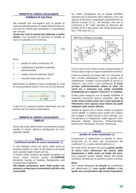
16 109 133 152 169 183 195 207 217 227 236 245 25 0,94 0,93 0,91 0,89 0,87 0,86 0,84 0,82 0,81 0,80 0,79 0,7 133 164 189 210 229 245 260 274 287 299 310 32 0,93 0,94 0,93 0,92 0,91 0,90 0,89 0,87 0,86 0,85 0,84 0,8 152 189 219 244 266 286 305 321 337 352 365 37 0,91 0,93 ESEMPIO 0,94 PRIMA 0,94 TABELLA 0,93 PROPOSTA 0,92 0,91 PER 0,90 0,89 DETERMINARE 169 210 I DIAMETRI 244 273 EQUIVALENTI 299 DEI 322 CONDOTTI 343 RETTANGOLARI 363 381 0,89 0,92 0,94 0,94 0,94 0,93 0,93 0,92 0,91 0,88 398 0,90 0,87 414 0,90 0,8 42 0,8 183 229 266 299 328 354 378 400 420 439 457 47 0,87 0,91 0,93 0,94 0,94 0,94 0,93 0,93 0,92 0,92 0,91 0,9 195 245 286 322 354 383 409 433 455 477 496 51 b 0,86 0,90 207 Base sezione 260 0,84 rettangolare 0,89 0,92 305 0,91 0,93 343 0,93 0,94 378 0,93 0,94 409 0,94 0,94 437 650 0,94 0,93 0,93 0,93 464 Altezza 488 sezione 511 0,94 rettangolare 0,94 0,93 0,92 533 0,93 0,9 55 0,9 217 274 321 363 400 433 464 492 518 543 567 58 0,82 0,87 0,90 0,92 0,93 0,93 0,94 0,94 0,94 0,94 0,93 0,9 Canali 227 rettangolari: 287 <strong>di</strong>ametri 337 equivalenti 381 per 420 la determinazione 455 488 delle <strong>per<strong>di</strong>te</strong> 518 <strong>di</strong> <strong>carico</strong> 547 continue 573 598 62 0,81 0,86 0,89 0,91 0,92 0,93 0,94 0,94 0,94 0,94 0,94 0,9 a, b = <strong>di</strong>mensioni rettangolo/quabrato, mm 236 299 352 Øe = <strong>di</strong>ametro equivalente, mm 398 439 477 511 f = fattore correttivo velocità 543 573 601 628 65 b a 100 0,80 150 0,85 200 250 0,88 300 350 0,90 400 450 0,92 500 550 0,93 600 0,93 650 700 0,94 750 800 0,94 a b 0,94 0,94 0,9 100 Øe 109 245 f 0,94 133 310 0,93 152 169 0,91 365 0,89 183 195 0,87414 0,86 207 217 0,84 457 0,82 227 236 0,81 496 0,80 245 533 0,79 253 261 0,77 567 0,76 268 275 0,75 598 0,74 Øe f 628 100 656 68 150 200 250 300 350 400 450 500 550 Øe 133 0,79 f 0,93 Øe 152 253 f 0,91 0,77 Øe 169 f 0,89 261 Øe 183 f 0,87 0,76 Øe 195 f 0,86 268 Øe 207 f 0,84 0,75 Øe 217 275 f 0,82 Øe 227 0,74 f 0,81 Øe 236 282 f 0,80 164 0,84 0,94 189 321 0,93 0,83 210 0,92 331 229 0,91 0,82 245 0,90 341 260 0,89 0,81 274 350 0,87 287 0,80 0,86 299 359 0,85 189 210 0,93 0,87 0,92 219 244 378 0,94 0,94 244 0,86 273 0,94 0,94 266 391 299 0,93 0,94 286 0,86 322 0,92 0,93 305 402 343 0,91 0,93 0,85 321 363 0,90 414 0,92 337 381 0,89 0,84 0,91 352 398 0,88 424 0,90 229 245 0,910,90 0,90 266 286 429 0,93 0,92 299 0,89322 0,94 0,93 328 443 354 0,94 0,94 354 0,88383 0,94 0,94 378 457 409 0,93 0,94 0,87 400 433 0,93470 0,93 420 455 0,920,87 0,93 439 477 0,92482 0,93 260 274 0,89 0,910,87 305 321 474 0,91 0,90 343 0,90363 0,93 0,92 378 490 400 0,93 0,93 409 0,90433 0,94 0,93 437 506 464 0,94 0,94 0,89 464 492 0,94 520 0,94 488 518 0,94 0,890,94 511 543 0,93 534 0,94 287 299 0,86 0,92 0,85 337 352 515 0,89 0,88 0,92 381 398 0,91 0,90 420 533 439 0,92 0,92 0,91 455 477 0,93 0,93 488 550 511 0,94 0,93 0,91 518 543 0,94 567 0,94 547 573 0,94 0,90 0,94 573 601 0,94 582 0,94 310 0,93 0,84 365 553 0,87 0,92 414 0,90 573 457 0,91 0,92 496 0,92 592 533 0,93 0,92 567 609 0,93 598 0,91 0,94 628 626 0,94 321 331 0,83 0,93 0,82 378 391 589 0,86 0,86 429 0,93 443 0,89 0,88 474 610 490 0,90 0,90 515 0,93 533 0,92 0,91 553 630 573 0,92 0,92 589 610 0,93 649 0,93 622 644 0,93 0,92 0,93 653 677 0,94 668 0,94 341 350 0,810,94 0,80 402 414 622 0,85 0,84 457 0,93 470 0,87 0,87 506 644 520 0,89 0,89 550 0,93 567 0,91 0,90 592 666 609 0,92 0,91 0,93 630 649 0,92 687 0,92 666 687 0,93 0,93 700 722 0,93 706 0,93 Øe f Øe f Øe f Øe f Øe f Øe f Øe f Øe f Øe f 0,94 150 653 200 0,94 250 677 300 0,94 350 700 400 0,93 450 722 500 0,93 743 550 0,94 683 0,94 708 0,94 732 0,94 755 0,93 778 0,9 71 0,9 73 0,9 76 0,9 78 0,9 81 600 Øe 245 0,74 f 0,79 310 0,79 0,84 365 414 0,87 0,83 0,90 457 496 0,910,86 0,92 533 567 0,93 0,880,93 598 628 0,94 0,89 0,94 656 0,91 0,94 683 708 0,94 0,92 0,94 732 755 0,940,92 0,93 Øe f 0,93 600 0,93 0,9 650 700 750 800 850 900 950 1000 1100 Øe 253 289 f 0,77 Øe 261 0,73 f 0,76 295 Øe 268 f 0,75 0,72 Øe 275 f 0,74 301 Øe 282 f 0,74 0,71 Øe 289 f 0,73 313 Øe 295 0,70 f 0,72 Øe 301 324 f 0,71 Øe 313 0,69 f 0,70 321 367 0,83 331 0,79 0,82 376 341 0,81 0,78 350 0,80 384 359 0,79 0,77 367 0,79 399 376 0,76 0,78 384 413 0,77 399 0,74 0,76 378 429 0,86 435 0,89 391 443 0,82 0,86 0,88 402 445 457 0,85 0,87 414 0,82 470 0,84 0,87 424 454 482 0,83 0,86 435 0,81 494 0,82 0,85 473 445 506 0,82 0,80 0,85 454 517 0,81 490 0,84 473 538 0,80 0,79 0,83 474 515 0,90494 0,92 490 533 0,85 0,90 0,91 506 506 550 0,89 0,91 520 0,85567 0,89 0,90 534 517 582 0,88 0,89 548 0,84597 0,87 0,89 538 561 612 0,870,83 0,88 574 626 0,86558 0,88 598 652 0,850,82 0,87 553 589 0,92 548 0,93 573 610 0,87 0,92 0,93 592 561 630 0,92 0,92 609 0,87649 0,91 0,92 626 574 668 0,91 0,92 643 0,86686 0,90 0,91 598 659 703 0,90 0,850,91 674 719 0,89 620 0,90 703 751 0,88 0,840,89 622 653 0,93 597 0,94 644 677 0,89 0,93 0,94 666 612 700 0,93 0,93 0,88 687 722 0,93 0,93 706 626 743 0,92 0,93 0,88 726 763 0,92 0,92 652 744 783 0,92 0,87 0,92 762 802 0,91 677 0,92 795 838 0,90 0,86 0,91 683 643 0,94 708 0,90 0,94 659 732 0,94 0,90 755 0,93 674 778 0,93 0,89 799 0,93 703 820 0,88 0,93 840 731 0,92 878 0,87 0,92 711 737 0,94 686 0,94 737 765 0,91 0,94 0,94 763 703 792 0,94 0,94 787 0,91 818 0,94 0,94 811 719 842 0,93 0,94 833 0,90 866 0,93 0,93 751 855 889 0,93 0,89 0,93 876 911 0,93 780 0,93 916 953 0,92 0,89 0,93 763 787 0,94 726 0,94 792 818 0,92 0,94 0,94 820 744 847 0,94 0,94 847 0,92 875 0,94 0,94 872 762 901 0,94 0,94 897 0,91 927 0,94 0,94 795 921 952 0,940,90 0,94 944 976 0,93 827 0,94 988 1.022 0,930,90 0,93 Øe f Øe f Øe f Øe f Øe f Øe f Øe f Øe f Øe f 763 650 0,92 700 783 750 0,92 800 802 850 0,92 900 838 950 0,91 1000 872 0,90 1100 799 0,93 820 0,93 840 0,92 878 0,92 914 0,91 83 0,9 85 0,9 87 0,9 91 0,9 95 0,9 1200 Øe 324 334 f 0,69 413 426 0,74 490 558 0,79 506 0,82 620 677 0,84577 0,86 731 780 0,87 642 0,89 827 872 0,90 701 0,90 914 757 0,91 954 993 0,92 808 0,92 1.030 1.066 0,93 857 0,93 Øe f 904 1200 948 99 1300 1400 1500 1600 1700 1800 1900 2000 Øe 334 0,67 f 0,67 Øe 344 344 f 0,66 0,66 Øe 353 f 0,65 353 Øe 362 f 0,64 0,65 Øe 371 f 0,64 362 Øe 379 f 0,63 0,64 Øe 387 371 f 0,62 Øe 395 0,64 f 0,61 426 0,73 0,73 439 0,72 0,72 452 0,71 452 463 0,70 0,71 475 0,69 463 485 0,69 0,70 496 475 0,68 506 0,69 0,67 506 577 0,77 0,77 0,80 522 595 522 0,76 0,79 536 0,76 612 0,75 0,79 551 536 629 0,74 0,78 564 0,75 644 0,74 0,77 577 551 660 0,73 0,76 0,74 590 674 0,72 564 0,75 602 688 0,71 0,74 642 701 0,830,80 0,85 662 724 595 0,82 0,84 681 0,79745 0,81 0,83 700 612 766 0,80 0,82 718 0,79785 0,79 0,81 735 629 804 0,79 0,81 0,78 751 823 0,78644 0,80 767 840 0,77 0,77 0,79 757 808 0,86 0,830,88 781 835 662 0,86 0,87 805 0,82860 0,85 0,86 827 681 885 0,84 0,85 849 0,81908 0,83 0,85 869 700 930 0,82 0,84 0,80 889 952 0,82 718 0,83 908 973 0,8 0,790,83 857 904 0,89 0,85 0,90 886 934 724 0,88 0,89 0,84 913 963 0,87 0,88 939 745 991 0,87 0,88 0,83 964 1.018 0,86 0,87 988 766 1.043 0,85 0,86 0,82 1.012 1.068 0,85 785 0,86 1.034 1.092 0,84 0,81 0,85 948 990 1.031 0,86 0,90 0,91 0,88 0,92 980 1.024 1.066 781 835 0,90 0,91 0,91 0,86 1.011 1.057 0,87 1.100 0,89 0,90 0,91 1.041 805 1.088 860 1.133 0,89 0,89 0,90 0,85 1.069 1.118 0,86 1.164 0,88 0,89 0,89 1.096 827 1.146 885 1.195 0,87 0,88 0,89 0,84 0,85 1.122 1.174 1.224 849 0,87 0,88 908 0,88 1.147 1.200 1.252 0,83 0,86 0,87 0,85 0,88 1.069 1.107 0,920,89 0,92 1.107 1.146 886 0,92 0,92 1.143 0,88 1.183 0,91 0,92 1.177 913 1.219 0,91 0,91 1.209 0,87 1.253 0,90 0,91 1.241 939 1.286 0,90 0,90 0,87 1.271 1.318 0,89 964 0,90 1.301 1.348 0,890,86 0,89 Øe f 0,90 1300 Øe 934 1400 f Øe 0,89 f 1500 Øe 963 f 1600 Øe 0,88 1700 f 991 Øe f 1800 0,88 Øe 1900 f 1.018 Øe f 2000 0,87 0,90 980 0,90 1.011 0,89 1.041 0,89 1.069 0,88 0,9 1.02 0,9 1.05 0,9 1.08 0,8 1.11 0,8 2200 Øe 410 379 f 0,60 525 485 0,66 625 715 0,70 577 0,73 797 874 0,76660 0,78 945 1.013 0,80 735 0,81 1.076 1.137 0,83 804 0,84 1.195 1.251 869 0,85 0,86 1.305 930 0,87 1.356 1.406 0,88 988 0,88 Øe 2200 f 1.043 1.096 1.14 0,63 0,69 0,73 0,76 0,79 0,81 0,82 0,84 0,85 0,86 0,87 0,8 80-1a 387 496 590 674 751 CALEFFI 823 889 952 1.012 1.068 80-1a 1.122 1.17 0,62 0,68 0,72 0,75 0,78 0,80 0,82 0,83 0,85 0,86 0,87 0,8 395 506 602 688 767 840 908 973 1.034 1.092 1.147 1.20 0,61 0,67 0,71 0,74 0,77 0,79 0,8 0,83 0,84 0,85 0,86 0,8 410 525 Diametro 625 equivalente 715 797 874 Numero 945 <strong>di</strong> 1.013 riferimento 1.076 tabella 1.137 80-1a 1.195 1.25 0,60 0,66 Fattore 0,70 correttivo 0,73 velocità 0,76 0,78 0,80 0,81 0,83 0,84 0,85 0,8 pag. 16
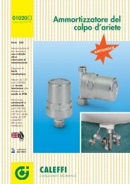
PERDITE DI CARICO LOCALIZZATE FORMULE DI CALCOLO Nei condotti che convogliano aria, le <strong>per<strong>di</strong>te</strong> <strong>di</strong> <strong>carico</strong> localizzate possono essere determinate con uno <strong>dei</strong> tre meto<strong>di</strong> già considerati in precedenza per l’acqua. Anche per l’aria il metodo più utilizzato è quello <strong>di</strong>retto, che consente <strong>di</strong> calcolare le <strong>per<strong>di</strong>te</strong> <strong>di</strong> <strong>carico</strong> localizzate con la formula: v 2 z = ξ · ρ · (12) 2 dove: z = per<strong>di</strong>ta <strong>di</strong> <strong>carico</strong> localizzata, Pa ξ = coefficiente <strong>di</strong> per<strong>di</strong>ta localizzata, a<strong>di</strong>mensionale ρ = massa volumica dell’aria, Kg/m 3 v = velocità me<strong>di</strong>a dell’aria, m/s Esprimendo le <strong>per<strong>di</strong>te</strong> <strong>di</strong> <strong>carico</strong> localizzate in unità <strong>di</strong> misura pratiche (cioè in mm c.a.) la (12) <strong>di</strong>venta: v 2 z = ξ · ρ · (13) 2 · 9,81 I valori <strong>di</strong> [ ξ ] possono essere determinati sia con formule sia con prove <strong>di</strong> laboratorio. PERDITE DI CARICO LOCALIZZATE TABELLE Anche per poter determinare manualmente queste <strong>per<strong>di</strong>te</strong> <strong>di</strong> <strong>carico</strong>, abbiamo pre<strong>di</strong>sposto ex novo apposite tabelle. Tabelle coefficienti <strong>per<strong>di</strong>te</strong> <strong>di</strong> <strong>carico</strong> localizzate [ ξ ] In vero abbiamo avuto non pochi dubbi prima <strong>di</strong> proporre tabelle coi valori <strong>di</strong> [ ξ ] relativi ai principali pezzi speciali degli <strong>impianti</strong> ad aria. In merito, infatti, esistono già tabelle complete e <strong>di</strong> sicuro valore tecnico: quelle dell’ASHRAE (American Society of Heating, Refrigeratine and Con<strong>di</strong>tioning Engineers). Tali tabelle presentano, però, limiti pratici che possono comportare inconvenienti tutt’altro che trascurabili. Va, infatti, considerato che le tabelle ASHRAE riportano più <strong>di</strong> duecento pezzi speciali e che, per ognuno <strong>di</strong> tali pezzi, propongono generalmente un elevato numero <strong>di</strong> [ ξ ] . Ad esempio, solo per la confluenza a 45° sotto riportata (in relazione alle portate d’aria e alle sezioni <strong>dei</strong> canali) propongono ben 1.458 valori <strong>di</strong> [ ξ ]. È ovvio che un tal numero <strong>di</strong> dati comporta tempi <strong>di</strong> ricerca assai lunghi ed espone facilmente ad errori. Inoltre la presenza <strong>di</strong> troppi dati non consente <strong>di</strong> farsi un’idea abbastanza chiara <strong>di</strong> quanto può me<strong>di</strong>amente “costare” (come <strong>per<strong>di</strong>te</strong> <strong>di</strong> <strong>carico</strong>) un imbocco, una curva o una confluenza. E avere un’idea sufficientemente chiara <strong>di</strong> tutto ciò serve sia a maturare una valida sensibilità progettuale sia a sapersi “muovere” in cantiere. D’altra parte inseguire con le tabelle ASHRAE la massima precisione teorica possibile, non ha molto senso pratico dato che i pezzi speciali <strong>di</strong> riferimento sono spesso assai <strong>di</strong>versi da quelli realizzati nelle nostre officine. Queste le ragioni che ci hanno indotto a proporre nuove tabelle. In pratica sono quelle che usiamo per svolgere il nostro lavoro e sono derivate, con comparazioni e integrazioni, dalle seguenti fonti: Manuale Marelli Aeraulica, Rietschell-Rais, Kraft-Kurth, Missenard, Porcher, Perrenoud. Tabelle <strong>per<strong>di</strong>te</strong> <strong>di</strong> <strong>carico</strong> localizzate [z ] Consentono <strong>di</strong> determinare le <strong>per<strong>di</strong>te</strong> <strong>di</strong> <strong>carico</strong> localizzate [z] in base alla conoscenza <strong>dei</strong> coefficienti [ ξ ] e delle velocità dell’aria [ v ]. Per tener conto del fatto che anche queste <strong>per<strong>di</strong>te</strong> <strong>di</strong> <strong>carico</strong> sono influenzate dal variare della temperatura e della quota sul livello del mare, sono proposte quattro tabelle relative alle stesse con<strong>di</strong>zioni previste per le <strong>per<strong>di</strong>te</strong> <strong>di</strong> <strong>carico</strong> continue. Nota: Con i canali rettangolari le velocità da considerarsi per determinare [ z ] sono quelle effettive e non quelle che corrispondono alle sezioni equivalenti. 17
- Page 1 and 2: giugno 2005 SPEDIZIONE IN ABBONAMEN
- Page 3 and 4: LE PERDITE DI CARICO NEGLI IMPIANTI
- Page 5 and 6: Il regime di moto di un fluido è i
- Page 7 and 8: TABELLE E DIAGRAMMI PERDITE DI CARI
- Page 9 and 10: Portate, l/h 3,5 m/s Velocità Perd
- Page 11 and 12: v 0,10 0,12 0,14 0,16 0,18 0,20 0,2
- Page 13 and 14: Determinazione del fattore di attri
- Page 15: Perdite di carico continue, mm c.a.
- Page 19 and 20: Perdite di carico localizzate per
- Page 21 and 22: Standard per boiler Configurazione
- Page 23 and 24: DIMENSIONAMENTO Scelto il sottogrup
- Page 25 and 26: DIMENSIONAMENTO Come nel caso prece
- Page 27 and 28: ESEMPIO DI STAMPA DIMENSIONAMENTO M
- Page 29 and 30: ESEMPIO DI STAMPA DIMENSIONAMENTO M
- Page 31 and 32: Su Idraulica, e siamo ormai alla pr
- Page 33 and 34: Miscelatori termostatici per impian
- Page 35 and 36: Valvole di sicurezza temperatura e