
You also want an ePaper? Increase the reach of your titles
YUMPU automatically turns print PDFs into web optimized ePapers that Google loves.
1
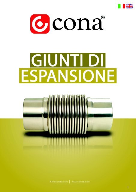
GIUNTI DI ESPANSIONE /EXPANSION JOINTS<br />
GIUNTI DI ESPANSIONE<br />
Una delle leggi principali della fisica è che i materiali si espandono e si comprimono a<br />
seconda del variare della temperatura e della pressione. I giunti <strong>di</strong> espansione sono gli<br />
elementi che assorbono <strong>di</strong>latazioni, compressioni e vibrazioni e che permettono ai sistemi<br />
industriali <strong>di</strong> lavorare senza sosta e in modo efficiente. I giunti <strong>di</strong> espansione in acciaio<br />
sono utilizzati principalmente in apparecchiature, macchine, sistemi <strong>di</strong> condutture e<br />
in meccanismi <strong>di</strong> uscita a pompa dove lo spazio <strong>di</strong> installazione e manutenzione è<br />
limitato. Essi sono scelti per: compensare i movimenti in <strong>di</strong>rezioni specifiche; compensare<br />
le espansioni e le compressioni; ridurre lo stress; evitare rumori e oscillazione nella<br />
trasmissione; compensare gli assestamenti del terreno e delle fondamenta; eliminare le<br />
imprecisioni dell'installazione.<br />
I giunti <strong>di</strong> espansione possono essere classificati in tre gruppi a seconda dei tipi <strong>di</strong><br />
movimento che devono essere assorbiti: 1) <strong>Giunti</strong> <strong>di</strong> espansione assiale; 2) <strong>Giunti</strong> <strong>di</strong><br />
espansione laterale; 3) <strong>Giunti</strong> <strong>di</strong> espansione angolare. In particolare, CONA fornisce i<br />
seguenti prodotti: <strong>Giunti</strong> <strong>di</strong> espansione assiale, <strong>Giunti</strong> <strong>di</strong> espansione assiale X-Pressed,<br />
<strong>Giunti</strong> <strong>di</strong> espansione con limitatore <strong>di</strong> corsa, <strong>Giunti</strong> <strong>di</strong> espansione cardanici doppi, <strong>Giunti</strong><br />
antivibranti, <strong>Giunti</strong> <strong>di</strong> espansione per teleriscaldamento, <strong>Giunti</strong> con soffietto trecciato,<br />
<strong>Giunti</strong> <strong>di</strong> espansione tubolari, <strong>Giunti</strong> <strong>di</strong> espansione in gomma.<br />
EXPANSION JOINTS<br />
One of the basic rules of physics is that materials expand and compress because<br />
of temperature changes. Expansion joints are the elements that absorb all those<br />
expansions, compressions and also vibrations and that let the industrial systems work<br />
continuously and efficiently. Steel expansion joints are mainly used in appliances,<br />
machines, piping systems, pump outlet mechanisms where the installation and<br />
maintenance space is limited. They are preferred to: compensate the movement in<br />
specific <strong>di</strong>rections; compensate the expansion and compression; reduce stress; prevent<br />
noise and oscillation transmission; compensate for ground and foundation settlement;<br />
eliminate the installation inaccuracies. Expansion joints can be classified into three<br />
groups accor<strong>di</strong>ng to the types of movement that must be absorbed: 1)Axial expansion<br />
joints 2)Lateral expansion joints 3) Angular expansion joints. In particular CONA offers<br />
the following items: Axial expansion joints, X-Pressed axial expansion joints, Universal tied<br />
<strong>di</strong>latation expansion joints (lateral), Double gimbal type expansion joints (3D), Vibration<br />
absorbers, District heating expansion joints, Braided loop joints, Pipe expansion joints,<br />
Rubber expansion joints.<br />
4
SIMBOLI PER LE CARATTERISTICHE E PER UNA RAPIDA SCELTA DEL PRODOTTO/ SYMBOLS FOR<br />
PRODUCT FEATURES AND QUICK SELECTION<br />
Giunto <strong>di</strong> <strong>Espansione</strong><br />
Assiale/ Axial<br />
Expansion Joint<br />
Giunto <strong>di</strong> <strong>Espansione</strong><br />
Laterale / Lateral<br />
Expansion Joint<br />
Giunto <strong>di</strong> <strong>Espansione</strong><br />
Angolare / Angular<br />
Expansion Joint<br />
Movimento 3D /<br />
3D Movement<br />
Connessione<br />
Filettata / Threaded<br />
Connection<br />
Pressione Massima<br />
del Prodotto/ Max.<br />
Product Pressure<br />
Standard Flangia /<br />
Flange Standard<br />
Standard Flangia /<br />
Flange Standard<br />
Temperatura<br />
Massima del<br />
Prodotto / Max.<br />
Product Temperature<br />
A Prova <strong>di</strong> Fiamma /<br />
Flame-proof<br />
Giunto <strong>di</strong> <strong>Espansione</strong><br />
Antisismico / Seismic<br />
Expansion Joint<br />
Adatto Per Flui<strong>di</strong><br />
Gassosi / Suitable<br />
for Gaseous Me<strong>di</strong>a<br />
Resistente all’Acqua<br />
Calda / Resistant to<br />
Hot Water<br />
Adatto per<br />
l’Assorbimento del<br />
Rumore/ Suitable for<br />
Noise Absorption<br />
Adatto per<br />
l’Assorbimento<br />
delle Vibrazioni/<br />
Suitable for Vibration<br />
Absorption<br />
Adatto Per Oli<br />
Combustibili /<br />
Suitable For Oils<br />
Adatto per Acqua<br />
Potabile/ Suitable<br />
for Drinking Water<br />
Adatto per acqua <strong>di</strong><br />
mare / Suitable for<br />
Seawater<br />
5
GIUNTI DI ESPANSIONE /EXPANSION JOINTS<br />
GIUNTI DI ESPANSIONE ASSIALE / AXIAL EXPANSION JOINTS<br />
I giunti <strong>di</strong> espansione assiale hanno<br />
il compito <strong>di</strong> assorbire i movimenti<br />
assiali. Inoltre:<br />
• Essi non mo<strong>di</strong>fi cano la <strong>di</strong>rezione del fl usso<br />
• Non necessitano no <strong>di</strong> spazio aggiuntivo per il montaggio<br />
• Interrompendo la tubatura, aiutano a sopportare lo stress laterale<br />
le<br />
Assorbimento del Movimento<br />
Axial expansion joints aim at absorbing axial expansions. Moreover:<br />
• They do not change the <strong>di</strong>rection of the fl ow<br />
• Ad<strong>di</strong>tional assemblage <strong>di</strong>stance is not necessary<br />
• Divi<strong>di</strong>ng the pipeline, they help to prevent the stress of lateral<br />
forces<br />
Movement Absorption<br />
Consentono il movimento assiale e tutti i più piccoli movimenti<br />
multi<strong>di</strong>rezionali delle tubazioni ad esse connessi. Inoltre, i giunti <strong>di</strong><br />
espansione con due soffi etti sono utilizzati per assorbire movimenti<br />
più ampi.<br />
Vantaggi dei <strong>Giunti</strong> <strong>di</strong> <strong>Espansione</strong> Assiale<br />
• Facile assorbimento dei movimenti <strong>di</strong> espansione<br />
• Nessun cambiamento nella <strong>di</strong>rezione del fl usso<br />
• Area <strong>di</strong> applicazione ridotta<br />
• Possibile assorbimento <strong>di</strong> espansione laterale ed angolare tramite<br />
soffi etti aggiuntivi<br />
• Preparazione <strong>di</strong> un’area in cui la pressione non risulta troppo alta,<br />
come nelle applicazioni <strong>di</strong> pompe e compressori<br />
• Bassi costi <strong>di</strong> intervento<br />
Axial shift and slight all-around movements of the expansion joint<br />
are possible. Axial expansion joints with two bellows are used to absorb<br />
larger movements.<br />
Advantages of Axial Expansion Joints<br />
• Easy absorption of expansion movements<br />
• No <strong>di</strong>rection changes of the fl ow<br />
• Minimum application area<br />
• Possible lateral and angular expansion absorption by ad<strong>di</strong>tional<br />
bellows<br />
• They provide a non-stressed area where the pressure is not too<br />
high such as pump and compressor applications<br />
Simulazione operativa del giunto <strong>di</strong> espansione assiale /<br />
Working simulation of axial expansion joint<br />
Movimenti del giunto <strong>di</strong> espansione assiale /<br />
Movement of axial expansion joint<br />
6<br />
I prodotti CONA sono soggetti ad alterazioni tecniche derivanti dal processo <strong>di</strong> produzione.
Valore <strong>di</strong> espansione assiale -10/+20 mm, senza manicotto interno / Axial expansion value -10/+20 mm, without inner sleeve<br />
Flangia / Flange (DIN EN 1092/1) PN 16<br />
DN ØD Øk Ø d4 f b Ød x n Ø<strong>di</strong> Ødo<br />
[mm] [mm] [mm] [mm] [mm]<br />
Materiale del soffietto: Acciaio inox AISI321<br />
(opzionale 304, 316L, 316TI, 309)<br />
Diametro nominale: DN15 (1/2”) - DN3800<br />
(152”)<br />
Pressione <strong>di</strong> esercizio: PN 2,5/6/16/25/40/64<br />
Temperatura <strong>di</strong> esercizio: -80°C/+600°C<br />
Tipologia <strong>di</strong> connessione: Flangia fi ssa,<br />
fl angia mobile e a saldare<br />
Materiale delle connessioni: Acciaio al<br />
carbonio St.37.2 (il materiale può essere<br />
personalizzato su richiesta)<br />
Opzionale: Manicotto interno in acciaio<br />
inox AISI321 (a scelta 304, 316L, 316TI, 309)<br />
[mm] x<br />
nr. fori /<br />
per holes<br />
number<br />
Soffietto / Bellow<br />
Area<br />
effettiva<br />
del soffietto<br />
/<br />
Effective<br />
bellow<br />
area<br />
Valore <strong>di</strong><br />
elasticità<br />
assiale<br />
/ Axial<br />
elasticity<br />
value<br />
L<br />
Flangia fissa /<br />
Fixed Flange<br />
MKSF-30<br />
Co<strong>di</strong>ce /<br />
Code<br />
[mm] [mm] [cm 2 ] [N/mm] [mm] [mm]<br />
L<br />
Flangia mobile /<br />
Floating Flange<br />
MKDF-30<br />
Co<strong>di</strong>ce /<br />
Code<br />
DN25 115 85 68 2 16 Ø 14 x 4 38 48,2 14,58 82,1 120 702041101002 110 702031101002<br />
DN32 140 100 78 2 18 Ø 18 x 4 42,4 55 18,62 49,7 125 702041101004 115 702031101004<br />
DN40 150 110 88 3 18 Ø 18 x 4 48,3 61 23,44 60,8 130 702041101006 120 702031101006<br />
DN50 165 125 102 3 20 Ø 18 x 4 60,3 76 36,46 104,5 120 702041101008 110 702031101008<br />
DN65 185 145 122 3 20 Ø 18 x 4 76,1 95 57,45 87,8 120 702041101010 110 702031101010<br />
DN80 200 160 138 3 20 Ø 18 x 8 88,9 111 78,42 178,9 120 702041101012 110 702031101012<br />
DN100 220 180 158 3 22 Ø 18 x 8 114,3 140 137,09 252,2 130 702041101014 115 702031101014<br />
DN125 250 210 188 3 22 Ø 18 x 8 139,7 164 181,01 320 135 702041101016 130 702031101016<br />
DN150 285 240 212 3 24 Ø 23 x 8 168,3 200 266,20 196,4 160 702041101018 145 702031101018<br />
DN200 340 295 268 3 26 Ø 23 x 12 219,1 250 431,86 694,2 160 702041101020 140 702031101020<br />
DN250 405 355 320 3 29 Ø 27 x 12 273 323 697,11 590 170 702041101022 150 702031101022<br />
DN300 460 410 378 4 32 Ø 27 x 12 323,9 380 972,37 496,8 170 702041101024 150 702031101024<br />
Valore <strong>di</strong> espansione assiale -10/+20 mm, con manicotto interno / Axial expansion value -10/+20 mm, with inner sleeve<br />
MKSF-30L<br />
MKDF-30L<br />
DN25 115 85 68 2 16 Ø 14 x 4 38 48,2 14,58 82.1 120 702041102002 110 702031102002<br />
DN32 140 100 78 2 18 Ø 18 x 4 42,4 55 18,62 49,7 125 702041102004 115 702031102004<br />
DN40 150 110 88 3 18 Ø 18 x 4 48,3 61 23,44 60,8 130 702041102006 120 702031102006<br />
DN50 165 125 102 3 20 Ø 18 x 4 60,3 76 36,46 104,5 120 702041102008 110 702031102008<br />
DN65 185 145 122 3 20 Ø 18 x 4 76,1 95 57,45 87,8 120 702041102010 110 702031102010<br />
DN80 200 160 138 3 20 Ø 18 x 8 88,9 111 78,42 178,9 120 702041102012 110 702031102012<br />
DN100 220 180 158 3 22 Ø 18 x 8 114,3 140 137,09 252,2 130 702041102014 115 702031102014<br />
DN125 250 210 188 3 22 Ø 18 x 8 139,7 164 181,01 320 135 702041102016 130 702031102016<br />
DN150 285 240 212 3 24 Ø 23 x 8 168,3 200 266,20 196,4 160 702041102018 145 702031102018<br />
DN200 340 295 268 3 26 Ø 23 x 12 219,1 250 431,86 694,2 160 702041102020 140 702031102020<br />
DN250 405 355 320 3 29 Ø 27 x 12 273 323 697,11 590 170 702041102022 150 702031102022<br />
DN300 460 410 378 4 32 Ø 27 x 12 323,9 380 972,37 496,8 170 702041102024 150 702031102024<br />
I prodotti CONA sono soggetti ad alterazioni tecniche derivanti dal processo <strong>di</strong> produzione.<br />
Bellow material: Stainless steel AISI321<br />
(Opt. 304, 316L, 316TI, 309)<br />
Nominal <strong>di</strong>ameter: DN15 (1/2”) - DN3800<br />
(152”)<br />
Operating pressure: PN 2,5/6/16/25/40/64<br />
Operating temperature: -80°C/+600°C<br />
Connection types: Fixed and fl oating<br />
fl ange and welded ends<br />
Connection material: Carbon steel<br />
St.37.2 as standard (the material can be<br />
customized on request)<br />
Optional: Inner sleeve in stainless steel<br />
AISI321 (Opt. 304, 316L, 316TI, 309)<br />
Altri <strong>di</strong>ametri del giunto e tipologie della<br />
flangia (ANSI, BS, UNI) sono <strong>di</strong>sponibili su<br />
richiesta/<br />
Other joint <strong>di</strong>ameters and flange types<br />
(ANSI, BS, UNI) are available on request<br />
7
GIUNTI DI ESPANSIONE /EXPANSION JOINTS<br />
Valore <strong>di</strong> espansione assiale -20/+40 mm, con manicotto interno / Axial expansion value -20/+40 mm, with inner sleeve<br />
Flangia / Flange (DIN EN 1092/1) PN 16<br />
DN ØD Øk Ø d4 f b Ød x n Ø<strong>di</strong> Ødo<br />
[mm] [mm] [mm] [mm] [mm]<br />
[mm] x<br />
nr. fori /<br />
per holes<br />
number<br />
Soffietto / Bellow<br />
Area<br />
effettiva<br />
del soffietto<br />
/<br />
Effective<br />
bellow<br />
area<br />
Valore <strong>di</strong><br />
elasticità<br />
assiale<br />
/ Axial<br />
elasticity<br />
value<br />
L<br />
Flangia fissa /<br />
Fixed Flange<br />
MKSF-60L<br />
Co<strong>di</strong>ce /<br />
Code<br />
[mm] [mm] [cm 2 ] [N/mm] [mm] [mm]<br />
Flangia mobile /<br />
Floating Flange<br />
L<br />
MKDF-60L<br />
Co<strong>di</strong>ce /<br />
Code<br />
DN50 165 125 102 3 20 Ø 18 x 4 60,3 76 36,46 55,7 200 702041202008 190 702031202008<br />
DN65 185 145 122 3 20 Ø 18 x 4 76,1 95 57,45 43,9 205 702041202010 195 702031202010<br />
DN80 200 160 138 3 20 Ø 18 x 8 88,9 111 78,42 89,4 200 702041202012 190 702031202012<br />
DN100 220 180 158 3 22 Ø 18 x 8 114,3 140 137,09 126,1 215 702041202014 200 702031202014<br />
DN125 250 210 188 3 22 Ø 18 x 8 139,7 164 181,01 160,0 225 702041202016 210 702031202016<br />
DN150 285 240 212 3 24 Ø 23 x 8 168,3 200 266,20 98,2 250 702041202018 245 702031202018<br />
DN200 340 295 268 3 26 Ø 23 x 12 219,1 250 431,86 347,1 265 702041202020 245 702031202020<br />
DN250 405 355 320 3 29 Ø 27 x 12 273 323 697,11 295 270 702041202022 250 702031202022<br />
DN300 460 410 378 4 32 Ø 27 x 12 323,9 380 972,37 248,4 270 702041202024 250 702031202024<br />
Nome / Name Valore <strong>di</strong> espansione /<br />
Expansion value<br />
DN<br />
ØDi<br />
ØDo<br />
Soffietto / Bellow<br />
Area effettiva del<br />
soffietto / Effective<br />
bellow area<br />
Valore <strong>di</strong> elasticità<br />
assiale / Axial<br />
elasticity value<br />
S<br />
Caratteristiche / Features<br />
MKKB-30 -10/+20 mm Connessioni a saldare, senza manicotto interno / Butt-wel<strong>di</strong>ng ends, without inner sleeve<br />
MKKB-30L -10/+20 mm Connessione a saldare, con manicotto interno / Butt-wel<strong>di</strong>ng ends, with inner sleeve<br />
MKKB-60L -20/+40 mm Connessione a saldare, con manicotto interno / Butt-wel<strong>di</strong>ng ends, with inner sleeve<br />
L<br />
MKKB-30 MKKB-30L MKKB-60L<br />
Co<strong>di</strong>ce /<br />
Code<br />
L<br />
Co<strong>di</strong>ce /<br />
Code<br />
[mm] [mm] [cm 2 ] [N/mm] [mm] [mm] [mm] [mm]<br />
DN25 38 48,8 14,58 82,1 2,6 210 702051101006 210 702051102006<br />
DN32 42,4 55,6 18,62 49,7 2,6 215 702051101008 215 702051102008<br />
DN40 48,3 61,5 23,44 60,8 2,6 220 702051101010 220 702051102010<br />
L<br />
Co<strong>di</strong>ce /<br />
Code<br />
DN50 60,3 76,9 36,46 104,5 2,9 210 702051101012 210 702051102012 290 702051202012<br />
DN65 76,1 95,9 57,45 87,8 2,9 210 702051101014 210 702051102014 285 702051202014<br />
DN80 88,9 112,1 78,42 178,9 3,2 215 702051101016 215 702051102016 300 702051202016<br />
DN100 114,3 140,9 137,09 252,2 3,6 215 702051101018 215 702051102018 300 702051202018<br />
DN125 139,7 165,7 181,01 320 4 220 702051101020 220 702051102020 310 702051202020<br />
DN150 168,3 201,1 266,20 196,4 4,5 245 702051101022 245 702051102022 345 702051202022<br />
DN200 219,1 252,3 431,86 694,2 6,3 235 702051101024 235 702051102024 340 702051202024<br />
DN250 273 325,8 697,11 590 6,3 240 702051101026 240 702051102026 340 702051202026<br />
DN300 323,9 382,9 972,37 496,8 7,1 250 702051101028 250 702051102028 340 702051202028<br />
8<br />
I prodotti CONA sono soggetti ad alterazioni tecniche derivanti dal processo <strong>di</strong> produzione.
GIUNTI DI ESPANSIONE ASSIALE / AXIAL EXPANSION JOINTS► GIUNTO ANTIVIBRANTE FLAN-<br />
GIATO PER GAS A SOFFIETTO METALLICO UNICIG 8041-8042 / METAL BELLOW VIBRATION<br />
JOINT WITH FLANGED ENDS FOR GAS UNICIG 8041-8042<br />
Materiale del soffietto: Acciaio inox AISI321<br />
Pressione <strong>di</strong> esercizio: PN 2,5<br />
Tipologia <strong>di</strong> connessione: Flangia mobile<br />
Materiale delle connessioni: Acciaio al<br />
carbonio St.37.2 zincato<br />
Bellow material: Stainless steel AISI321<br />
Operating pressure: PN 2,5<br />
Connection types: Floating fl ange<br />
Connection material: Galvanized carbon<br />
steel St.37.2<br />
DN<br />
Flangia / Flange<br />
ØD Øk b Ød x n ØDi ØDo<br />
[mm] [mm] [mm]<br />
[mm] x nr.<br />
fori<br />
Soffietto / Bellow<br />
Spessore<br />
parete<br />
/ Wall<br />
thickness<br />
Numero<br />
<strong>di</strong> spire /<br />
Number of<br />
convolutions<br />
L<br />
Movimento / Movement<br />
Assiale<br />
/ Axial<br />
Laterale<br />
/ Lateral<br />
Angolare<br />
/ Angular<br />
[N/mm] [mm] [mm] [mm] [mm] [mm] [°]<br />
Co<strong>di</strong>ce /<br />
Code<br />
DN40 165 110 14 Ø 18 x 4 48.3 61 0.30 20 135 ± 15 ± 12 20 702033101006<br />
DN50 165 125 14 Ø 18 x 4 60.3 76 0.40 18 155 ± 15 ± 12 20 702033101008<br />
DN65 185 145 14 Ø 18 x 4 76.1 95 0.40 18 155 ± 20 ± 13 19 702033101010<br />
DN80 200 160 16 Ø 18 x 8 88.9 111 0.40 14 165 ± 25 ± 15 19 702033101012<br />
DN100 220 180 16 Ø 18 x 8 114.3 140 0.40 15 175 ± 35 ± 17 18 702033101014<br />
DN125 250 210 18 Ø 18 x 8 139.7 165 0.40 15 195 ± 35 ± 15 15 702033101016<br />
DN150 285 240 18 Ø 23 x 8 168.3 200 0.50 13 200 ± 35 ± 15 15 702033101018<br />
DN200 340 295 20 Ø 23 x 12 219.1 251 0.50 14 220 ± 35 ± 13 12 702033101020<br />
DN250 405 355 22 Ø 27 x 12 273 305 0.60 11 225 ± 25 ± 8 9 702033101022<br />
I prodotti CONA sono soggetti ad alterazioni tecniche derivanti dal processo <strong>di</strong> produzione.<br />
9
GIUNTI DI ESPANSIONE /EXPANSION JOINTS<br />
GIUNTI DI ESPANSIONE ASSIALE / AXIAL EXPANSION JOINTS► X-PRESSED, GIUNTO DI<br />
ESPANSIONE PRESSURIZZATO ESTERNAMENTE/ EXTERNALLY PRESSURIZED EXPANSION JOINT<br />
L’assorbimento <strong>di</strong> elevati valori <strong>di</strong> espansione termica tramite giunti<br />
<strong>di</strong> espansione assiale è possibile solo aumentando il numero <strong>di</strong> ondulazioni<br />
del soffi etto, ma ciò aumenta anche la possibilità <strong>di</strong> torsione.<br />
L’applicazione <strong>di</strong> manicotti interni puo ridurre la torsione ma<br />
anche la capacità <strong>di</strong> movimento dei giunti <strong>di</strong> espansione. I<br />
giunti <strong>di</strong> espansione CONA a pressione esterna forniscono la soluzione<br />
migliore per casi come quelli sopraccitati.<br />
Assorbimento del Movimento<br />
I giunti <strong>di</strong> espansione X-pressed cambiano la <strong>di</strong>rezione del fl usso<br />
ed in<strong>di</strong>rizzano la pressione <strong>di</strong> quest’ultimo verso i soffi etti esterni. La<br />
resistenza dei soffi etti, pressurizzati esternamente, all’alta pressione<br />
e alle forze <strong>di</strong> torsione, aumenta. Questa struttura stabile rende possibile<br />
l’assorbimento in sicurezza dei movimenti piu ampi.<br />
Vantaggi dei <strong>Giunti</strong> <strong>di</strong> <strong>Espansione</strong> X-Pressed<br />
• Facile assorbimento <strong>di</strong> ampi movimenti <strong>di</strong> espansione<br />
ris-<br />
• Riduzione del numero <strong>di</strong> giunti <strong>di</strong> espansione assiale con<br />
parmio <strong>di</strong> tempo e costi<br />
• Area <strong>di</strong> applicazione ridotta<br />
• Prevenzione <strong>di</strong> imperfezioni assiali con relativo aumento della sicurezza<br />
del sistema<br />
Compensating larger amount of thermal expansions by axial expansion<br />
joints is only possible by increasing the number of corrugations<br />
of the bellow, but this increases the possibility of torsion. Applying<br />
inner sleeves may reduce the torsion but it also reduces the movement<br />
capacity of the expansion joints. CONA externally pressurized<br />
expansion joints provide the most suitable solution for such cases.<br />
Movement Absorption<br />
X-pressed expansion joints change the <strong>di</strong>rection of the fl ow and<br />
convey the pressure to the bellows externally. Resistance of externally<br />
pressurized bellows against high pressure and torsion forces increases.<br />
This fi rm structure makes compensating large movements<br />
possible safely.<br />
Advantages of X-Pressed Expansion Joints<br />
• Easy absorption of large expansion movements<br />
• Reducing the number of axial expansion joints saves time and cost<br />
• Minimum application area<br />
• Preventing axial inaccuracies increases the system safety<br />
• Using internal guide rings provides highly stable structure for connections<br />
• Utilizzo <strong>di</strong> anelli <strong>di</strong> guida interna, che assicurano una struttura altamente<br />
stabile per le connessioni<br />
10<br />
I prodotti CONA sono soggetti ad alterazioni tecniche derivanti dal processo <strong>di</strong> produzione.
Materiale del soffietto: Acciaio inox AISI321<br />
(opzionale 304, 316L, 316TI, 309)<br />
Diametro nominale: DN15 (1/2”) - DN3800<br />
(152”)<br />
Pressione <strong>di</strong> esercizio: PN 2,5/6/16/25/40/64<br />
Temperatura <strong>di</strong> esercizio: -80°C/+600°C<br />
Tipologia <strong>di</strong> connessione: Flangia fi ssa,<br />
fl angia mobile e a saldare<br />
Materiale delle connessioni: Acciaio al<br />
carbonio St.37.2 (il materiale può essere<br />
personalizzato su richiesta)<br />
Opzionale: Manicotto interno in acciaio<br />
inox AISI321 (a scelta. 304, 316L, 316TI, 309)<br />
Altri <strong>di</strong>ametri del giunto e tipologie della<br />
flangia (ANSI, BS, UNI) sono <strong>di</strong>sponibili su<br />
richiesta<br />
Bellow material: Stainless steel AISI321<br />
(Opt. 304, 316L, 316TI, 309)<br />
Nominal <strong>di</strong>ameter: DN15 (1/2”) - DN3800<br />
(152”)<br />
Operating pressure: PN 2,5/6/16/25/40/64<br />
Operating temperature: 80°C/+600°C<br />
Connection types: Fixed and fl oating<br />
fl ange and welded ends<br />
Connection material: Carbon steel St.37.2<br />
as standard (the material can be customized<br />
on request)<br />
Optional: Inner sleeve stainless steel<br />
AISI321 (Opt. 304, 316L, 316TI, 309)<br />
Other joint <strong>di</strong>ameters and flange types<br />
(ANSI, BS, UNI) are available on request<br />
Nome / Name Valore <strong>di</strong> espansione /<br />
Expansion value<br />
DBKF-30<br />
DBKF-60<br />
DBKF-90<br />
DBKF-120<br />
DBKK-30<br />
DBKK-60<br />
DBKK-90<br />
DBKK-120<br />
-10/+20 mm<br />
-20/+40 mm<br />
-30/+60 mm<br />
-40/+80 mm<br />
-10/+20 mm<br />
-20/+40 mm<br />
-30/+60 mm<br />
-40/+80 mm<br />
Giunto <strong>di</strong> espansione assiale X-Pressed con flangia fissa ad una estremità e flangia girevole all’altra / X-Pressed axial expansion joint with fixed flange and<br />
floating flange on the other end<br />
Flangia / Flange (DIN EN 1092/1) PN 16 Soffietto / Bellow DBKF-30 DBKF-60<br />
DN ØD Øk Ø d4 f b Ød x n Ø<strong>di</strong> Ødo<br />
[mm] [mm] [mm] [mm] [mm]<br />
[mm] x nr.<br />
fori<br />
Area<br />
effettiva<br />
del soffietto<br />
/<br />
Effective<br />
bellow<br />
area<br />
L<br />
Valore <strong>di</strong><br />
elasticità<br />
assiale<br />
/ Axial<br />
elasticity<br />
value<br />
Co<strong>di</strong>ce /<br />
Code<br />
L<br />
Valore <strong>di</strong><br />
elasticità<br />
assiale<br />
/ Axial<br />
elasticity<br />
value<br />
[mm] [mm] [cm 2 ] [mm] [N/mm] [mm] [N/mm]<br />
Co<strong>di</strong>ce /<br />
Code<br />
DN25 115 85 68 2 16 Ø 14 x 4 38 48.2 14.58 360 82.1 702060201002 490 702060202002<br />
DN32 140 100 78 2 18 Ø 18 x 4 42.4 55 18.62 360 49.7 702060201004 490 702060202004<br />
DN40 150 110 88 3 18 Ø 18 x 4 48.3 61 23.44 380 60.8 702060201006 500 702060202006<br />
DN50 165 125 102 3 20 Ø 18 x 4 60.3 76 36.46 370 104.5 702060201008 480 55.7 702060202008<br />
DN65 185 145 122 3 20 Ø 18 x 4 76.1 95 57.45 370 87.8 702060201010 470 43.9 702060202010<br />
DN80 200 160 138 3 20 Ø 18 x 8 88.9 111 78.42 370 178.9 702060201012 470 89.4 702060202012<br />
DN100 220 180 158 3 22 Ø 18 x 8 114.3 140 137.09 380 252.2 702060201014 480 126.1 702060202014<br />
DN125 250 210 188 3 22 Ø 18 x 8 139.7 164 181.01 380 320.0 702060201016 490 160.0 702060202016<br />
DN150 285 240 212 3 24 Ø 23 x 8 168.3 200 266.20 400 196.4 702060201018 510 98.2 702060202018<br />
DN200 340 295 268 3 26 Ø 23 x 12 219.1 250 431.86 420 694.2 702060201020 530 347.1 702060202020<br />
DN250 405 355 320 3 29 Ø 27 x 12 273 323 697.11 440 590.0 702060201022 540 295.0 702060202022<br />
DN300 460 410 378 4 32 Ø 27 x 12 323.9 380 972.37 460 496.8 702060201024 570 248.4 702060202024<br />
I prodotti CONA sono soggetti ad alterazioni tecniche derivanti dal processo <strong>di</strong> produzione.<br />
11
GIUNTI DI ESPANSIONE /EXPANSION JOINTS<br />
Giunto <strong>di</strong> espansione assiale X-Pressed con flangia fissa ad una estremità e flangia girevole all’altra/X-Pressed axial expansion joint with fixed flange and<br />
floating flange on the other end<br />
Flangia / Flange (DIN EN 1092/1) PN 16 Soffietto / Bellow DBKF-90 DBKF-120<br />
DN ØD Øk Ø d4 f b Ød x n Ø<strong>di</strong> Ødo<br />
[mm] [mm] [mm] [mm] [mm]<br />
[mm] x nr.<br />
fori<br />
Area<br />
effettiva<br />
del soffietto<br />
/<br />
Effective<br />
bellow<br />
area<br />
L<br />
Valore <strong>di</strong><br />
elasticità<br />
assiale / Axial<br />
elasticity<br />
value<br />
Co<strong>di</strong>ce /<br />
Code<br />
L<br />
Valore <strong>di</strong><br />
elasticità<br />
assiale<br />
/ Axial<br />
elasticity<br />
value<br />
[mm] [mm] [cm 2 ] [mm] [N/mm] [mm] [N/mm]<br />
Co<strong>di</strong>ce /<br />
Code<br />
DN25 115 85 68 2 16 Ø 14 x 4 38 48.2 14.58 520 41.1 702060203002 600 34.2 702060204002<br />
DN32 140 100 78 2 18 Ø 18 x 4 42.4 55 18.62 520 24.8 702060203004 660 17.7 702060204004<br />
DN40 150 110 88 3 18 Ø 18 x 4 48.3 61 23.44 530 30.4 702060203006 680 20.3 702060204006<br />
DN50 165 125 102 3 20 Ø 18 x 4 60.3 76 36.46 51 55.7 702060203008 680 32.1 702060204008<br />
DN65 185 145 122 3 20 Ø 18 x 4 76.1 95 57.45 500 43.9 702060203010 740 23.6 702060204010<br />
DN80 200 160 138 3 20 Ø 18 x 8 88.9 111 78.42 500 89.4 702060203012 650 55.9 702060204012<br />
DN100 220 180 158 3 22 Ø 18 x 8 114.3 140 137.09 510 126.1 702060203014 690 78.8 702060204014<br />
DN125 250 210 188 3 22 Ø 18 x 8 139.7 164 181.01 520 160.0 702060203016 700 100.0 702060204016<br />
DN150 285 240 212 3 24 Ø 23 x 8 168.3 200 266.20 540 98.2 702060203018 700 70.1 702060204018<br />
DN200 340 295 268 3 26 Ø 23 x 12 219.1 250 431.86 560 347.1 702060203020 770 198.3 702060204020<br />
DN250 405 355 320 3 29 Ø 27 x 12 273 323 697.11 570 295.0 702060203022 830 177 702060204022<br />
DN300 460 410 378 4 32 Ø 27 x 12 323.9 380 972.37 600 248.4 702060203024 810 149 702060204024<br />
DN<br />
Giunto <strong>di</strong> espansione assiale X-Pressed a saldare/X-Pressed axial expansion joint with welded ends<br />
Ød<br />
Soffietto / Bellow DBKK-30 DBKK-60<br />
ØD1<br />
Area effettiva<br />
del<br />
soffietto /<br />
Effective<br />
bellow<br />
area<br />
L<br />
Valore <strong>di</strong><br />
elasticità<br />
assiale<br />
/ Axial<br />
elasticity<br />
value<br />
Co<strong>di</strong>ce /<br />
Code<br />
L<br />
Valore <strong>di</strong><br />
elasticità<br />
assiale<br />
/ Axial<br />
elasticity<br />
value<br />
[mm] [mm] [cm 2 ] [mm] [N/mm] [mm] [N/mm]<br />
Co<strong>di</strong>ce /<br />
Code<br />
DN25 38 76.1 14.58 340 82.1 702060101002 470 41.1 702060102002<br />
DN32 42.4 76.1 18.62 340 49.7 702060101004 470 24.8 702060102004<br />
DN40 48.3 76.1 23.44 360 60.8 702060101006 480 30.4 702060102006<br />
DN50 60.3 101.0 36.46 350 104.5 702060101008 460 55.7 702060102008<br />
DN65 76.1 114.3 57.45 350 87.8 702060101010 450 43.9 702060102010<br />
DN80 88.9 139.7 78.42 350 178.9 702060101012 450 89.4 702060102012<br />
DN100 114.3 168.3 137.09 360 252.2 702060101014 460 126.1 702060102014<br />
DN125 139.7 219.1 181.01 360 320.0 702060101016 470 160.0 702060102016<br />
DN150 168.3 245.0 266.20 380 196.4 702060101018 490 98.2 702060102018<br />
DN200 219.1 323.9 431.86 400 694.2 702060101020 510 347.1 702060102020<br />
DN250 273 355.6 697.11 420 590.0 702060101022 520 295.0 702060102022<br />
DN300 323.9 406.4 972.37 440 496.8 702060101024 550 248.4 702060102024<br />
12<br />
I prodotti CONA sono soggetti ad alterazioni tecniche derivanti dal processo <strong>di</strong> produzione.
DN<br />
Giunto <strong>di</strong> espansione assiale X-Pressed a saldare/X-Pressed axial expansion joint with welded ends<br />
Ød<br />
Soffietto / Bellow DBKK-90 DBKK-120<br />
ØD1<br />
Area<br />
effettiva<br />
del soffietto<br />
/<br />
Effective<br />
bellow<br />
area<br />
L<br />
Valore <strong>di</strong><br />
elasticità<br />
assiale<br />
/ Axial<br />
elasticity<br />
value<br />
Co<strong>di</strong>ce /<br />
Code<br />
[mm] [mm] [cm 2 ] [mm] [N/mm] [mm]<br />
L<br />
Valore<br />
<strong>di</strong> elasticità<br />
assiale<br />
/ Axial<br />
elasticity<br />
value<br />
[N/<br />
mm]<br />
Co<strong>di</strong>ce /<br />
Code<br />
DN25 38 76.1 14.58 500 41.1 702060103002 580 34.2 702060104002<br />
DN32 42.4 76.1 18.62 500 24.8 702060103004 640 17.7 702060104004<br />
DN40 48.3 76.1 23.44 510 30.4 702060103006 660 20.3 702060104006<br />
DN50 60.3 101.0 36.46 490 55.7 702060103008 660 32.1 702060104008<br />
DN65 76.1 114.3 57.45 480 43.9 702060103010 720 23.6 702060104010<br />
DN80 88.9 139.7 78.42 480 89.4 702060103012 630 55.9 702060104012<br />
DN100 114.3 168.3 137.09 490 126.1 702060103014 670 78.8 702060104014<br />
DN125 139.7 219.1 181.01 500 160.0 702060103016 680 100.0 702060104016<br />
DN150 168.3 245.0 266.20 520 98.2 702060103018 680 70.1 702060104018<br />
DN200 219.1 323.9 431.86 540 347.1 702060103020 750 198.3 702060104020<br />
DN250 273 355.6 697.11 550 295.0 702060103022 810 177.0 702060104022<br />
DN300 323.9 406.4 972.37 580 248.4 702060103024 790 149.0 702060104024<br />
I prodotti CONA sono soggetti ad alterazioni tecniche derivanti dal processo <strong>di</strong> produzione.<br />
13
GIUNTI DI ESPANSIONE /EXPANSION JOINTS<br />
GIUNTI DI ESPANSIONE ASSIALE / AXIAL EXPANSION JOINTS►<br />
TUBOLARE/ PIPE EXPANSION JOINT<br />
GIUNTO DI ESPANSIONE<br />
Quando si tratta <strong>di</strong> e<strong>di</strong>fi ci molto alti, le espansioni termiche causate<br />
da rapi<strong>di</strong> cambiamenti <strong>di</strong> temperatura sulle linee idrauliche <strong>di</strong> riscaldamento<br />
e acqua calda producono pericolosi movimenti dei tubi,<br />
piegature e rotture in prossimità dei punti <strong>di</strong> connessione.Questi<br />
movimenti termici sono anche la causa dei rumori che vanno a<br />
caratterizzare I’ambiente domestico. I giunti <strong>di</strong> espansione tubolare<br />
CONA sono scelti sia per applicazioni interne che esterne per il loro<br />
design decorativo.<br />
Assorbimento del Movimento<br />
I giunti <strong>di</strong> espansione tubolari assorbono il movimento assiale e garantiscono<br />
la sicurezza delle tubature. Un impianto <strong>di</strong> riscaldamento<br />
a 70/90°C causa opprossimativamente 3 mm <strong>di</strong> movimento per<br />
ogni piano dell’e<strong>di</strong>fi cio. Negli e<strong>di</strong>fi ci che presentano più <strong>di</strong> 10 piani,<br />
I’utilizzo dei giunti <strong>di</strong> espansione tubolari <strong>di</strong>venta necessario per assorbire<br />
la quantità totale <strong>di</strong> espansione. L’applicazione <strong>di</strong> giunti <strong>di</strong><br />
espansione tubolari deve essere ripetuta ogni 10 piani.<br />
Vantaggi dei <strong>Giunti</strong> <strong>di</strong> <strong>Espansione</strong> Tubolari<br />
• Evitano i guasti alle tubature risultanti dai movimenti delle condotte<br />
• Assorbono gli eventuali rumori e risultano convenienti per gli utilizzatori<br />
• Si installano facilmente e ossicurano risparmio <strong>di</strong> tempo e denaro<br />
Especially into very high buil<strong>di</strong>ngs, thermal expansions caused by<br />
rapid temperature changes on heating and hot water lines cause<br />
dangerous pipe movements, bends and breakages around the<br />
connection areas. These thermal movements are also the cause of<br />
the inconvenient noises that particularly affect domestic use. CONA<br />
pipe expansion joints are preferred for both indoor and outdoor uses<br />
with their decorative designs.<br />
Movement Absorption<br />
Pipe expansion joints provide axial movement absorption and<br />
maintain the pipeline security. A heating pipeline system at 90/70°C<br />
causes approximately 3 mm of movement for each fl oor of a buil<strong>di</strong>ng.<br />
For the buil<strong>di</strong>ngs higher than 10 fl oors, the use of pipe expansion<br />
joints becomes compulsory in order to absorbe the total expansion<br />
amount. Pipe expansion joints application must be repeated every<br />
10 fl oors.<br />
Advantages of Pipe Expansion Joints<br />
• They prevent damage to pipelines that result from line movements<br />
• They absorb noise and provide convenience for the users<br />
• They are installed easily and provide time and money saving<br />
• They have a compact and decorative design that reduces the<br />
waste of space<br />
• Presentano un design compatto e decorotivo che riduce lo spreco<br />
<strong>di</strong> spazio<br />
• They help to protect equipment from stress due to misalignment<br />
• Proteggono la struttura dallo stress dovuto a <strong>di</strong>sallineamento<br />
14<br />
I prodotti CONA sono soggetti ad alterazioni tecniche derivanti dal processo <strong>di</strong> produzione.
Materiale del soffietto: Acciaio inox AISI316L Bellow material: Stainless steel AISI316L<br />
Materiale del corpo: Alluminio (Acciaio Body material: Aluminium (Opt. Stainless<br />
inox opzionale)<br />
steel)<br />
Diametro nominale: DN15(1/2”) - DN150(6”) Nominal <strong>di</strong>ameter: DN15(1/2”) - DN150(6”)<br />
Pressione <strong>di</strong> esercizio: PN 16<br />
Operating pressure: PN 16<br />
Temperatura <strong>di</strong> esercizio: Max 100°C Operating temperature: Max. 100°C<br />
Tipologia <strong>di</strong> connessione: Filettato e a Connection types: Threaded and welded<br />
saldare<br />
ends<br />
Nome / Name<br />
BKD-50<br />
BKKB-50<br />
Valore <strong>di</strong> espansione /<br />
Expansion value<br />
+5/-45 mm (fino a 2”)<br />
+15/-35 mm (oltre i 2”)<br />
+5/-45 mm (fino a 2”)<br />
+15/-35 mm (oltre i 2”)<br />
Giunto <strong>di</strong> espansione tubolare filettato BKD-50 / Threaded pipe expansion joint BKD-50<br />
R” ØD1 ØD2 AA L Co<strong>di</strong>ce / Code<br />
R1/2” 38 35 32 260 702020010002<br />
R3/4” 38 35 32 260 702020010004<br />
R1” 48 44 41 285 702020010006<br />
R1”1/4 60 54 50 320 702020010008<br />
R1”1/2 75 69 65 320 702020010010<br />
R2” 75 69 65 320 702020010012<br />
Giunto <strong>di</strong> espansione tubolare a saldare BKKB-50 / Welded pipe expansion joint BKKB-50<br />
DN/ØR” ØD1 ØD2 L Co<strong>di</strong>ce / Code<br />
DN15 Ø21.3 38 35 260 702020020002<br />
DN20 Ø26.9 38 35 260 702020020004<br />
DN25 Ø33.7 48 44 285 702020020006<br />
DN32 Ø42.2 60 54 320 702020020008<br />
DN40 Ø48.3 75 69 320 702020020010<br />
DN50 Ø60.3 75 69 320 702020020012<br />
DN80 Ø88.9 127 111 330 702020020016<br />
DN100 Ø107.1 158 140 330 702020020018<br />
DN125 Ø164 164 139.7 330 702020020020<br />
I prodotti CONA sono soggetti ad alterazioni tecniche derivanti dal processo <strong>di</strong> produzione.<br />
15
GIUNTI DI ESPANSIONE /EXPANSION JOINTS<br />
GIUNTI DI ESPANSIONE ASSIALE / AXIAL EXPANSION JOINTS►<br />
TELERISCALDAMENTO/ DISTRICT HEATING EXPANSION JOINT<br />
GIUNTO DI ESPANSIONE PER<br />
I giunti <strong>di</strong> espansione fl essibili con soffi etto metallico CONA sono<br />
progettati per assorbire ampi movimenti assiali, in particolare per<br />
I’installazione in sistemi <strong>di</strong> teleriscaldamento.<br />
Le spinte assiali nelle tubature sono scaricate attraverso le superfi ci<br />
a<strong>di</strong>acenti dei tubi per proteggere i soffi etti dal sovraccarico dovuto<br />
ad elevate pressioni.<br />
CONA highly fl exible metal bellowed expansion joints are designed<br />
to absorb large axial movements specially for installation in <strong>di</strong>strict<br />
heating pipe systems.<br />
The axial forces in the pipeline are <strong>di</strong>rectly transferred through adjoining<br />
end surfaces of the pipes to protect the bellows against overloa<strong>di</strong>ng<br />
in case they are fully compressed.<br />
Assorbimento del movimento<br />
Movement Absorption<br />
II soffi etto, altamente fl essibile, assicura I’assorbimento <strong>di</strong> ampi movimenti<br />
assiali. II rivestimento, le guide opzionali e gli anelli del giunto<br />
contribuiscono ad una grande stabilità. Allo stesso tempo il rivestimento<br />
assorbe eventuali <strong>di</strong>sallineamenti sulla tubatura che possono<br />
presentarsi se la stessa è leggermente inclinata verso il giunto, caso<br />
che dovrebbe essere evitato.<br />
The highly fl exible bellow of the compensator ensures absorption<br />
of large axial movements. The cover, optional guides and rings of<br />
the compensator provide high stability. The cover likewise absorbs<br />
eventual misalignments in the pipeline, which can occur if the pipeline<br />
hangs a bit toward the compensator. However this should be<br />
avoided.<br />
Vantaggi dei giunti <strong>di</strong> espansione per teleriscaldamento<br />
• Assorbimento <strong>di</strong> ampi movimenti assiali<br />
• Protezione della tubatura<br />
• Installazione ed isolamento facili<br />
• Protezione dalla torsione<br />
Advantages of District Heating Expansion Joints<br />
• Absorption of large axial movements<br />
• Pipeline protection<br />
• Easy installation and insulation<br />
• Protection against torsion<br />
16<br />
I prodotti CONA sono soggetti ad alterazioni tecniche derivanti dal processo <strong>di</strong> produzione.
Materiale del soffietto: Acciaio inox AISI321<br />
(opz. 304, 316L, 316TI, 309)<br />
Diametri nominali: DN50 (2”) - DN1000 (40”)<br />
Pressione <strong>di</strong> esercizio: PN 16<br />
Temperatura <strong>di</strong> esercizio: -80°C/+600°C<br />
Tipo <strong>di</strong> connessione: A saldare<br />
Materiale della connessione: Acciaio<br />
al carbonio ST.37.2 per <strong>di</strong>metro fi no al<br />
DN300 e Acciaio al carbonio ST.52.3 per<br />
<strong>di</strong>ametri più gran<strong>di</strong>(il materiale può essere<br />
personalizzato su richiesta)<br />
Materiale della rivestimento: Acciaio al<br />
carbonio ST.37.2 (il materiale può essere<br />
personalizzato su richiesta)<br />
Bellow material: Stainless steel AISI321<br />
(opz. 304, 316L, 316TI, 309)<br />
Nominal <strong>di</strong>ameter: DN50(2”) - DN1000(40”)<br />
Operating pressure: PN 16<br />
Operating temperature: -80°C/+600°C<br />
Connection types: Welded ends<br />
Connection material: Carbon steel ST.37.2<br />
for <strong>di</strong>ameter up to DN300 and carbon<br />
steel ST.52.3 for larger <strong>di</strong>ameters (the<br />
material can be customized on request)<br />
Cover material: Carbon steel ST.37.2 (the<br />
material can be customized on request)<br />
Giunto <strong>di</strong> espansione per teleriscaldamento a soffietto singolo DSTKKB-1 / Single bellow <strong>di</strong>strict heating expansion joint DSTKKB-1<br />
DN ØD S L<br />
Movimento<br />
assiale / Axial<br />
movement<br />
Area effettiva<br />
del soffietto<br />
/ Effective<br />
bellow area<br />
Valore <strong>di</strong> elasticità<br />
assiale /<br />
Axial spring<br />
rate<br />
Ciclo vita /<br />
Life cycle<br />
Ciclo vita /<br />
Life cycle<br />
Ciclo vita /<br />
Life cycle<br />
[mm] [cm 2 ] [N/mm] (100%) (50%) (33%)<br />
Co<strong>di</strong>ce / Code<br />
DN50 57 2,9 950 ± 30 32.78 249,5 57 783 4127,0 702151060014<br />
DN65 76,1 2,9 975 ± 35 55.44 319,5 58 803 3805,0 702151060016<br />
DN80 88,9 3,2 985 ± 35 78.57 339,5 443 1639 8128 702151070018<br />
DN100 108 3,6 1045 ± 50 114.47 413,7 62 865 4240 702151100020<br />
DN125 133 4,0 1065 ± 50 169.79 346,5 52 683 3171 702151100022<br />
DN150 159 4,5 1065 ± 50 237.88 378,5 75 996 378,5 702151100024<br />
DN200 219,1 6,3 1185 ± 80 434.28 486,3 51 681 3331 702151140026<br />
DN250 273 6,3 1230 ± 80 694.00 478,2 72 946 478,2 702151160028<br />
DN300 323,9 7,1 1275 ± 90 952.63 507,9 65 839 507,9 702151180030<br />
DN400 426 8 1325 ± 95 1285.59 722,8 107 1444 722,8 702151180034<br />
DN500 530 8 1330 ± 100 1633.78 658,4 159 2130 658,4 702151200038<br />
DN600 630 8 1330 ± 100 2464.00 636,0 124 1620 636,0 702151200042<br />
DN700 720 8 1370 ± 105 3422.57 768,0 151 1996 768,0 702151210046<br />
DN800 820 8 1370 ± 105 4419.64 726,1 194 2503 726,1 702151200050<br />
DN900 920 10 1370 ± 105 5676.79 816,4 192 2448 816,4 702151210054<br />
DN1000 1020 10 1385 ± 110 7091.07 884,6 154 1960 884,6 702151210058<br />
I prodotti CONA sono soggetti ad alterazioni tecniche derivanti dal processo <strong>di</strong> produzione.<br />
17
GIUNTI DI ESPANSIONE /EXPANSION JOINTS<br />
Giunto <strong>di</strong> espansione per teleriscaldamento a doppio soffietto DSTKKB-2 / Double bellow <strong>di</strong>strict heating expansion joint DSTKKB-2<br />
DN ØD S L<br />
Movimento<br />
assiale / Axial<br />
movement<br />
Area effettiva<br />
del soffietto<br />
/ Effective<br />
bellow area<br />
Valore <strong>di</strong> elasticità<br />
assiale /<br />
Axial spring<br />
rate<br />
Ciclo vita /<br />
Life cycle<br />
Ciclo vita /<br />
Life cycle<br />
Ciclo vita /<br />
Life cycle<br />
[mm] [cm 2 ] [N/mm] (100%) (50%) (33%)<br />
Co<strong>di</strong>ce / Code<br />
DN50 57 2,9 1400 ± 60 32.78 125,0 57 783 4127 702152060014<br />
DN65 76,1 2,9 1400 ± 70 55.44 160,0 58 803 3805 702152060016<br />
DN80 88,9 3,2 1450 ± 70 78.57 170,0 443 1639 8128 702152070018<br />
DN100 108 3,6 1550 ± 100 114.47 207,0 62 865 4240 702152100020<br />
DN125 133 4,0 1600 ± 100 169.79 173,0 52 683 3171 702152100022<br />
DN150 159 4,5 1600 ± 100 237.88 189,0 75 996 378,5 702152100024<br />
DN200 219,1 6,3 2150 ± 160 434.28 243,0 51 681 3331 702152140026<br />
DN250 273 6,3 2150 ± 160 694.00 239,0 72 946 478,2 702152160028<br />
DN300 323,9 7,1 2250 ± 180 952.63 254,0 65 839 507,9 702152180030<br />
DN400 426 8 2350 ± 190 1285.59 361,4 107 1444 722,8 702152180034<br />
DN500 530 8 2400 ± 200 1633.78 329,2 159 2130 658,4 702152200038<br />
DN600 630 8 2400 ± 200 2464.00 318,0 124 1620 636 702152200042<br />
DN700 720 8 2500 ± 210 3422.57 384,0 151 1996 768 702152210046<br />
DN800 820 8 2500 ± 210 4419.64 363,0 194 2503 726,1 702152200050<br />
DN900 920 10 2500 ± 210 5676.79 408,0 192 2488 816,4 702152210054<br />
DN1000 1020 10 2500 ± 220 7091.07 442,3 154 1960 884 702152210058<br />
18<br />
I prodotti CONA sono soggetti ad alterazioni tecniche derivanti dal processo <strong>di</strong> produzione.
GIUNTI DI ESPANSIONE ASSIALE / AXIAL EXPANSION JOINTS► MKTY-30 GIUNTO<br />
ANTIVIBRANTE A DOPPIO STRATO CON ASTE DI REGOLAZIONE/ DOUBLE PLIED EXPANSION<br />
JOINT WITH TIE RODS<br />
Oltre ad assorbire le espansioni termiche, la funzione più importante<br />
dei giunti <strong>di</strong> espansione è risolvere i problemi causati dalle vibrazioni<br />
del sistema. I giunti <strong>di</strong> espansione sono molto effi caci soprattutto<br />
nell’assorbimento delle vibrazioni ad alta frequenza e bassa oscillazione.<br />
Apart from compensating thermal expansions, the most important<br />
function of expansion joints is to solve the problems caused by the<br />
system vibration. Expansion joints are very effective especially on<br />
compensating the vibrations with high frequency and low oscillation.<br />
Assorbimento del Movimento<br />
Movement Absorption<br />
Connessioni delle Pompe<br />
I giunti <strong>di</strong> espansione sono utilizzati in prossimità delle connessioni<br />
delle pompe alle tubature, all’entrata e all’uscita della pompa. I<br />
punti fi ssi che seguono i giunti <strong>di</strong> espansione sono utilizzati per contrastare<br />
la vibrazione causata dalla pompa attraverso la tubatura.<br />
L’utilizzo dei giunti antivibranti è utile anche a prevenire il rumore<br />
causato dalla vibrazione.<br />
Connessioni del Compressore<br />
Nella maggior parte dei casi, a <strong>di</strong>spetto dell’applicazione <strong>di</strong> isolamento,<br />
i movimenti del compressore causano la vibrazione nella<br />
tubatura connessa. L’utilizzo <strong>di</strong> giunti <strong>di</strong> espansione dopo il compressore<br />
assorbe la vibrazione causata dal compressore stesso e<br />
fornisce con<strong>di</strong>zioni ideali per l’utilizzo.<br />
Pump Connections<br />
Expansion joints are used at the connections of the pump to the<br />
pipelines around the pump’s inlet and outlet. The fi xed points right<br />
after the expansion joints are used to prevent the vibration through<br />
pipeline which is caused by the pump. The use of expansion joints<br />
for vibration absorption is also useful to prevent the noise caused by<br />
the vibration.<br />
Compressor Connections<br />
In most cases, despite of the insulation applications, compressor<br />
movements cause vibration in the connected pipelines. Using expansion<br />
joint after the compressor absorbs the vibration caused by<br />
the compressor and provides ideal operating con<strong>di</strong>tions for the system.<br />
Vantaggi dei <strong>Giunti</strong> Antivibranti a doppio strato<br />
• Evitano danni alle pompe risultanti dalla tensione sulle tubature<br />
• Assorbono le vibrazioni e il rumore nelle connessioni delle pompe<br />
• Sono facili da installare ed evitano eventuali guasti della pompa<br />
• Presentano un design compatto che riduce lo spreco <strong>di</strong> spazio<br />
Advantages ot Double Plied Vibration Absorbers<br />
• They prevent damage to pumps result of the piping stress<br />
• They absorb vibration and noise in pump connections<br />
• They are installed easily and prevent the possible pump failures<br />
• They have a compact design that reduces the waste of space<br />
• I sotfi etti e la treccia sono creati in acciaio inox<br />
• Forniscono la fl essibilità necessaria alla tubatura al fi ne <strong>di</strong> mantenere<br />
le corrette con<strong>di</strong>zioni operative<br />
• Proteggono dallo stress causato dal <strong>di</strong>sallineamento<br />
• Bellows and brai<strong>di</strong>ng are manufactured with stainless steel material<br />
• They provide required piping fl exibility in order to maintain proper<br />
operating con<strong>di</strong>tions inside the system<br />
• They protect equipment from stress due to misalignment<br />
I prodotti CONA sono soggetti ad alterazioni tecniche derivanti dal processo <strong>di</strong> produzione.<br />
19
GIUNTI DI ESPANSIONE /EXPANSION JOINTS<br />
Materiale del soffietto: Acciaio inox AISI321<br />
(opzionale 304, 316L, 316TI, 309) doppio<br />
strato<br />
Diametro nominale: DN15 (1/2”) - DN3800<br />
(152”)<br />
Pressione <strong>di</strong> esercizio: PN 2,5/6/16/25/40/64<br />
Pressione <strong>di</strong> progetto: 16 bar<br />
Temperatura <strong>di</strong> esercizio: -80°C/+600°C<br />
Tipologia <strong>di</strong> connessione: Flangia fi ssa<br />
Materiale delle connessioni: Acciaio al<br />
carbonio St.37.2 (il materiale può essere<br />
personalizzato su richiesta)<br />
Materiale aste <strong>di</strong> regolazione: Acciaio al<br />
carbonio St.37.2 (il materiale può essere<br />
personalizzato su richiesta)<br />
Valore <strong>di</strong> espansione assiale: -20/+10mm<br />
Bellow material: Stainless steel AISI321<br />
(Opt. 304, 316L, 316TI, 309) double plied<br />
Nominal <strong>di</strong>ameter: DN15 (1/2”) - DN3800<br />
(152”)<br />
Operating pressure: PN 2,5/6/16/25/40/64<br />
Design pressure: 16 bar<br />
Operating temperature: -80°C/+600°C<br />
Connection types: Fixed fl ange<br />
Connection material: Carbon steel St.37.2<br />
as standard (the material can be customized<br />
on request)<br />
Tie rod material: Carbon steel St.37.2 as<br />
standard (the material can be customized<br />
on request)<br />
Axial expansion amount: -20/+10 mm<br />
Altri <strong>di</strong>ametri del giunto e tipologie della<br />
flangia (ANSI, BS, UNI) sono <strong>di</strong>sponibili su<br />
richiesta<br />
Other joint <strong>di</strong>ameters and flange types<br />
(ANSI, BS, UNI) are available on request<br />
DN<br />
Flangia / Flange (DIN EN 1092/1) PN 16<br />
ØD Øk Ød4 f b Ød x n Ø<strong>di</strong> Ødo<br />
[mm] [mm] [mm] [mm] [mm]<br />
[mm] per nr.<br />
fori/ per holes<br />
number<br />
Soffietto / Bellow<br />
Area effettiva<br />
del soffietto<br />
/ Effective<br />
bellow area<br />
[mm] [mm] [cm 2 ] [mm]<br />
L<br />
Co<strong>di</strong>ce /<br />
Code<br />
DN25 115 85 68 2 16 Ø 14x4 38 48.2 14.58 110 702031103102<br />
DN32 140 100 78 2 18 Ø 18x4 42.4 55 18.62 115 702031103104<br />
DN40 150 110 88 3 18 Ø 18x4 48.3 61 23.44 120 702031103106<br />
DN50 165 125 102 3 20 Ø 18x4 60.3 76 36.46 110 702031103108<br />
DN65 185 145 122 3 20 Ø 18x4 76.1 95 57.45 110 702031103110<br />
DN80 200 160 138 3 20 Ø 18x8 88.9 111 78.42 110 702031103112<br />
DN100 220 180 158 3 22 Ø 18x8 114.3 150 137.09 115 702031103114<br />
DN125 250 210 188 3 22 Ø 18x8 139.7 164 181.01 120 702031103116<br />
DN150 285 240 212 3 24 Ø 23x8 168.3 200 266.2 145 702031103118<br />
DN200 340 298 268 3 26 Ø 23x12 219.1 250 431.86 140 702031103120<br />
DN250 405 355 320 3 29 Ø 27x12 273 323 697.11 150 702031103122<br />
DN300 460 410 378 4 32 Ø 27x12 323.9 380 972.37 150 702031103124<br />
20<br />
I prodotti CONA sono soggetti ad alterazioni tecniche derivanti dal processo <strong>di</strong> produzione.
GIUNTI DI ESPANSIONE ASSIALE / AXIAL EXPANSION JOINTS► GIUNTO ANTIVIBRANTE<br />
TRECCIATO/ BRAIDED VIBRATION EXPANSION JOINT<br />
I giunti <strong>di</strong> espansione con treccia CONA sono formati da soffi etti in<br />
acciaio inox corrugati anulari e da una treccia in acciaio inox molto<br />
resistente. Essi sono progettati per una resa ottima nelle applicazioni<br />
con vibrazione e pertanto per ridurre le vibrazioni nei sistemi <strong>di</strong> tubature<br />
meccaniche.<br />
Assorbimento del Movimento<br />
I giunti <strong>di</strong> espansione con treccia sono costruiti con un soffi etto interno<br />
corrugato e un rivestimento in treccia, che aumenta il grado <strong>di</strong><br />
resistenza alla pressione, e con connessioni tali da evitare la necessità<br />
<strong>di</strong> un assemblaggio <strong>di</strong> controllo aggiuntivo.<br />
Vantaggi dell’utilizzo <strong>di</strong> giunti <strong>di</strong> espansione con treccia<br />
• Evitano danni alle pompe risultanti dalla tensione sulle tubature<br />
• Assorbono le vibrazioni e il rumore nelle connessioni delle pompe<br />
• Sono facili da installare ed evitano eventuali guasti alla pompa<br />
• Presentano un design compatto che riduce lo spreco <strong>di</strong> spazio<br />
• I soffi etti e la treccia sono in acciaio inox<br />
• Forniscono la fl essibilità necessaria alla tubatura al fi ne <strong>di</strong> mantenere<br />
le corrette con<strong>di</strong>zioni operative<br />
• Proteggono dallo stress causato dal <strong>di</strong>sallineamento<br />
<strong>Cona</strong> braided expansion joints are assembled using annularly corrugated<br />
stainless steel bellows and high strength stainless steel brai<strong>di</strong>ng.<br />
They are designed for optimum performance in vibration applications<br />
and to reduce vibration in mechanical piping systems.<br />
Movement Absorption<br />
Braided expansion joints are constructed with a corrugated inner<br />
bellow and braided cover that helps increasing the pressure resistance<br />
rating and provides end limitations that annihilate the need<br />
for ad<strong>di</strong>tional control assemblies.<br />
Advantages ot Using Braided Expansion Joints<br />
• They prevent damage to pumps result of the piping stress<br />
• They absorb vibration and noise in pump connections<br />
• They are installed easily and prevent the possible pump failures<br />
• They have a compact design that reduces the waste of space<br />
•Bellows and brai<strong>di</strong>ng are manufactured with stainless steel material<br />
• They provide required piping fl exibility in order to maintain proper<br />
operating con<strong>di</strong>tions inside the system<br />
• They protect equipment from stress due to misalignment<br />
I prodotti CONA sono soggetti ad alterazioni tecniche derivanti dal processo <strong>di</strong> produzione.<br />
21
GIUNTI DI ESPANSIONE /EXPANSION JOINTS<br />
Materiale del soffietto: Acciaio inox AISI321<br />
Materiale della treccia: Acciaio inox<br />
AISI304<br />
Diametro nominale: DN15(1/2”) - N300(12”)<br />
Pressione <strong>di</strong> esercizio: 16 bar<br />
Temperatura <strong>di</strong> esercizio: -80°C/+600°C<br />
Tipologia <strong>di</strong> connessione: Flangia fi ssa,<br />
fl angia mobile e a saldare<br />
Materiale delle connessioni: Acciaio al<br />
carbonio St.37.2 (il materiale può essere<br />
personalizzato su richiesta)<br />
DN<br />
ØDi<br />
Soffietto / Bellow<br />
ØDo<br />
Bellow material: Stainless steel AISI321<br />
Body material: Stainless steel AISI304<br />
Nominal <strong>di</strong>ameter: DN15(1/2”) -DN300(12”)<br />
Operating pressure: 16 bar<br />
Operating temperature: -80°C/+600°C<br />
Connection types: Fixed and fl oating<br />
fl ange and welded ends<br />
Connection material: Carbon steel<br />
St.37.2 as standard (the material can be<br />
customized on request)<br />
Area effettiva del<br />
soffietto / Effective<br />
bellow area<br />
[mm] [mm] [mm] [mm] [mm]<br />
S<br />
L<br />
Co<strong>di</strong>ce /<br />
Code<br />
DN32 42.4 55 18.85 2.6 200 702351101008<br />
DN40 48.3 61 23.66 2.6 200 702351101010<br />
DN50 60.3 76 36.94 2.9 200 702351101012<br />
DN65 76.1 95 58.06 2.9 200 702351101014<br />
DN80 88.9 111 79.29 3.2 215 702351101016<br />
DN100 114.3 150 127.81 3.6 215 702351101018<br />
DN125 139.7 164 183.04 4 215 702351101020<br />
DN150 168.3 200 267.80 4.5 215 702351101022<br />
DN200 219.1 250 436.10 6 215 702351101024<br />
DN250 273 323 703.68 6 250 702351101026<br />
GIUNTI DI ESPANSIONE LATERALE / LATERAL EXPANSION JOINTS► GIUNTO DI ESPANSIONE<br />
LATERALE INCERNIERATO/ HINGED LATERAL EXPANSION JOINT<br />
Materiale del soffietto: Acciaio inox AISI321<br />
(opzionale 304, 316L, 316TI, 309)<br />
Diametro nominale: DN15 (1/2”) - DN3800<br />
(152”)<br />
Pressione <strong>di</strong> esercizio: PN 2,5/6/16/25/40/64<br />
Temperatura <strong>di</strong> esercizio: -80°C/+600°C<br />
Tipologia <strong>di</strong> connessione: Flangia fi ssa,<br />
fl angia mobile e a saldare<br />
Materiale delle connessioni: Acciaio al<br />
carbonio St.37.2 (il materiale può essere<br />
personalizzato su richiesta)<br />
Bellow material: Stainless steel AISI321<br />
(Opt. 304, 316L, 316TI, 309)<br />
Nominal <strong>di</strong>ameter: DN15 (1/2”) - DN3800<br />
(152”)<br />
Operating pressure: PN 2,5/6/16/25/40/64<br />
Operating temperature: -80°C/+600°C<br />
Connection types: Fixed and fl oating<br />
fl ange and welded ends<br />
Connection material: Carbon steel St. 37.2<br />
as standard (the material can be customized<br />
on request)<br />
Co<strong>di</strong>ci e caratteristiche geometriche dei<br />
prodotti <strong>di</strong>sponibili su richiesta<br />
Codes and geometric features of the<br />
products are available on request<br />
22<br />
I prodotti CONA sono soggetti ad alterazioni tecniche derivanti dal processo <strong>di</strong> produzione.
GIUNTI DI ESPANSIONE A SOFFIETTO METALLICO / METAL BELLOW EXPANSION JOINTS►<br />
GIUNTO DI ESPANSIONE CARDANICO ANTISISMICO / GIMBAL TYPE SEISMIC EXPANSION<br />
JOINT<br />
I giunti <strong>di</strong> espansione cardanici sono progettati per permettere una<br />
rotazione angolare su ogni piano tramite I’uso <strong>di</strong> due paia <strong>di</strong> perni<br />
fi ssati su un anello comune cardanico fl uttuante. Un giunto <strong>di</strong><br />
espansione cardanico doppio consiste <strong>di</strong> due singoli giunti <strong>di</strong> espansione<br />
cardanici connessi da un tubo interme<strong>di</strong>o. Il vantaggio<br />
<strong>di</strong> questo sistema è la capacità <strong>di</strong> assorbire un vasto movimento<br />
laterale su ogni piano ad entrambe le estremità. Considerando che<br />
i car<strong>di</strong>ni sono fi ssati ad entrambe le estremità del soffi etto, I’espansione<br />
termica del tubo interme<strong>di</strong>o non verrà assorbita in toto ma<br />
verrà scaricata sul tubo a<strong>di</strong>acente.<br />
Assorbimento del Movimento<br />
Questi tipi <strong>di</strong> giunti <strong>di</strong> espansione sono utilizzati per assorbire movimenti<br />
laterali ed assiali su tutti i piani. II grado <strong>di</strong> deviazione laterale<br />
<strong>di</strong>pende dal numero <strong>di</strong> circonvoluzioni dei soffi etti su ogni lato del<br />
giunto <strong>di</strong> espansione. Questo valore puo essere aumentato mo<strong>di</strong>fi -<br />
cando la lunghezza del tubo interme<strong>di</strong>o. I car<strong>di</strong>ni e i giunti cardanici<br />
garantiscono un posizionamento adeguato ed evitano le imprecisioni<br />
dell’installazione.<br />
Vantaggi dei giunti <strong>di</strong> espansione cardanici doppi<br />
• Proteggono le tubature da collassi e rotture compensando i movimenti<br />
sismici (terremoti) e gli ampi movimenti laterali ed angolari<br />
• II movimento del sotfi etto è più controllato<br />
• Possono essere installati tubi convogliatori interni per evitare problemi<br />
<strong>di</strong> velocità<br />
Gimbal type expansion joints are designed to allow angular rotation<br />
on any plane through the use of two pairs of hinges affi xed to a<br />
common fl oating gimbal ring. A double gimbal expansion joint consists<br />
of two single gimbal expansion joints with an interme<strong>di</strong>ate pipe<br />
that connects them. The advantage of this arrangement is the ability<br />
to absorb a large lateral movement on any plane at each end.<br />
Considering that the gimbals are attached to each end of the bellow,<br />
the thermal expansion of the interme<strong>di</strong>ate pipe will not be absorbed<br />
completely but it will be <strong>di</strong>scharged on the adjacent piping.<br />
Movement Absorption<br />
This type of expansion joints is used to absorb axial and lateral<br />
movements on all planes. The amount of lateral defl ection depends<br />
on the convolution number of the bellows on each side of the expansion<br />
joint. This number can also be increased by changing the<br />
length of the interme<strong>di</strong>ate pipe. Hinges and gimbals provide proper<br />
positioning and prevent installation inaccuracies.<br />
Advantages of Double Gimbal Expansion Joints<br />
• They protect the pipeline systems against collapse and breakages<br />
by compensating seismic motions (earthquakes) and large lateral<br />
and angular movements<br />
• Bellow movements are more controlled<br />
• Internal fl ow liners may be installed to eliminate velocity problems<br />
• Anchors only require to absorb spring forces<br />
• I car<strong>di</strong>ni devono solo assorbire i movimenti della molla<br />
• Pressure boost is restrained by the structure<br />
• La spinta della pressione è limitata dalla struttura<br />
I prodotti CONA sono soggetti ad alterazioni tecniche derivanti dal processo <strong>di</strong> produzione.<br />
23
GIUNTI DI ESPANSIONE /EXPANSION JOINTS<br />
Materiale del soffietto: Acciaio inox AISI321<br />
(opzionale 304, 316L, 316TI, 309)<br />
Diametro nominale: DN15 (1/2”) - DN3800<br />
(152”)<br />
Pressione <strong>di</strong> esercizio: PN 2,5/6/16/25/40/64<br />
Temperatura <strong>di</strong> esercizio: -80°C/+600°C<br />
Tipologia <strong>di</strong> connessione: Flangia fi ssa,<br />
fl angia mobile, a saldare e scanalato<br />
Materiale delle connessioni: Acciaio al<br />
carbonio St.37.2 (il materiale può essere<br />
personalizzato su richiesta)<br />
Materiale del tubo interme<strong>di</strong>o: Acciaio al<br />
carbonio St.37.2 (il materiale può essere<br />
personalizzato su richiesta)<br />
Bellow material: Stainless steel AISI 321<br />
(Opt. 304, 316L, 316TI, 309)<br />
Nominal <strong>di</strong>ameter: DN15 (1/2”) - DN3800<br />
(152”)<br />
Operating pressure: PN 2,5/6/16/25/40/64<br />
Operating temperature: -80°C/+600°C<br />
Connection types: Fixed fl ange, fl oating<br />
fl ange, welded and grooved ends<br />
Connection material: Carbon steel St.37.2<br />
as standard (the material can be customized<br />
on request)<br />
Interme<strong>di</strong>ate pipe material: Carbon steel<br />
St.37.2 as standard (the material can be<br />
customized on request)<br />
Altri <strong>di</strong>ametri del giunto e tipologie della<br />
flangia (ANSI, BS, UNI) sono <strong>di</strong>sponibili su<br />
richiesta<br />
Other joint <strong>di</strong>ameters and flange types<br />
(ANSI, BS, UNI) are available on request<br />
Flangia / Flange (DIN EN 1092/1) PN 10/16<br />
DN PN b1 f Ød1 Ød5 ØD Øk Ød x n<br />
[bar] [mm] [mm] [mm] [mm] [mm] [mm] [mm]<br />
DN25 10/16 16 2 25 32.5 85 85 Ø14x4<br />
DN32 10/16 18 2 32 42.5 100 100 Ø18x4<br />
DN40 10/16 18 3 40 51.5 110 110 Ø18x4<br />
DN50 10/16 18 3 50 62.5 125 125 Ø18x4<br />
DN65 10/16 18 3 65 77 145 145 Ø18x8<br />
DN80 10/16 20 3 80 90 160 160 Ø18x8<br />
DN100 10/16 22 3 100 115.5 180 180 Ø18x8<br />
DN125 10/16 22 3 125 141 210 210 Ø18x8<br />
DN150 10/16 24 3 150 169.5 240 240 Ø22x8<br />
DN200 16 24 3 200 220 295 295 Ø22x12<br />
DN250 16 26 3 250 274 355 355 Ø26x12<br />
DN300 16 32 4 300 325 410 410 Ø26x12<br />
Nome/<br />
Name<br />
Valore <strong>di</strong> espansione<br />
assiale / Axial expansion<br />
amount<br />
Valore <strong>di</strong> espansione<br />
laterale / Lateral expansion<br />
amount<br />
±X ±Z ±Y<br />
SISKKF-50 ±50mm ±50mm ±50mm<br />
SISKKF-100 ±50mm ±50mm ±100mm<br />
SISKKF-150 ±50mm ±50mm ±150mm<br />
SISKKF-200 ±50mm ±50mm ±200mm<br />
24<br />
I prodotti CONA sono soggetti ad alterazioni tecniche derivanti dal processo <strong>di</strong> produzione.
Soffietto / Bellow<br />
SISKKF-50 SISKKF-100 SISKKF-150 SISKKF-200<br />
DN<br />
ØDi<br />
ØD0<br />
Area<br />
effettiva del<br />
soffietto /<br />
Effective<br />
bellow area<br />
D1<br />
s<br />
L<br />
Co<strong>di</strong>ce /<br />
Code<br />
L<br />
Co<strong>di</strong>ce /<br />
Code<br />
L<br />
Co<strong>di</strong>ce /<br />
Code<br />
L<br />
Co<strong>di</strong>ce /<br />
Code<br />
[mm] [mm] [cm 2 ] [mm] [mm] [mm] [mm] [mm] [mm]<br />
DN25 38 48.2 14.58 90 2.3 720 702070301002 920 702070302002 1120 702070303002 1320 702070304002<br />
DN32 42.2 55 18.62 105 2.6 720 702070301004 920 702070302004 1120 702070303004 1320 702070304004<br />
DN40 48.3 61 23.44 115 2.6 720 702070301006 920 702070302006 1120 702070303006 1320 702070304006<br />
DN50 60.3 76 36.46 140 2.9 800 702070301008 1000 702070302008 1200 702070303008 1420 702070304008<br />
DN65 76.1 95 57.45 160 2.9 800 702070301010 1000 702070302010 1250 702070303010 1500 702070304010<br />
DN80 88.9 111 78.42 190 3.2 830 702070301012 1030 702070302012 1270 702070303012 1500 702070304012<br />
DN100 114.3 140 137.09 250 3.6 850 702070301014 1050 702070302014 1300 702070303014 1550 702070304014<br />
DN125 139.7 164 181.01 285 4 980 702070301016 1180 702070302016 1480 702070303016 1780 702070304016<br />
DN150 168.3 200 266.2 350 4.5 980 702070301018 1180 702070302018 1480 702070303018 1780 702070304018<br />
DN200 219.1 250 431.86 420 6.3 1140 702070301020 1340 702070302020 1700 702070303020 2050 702070304020<br />
DN250 273 323 697.11 480 6.3 1140 702070301022 1340 702070302022 1700 702070303022 2100 702070304022<br />
DN300 323.9 380 972.37 540 7.1 1200 702070301024 1400 702070302024 1750 702070303024 2150 702070304024<br />
Nome/<br />
Name<br />
Valore <strong>di</strong> espansione<br />
assiale / Axial expansion<br />
amount<br />
Valore <strong>di</strong> espansione<br />
laterale / Lateral expansion<br />
amount<br />
±X ±Z ±Y<br />
SISKB-50 ±50mm ±50mm ±50mm<br />
SISKB-100 ±50mm ±50mm ±100mm<br />
SISKB-150 ±50mm ±50mm ±150mm<br />
SISKB-200 ±50mm ±50mm ±200mm<br />
Soffietto / Bellow<br />
SISKB-50 SISKB-100<br />
SISKB-150 SISKB-200<br />
DN<br />
ØDi<br />
ØD0<br />
Area<br />
effettiva del<br />
soffietto /<br />
Effective<br />
bellow area<br />
D1<br />
s<br />
L<br />
Co<strong>di</strong>ce /<br />
Code<br />
L<br />
Co<strong>di</strong>ce /<br />
Code<br />
L<br />
Co<strong>di</strong>ce /<br />
Code<br />
L<br />
Co<strong>di</strong>ce /<br />
Code<br />
[mm] [mm] [cm 2 ] [mm] [mm] [mm] [mm] [mm] [mm]<br />
DN25 38 48.2 14.58 90 2.3 707 702070401002 907 702070402002 1107 702070403002 1307 702070404002<br />
DN32 42.2 55 18.62 105 2.6 707 702070401004 907 702070402004 1107 702070403004 1307 702070404004<br />
DN40 48.3 61 23.44 115 2.6 707 702070401006 907 702070402006 1107 702070403006 1307 702070404006<br />
DN50 60.3 76 36.46 140 2.9 785 702070401008 985 702070402008 1185 702070403008 1405 702070404008<br />
DN65 76.1 95 57.45 160 2.9 785 702070401010 958 702070402010 1235 702070403010 1485 702070404010<br />
DN80 88.9 111 78.42 190 3.2 815 702070401012 1015 702070402012 1255 702070403012 1485 702070404012<br />
DN100 114.3 140 137.09 250 3.6 835 702070401014 1035 702070402014 1285 702070403014 1535 702070404014<br />
DN125 139.7 164 181.01 285 4 963 702070401016 1163 702070402016 1463 702070403016 1763 702070404016<br />
DN150 168.3 200 266.2 350 4.5 963 702070401018 1163 702070402018 1463 702070403018 1763 702070404018<br />
DN200 219.1 250 431.86 420 6.3 1120 702070401020 1320 702070402020 1680 702070403020 2030 702070404020<br />
DN250 273 323 697.11 480 6.3 1120 702070401022 1320 702070402022 1680 702070403022 2080 702070404022<br />
DN300 323.9 380 972.37 540 7.1 1177 702070401024 1377 702070402024 1727 702070403024 2127 702070404024<br />
I prodotti CONA sono soggetti ad alterazioni tecniche derivanti dal processo <strong>di</strong> produzione.<br />
25
GIUNTI DI ESPANSIONE /EXPANSION JOINTS<br />
GIUNTI DI ESPANSIONE LATERALE / LATERAL EXPANSION JOINTS► GIUNTO DI ESPANSIONE<br />
UNIVERSALE CON LIMITATORI DI CORSA / UNIVERSAL TIED EXPANSION JOINT<br />
I movimenti verso due <strong>di</strong>verse <strong>di</strong>rezioni possono essere assorbiti solo<br />
utilizzando giunti <strong>di</strong> espansione laterale. I giunti <strong>di</strong> espansione con<br />
limitatore <strong>di</strong> corsa sono formati da due soffi etti connessi tramite un<br />
tubo interme<strong>di</strong>o ed un sistema <strong>di</strong> aste capaci <strong>di</strong> sopportare la forza<br />
della spinta che risulta dalla pressione interna.<br />
The movements that occur in two <strong>di</strong>fferent <strong>di</strong>rections can only be<br />
absorbed by using Lateral expansion joints. Universal tied expansion<br />
joints are made up of two bellows connected to each other by an<br />
interme<strong>di</strong>ate pipe and a system of tie rods able to withstand the<br />
boost that results from internal pressure.<br />
Assorbimento del Movimento<br />
Movement Absorption<br />
Questo tipo <strong>di</strong> giunti <strong>di</strong> espansione è utilizzato per assorbire i movimenti<br />
laterali su tutti i piani. Inoltre, con il posizionamento particolare<br />
delle due aste a 180 gra<strong>di</strong>, i giunti <strong>di</strong> espansione riescono ad assorbire<br />
contemporaneamente defl essioni laterali ed angolari.<br />
II grado <strong>di</strong> defl essioni laterali <strong>di</strong>pende dal numero <strong>di</strong> convoluzioni<br />
dei soffi etti su ciascun lato del giunto <strong>di</strong> espansione. Questo valore<br />
può essere mo<strong>di</strong>fi cato cambiando la lunghezza del tubo interme<strong>di</strong>o.<br />
Le aste <strong>di</strong> controllo sono effi caci nella prevenzione <strong>di</strong> possibili<br />
spinte <strong>di</strong> torsione.<br />
This type of expansion joints is used to absorb lateral movements on<br />
all planes. Moreover, with a special positioning of two tie rods at 180<br />
degrees, the expansion joints become able to absorb lateral and<br />
angular defl ections at the same time.<br />
The amount of lateral defl ections depends on the convolutions<br />
number of the bellows on each side of the expansion joint. This<br />
amount can also be increased by changing the length of the interme<strong>di</strong>ate<br />
pipe. The tie rods are also effective to prevent possible<br />
torsion forces.<br />
Vantaggi Dei <strong>Giunti</strong> Di <strong>Espansione</strong> Con Limitatore Di Corsa<br />
• Assorbimento dei movimenti laterali su tutti i piani<br />
• Facile assorbimento <strong>di</strong> ampi movimenti <strong>di</strong> espansione<br />
• Area <strong>di</strong> applicazione ridotta<br />
• Prevenzione <strong>di</strong> imprecisioni assiali con conseguente aumento <strong>di</strong><br />
affi dabilità del sistema<br />
Advantages of Universal Tied Expansion Joints<br />
• Absorption of lateral movements on all planes<br />
• Easy absorption of large expansion movements<br />
• Minimum application area<br />
• Prevention of axial inaccuracies that increases the system safety<br />
26<br />
I prodotti CONA sono soggetti ad alterazioni tecniche derivanti dal processo <strong>di</strong> produzione.
Materiale del soffietto: Acciaio inox AISI321<br />
(opzionale 304, 316L, 316TI, 309)<br />
Diametro nominale: DN15 (1/2”) - DN3800<br />
(152”)<br />
Pressione <strong>di</strong> esercizio: PN 2,5/6/16/25/40/64<br />
Temperatura <strong>di</strong> esercizio: -80°C/+600°C<br />
Tipologia <strong>di</strong> connessione: Flangia fi ssa, a<br />
saldare<br />
Materiale delle connessioni: Acciaio al<br />
carbonio St.37.2 (il materiale può essere<br />
personalizzato su richiesta)<br />
Materiale aste <strong>di</strong> regolazione: Acciaio al<br />
carbonio St.37.2 (il materiale può essere<br />
personalizzato su richiesta)<br />
Materiale del tubo interme<strong>di</strong>o: Acciaio al<br />
carbonio St.37.2 (il materiale può essere<br />
personalizzato su richiesta)<br />
Altri <strong>di</strong>ametri del giunto e tipologie della<br />
flangia (ANSI, BS, UNI) sono <strong>di</strong>sponibili su<br />
richiesta<br />
Bellow material: Stainless steel AISI321<br />
(Opt. 304, 316L, 316TI, 309)<br />
Nominal <strong>di</strong>ameter: DN15 (1/2”) - DN3800<br />
(152”)<br />
Operating pressure: PN 2,5/6/16/25/40/64<br />
Operating temperature: -80°C/+600°C<br />
Connection types: Fixed fl ange and welded<br />
ends<br />
Connection material: Carbon steel St.37.2<br />
as standard (the material can be customized<br />
on request)<br />
Tie rod material: Carbon steel St.37.2 as<br />
standard (the material can be customized<br />
on request)<br />
Interme<strong>di</strong>ate pipe material: Carbon steel<br />
St.37.2 as standard (the material can be<br />
customized on request)<br />
Other joint <strong>di</strong>ameters and flange types<br />
(ANSI, BS, UNI) are available on request<br />
Flangia / Flange (DIN EN 1092/1) PN 10/16<br />
DN A ØD Øk k2 Ød4 f b Ød x n<br />
[mm] [mm] [mm] [mm] [mm] [mm] [mm] [mm]<br />
DN25 185 115 85 150 68 2 16 Ø14x4<br />
DN32 210 140 100 180 78 2 18 Ø18x4<br />
DN40 220 150 110 185 88 3 18 Ø18x4<br />
DN50 250 165 125 205 102 3 20 Ø18x4<br />
DN65 270 185 145 225 122 3 20 Ø18x4<br />
DN80 310 200 160 251 138 3 20 Ø18x8<br />
DN100 330 220 180 271 158 3 22 Ø18x8<br />
DN125 366 250 210 304 188 3 22 Ø18x8<br />
DN150 420 285 240 347 212 3 24 Ø23x8<br />
DN200 510 340 295 411 268 3 26 Ø23x12<br />
DN250 573 405 355 484 320 3 29 Ø27x12<br />
DN300 660 460 410 555 378 4 32 Ø27x12<br />
Soffietto / Bellow DLTKF-25 DLTKF-50<br />
DN<br />
Ø<strong>di</strong> Ød0 S<br />
Valore <strong>di</strong><br />
elasticità<br />
assiale /<br />
Axial spring<br />
rate<br />
Area effettiva<br />
del soffietto<br />
/ Effective<br />
bellow area<br />
<strong>Espansione</strong> /<br />
Expansion<br />
Assiale<br />
/Axial<br />
Laterale<br />
/ Lateral<br />
L<br />
Co<strong>di</strong>ce /<br />
Code<br />
<strong>Espansione</strong> /<br />
Expansion<br />
Assiale<br />
/Axial<br />
Laterale<br />
/ Lateral<br />
L<br />
Co<strong>di</strong>ce /<br />
Code<br />
[mm] [mm] [mm] [N/mm] [cm 2 ] [mm] [mm] [mm] [mm] [mm] [mm]<br />
DN25 38 48.2 2.6 20.15 14.58 ±15 ±25 250 702070201002 ±15 ±50 350 702070202002<br />
DN32 42.2 55 2.6 13.34 18.62 ±15 ±25 250 702070201004 ±15 ±50 350 702070202004<br />
DN40 48.3 61 2.6 15.79 23.44 ±15 ±25 250 702070201006 ±15 ±50 350 702070202006<br />
DN50 60.3 76 2.9 21.25 36.46 ±15 ±25 350 702070201008 ±15 ±50 450 702070202008<br />
DN65 76.1 95 2.9 17.33 57.45 ±30 ±25 350 702070201010 ±30 ±50 450 702070202010<br />
DN80 88.9 111 3.2 18.2 78.42 ±30 ±25 400 702070201012 ±30 ±50 500 702070202012<br />
DN100 114.3 140 3.6 21.49 137.09 ±30 ±25 400 702070201014 ±30 ±50 500 702070202014<br />
DN125 139.7 164 4 27.86 181.01 ±30 ±25 450 702070201016 ±30 ±50 650 702070202016<br />
DN150 168.3 200 4.5 28.34 266.20 ±30 ±25 450 702070201018 ±30 ±50 650 702070202018<br />
DN200 219.1 250 6.3 79.1 431.86 ±30 ±25 500 702070201020 ±30 ±50 700 702070202020<br />
DN250 273 323 6.3 37.49 697.11 ±30 ±25 600 702070201022 ±30 ±50 800 702070202022<br />
DN300 323.9 380 7.1 59.61 972.37 ±30 ±25 750 702070201024 ±30 ±50 950 702070202024<br />
I prodotti CONA sono soggetti ad alterazioni tecniche derivanti dal processo <strong>di</strong> produzione.<br />
27
GIUNTI DI ESPANSIONE /EXPANSION JOINTS<br />
DN<br />
Ø<strong>di</strong> Ød0 S<br />
Soffietto / Bellow DLTKF-75 DLTKF-100<br />
Valore <strong>di</strong><br />
elasticità<br />
assiale /<br />
Axial spring<br />
rate<br />
Area effettiva<br />
del soffietto<br />
/ Effective<br />
bellow area<br />
<strong>Espansione</strong> /<br />
Expansion<br />
Assiale<br />
/Axial<br />
Laterale<br />
/ Lateral<br />
L<br />
Co<strong>di</strong>ce /<br />
Code<br />
<strong>Espansione</strong> /<br />
Expansion<br />
Assiale<br />
/Axial<br />
Laterale<br />
/ Lateral<br />
[mm] [mm] [mm] [N/mm] [cm 2 ] [mm] [mm] [mm] [mm] [mm] [mm]<br />
L<br />
Co<strong>di</strong>ce /<br />
Code<br />
DN25 38 48.2 2.6 20.15 14.58 ±15 ±75 450 702070203002 ±15 ±100 550 702070204002<br />
DN32 42.2 55 2.6 13.34 18.62 ±15 ±75 450 702070203004 ±15 ±100 550 702070204004<br />
DN40 48.3 61 2.6 15.79 23.44 ±15 ±75 450 702070203006 ±15 ±100 550 702070204006<br />
DN50 60.3 76 2.9 21.25 36.46 ±15 ±75 550 702070203008 ±15 ±100 650 702070204008<br />
DN65 76.1 95 2.9 17.33 57.45 ±30 ±75 550 702070203010 ±30 ±100 650 702070204010<br />
DN80 88.9 111 3.2 18.2 78.42 ±30 ±75 600 702070203012 ±30 ±100 700 702070204012<br />
DN100 114.3 140 3.6 21.49 137.09 ±30 ±75 600 702070203014 ±30 ±100 700 702070204014<br />
DN125 139.7 164 4 27.86 181.01 ±30 ±75 750 702070203016 ±30 ±100 850 702070204016<br />
DN150 168.3 200 4.5 28.34 266.20 ±30 ±75 750 702070203018 ±30 ±100 850 702070204018<br />
DN200 219.1 250 6.3 79.1 431.86 ±30 ±75 700 702070203020 ±30 ±100 900 702070204020<br />
DN250 273 323 6.3 37.49 697.11 ±30 ±75 800 702070203022 ±30 ±100 1000 702070204022<br />
DN300 323.9 380 7.1 59.61 972.37 ±30 ±75 1050 702070203024 ±30 ±100 1150 702070204024<br />
Soffietto / Bellow DLTKKB-25 DLTKKB-50<br />
DN<br />
S A B Ø<strong>di</strong> Ød0<br />
Valore <strong>di</strong><br />
elasticità<br />
assiale<br />
/ Axial<br />
spring<br />
rate<br />
Area<br />
effettiva del<br />
soffietto /<br />
Effective<br />
bellow area<br />
<strong>Espansione</strong> /<br />
Expansion<br />
Assiale<br />
/Axial<br />
Laterale<br />
/ Lateral<br />
L<br />
Co<strong>di</strong>ce / Code<br />
<strong>Espansione</strong> /<br />
Expansion<br />
Assiale<br />
/Axial<br />
Laterale<br />
/ Lateral<br />
L<br />
Co<strong>di</strong>ce / Code<br />
[mm] [mm] [mm] [mm] [mm] [N/mm] [cm 2 ] [mm] [mm] [mm] [mm] [mm] [mm]<br />
DN25 2.6 135 54 38 48.2 20.15 14.58 ±15 ±25 540 702070101002 ±15 ±50 640 702070102002<br />
DN32 2.6 140 64 42.2 55 13.34 18.62 ±15 ±25 540 702070101004 ±15 ±50 640 702070102004<br />
DN40 2.6 150 70 48.3 61 15.79 23.44 ±15 ±25 540 702070101006 ±15 ±50 640 702070102006<br />
DN50 2.9 165 86 60.3 76 21.25 36.46 ±15 ±25 610 702070101008 ±15 ±50 710 702070102008<br />
DN65 2.9 190 102 76.1 95 17.33 57.45 ±30 ±25 610 702070101010 ±30 ±50 710 702070102010<br />
DN80 3.2 221 115 88.9 111 18.2 78.42 ±30 ±25 660 702070101012 ±30 ±50 760 702070102012<br />
DN100 3.6 249 146 114.3 140 21.49 137.09 ±30 ±25 660 702070101014 ±30 ±50 760 702070102014<br />
DN125 4 292 172 139.7 164 27.86 181.01 ±30 ±25 700 702070101016 ±30 ±50 900 702070102016<br />
DN150 4.5 342 200 168.3 200 28.34 266.20 ±30 ±25 700 702070101018 ±30 ±50 900 702070102018<br />
DN200 6.3 413 260 219.1 250 79.1 431.86 ±30 ±25 750 702070101020 ±30 ±50 950 702070102020<br />
DN250 6.3 488 315 273 323 37.49 697.11 ±30 ±25 850 702070101022 ±30 ±50 1050 702070102022<br />
DN300 7.1 580 368 323.9 380 59.61 972.37 ±30 ±25 1000 702070101024 ±30 ±50 1200 702070102024<br />
I prodotti CONA sono soggetti ad alterazioni tecniche derivanti dal processo <strong>di</strong> produzione.<br />
28
Soffietto / Bellow DLTKKB-75 DLTKKB-100<br />
DN<br />
S A B Ø<strong>di</strong> Ød0<br />
Valore <strong>di</strong><br />
elasticità<br />
assiale<br />
/ Axial<br />
spring<br />
rate<br />
Area<br />
effettiva del<br />
soffietto /<br />
Effective<br />
bellow area<br />
<strong>Espansione</strong> /<br />
Expansion<br />
Assiale<br />
/Axial<br />
Laterale<br />
/ Lateral<br />
L<br />
Co<strong>di</strong>ce / Code<br />
<strong>Espansione</strong> /<br />
Expansion<br />
Assiale<br />
/Axial<br />
Laterale<br />
/ Lateral<br />
L<br />
Co<strong>di</strong>ce / Code<br />
[mm] [mm] [mm] [mm] [mm] [N/mm] [cm 2 ] [mm] [mm] [mm] [mm] [mm] [mm]<br />
DN25 2.6 135 54 38 48.2 20.15 14.58 ±15 ±75 740 702070103002 ±15 ±100 840 702070104002<br />
DN32 2.6 140 64 42.2 55 13.34 18.62 ±15 ±75 740 702070103004 ±15 ±100 840 702070104004<br />
DN40 2.6 150 70 48.3 61 15.79 23.44 ±15 ±75 740 702070103006 ±15 ±100 840 702070104006<br />
DN50 2.9 165 86 60.3 76 21.25 36.46 ±15 ±75 810 702070103008 ±15 ±100 910 702070104008<br />
DN65 2.9 190 102 76.1 95 17.33 57.45 ±30 ±75 810 702070103010 ±30 ±100 910 702070104010<br />
DN80 3.2 221 115 88.9 111 18.2 78.42 ±30 ±75 860 702070103012 ±30 ±100 960 702070104012<br />
DN100 3.6 249 146 114.3 140 21.49 137.09 ±30 ±75 860 702070103014 ±30 ±100 960 702070104014<br />
DN125 4 292 172 139.7 164 27.86 181.01 ±30 ±75 1000 702070103016 ±30 ±100 1100 702070104016<br />
DN150 4.5 342 200 168.3 200 28.34 266.20 ±30 ±75 1000 702070103018 ±30 ±100 1100 702070104018<br />
DN200 6.3 413 260 219.1 250 79.1 431.86 ±30 ±75 1050 702070103020 ±30 ±100 1150 702070104020<br />
DN250 6.3 488 315 273 323 37.49 697.11 ±30 ±75 1150 702070103022 ±30 ±100 1250 702070104022<br />
DN300 7.1 580 368 323.9 380 59.61 972.37 ±30 ±75 1300 702070103024 ±30 ±100 1400 702070104024<br />
I prodotti CONA sono soggetti ad alterazioni tecniche derivanti dal processo <strong>di</strong> produzione.<br />
29
GIUNTI DI ESPANSIONE /EXPANSION JOINTS<br />
GIUNTI DI ESPANSIONE TRECCIATI / BRAIDED EXPANSION JOINTS► OMEGA-FLEX (U-FLEX,<br />
V-FLEX) GIUNTI DI ESPANSIONE PER ANTINCENDIO / FIRE PROTECTION EXPANSION JOINTS<br />
V-FLEX<br />
U-FLEX<br />
I prodotti U-Flex e V-Flex <strong>di</strong> CONA costituiscono connessioni altamente<br />
fl essibili e affi dabili per linee <strong>di</strong> protezione antincen<strong>di</strong>o, zone<br />
<strong>di</strong> sicurezza sismica, punti <strong>di</strong> <strong>di</strong>latazione e applicazioni industriali.<br />
Questi strumenti sono utilizzati per assorbire i movimenti causati da<br />
potenziali guasti e depressioni, in particolare dove i movimenti sismici<br />
potrebbero avere conseguenze pericolose.<br />
Gli articoli U-Flex e V-Flex <strong>di</strong> CONA, che sono prodotti con certifi cato<br />
FM, prevengono le deformazioni strutturali come spaccature e<br />
guasti <strong>di</strong> connessioni rigide, grazie alla fl essibilità che li caratterizza e<br />
facilitano un’installazione sicura ed affi dabile.<br />
Caratteristiche <strong>di</strong> progetto<br />
I prodotti U-Flex e V-Flex <strong>di</strong> CONA consistono <strong>di</strong> tubi in metallo corrugati<br />
paralleli con treccia, connessioni, angoli e gomiti in acciaio al<br />
carbonio. II tubo fl essibile in metallo permette un’ampia capacità<br />
<strong>di</strong> movimenti in tutte le <strong>di</strong>rezioni <strong>di</strong> assemblaggio e la treccia ne<br />
aumenta la resistenza alla pressione.<br />
CONA U-Flex and V-Flex assemblies provide highly fl exible and reliable<br />
connections for fi re protection lines, seismic security areas, <strong>di</strong>latation<br />
points and industrial applications. These assemblies are used<br />
to absorb the movements caused by potential breakdowns and<br />
depressions especially where the seismic movements may cause<br />
hazardous results.<br />
CONA U-Flex and V-Flex assemblies, that are manufactured with<br />
FM certifi cate, prevent structural deformations such as cracks and<br />
breakdowns of rigid connections, thanks to the required fl exibility<br />
they provide. Moreover they offer easy, safe and reliable installation<br />
features for the users.<br />
Design features<br />
<strong>Cona</strong> U-Flex and V-Flex assemblies consist of parallel corrugated<br />
metal hoses with carbon steel brai<strong>di</strong>ng, connections,turns and elbows.<br />
The fl exible metal hose provides high movement capacity in<br />
all <strong>di</strong>rection of assembly and the brai<strong>di</strong>ng increases the pressure resistance<br />
accor<strong>di</strong>ngly.<br />
30<br />
I prodotti CONA sono soggetti ad alterazioni tecniche derivanti dal processo <strong>di</strong> produzione.
Materiale del soffietto: Acciaio inox AISI316L<br />
Materiale della treccia: Acciaio inox AISI304<br />
Diametro nominale: DN15 (1/2”) - DN250<br />
(10”)<br />
Pressione <strong>di</strong> esercizio: 175, 250 psi<br />
Temperatura <strong>di</strong> esercizio: -80°C/+600°C<br />
Tipologia <strong>di</strong> connessione: Flangiato, a saldare,<br />
scanalato<br />
Materiale delle connessioni: Acciaio al<br />
carbonio St.37.2 (il materiale può essere<br />
personalizzato su ruchiesta)<br />
Materiale dei gomiti e curve: Acciaio al<br />
carbonio St.37.2 (il materiale può essere<br />
personalizzato su richiesta)<br />
DN Ø<strong>di</strong> S<br />
Bellow material: Stainless steel AISI316L<br />
Brai<strong>di</strong>ng material: Stainless steel AISI304<br />
Nominal <strong>di</strong>ameter: DN15 (1/2”) - DN250<br />
(10”)<br />
Operating pressure: 175, 250 psi<br />
Operating temperature: -80°C/+600°C<br />
Connection types: Flange, welded ends,<br />
grooved<br />
Connection material: Carbon steel<br />
St.37.2 as standard (the material can be<br />
customized on request)<br />
Elbow and turn material: Carbon steel<br />
St.37.2 as standard (the material can be<br />
customized on request)<br />
U-Flex con connessioni a saldare / U-Flex with welded ends<br />
Movimento<br />
in tutte le<br />
<strong>di</strong>rezioni /<br />
Movement in<br />
all <strong>di</strong>rections<br />
B L Lh R<br />
[mm] [mm] [mm] [mm] [mm] [mm] [mm]<br />
DN25 33.7 2.6<br />
DN32 42.4 2.6<br />
DN40 48.3 2.6<br />
DN50 60.3 2.9<br />
DN65 76.1 2.9<br />
DN80 88.9 3.2<br />
DN100 114.3 3.6<br />
DN125 139.7 4.0<br />
DN150 165.1 4.5<br />
DN200 219.1 6<br />
DN250 273.0 6.3<br />
Co<strong>di</strong>ce /<br />
Code<br />
±50 152 380 270 38 702080301030<br />
±100 254 510 400 38 702080301035<br />
±50 190 410 270 47.5 702080301040<br />
±100 273 535 395 47.5 702080301045<br />
±50 228 435 275 57 702080301050<br />
±100 292 585 425 57 702080301055<br />
±50 304 485 305 76 702080301060<br />
±100 356 635 455 76 702080301065<br />
±50 380 535 315 95 702080301070<br />
±100 380 715 495 95 702080301075<br />
±50 456 585 330 114 702080301080<br />
±100 456 762 507 114 702080301085<br />
±50 608 715 360 152 702080301090<br />
±100 608 890 535 152 702080301095<br />
±50 760 815 360 190 702080301100<br />
±100 760 1020 565 190 702080301105<br />
±50 920 940 420 229 702080301110<br />
±100 920 1170 650 229 702080301115<br />
±50 1220 1220 510 305 702080301120<br />
±100 1220 1475 765 305 702080301125<br />
±50 1524 1400 505 381 702080301130<br />
±100 1524 1702 807 381 702080301135<br />
Dettaglio solo per movimento<br />
±100mm e <strong>di</strong>ametri DN25, DN32,<br />
DN40 e DN50 / Detail only for<br />
±100mm movement and DN25,<br />
DN32, DN40 e DN50<br />
I prodotti CONA sono soggetti ad alterazioni tecniche derivanti dal processo <strong>di</strong> produzione.<br />
31
GIUNTI DI ESPANSIONE /EXPANSION JOINTS<br />
U-Flex con connessioni flangiate / U-Flex whith flanged ends<br />
DN<br />
Flangia / Flange (DIN EN 1092/1) PN 16<br />
ØD Øk b Ød x n Ød4<br />
Movimento<br />
in tutte le<br />
<strong>di</strong>rezioni /<br />
Movement in<br />
all <strong>di</strong>rections<br />
L<br />
H<br />
Co<strong>di</strong>ce /<br />
Code<br />
[mm] [mm] [mm] [mm] [mm] [mm] [mm] [mm]<br />
DN25 115 85 16 Ø 14 x 4 68<br />
±50 222 380 702080303030<br />
±100 324 510 702080303035<br />
DN32 140 100 16 Ø 18 x 4 78<br />
±50 260 410 702080303040<br />
±100 343 535 702080303045<br />
DN40 150 110 16 Ø 18 x 4 88<br />
±50 300 435 702080303050<br />
±100 362 585 702080303055<br />
DN50 165 125 18 Ø 18 x 4 102<br />
±50 375 485 702080303060<br />
±100 426 635 702080303065<br />
DN65 185 145 18 Ø 18 x 4 122<br />
±50 450 535 702080303070<br />
±100 450 715 702080303075<br />
DN80 200 160 20 Ø 18 x 8 138<br />
±50 536 585 702080303080<br />
±100 536 765 702080303085<br />
DN100 220 180 20 Ø 18 x 8 158<br />
±50 680 715 702080303090<br />
±100 680 890 702080303095<br />
DN125 250 210 22 Ø 18 x 8 188<br />
±50 832 815 702080303100<br />
±100 832 1020 702080303105<br />
DN150 285 240 22 Ø 23 x 8 212<br />
±50 992 940 702080303110<br />
±100 992 1170 702080303115<br />
DN200 340 295 24 Ø 23 x 12 268<br />
±50 1292 1220 702080303120<br />
±100 1292 1475 702080303125<br />
DN250 405 355 26 Ø 27 x 12 320<br />
±50 1600 1400 702080303130<br />
±100 1600 1702 702080303135<br />
Dettaglio solo per movimento ±100mm e<br />
<strong>di</strong>ametri DN25, DN32, DN40 e DN50 / Detail<br />
only for ±100mm movement and DN25,<br />
DN32, DN40 e DN50<br />
32<br />
I prodotti CONA sono soggetti ad alterazioni tecniche derivanti dal processo <strong>di</strong> produzione.
DN A B T ØD ØC<br />
[mm] [mm] [mm] [mm] [mm]<br />
DN25 15.88 7.95 3.38 33.4 30.23<br />
DN32 15.88 7.95 3.56 42.2 38.99<br />
DN40 15.88 7.95 3.68 48.3 45.09<br />
DN50 15.88 7.95 3.91 60.3 57.15<br />
DN65 15.88 7.95 4.78 76.1 72.26<br />
DN80 15.88 7.95 4.78 88.9 84.94<br />
DN100 15.88 9.53 5.16 114.3 110.08<br />
DN125 15.88 9.53 5.16 139.7 135.48<br />
DN150 15.88 9.53 5.56 165.1 160.78<br />
DN200 19.05 11.13 6.05 219.1 214.40<br />
DN250 19.05 12.70 6.05 273 268.28<br />
U-Flex con connessioni scanalate / U-Flex with grooved ends<br />
DN Ø<strong>di</strong> s B L b<br />
Movimento in<br />
tutte le <strong>di</strong>rezioni<br />
/ Movement in all<br />
<strong>di</strong>rections<br />
[mm] [mm] [mm] [mm] [mm] [mm]<br />
DN25 33.7 2.6<br />
DN32 42.4 2.6<br />
DN40 48.3 2.6<br />
DN50 60.3 2.9<br />
DN65 76.1 2.9<br />
DN80 88.9 3.2<br />
DN100 114.3 3.6<br />
DN125 139.7 4<br />
DN150 165.1 4.5<br />
DN200 219.1 6<br />
DN250 273 6.3<br />
Co<strong>di</strong>ce /<br />
Code<br />
262 380<br />
±50 702080307030<br />
55<br />
364 510 ±100 702080307035<br />
300 410<br />
±50 702080307040<br />
55<br />
383 535 ±100 702080307045<br />
338 435<br />
±50 702080307050<br />
55<br />
402 585 ±100 702080307055<br />
414 485<br />
±50 702080307060<br />
55<br />
466 635 ±100 702080307065<br />
491 535<br />
±50 702080307070<br />
55<br />
490 715 ±100 702080307075<br />
568 585<br />
±50 702080307080<br />
55<br />
560 762 ±100 702080307085<br />
720 715<br />
±50 702080307090<br />
55<br />
718 890 ±100 702080307095<br />
882 815<br />
±50 702080307100<br />
60<br />
880 1020 ±100 702080307105<br />
1034 940<br />
±50 702080307110<br />
60<br />
1040 1170 ±100 702080307115<br />
1350 1220<br />
±50 702080307120<br />
65<br />
1350 1475 ±100 702080307125<br />
1654 1400<br />
±50 702080307130<br />
65<br />
1654 1702 ±100 702080307135<br />
Dettaglio solo per movimento ±100mm e<br />
<strong>di</strong>ametri DN25, DN32, DN40 e DN50 / Detail<br />
only for ±100mm movement and DN25,<br />
DN32, DN40 e DN50<br />
I prodotti CONA sono soggetti ad alterazioni tecniche derivanti dal processo <strong>di</strong> produzione.<br />
33
GIUNTI DI ESPANSIONE /EXPANSION JOINTS<br />
V-Flex con connessioni a saldare / V-Flex with welded ends<br />
DN Ø<strong>di</strong> S<br />
Movimento<br />
in tutte le<br />
<strong>di</strong>rezioni /<br />
Movement in<br />
all <strong>di</strong>rections<br />
B H L<br />
Co<strong>di</strong>ce /<br />
Code<br />
[mm] [mm] [mm] [mm] [mm] [mm]<br />
DN25 33.7 2.6<br />
±50 450 330 268 702090301030<br />
±100 637 492 455 702090301035<br />
DN32 42.4 2.6<br />
±50 467 330 252 702090301040<br />
±100 680 515 465 702090301045<br />
DN40 48.3 2.6<br />
±50 484 330 237 702090301050<br />
±100 737 549 490 702090301055<br />
DN50 60.3 2.9<br />
±50 568 370 255 702090301060<br />
±100 813 582 500 702090301065<br />
DN65 76.1 2.9<br />
±50 679 436 280 702090301070<br />
±100 949 670 550 702090301075<br />
DN80 88.9 3.2<br />
±50 768 480 301 702090301080<br />
±100 1067 739 600 702090301085<br />
DN100 114.3 3.6<br />
±50 933 560 335 702090301090<br />
±100 1248 833 650 702090301095<br />
DN125 139.7 4.0<br />
±50 1110 650 380 702090301100<br />
±100 1480 970 750 702090301105<br />
DN150 168.3 4.5<br />
±50 1297 750 435 702090301110<br />
±100 1687 1080 825 702090301115<br />
DN200 219.1 6<br />
±50 1617 900 490 702090301120<br />
±100 2027 1255 900 702090301125<br />
DN250 273.0 6.3<br />
±50 1970 1080 580 702090301130<br />
±100 2440 1487 1050 702090301035<br />
34<br />
I prodotti CONA sono soggetti ad alterazioni tecniche derivanti dal processo <strong>di</strong> produzione.
DN ØD Øk b Ød x n Ød4<br />
V-Flex con connessioni flangiate / V-Flex with flanged ends<br />
Movimento<br />
in tutte le<br />
<strong>di</strong>rezioni /<br />
Movement in<br />
all <strong>di</strong>rections<br />
B H L<br />
[mm] [mm] [mm] [mm] [mm] [mm] [mm] [mm] [mm]<br />
DN25 115 85 16 Ø 14 x 4 68<br />
DN32 140 100 16 Ø 18 x 4 78<br />
DN40 150 110 16 Ø 18 x 4 88<br />
DN50 165 125 18 Ø 18 x 4 102<br />
DN65 185 145 18 Ø 18 x 4 122<br />
DN80 200 160 20 Ø 18 x 8 138<br />
DN100 220 180 20 Ø 18 x 8 158<br />
DN125 250 210 22 Ø 18 x 8 188<br />
DN150 285 240 22 Ø 23 x 8 212<br />
DN200 340 295 24 Ø 23 x 12 268<br />
DN250 405 355 26 Ø 27 x 12 320<br />
Co<strong>di</strong>ce /<br />
Code<br />
±50 520 330 268 702090303030<br />
±100 707 492 455 702090303035<br />
±50 537 330 252 702090303040<br />
±100 750 515 465 702090303045<br />
±50 554 330 237 702090303050<br />
±100 807 549 490 702090303055<br />
±50 638 370 255 702090303060<br />
±100 883 582 500 702090303065<br />
±50 749 436 280 702090303070<br />
±100 1019 670 550 702090303075<br />
±50 838 480 301 702090303080<br />
±100 1137 739 600 702090303085<br />
±50 1005 560 335 702090303090<br />
±100 1320 833 650 702090303095<br />
±50 1182 650 380 702090303100<br />
±100 1552 970 750 702090303105<br />
±50 1369 750 435 702090303110<br />
±100 1759 1088 825 702090303115<br />
±50 1689 900 490 702090303120<br />
±100 2102 1255 900 702090303125<br />
±50 2045 1080 580 702090303130<br />
±100 2515 1487 1050 702090303135<br />
I prodotti CONA sono soggetti ad alterazioni tecniche derivanti dal processo <strong>di</strong> produzione.<br />
35
GIUNTI DI ESPANSIONE /EXPANSION JOINTS<br />
DN A B T ØD ØC<br />
[mm] [mm] [mm] [mm] [mm]<br />
DN25 15.88 7.95 3.38 33.4 30.23<br />
DN32 15.88 7.95 3.56 42.2 38.99<br />
DN40 15.88 7.95 3.68 48.3 45.09<br />
DN50 15.88 7.95 3.91 60.3 57.15<br />
DN65 15.88 7.95 4.78 76.1 72.26<br />
DN80 15.88 7.95 4.78 88.9 84.94<br />
DN100 15.88 9.53 5.16 114.3 110.08<br />
DN125 15.88 9.53 5.16 139.7 135.48<br />
DN150 15.88 9.53 5.56 165.1 160.78<br />
DN200 19.05 11.13 6.05 219.1 214.40<br />
DN250 19.05 12.70 6.05 273 268.28<br />
V-Flex con connessioni scanalate / V-Flex with grooved ends<br />
DN Ø<strong>di</strong> s B H L b<br />
Movimento in<br />
tutte le <strong>di</strong>rezioni<br />
/ Movement in all<br />
<strong>di</strong>rections<br />
[mm] [mm] [mm] [mm] [mm] [mm] [mm]<br />
DN25 33.7 2.6<br />
DN32 42.4 2.6<br />
DN40 48.3 2.6<br />
DN50 60.3 2.9<br />
DN65 76.1 2.9<br />
DN80 88.9 3.2<br />
DN100 114.3 3.6<br />
DN125 139.7 4<br />
DN150 165.1 4.5<br />
DN200 219.1 6<br />
DN250 273 6.3<br />
Co<strong>di</strong>ce /<br />
Code<br />
560 330 268<br />
±50 702090304030<br />
55<br />
747 492 455 ±100 702090304035<br />
577 330 252<br />
±50 702090304040<br />
55<br />
790 515 465 ±100 702090304045<br />
594 330 237<br />
±50 702090304050<br />
55<br />
847 549 490 ±100 702090304055<br />
678 370 255<br />
±50 702090304060<br />
55<br />
923 582 500 ±100 702090304065<br />
789 436 280<br />
±50 702090304070<br />
55<br />
1059 670 550 ±100 702090304075<br />
878 480 301<br />
±50 702090304080<br />
55<br />
1177 739 600 ±100 702090304085<br />
1043 560 335<br />
±50 702090304090<br />
55<br />
1358 833 650 ±100 702090304095<br />
1230 650 380<br />
±50 702090304100<br />
60<br />
1600 970 750 ±100 702090304105<br />
1417 750 435<br />
±50 702090304110<br />
60<br />
1807 1088 825 ±100 702090304115<br />
1747 900 490<br />
±50 702090304120<br />
65<br />
2157 1255 900 ±100 702090304125<br />
2100 1080 580<br />
±50 702090304130<br />
65<br />
2570 1487 1050 ±100 702090304135<br />
36<br />
I prodotti CONA sono soggetti ad alterazioni tecniche derivanti dal processo <strong>di</strong> produzione.
GIUNTI DI ESPANSIONE / EXPANSION JOINTS<br />
I <strong>Giunti</strong> <strong>di</strong> <strong>Espansione</strong> in Gomma CONA sono utilizzati in varie applicazioni:<br />
• Installazione meccanica e costruzione <strong>di</strong> macchine<br />
• Acquedotti per uso domestico e per liqui<strong>di</strong> ad uso industriale<br />
• Costruzioni navali e ingegneria marina<br />
• Centrali elettriche e centrali nucleari<br />
• Applicazioni HVAC<br />
Assorbimento del Movimento<br />
• Compensazione <strong>di</strong> compressione ed espansione termica<br />
• Riduzione della tensione sulle condutture<br />
• Azzeramento del rumore e delle vibrazioni per proteggere i sistemi<br />
connessi<br />
• Compensare smottamenti <strong>di</strong> terreni e fondamenta, in particolare<br />
nelle nuove costruzioni<br />
• Sigillatura perfetta tramite una struttura elastica, nei casi in cui le<br />
tubature passano attraverso i muri<br />
Vantaggi<br />
• I giunti <strong>di</strong> espansione in gomma CONA risultano qualitativamente<br />
apprezzabili grazie ai soffi etti in gomma consistenti in gomma sintetica<br />
speciale, fi lo <strong>di</strong> acciaio e treccia in fi bra <strong>di</strong> nylon<br />
• Possono essere prodotti con connessioni fl angiate e fi lettate<br />
• Possono presentare una struttura a due soffi etti per assorbire movimenti<br />
piu ampi<br />
I giunti <strong>di</strong> espansione in gomma CONA sono progettati per compensare<br />
contemporaneamente movimenti assiali, laterali, angolari<br />
e trasversali.<br />
CONA Rubber expansion joints are used in various areas such as:<br />
• Mechanical installation and machine engineering<br />
• Domestic water and liquid industry aqueduct<br />
• Shipbuil<strong>di</strong>ng and marine engineering<br />
• Power plants and nuclear stations<br />
• HVAC applications<br />
Movement Absorption<br />
• They compensate thermal expansion and compression<br />
• They reduce tension on the pipelines<br />
• They prevent noise and vibration to protect the connected systems<br />
• They compensate for ground and foundation landslides especially<br />
in case of new buil<strong>di</strong>ngs<br />
• They provide proper sealing, with their elastic structures, where the<br />
pipelines pass through walls<br />
Advantages<br />
• CONA rubber expansion joints provide excellent compensating<br />
features with their highly rated rubber bellows which consists of special<br />
synthetic rubber, steel wire and nylon braid fi bre<br />
• They can be produced with fl anged and threaded connections<br />
• They can have two bellowed structure in order to absorb larger<br />
movements<br />
CONA rubber expansion joints are designed to compensate axial,<br />
lateral, angular and transversal movements at the same time.<br />
Compressione / Allungamento / Movimento angolare/ Movimento trasversale<br />
Compression Elongation Angular movement Transversal movement<br />
I prodotti CONA sono soggetti ad alterazioni tecniche derivanti dal processo <strong>di</strong> produzione.<br />
37
GIUNTI DI ESPANSIONE /EXPANSION JOINTS<br />
GIUNTI DI ESPANSIONE / EXPANSION JOINTS► DKK-10 GIUNTO DI ESPANSIONE IN GOMMA<br />
FILETTATO / RUBBER EXPANSION JOINTS WITH THREADED ENDS<br />
Materiale del soffietto: Gomma sintetica Bellow material: Special synthetic rubber<br />
speciale<br />
Nominal <strong>di</strong>ameter: DN20 (3/4”) - DN100<br />
Diametro nominale: DN20 (3/4”) - DN100 (4”) (4”)<br />
Pressione <strong>di</strong> esercizio: 10 bar<br />
Operating pressure: 10 bar<br />
Temperatura <strong>di</strong> esercizio: Max 90°C Operating temperature: Max 90°C<br />
Tipologia <strong>di</strong> connessione: Filettato<br />
Connection types: Threaded ends<br />
Materiale delle connessioni: Ghisa<br />
Connection material: Cast iron<br />
DN Rc” L<br />
Movimento<br />
assiale / Axial<br />
Movement<br />
Movimento<br />
laterale<br />
/ Lateral<br />
movement<br />
Movimento<br />
angolare /<br />
Angular<br />
movement<br />
[mm] [mm] [mm] [mm] [±°]<br />
Co<strong>di</strong>ce /<br />
Code<br />
DN15 1/2” 165 -22/+6 -22/+22 -30/+30 708150100010<br />
DN20 3/4” 165 -22/+6 -22/+22 -30/+30 708150100020<br />
DN25 1” 175 -22/+6 -22/+22 -30/+30 708150100030<br />
DN32 1”1/4 186 -22/+6 -22/+22 -30/+30 708150100040<br />
DN40 1”1/2 186 -22/+6 -22/+22 -30/+30 708150100050<br />
DN50 2” 186 -22/+6 -22/+22 -30/+30 708150100060<br />
DN65 2”1/2 218 -22/+6 -22/+22 -30/+30 708150100070<br />
DN80 3” 260 -22/+6 -22/+22 -30/+30 708150100080<br />
GIUNTI DI ESPANSIONE / EXPANSION JOINTS► LKA-10 GIUNTO DI ESPANSIONE IN GOMMA<br />
FLANGIATO / RUBBER EXPANSION JOINT WITH FLANGED ENDS<br />
Materiale del soffietto: Gomma sintetica Bellow material: Special synthetic rubber<br />
speciale<br />
Nominal <strong>di</strong>ameter: DN32 (1”1/4”) - DN600<br />
Diametro nominale: DN32 (1”1/4”) - DN600 (24”)<br />
(24”)<br />
Operating pressure: 16 bar<br />
Pressione <strong>di</strong> esercizio: 16 bar<br />
Operating temperature: Max 90°C<br />
Temperatura <strong>di</strong> esercizio: Max 90°C Connection types: Floating fl ange<br />
Tipologia <strong>di</strong> connessione: Flangia girevole Connection material: Ductile iron<br />
Materiale delle connessioni: Ghisa sferoidale<br />
GGG 40.3 per <strong>di</strong>metro fi no al DN300 carbon steel for larger <strong>di</strong>ameters (the<br />
GGG 40.3 for <strong>di</strong>ameter up to DN300 and<br />
e Acciaio al carbonio per <strong>di</strong>ametri più material can be customized on request)<br />
gran<strong>di</strong>(il materiale può essere personalizzato<br />
su richiesta)<br />
38<br />
DN<br />
L<br />
Movimento assiale /<br />
Axial Movement<br />
Movimento laterale /<br />
Lateral movement<br />
Movimento angolare<br />
/Angular movement<br />
[mm] [mm] [mm] [±°]<br />
Co<strong>di</strong>ce /<br />
Code<br />
DN32 100 -10/+10 -10/+10 -10/+10 708150200010<br />
DN40 100 -10/+10 -10/+10 -10/+10 708150200020<br />
DN50 100 -10/+10 -10/+10 -10/+10 708150200030<br />
DN65 100 -10/+10 -10/+10 -10/+10 708150200040<br />
DN80 100 -10/+10 -12/+12 -12/+12 708150200050<br />
DN100 100 -10/+10 -12/+12 -12/+12 708150200060<br />
DN125 120 -10/+10 -12/+12 -12/+12 708150200070<br />
DN150 120 -10/+10 -12/+12 -12/+12 708150200080<br />
DN200 120 -10/+10 -12/+12 -12/+12 708150200090<br />
DN250 120 -10/+10 -12/+12 -12/+12 708150200100<br />
DN300 120 -10/+10 -12/+12 -12/+12 708150200110<br />
DN350 266 -25/+16 -18/+18 -15/+15 708150200120<br />
DN400 266 -20/+12 -18/+18 -15/+15 708150200130<br />
DN450 200 -20/+12 -18/+18 -15/+15 708150200140<br />
DN500 200 -20/+12 -18/+18 -15/+15 708150200150<br />
DN600 250 -20/+12 -18/+18 -15/+15 708150200160<br />
I prodotti CONA sono soggetti ad alterazioni tecniche derivanti dal processo <strong>di</strong> produzione.
ISTRUZIONI PER L’INSTALLAZIONE / INSTALLATION INSTRUCTIONS<br />
Qui <strong>di</strong> seguito i simboli relativi ai manuali d’uso e targhe / Symbols related to lock plates and gui<strong>di</strong>ng applications are shown below<br />
Punto <strong>di</strong> fissaggio principale /<br />
Main fix point<br />
Giunto <strong>di</strong> espansione assiale /<br />
Axial expansion joint<br />
Punto <strong>di</strong> fissaggio interme<strong>di</strong>o /<br />
Interme<strong>di</strong>ate fix point<br />
Punto <strong>di</strong> fissaggio a gomito /<br />
Elbow fix point<br />
Punto <strong>di</strong> fissaggio a scorrimento /<br />
Sli<strong>di</strong>ng fix point<br />
Cuscinetto laterale della guida /<br />
Lateral guide bearing<br />
Cuscinetto della guida /<br />
Guide bearing<br />
Cuscinetto della guida a scorrimento /<br />
Sli<strong>di</strong>ng guide bearing<br />
Ancoraggio /<br />
Anchor<br />
Giunto <strong>di</strong> espansione assiale<br />
a pressione bilanciata/<br />
Pressure balanced axial<br />
expansion joint<br />
Giunto <strong>di</strong> espansione assiale<br />
a pressione bilanciata/<br />
Pressure balanced axial<br />
expansion joint<br />
Giunto <strong>di</strong> espansione angolare a piastra singola /<br />
Single plate angular expansion joint<br />
Giunto <strong>di</strong> espansione angolare a multipiastra<br />
(tipo Gimbal/cardanico) / Multiplate angular<br />
expansion joint (Gimbal type)<br />
Gancio dell’asta /<br />
Rod hanger<br />
Giunto <strong>di</strong> espansione laterale<br />
a multipiastra /<br />
Multiplate lateral expansion<br />
joint<br />
Giunto <strong>di</strong> espansione laterale 3D/<br />
3D lateral expansion joint<br />
Gancio della molla /<br />
Spring hanger<br />
Giunto <strong>di</strong> espansione universale/<br />
Universal expansion joint<br />
Gancio della molla fissa /<br />
Fix spring hanger<br />
Giunto <strong>di</strong> espansione<br />
universale a pressione<br />
bilanciata /<br />
Pressure balanced<br />
universal expansion joint<br />
I prodotti CONA sono soggetti ad alterazioni tecniche derivanti dal processo <strong>di</strong> produzione.<br />
39
GIUNTI DI ESPANSIONE /EXPANSION JOINTS<br />
ISTRUZIONI PER L’INSTALLAZIONE, USO E MANUTENZIONE DEI GIUNTI DI ESPANSIONE ASSIALE<br />
IN ACCIAIO INOX / INSTALLATION, OPERATION AND MAINTENANCE INSTRUCTIONS FOR<br />
STAINLESS STEEL EXPANSION JOINTS<br />
Stoccaggio<br />
I giunti <strong>di</strong> espansione assiale in acciaio inox devono essere stoccati<br />
in ambiente privo <strong>di</strong> umi<strong>di</strong>tà e <strong>di</strong> qualsiasi tipo <strong>di</strong> sporcizia e protetti<br />
da eventuali danni causati da altre componenti dell’impianto o<br />
attrezzature.<br />
Ispezione<br />
I giunti <strong>di</strong> espansione assiale in acciaio inox devono essere ispezionati<br />
con accuratezza per evitare che danni interni o esterni riguardanti<br />
le circonvoluzioni del soffi etto possano limitare l’effi cienza del<br />
prodotto stesso.<br />
Scelta<br />
I giunti <strong>di</strong> espansione assiale in acciaio inox CONA sono progettati<br />
per essere utilizzati in numerosi campi. Pertanto si rende necessaria<br />
una corretta selezione del giunto <strong>di</strong> espansione in base ai parametri<br />
<strong>di</strong> temperatura, pressione e movimento in quanto la scelta dell’erroneo<br />
prodotto potrebbe comportare il malfunzionamento dell’intero<br />
sistema. Inoltre deve essere impiegato il corretto numero <strong>di</strong> giunti <strong>di</strong><br />
espansione per assorbire il movimento del sistema in toto.<br />
Installazione<br />
I giunti <strong>di</strong> espansione devono essere installati correttamente,rispettando<br />
e non superando il grado <strong>di</strong> estensione consono al punto<br />
<strong>di</strong> installazione. Qualora il giunto fosse dotato <strong>di</strong> manicotto interno,<br />
esso deve essere installato seguendo la <strong>di</strong>rezione della “freccia” in<strong>di</strong>cata<br />
sul corpo del giunto stesso. I soffi etti devono essere protetti<br />
durante l’installazione da eventuali agenti esterni come rotazione o<br />
spruzzi <strong>di</strong> malta, etc.<br />
Posizionamento e ancoraggio dei giunti <strong>di</strong> espansione assiale<br />
I giunti <strong>di</strong> espansione assiale possono essere installati solo su tubazioni<br />
dritte, tramite ancoraggi e guide che possano assicurare il loro<br />
corretto funzionamento.<br />
Le immagini che seguono mostrano le conseguenze <strong>di</strong> un’installazione<br />
priva <strong>di</strong> ancoraggio e guide sulla linea della tubatura, che<br />
possono essere evitate tramite la corretta installazione. Si rende<br />
necessario assicurarsi che un solo giunto <strong>di</strong> espansione assiale sia<br />
installato tra due ancoraggi.<br />
Storage<br />
Stainless steel axial expansion joints should be stored in a clean dry<br />
area and protected against possible external damage caused by<br />
other items of plant and equipment.<br />
Examination<br />
Stainless steel axial expansion joints should be properly examined for<br />
any internal or external damage to the bellows convolutions in order<br />
to provide maximum service life.<br />
Selection<br />
<strong>Cona</strong> stainless steel axial expansion joints are designed to be used<br />
on a wide range of industrial applications. Correct axial expansion<br />
joint selection is done through the operating con<strong>di</strong>tions that exist.<br />
Temperature, pressure and movement should all be considered during<br />
the selection as the wrong selection may result in failure of the<br />
system. Correct number of axial expansion joints should be installed<br />
to accomodate the total amount of the movement.<br />
Installation<br />
Stainless steel expansion joints should be installed at their correct<br />
installation length. They should not be extended. If an expansion<br />
joint has been supplied with inner sleeve, it should be installed in the<br />
<strong>di</strong>rection of the “arrow” in<strong>di</strong>cated on the body. Bellows convolutions<br />
should be protected from damage during installation due to<br />
rotation or weld spatter etc.<br />
Gui<strong>di</strong>ng and anchoring of axial expansion joints<br />
Axial expansion joints should only be installed in straight pipework<br />
runs and are to be supported with anchors and guides to ensure<br />
their correct performance.<br />
Below fi gures illustrate the effect of installation withouth proper gui<strong>di</strong>ng<br />
and anchoring on pipeline constructions. This negative effects<br />
are possible to be prevented by applying correct gui<strong>di</strong>ng and anchoring.<br />
Ensure that only one axial expansion joint is installed between<br />
anchors.<br />
Installazione in prossimità <strong>di</strong> una<br />
curva a 90°<br />
/ Installation around a 90° turn<br />
Installazione in prossimità <strong>di</strong><br />
un punto <strong>di</strong> <strong>di</strong>stribuzione a “T”<br />
/ Installation around a “T”<br />
<strong>di</strong>stribution point<br />
Installazione <strong>di</strong>ritta<br />
/ Straight installation<br />
Errato / Incorrect<br />
Errato / Incorrect<br />
Errato / Incorrect<br />
Corretto / Correct<br />
Corretto / Correct<br />
Corretto / Correct<br />
40
ISTRUZIONI PER L’INSTALLAZIONE / INSTALLATION INSTRUCTIONS<br />
Posizionamento<br />
Le tubazioni devono essere allineate correttamente alle guide in<br />
modo da evitare deformazioni ma allo stesso tempo permettere<br />
che il movimento sia scaricato sui giunti <strong>di</strong> espansione assiale. Qui <strong>di</strong><br />
seguito sono in<strong>di</strong>cate le istruzioni per la spaziatura tra prima e seconda<br />
guida. Le restanti guide devono essere installate secondo le<br />
specifi che date o in modo che la lunghezza della guida della tubatura<br />
corrisponda al <strong>di</strong>ametro del giunto <strong>di</strong> espansione o a 100mm, a<br />
seconda <strong>di</strong> quale sia il valore minore.<br />
Uno spazio <strong>di</strong> 3mm deve essere lasciato tra la guida e la tubatura.<br />
Lunghezza della guida della tubatura.<br />
Gui<strong>di</strong>ng<br />
Pipework should be correctly aligned with guides being installed to<br />
prevent buckling whilst allowing movement to be <strong>di</strong>rected into the<br />
axial expansion joint. Details are given below for 1st and 2nd guide<br />
spacing. Remaning pipe guides should be installed as per specifi -<br />
cation or as far as the length of the pipe guide coincide with the<br />
<strong>di</strong>ameter of expansion joint or 100mm, whichever is the smaller.<br />
There should be a gap around 3mm between the guide and the<br />
pipeline.<br />
Length of pipe guide<br />
I guida / 1st guide<br />
II guida / 2nd guide<br />
3 mm<br />
Max. 4 Ø Max. 4 Ø Max. 14 Ø<br />
Min. 1 Ø o 100 millimetri<br />
a seconda <strong>di</strong> qual’ è più<br />
piccolo / Min. 1 Ø or 100mm<br />
whichever the smaller<br />
II guida / 2nd guide<br />
I guida / 1st guide<br />
II guida / 2nd guide<br />
Max. 14 Ø<br />
Max. 4 Ø<br />
Max. 4 Ø<br />
Max. 14 Ø<br />
Le prime guide sono posizionate ad una <strong>di</strong>stanza che corrisponde<br />
4 volte al valore del <strong>di</strong>ametro del giunto <strong>di</strong> espansione. Le seconde<br />
sono posizionate ad una <strong>di</strong>stanza <strong>di</strong> 14 volte quella del giunto <strong>di</strong><br />
espansione dalle prime guide.<br />
La <strong>di</strong>stanza tra le guide restanti non deve superare il valore corrispondente<br />
a 21 volte il <strong>di</strong>ametro della tubazione. Questa <strong>di</strong>stanza<br />
potrebbe dover essere ridotta dove necessario per la stabilità della<br />
tubazione.<br />
First guides are located in the <strong>di</strong>stance of 4 times the expansion<br />
joint’s <strong>di</strong>ameter. Second guides are located in <strong>di</strong>stance of 14 times<br />
the expansion joint from the fi rst guides.<br />
The <strong>di</strong>stance between the remaining guides may be a maximum<br />
21 times of pipe <strong>di</strong>ameter. This <strong>di</strong>stance may have to be reduced<br />
where this is required for the stability of the pipe.<br />
41
GIUNTI DI ESPANSIONE /EXPANSION JOINTS<br />
ISTRUZIONI PER L’INSTALLAZIONE / INSTALLATION INSTRUCTIONS<br />
Punti <strong>di</strong> fissaggio<br />
I giunti <strong>di</strong> espansione assiale devono essere fermamente ancorati<br />
creando punti <strong>di</strong> fi ssaggio e per assicurare il corretto funzionamento<br />
gli ancoraggi devono essere progettati per sopportare le forze generate<br />
dalla pressione interna, dal peso totale della tubatura, dall’espansione<br />
termica e dal tasso <strong>di</strong> curvatura dei soffi etti. Gli ancoraggi<br />
sono utilizzati per <strong>di</strong>videre il sistema in sezioni gestibili e devono essere<br />
posizionati in modo da adattarsi allo spazio <strong>di</strong> installazione dei<br />
giunti <strong>di</strong> espansione.<br />
Esempio:<br />
La tubatura in acciaio al carbonio conta 30 metri tra due punti <strong>di</strong><br />
fi ssaggio.<br />
Diametro nominale del tubo DN100<br />
Temperatura del sistema 70°C<br />
Installazione a 0°C<br />
L’espansione termica massima è calcolata moltiplicando la lunghezza<br />
della tubatura per il grado <strong>di</strong> espansione da in<strong>di</strong>viduare nella<br />
tabella dell’espansione termica (ve<strong>di</strong> prossima pagina).<br />
<strong>Espansione</strong> termica massima = 30 x 0,78 = 23,4 mm<br />
Per questa applicazione dovrebbe essere scelto un giunto <strong>di</strong> espansione<br />
CONA da DN100 con una capacità <strong>di</strong> compressione assiale<br />
<strong>di</strong> 30mm.<br />
Fixed points<br />
Axial expansion joints must be securely anchored by creating fi xed<br />
points and to mantain their required performance, anchors must be<br />
designed with suffi cient strength to withstand the forces created by<br />
internal pressure, total pipe weight thermal expansion and spring<br />
rate of the bellows. Anchors are used to <strong>di</strong>vide the system into manageable<br />
sections and they must be spaced to suit the axial expansion<br />
joints being installed.<br />
Example:<br />
Carbon steel pipework run 30 meters between two fi xed points.<br />
Nominal pipe <strong>di</strong>ameter DN100<br />
System temperature 70°C<br />
Installation at 0°C<br />
Maximum thermal expansion is calculated by multiplying the pipeline<br />
length by the expansion amount which can be found into is<br />
found from the thermal expansion table (see next page).<br />
Maximum thermal expansion = 30 x 0,78 = 23,4 mm<br />
For this application a DN100 <strong>Cona</strong> axial expansion joint with 30mm<br />
axial compression capability should be selected.<br />
30 m, tubo in acciaio al carbonio a 70 °C / 30 mt, carbon steel pipe at 70 °C<br />
Test <strong>di</strong> pressione del sistema<br />
Prima <strong>di</strong> effettuare un test <strong>di</strong> pressione sul sistema della tubatura<br />
contenente i giunti <strong>di</strong> espansione assiale, gli installatori devono<br />
assicurarsi che tutti i punti <strong>di</strong> fi ssaggio e le guide siano stati correttamente<br />
posizionati. Inoltre devono assicurarsi che la pressione del<br />
test (usualmente una pressione <strong>di</strong> esercizio <strong>di</strong> 1,5 x) non ecceda la<br />
pressione del giunto <strong>di</strong> espansione installato.<br />
Pressure test of the system<br />
Before applying a pressure test to the pipeline system containig axial<br />
expansion joints the operators should ensure that all fi xed points<br />
and guides have been correctly fi tted before the test is carried<br />
out. Moreover they must ensure that the test pressure (usually 1,5<br />
x working pressure) does not exceed the test pressure of the axial<br />
expansion joint being installed.<br />
Manutenzione<br />
Quando i giunti <strong>di</strong> espansione assiale in acciaio inox sono installati<br />
correttamente ed utilizzati ad un’appropriata temperatura<br />
e pressione, essi possono garantire <strong>di</strong>versi anni <strong>di</strong> resa priva <strong>di</strong> inconvenienti.<br />
Ad ogni modo i giunti <strong>di</strong> espansione devono essere<br />
ispezionati perio<strong>di</strong>camente per in<strong>di</strong>viduare qualsiasi segno <strong>di</strong> deterioramento.<br />
Il malfunzionamento degli ancoraggi può risultare nel<br />
collasso del sistema. Pertanto se nel sistema è utilizzato dell’isolamento,<br />
esso dovrebbe essere rimovibile in modo da permettere<br />
l’ispezione.<br />
Maintenance<br />
When properly installed and used at their correct operating temperature<br />
and pressure, stainless steel axial expansion joints will give<br />
many years of trouble free service. However expansion joints should<br />
be perio<strong>di</strong>cally inspected for sign of deterioration. Anchors failure<br />
can result in a breakdown of the system. If insulation is to be used, it<br />
should be removable to allow inspection to be carried out.<br />
42
ISTRUZIONI PER L’INSTALLAZIONE / INSTALLATION INSTRUCTIONS<br />
Durante l’installazione devono essere tenuti in considerazione i seguenti<br />
The following issues must be taken into account during installation:<br />
fattori:<br />
- The possibile provided protective covering of the bellows may<br />
- L’eventuale guaina <strong>di</strong> protezione dei soffi etti può essere rimossa solo only be removed after installation.<br />
in seguito all’installazione.<br />
- Possible pretensioning devices may only be removed after installation.<br />
- I possibili <strong>di</strong>spositivi <strong>di</strong> pretensionamento possono essere rimossi solo<br />
dopo l’installazione.<br />
- Assicurarsi, nei casi <strong>di</strong> giunti <strong>di</strong> espansione recanti la freccia <strong>di</strong> <strong>di</strong>rezione<br />
<strong>di</strong> installazione, che questa corrisponda alla <strong>di</strong>rezione del fl usso.<br />
- On compensators fi tted with an arrow, check that the <strong>di</strong>rection of<br />
the arrow matches with the <strong>di</strong>rection of fl ow.<br />
- The bellows must be protected from wel<strong>di</strong>ng, plaster and mortar<br />
- I soffi etti devono essere protetti da saldatura, ingessatura e spruzzi spatter.<br />
<strong>di</strong> malta.<br />
- The installation length must coincide with the installation gap.<br />
- La lunghezza dell’installazione deve coincidere con lo spazio dell’installazione<br />
- During installation, in order to prevent water hammer, the pres-<br />
stessa.<br />
sure shall be operated under control.<br />
- Durante l’installazione, al fi ne <strong>di</strong> prevenire colpi d’ariete, bisogna - During transportation and storage, the compensator must be protected<br />
operare tenendo la pressione sotto controllo.<br />
from moisture and all manner of fouling.<br />
- Durante il trasporto e lo stoccaggio, il giunto deve essere protetto - Storage must take place on a fl at, fi rm timber base.<br />
da umi<strong>di</strong>tà e da qualsiasi tipo <strong>di</strong> sporcizia.<br />
- Ben<strong>di</strong>ng due to heavy connections components must be prevented<br />
-Lo stoccaggio deve avvenire su una base <strong>di</strong> legno piana e solida.<br />
- La piegatura dovuta al peso dei componenti <strong>di</strong> connessione deve<br />
essere prevenuta con i supporti in legno (non all’altezza dei soffi etti).<br />
by timber supports (not in way of bellows).<br />
Temperatura /<br />
Temperature<br />
[°C]<br />
Pressione <strong>di</strong> vapore saturo equivalente /<br />
Equivalent saturated steam pressure<br />
[bar]<br />
Tubo in acciaio al carbonio<br />
/ Carbon steel pipe<br />
Tubo in acciaio inox /<br />
Stainless steel pipe<br />
Tubo in ghisa/ Cast<br />
iron pipe<br />
Tubo in rame<br />
/ Copper pipe<br />
-20 - -0.20 -0.31 -0.20 -0.33<br />
-10 - -0.10 -0.15 -0.10 -0.16<br />
0 - 0 0 0 0<br />
10 - 0.10 0.15 0.10 0.16<br />
20 - 0.20 0.31 0.20 0.33<br />
30 - 0.32 0.51 0.30 0.50<br />
40 - 0.43 0.65 0.40 0.67<br />
50 - 0.55 0.81 0.50 0.84<br />
60 - 0.66 .98 0.60 1.01<br />
70 - 0.78 1.15 0.70 1.18<br />
80 - 0.89 1.32 0.81 1.35<br />
90 - 1.01 1.49 0.92 1.52<br />
100 0 1.13 1.66 1.03 1.69<br />
110 0.43 1.24 1.83 1.14 1.86<br />
120 0.97 1.36 2.00 1.25 2.03<br />
130 1.70 1.47 2.17 1.37 2.20<br />
140 2.60 1.59 2.34 1.48 2.39<br />
150 3.75 1.71 2.52 1.60 2.57<br />
160 5.17 1.83 2.69 1.71 2.75<br />
170 6.91 1.95 2.87 1.83 2.92<br />
180 9.01 2.08 3.01 1.95 3.10<br />
190 11.55 2.20 3.23 2.06 3.28<br />
200 14.55 2.32 3.41 2.17 3.46<br />
210 18.05 2.45 3.59 2.30 3.63<br />
220 22.15 2.57 3.78 2.42 3.81<br />
230 27.00 2.70 3.96 2.55 3.98<br />
240 32.50 2.82 4.14 2.68 4.16<br />
250 38.70 2.95 4.32 2.80 4.34<br />
260 46.00 3.07 4.50 2.93 4.51<br />
270 - 3.20 4.68 3.06 4.69<br />
280 - 3.33 4.87 3.19 4.87<br />
290 - 3.46 5.06 3.32 5.04<br />
300 - 3.59 5.24 3.45 5.22<br />
43
GIUNTI DI ESPANSIONE /EXPANSION JOINTS<br />
ISTRUZIONI PER L’INSTALLAZIONE / INSTALLATION INSTRUCTIONS<br />
MANUALE Dl INSTALLAZIONE DEL GIUNTO Dl ESPANSIONE IN GOMMA<br />
RUBBER EXPANSION JOINTS INSTALLATION MANUAL<br />
1) Per I’installazione del giunto alla pompa, fare riferimento all’illustrazione<br />
in basso. Quando è installata una valvola <strong>di</strong> non ritorno<br />
tra il giunto e la pompa, si presenta I’eventualità <strong>di</strong> danni dovuti<br />
all’accumulo <strong>di</strong> stress a causa della pressione dell’acqua e <strong>di</strong> un<br />
colpo d’ariete improvviso all’avviamento della pompa e al suo<br />
spegnimento.<br />
2) Installare i giunti in un intervallo accettabile <strong>di</strong> movimento <strong>di</strong> estensione,<br />
<strong>di</strong> compressione, <strong>di</strong> eccentricità e <strong>di</strong> movimento angolare.<br />
3) Quando i giunti sono <strong>di</strong>slocati, accertarsi che gli stessi non tocchino<br />
la struttura ed i macchinari (in modo particolare angoli appuntiti)<br />
durante I’installazione.<br />
4) Effettuare misurazioni e centraggio in modo corretto così da evitare<br />
<strong>di</strong> aggiungere ulteriore stress (compressione, tensione, torsione,<br />
etc.) durante la connessione dei giunti alle tubature.<br />
5) Durante la saldatura ed il taglio dei tubi vicini dopo I’installa- zione,<br />
proteggere i giunti con una copertura (tavola o tessuto) dalle<br />
scintille. In caso <strong>di</strong> trasmissione <strong>di</strong> calore, adottare contromisure<br />
come la rimozione dei giunti dal tubo, etc.<br />
6) Quando si installano su tubi esterni, rivestire con isolante i giunti<br />
per evitare I’usura degli stessi.<br />
1) For the installation of the joints to the pump, refer to the following<br />
illustration.When the check valve is installed between the joints and<br />
the pump, there is the possibility of some trouble occurrence due to<br />
accumulation of fatigue by water head pressure and <strong>di</strong>rect water<br />
hammer when the pump starts and stops.<br />
2) Install the joints within allowable movements of elongation, compression,<br />
eccentricity, angular movement, etc.<br />
3) When the joints are in <strong>di</strong>splacement, be sure that the joints do not<br />
touch the structure and equipment (especially sharp edges) during<br />
the installation.<br />
4) Take measurement and make centering correctly not to add<br />
unnecessary outer force (compression, tension, torsion, etc.) when<br />
connecting the joints to the pipes.<br />
5) When wel<strong>di</strong>ng or cutting the pipes nearby after installation, protect<br />
the joints with a cover (board or cloth) from sparks. In case of<br />
heat transmission, take some countermeasures like taking the joints<br />
off from the pipe, etc.<br />
6) In case of installation on outdoor pipes, make lagging to the joints<br />
to prevent the joints body aging.<br />
Giunto <strong>di</strong> esp. in<br />
gomma /<br />
Rubber exp. joint<br />
Valvola a saracinesca/Gate valve<br />
Valvola <strong>di</strong> ritegno/Check valve<br />
Giunto <strong>di</strong> esp. in gomma /<br />
Rubber exp. joint<br />
Riduzione / Reducer<br />
Distribuzione / Delivery<br />
Isolante / Lagging<br />
Tavolo o tessuto <strong>di</strong><br />
protezione / Protection<br />
board or cloth<br />
Pompa / Pump<br />
Punto mobile /<br />
Movable point<br />
Applicazione del giunto <strong>di</strong> espansione tubolare<br />
I giunti <strong>di</strong> espansione tubolare assorbono i movimenti assiali e garantiscono lo<br />
sicurezza della tubatura. Un impianto <strong>di</strong> riscaldamento a 70/90°C causa approssimativamente<br />
3 mm <strong>di</strong> movimento per ogni piano dell’e<strong>di</strong>fi cio.<br />
Per gli e<strong>di</strong>fi ci con piu <strong>di</strong> 10 piani, I’utilizzo dei giunti <strong>di</strong> espansione tubolari <strong>di</strong>venta<br />
obbligatorio in modo da assorbire la quantità totale <strong>di</strong> espansione. L’applicazione<br />
del giunto <strong>di</strong> espansione tubolare deve essere ripetuta ogni 10 piani.<br />
Pipe Expansion Joint Application<br />
Pipe expansion joints provide axial movement absorption and maintain the<br />
pipeline security. A heating pipeline system at 90/70°C causes approximately 3<br />
mm of movement for each fl oor of the buil<strong>di</strong>ng.<br />
For buil<strong>di</strong>ngs made of more than 10 fl oors, the use of pipe expansion joints<br />
becomes compulsory in order to absorbe total expansion amount. Pipe expansion<br />
joint application must be repeated every 10 fl oors.<br />
Max. 30 metri (10 piani) / Max. 30 meters (10 floors)<br />
Punto fisso /<br />
Fixed point<br />
Punto mobile /<br />
Movable point<br />
Punto mobile /<br />
Movable point<br />
Punto mobile /<br />
Movable point<br />
Punto fisso /<br />
Fixed point<br />
Giunto <strong>di</strong> espansione<br />
tubolare / Pipe<br />
expansion joint<br />
Punto mobile /<br />
Movable point<br />
44
NOTE/NOTES<br />
------------------------------------------------------------------------------------------------------------------------------------------------------------------------<br />
------------------------------------------------------------------------------------------------------------------------------------------------------------------------<br />
------------------------------------------------------------------------------------------------------------------------------------------------------------------------<br />
-------------------------------------------------------------------------------------------------------------------------------------------------------------------------<br />
-------------------------------------------------------------------------------------------------------------------------------------------------------------------------<br />
-------------------------------------------------------------------------------------------------------------------------------------------------------------------------<br />
-------------------------------------------------------------------------------------------------------------------------------------------------------------------------<br />
-------------------------------------------------------------------------------------------------------------------------------------------------------------------------<br />
-------------------------------------------------------------------------------------------------------------------------------------------------------------------------<br />
-------------------------------------------------------------------------------------------------------------------------------------------------------------------------<br />
------------------------------------------------------------------------------------------------------------------------------------------------------------------------<br />
------------------------------------------------------------------------------------------------------------------------------------------------------------------------<br />
-------------------------------------------------------------------------------------------------------------------------------------------------------------------------<br />
-------------------------------------------------------------------------------------------------------------------------------------------------------------------------<br />
-------------------------------------------------------------------------------------------------------------------------------------------------------------------------<br />
-------------------------------------------------------------------------------------------------------------------------------------------------------------------------<br />
-------------------------------------------------------------------------------------------------------------------------------------------------------------------------<br />
-------------------------------------------------------------------------------------------------------------------------------------------------------------------------<br />
-------------------------------------------------------------------------------------------------------------------------------------------------------------------------<br />
-------------------------------------------------------------------------------------------------------------------------------------------------------------------------<br />
-------------------------------------------------------------------------------------------------------------------------------------------------------------------------<br />
-------------------------------------------------------------------------------------------------------------------------------------------------------------------------<br />
45
Sede Legale: Via Lamberti, E<strong>di</strong>fcio A4 5 p., 81100, Caserta (CE)<br />
Sede Operativa: V.le delle Industrie (loc. Tagliatelle), snc, 81020, San Marco Evangelista (CE)<br />
Tel: +39 0823 18 73 988 / +39 0823 18 73 990 Fax: +39 0823 1764620<br />
info@conasrl.com<br />
www.conasrl.com