
Create successful ePaper yourself
Turn your PDF publications into a flip-book with our unique Google optimized e-Paper software.
<strong>CVB</strong> video door intercom for 1 apartment<br />
Operating elements<br />
Indoor monitor (fi g. A)<br />
1 Volume adjustment<br />
2 B & W screen<br />
3 Monitor<br />
4 Stop connection<br />
5 Open door button<br />
6 LED status indicator<br />
7 Handset<br />
8 Ring tone loud speaker<br />
9 Ring tone volume<br />
adjustment<br />
10 ON/OFF switch<br />
11 Ring tone selection/OFF<br />
12 Brightness<br />
13 Contrast<br />
Outdoor monitor (fi g. B)<br />
1 Infrared LED<br />
2 Loudspeaker<br />
3 Bell<br />
4 Microphone<br />
5 Volume adjustment, rear of<br />
device<br />
6 Label<br />
7 B & W camera<br />
Operating elements<br />
Power pack (Fig. E)<br />
1 Plug<br />
Safety information<br />
All warranty claims will be null and void in the event of any<br />
damage or loss caused by failure to observe these operating<br />
instructions. We accept no liability for any consequential losses<br />
or damage. We accept no liability for any personal injury or<br />
material damage caused by improper use or by failure to<br />
observe the safety advice. In these cases the guarantee and warranty are<br />
invalidated. For safety and authorisation purposes it is not permitted to<br />
carry out any adaptation or conversion of the device.<br />
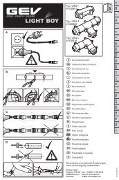
Installation<br />
If in any doubt, rather than mounting, connecting or installing the<br />
equipment yourself, contact a qualifi ed technician.<br />
The outdoor unit is designed for fl ush-mounting. Surfacemounting<br />
is possible using housing (available as an accessory). When<br />
deciding where to install the outdoor monitor, choose a position that is<br />
well protected against the elements, particularly rain. If necessary, use<br />
waterproof housing to protect the device. The camera (B7) should face<br />
upwards. Refer to the information on the optimal camera position (fi g. D).<br />
Remove the cover (fi g. F1) and install the outdoor monitor according to<br />
fi g. F2. Fit the seal so that the open ends face downwards. Carefully<br />
remove the cover (fi g. F3) to write on the label.<br />
Install the indoor monitor according to fi g. G.<br />
Connection<br />
Connect the door intercom according to fi g. H.<br />
1<br />
Connection elements<br />
Indoor monitor (fi g. C)<br />
1 Power supply connector<br />
2 Outdoor monitor 1 connection<br />
D1<br />
3 Outdoor monitor 1 connection<br />
D2<br />
4 Outdoor monitor 1 connection<br />
D3<br />
5 Outdoor monitor 1 connection<br />
D4<br />
6 Floating relay contact<br />
(Normally Open)<br />
7 Floating relay contact<br />
(Normally Open)<br />
Outdoor monitor (Fig. D)<br />
1 Indoor monitor connection C2<br />
2 Indoor monitor connection C3<br />
3 Indoor monitor connection C4<br />
4 Indoor monitor connection C5<br />
Power supply connections<br />
Connect E1 power pack plug to socket C1.<br />
Door opener<br />
The <strong>CVB</strong> door intercom provides a fl oating relay contact for connecting<br />
an electric door opener. The door opener requires its own, separate power<br />
supply. Technical data can be found on the appropriate door opener<br />
information sheet.<br />
Operation<br />
Set the ON/OFF switch A10 on the indoor monitor to ON. The LED A6 lights<br />
up green and the B6 label on the outdoor monitor also lights up. The device<br />
is now ready for use.<br />
Use switch A11 on the indoor monitor to select the required ring tone<br />
(1 to 3) or, if you do not wish to be disturbed, disable the ring tone<br />
(0 = OFF). If the ring tone is disabled, the LED A6 will light up red. Use<br />
volume adjustment A9 to set the ring tone volume independently of the<br />
general volume. Use volume adjustment A1 to set the general volume. On<br />
the outdoor monitor, set the volume using volume adjustment B5.<br />
If a visitor presses bell B3, the indoor monitor will ring. The visitor can then<br />
be seen in black & white via the outside monitor by the person inside the<br />
building. When using the device for the fi rst time, adjust the brightness and<br />
contrast (A12/A13). You can talk to the visitor by picking up the handset.<br />
Button A3 lights up when connection from the outdoor to the indoor<br />
monitor is enabled. If no buttons are pressed, connection will stop<br />
automatically after approx. 60 seconds. Press the door open button A5 to<br />
activate the (optional) door opener. Replace the handset or press button<br />
A4 to stop connection. If no buttons are pressed, communication will be<br />
automatically interrupted after approx. 60 seconds.<br />
Outside monitoring<br />
Press button A3 to monitor the respective outside area for 60 seconds.<br />
CE compliance information<br />
Using the device near electromagnetic high frequency fi elds such as radio<br />
systems, microwaves or mobile phones, or high electrostatic discharge,<br />
can interfere with device operation. Should you encounter problems,<br />
switch the power supply off and on again to restore operation.<br />
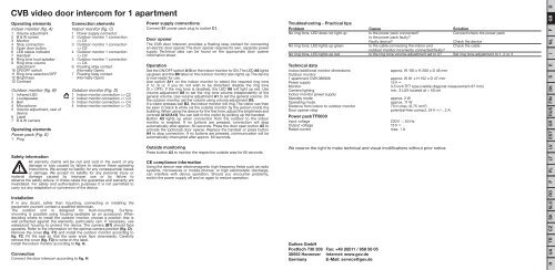
Troubleshooting - Practical tips<br />
Problem Cause Solution<br />
No ring tone, LED does not light up Is the power pack connected? Connect/check the power pack<br />
Is the power pack faulty?<br />
Faulty device? Check the device<br />
No ring tone, LED lights up green Is the cable connecting the indoor and Check the cable<br />
outdoor monitor incorrectly connected/faulty?<br />
No ring tone, LED lights up red Is the ring tone volume adjustment set to 0? Set ring tone adjustment to 1, 2 or 3<br />
Technical data<br />
Indoor/additional monitor dimensions<br />
Outdoor monitor<br />
approx. W 160 x H 200 x D 46 mm<br />
1 apartment <strong>CVB</strong> 086906 approx. W 81 x H 152 x D 47 mm<br />
Power supply 15 V<br />
Monitor 3.5 inch TFT type (visible diagonal measurement 87 mm)<br />
Camera lighting<br />
Indoor monitor power supply<br />
min. 3 LUX located at < 50 cm<br />
Standby mode approx. 2 W<br />
Operating mode approx. 11 W<br />
Distance from indoor to outdoor monitor 70 m max. (0.75 mm 2 )<br />
Door opener relay<br />
Power pack TF5000<br />
potential-free contact, 24 V /~, 2 A<br />
Input voltage 230 V ~, 50 Hz<br />
Output voltage 15 V<br />
Rated current max. 1 A<br />
We reserve the right to make technical and visual modifi cations without prior notice.<br />
Gutkes GmbH<br />
Postfach 730 308 Fax: +49 (0)511 / 958 58 05<br />
30552 Hannover Internet: www.gev.de<br />
Germany E-Mail: service@gev.de<br />
D<br />
GB<br />
F<br />
NL<br />
I<br />
E<br />
S<br />
DK<br />
FIN<br />
RUS<br />
GR<br />
EST<br />
LV<br />
LT<br />
PL<br />
P<br />
RO<br />
SLO<br />
SK<br />
CZ<br />
TR<br />
UA<br />
H