

Electret microphone replacement for a carbon insert - VMARSmanuals
Electret microphone replacement for a carbon insert - VMARSmanuals
Electret microphone replacement for a carbon insert - VMARSmanuals

Create successful ePaper yourself
Turn your PDF publications into a flip-book with our unique Google optimized e-Paper software.
The VMARS Newsletter Issue 29<br />
<strong>Electret</strong> <strong>microphone</strong> <strong>replacement</strong> <strong>for</strong> a <strong>carbon</strong> <strong>insert</strong><br />
Colin Guy G4DDI<br />
When I found that I had a dud <strong>carbon</strong> <strong>insert</strong> in an H33F/PT handset, and I couldn’t find another <strong>insert</strong> that fitted (the<br />
original is about 1” diameter) I looked around <strong>for</strong> an alternative. Trevor Sanderson’s excellent article “The RAF<br />
Microphone” (Radio Bygones issue 79/80) makes reference to the use of electret <strong>insert</strong>s with an IC preamplifier in<br />
telephones and aircraft headsets, but the in<strong>for</strong>mation given was too scant to make construction of one of these possible<br />
without reference to the IC data sheet, and the IC’s are expensive and difficult to obtain. I had a GPO type 21A <strong>insert</strong>, but<br />
the innards of this when dismantled were still too large to fit into the available space. The H33 handset is very slim, and<br />
also virtually solid, so there is very little room in which to place a preamplifier. A dig around on the internet turned up the<br />
following article written by F. Hueber, originally published in Elektor Electronics December 1994, and is published here<br />
with permission from Elektor Electronics magazine, December 1994, copyright Segment B.V., Beek (Lb.), The<br />
Netherlands, www.segment.nl. The original article included a pcb layout, but I built mine on a strip of veroboard four<br />
tracks wide by about 2” (see photo) and mounted it on the back of the ptt switch. The electret <strong>insert</strong> was acquired from a<br />
scrap telephone and all the rest of the components from TV panels. To save space the rectifier and R12 weren’t included,<br />
care being taken to ensure that the polarity was correct.<br />
Although many older telephone sets are electrically and<br />
mechanically perfectly sound units, their speech quality is<br />
poor compared with that of modern, all-electronic, sets<br />
(except the cheap types used in domestic intercoms). The<br />
reason <strong>for</strong> this deficiency is the <strong>carbon</strong> <strong>microphone</strong> in the<br />
mouthpiece. Here, an up-to-date <strong>replacement</strong> is discussed<br />
<strong>for</strong> the <strong>carbon</strong> <strong>microphone</strong>. It takes the <strong>for</strong>m of an electret<br />
<strong>microphone</strong> and an amplifier with a special band-pass<br />
characteristic.<br />
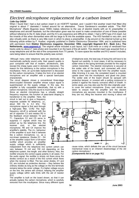
The circuit diagram shows a conventional three-stage<br />
direct-coupled transistor amplifier whose output signal is<br />
superimposed on the supply voltage. In this way, the<br />
amplifier is fully compatible (electrically, that is) with a<br />
<strong>carbon</strong> <strong>microphone</strong>. Only the sound is much better.<br />
Since an electret <strong>microphone</strong> has a virtually straight<br />
frequency response, the function of pass-band shaping is<br />
transferred to the amplifier. Here, the<br />
circuit is laid out to give a frequency<br />
response suitable <strong>for</strong> telephony, i.e.,<br />
about 500 Hz to 4.2 kHz. The<br />
<strong>microphone</strong> signal is first sent through<br />
a high-pass filter, CI-R2 The highfrequency<br />
roll-off is achieved with the<br />
aid of capacitor C3 and resistor R2 in<br />
the feedback circuit between T2 and<br />
T1. Capacitors C2 and C5 serve to<br />
suppress r.f. signals which may be<br />
picked up by the telephone line, the<br />
receiver cord, or the electret<br />
<strong>microphone</strong>. R6 and C4 improve the<br />
amplifier's stability. The d.c. behaviour<br />
of the amplifier is such that it behaves<br />
like a <strong>carbon</strong> <strong>microphone</strong>, i.e., as a<br />
non-linear resistance. Diodes D1 - D4<br />
at the amplifier output <strong>for</strong>m a full-wave<br />
rectifier which provides an amplifier<br />
supply voltage which is sufficiently<br />
independent from the telephone line current (which can<br />
vary between 15 mA and 150 mA depending on the<br />
telephone system, line length. and other factors). Also, the<br />
rectifier ensures the correct supply polarity in all cases. For<br />
the audio signal, the rectifier is simply not there since the<br />
diodes conduct as a result of the line current which flows<br />
when the receiver is lifted. The two zener diodes, D1 and<br />
D2, are included as protective devices -- they behave like<br />
ordinary diodes as long as the voltage on the line terminals<br />
remains below the zener voltage. If a higher voltage occurs<br />
on the line, the zeners still conduct, keeping the amplifier<br />
supply voltage within safe limits with the aid of resistor<br />
R12.<br />
The amplifier is built on the board shown, so that it can<br />
actually replace the <strong>carbon</strong> <strong>microphone</strong>, which is carefully<br />
removed from the mouthpiece. Since many different types<br />
of telephone exist, the best way of doing this will have to be<br />
figured out carefully. In most cases, it will be necessary to<br />
solder wires to the spring terminals provided <strong>for</strong> the original<br />
<strong>carbon</strong> transmitter. The electret <strong>microphone</strong> is secured at<br />
the solder side of the board, and connected with short<br />
wires to the copper tracks that <strong>for</strong>m the amplifier inputs.<br />
After trimming it to size, the completed board is mounted<br />
upside down into the mouthpiece, and glued into place.<br />
The solder side of the board should be sprayed with<br />
protective lacquer, or covered with a potting compound to<br />
protect it against the heavily corrosive effect of breath. In<br />
some cases, you may also use the thin disc originally used<br />
to cover the <strong>carbon</strong> <strong>microphone</strong>. Every care should be<br />
taken to ensure that the amplifier and the electret<br />
<strong>microphone</strong> are securely mounted in the mouthpiece. If<br />
they are not, lifting the receiver and moving it about will<br />
cause noise, which defeats the use of the circuit because<br />
mechanical noise is an inherent disadvantage of the old<br />
<strong>carbon</strong> <strong>microphone</strong> !<br />
[Components list is on page 16.]<br />
14 June 2003


