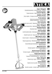
D Absauganlage GB Dust extractor FR Installation d ... - Harald Nyborg
D Absauganlage GB Dust extractor FR Installation d ... - Harald Nyborg
D Absauganlage GB Dust extractor FR Installation d ... - Harald Nyborg

Create successful ePaper yourself
Turn your PDF publications into a flip-book with our unique Google optimized e-Paper software.
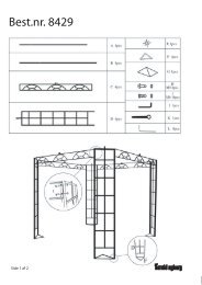
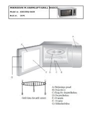
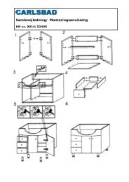
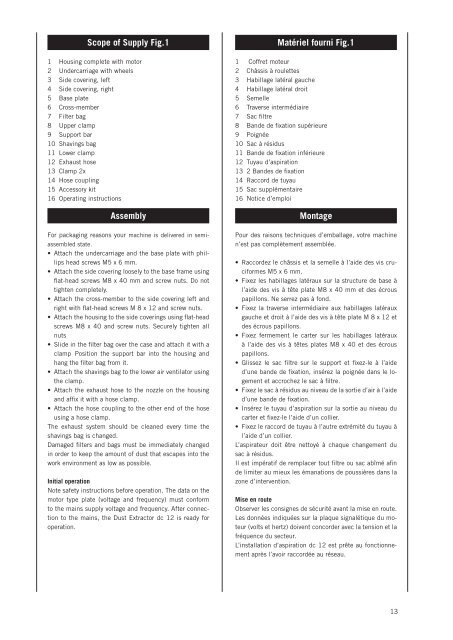
Scope of Supply Fig.1<br />
1 Housing complete with motor<br />
2 Undercarriage with wheels<br />
3 Side covering, left<br />
4 Side covering, right<br />
5 Base plate<br />
6 Cross-member<br />
7 Filter bag<br />
8 Upper clamp<br />
9 Support bar<br />
10 Shavings bag<br />
11 Lower clamp<br />
12 Exhaust hose<br />
13 Clamp 2x<br />
14 Hose coupling<br />
15 Accessory kit<br />
16 Operating instructions<br />
Assembly<br />
Matériel fourni Fig.1<br />
1 Coffret moteur<br />
2 Châssis à roulettes<br />
3 Habillage latéral gauche<br />
4 Habillage latéral droit<br />
5 Semelle<br />
6 Traverse intermédiaire<br />
7 Sac filtre<br />
8 Bande de fixation supérieure<br />
9 Poignée<br />
10 Sac à résidus<br />
11 Bande de fixation inférieure<br />
12 Tuyau d’aspiration<br />
13 2 Bandes de fixation<br />
14 Raccord de tuyau<br />
15 Sac supplémentaire<br />
16 Notice d’emploi<br />
Montage<br />
For packaging reasons your machine is delivered in semiassembled<br />
state.<br />
• Attach the undercarriage and the base plate with phillips<br />
head screws M5 x 6 mm.<br />
• Attach the side covering loosely to the base frame using<br />
flat-head screws M8 x 40 mm and screw nuts. Do not<br />
tighten completely.<br />
• Attach the cross-member to the side covering left and<br />
right with flat-head screws M 8 x 12 and screw nuts.<br />
• Attach the housing to the side coverings using flat-head<br />
screws M8 x 40 and screw nuts. Securely tighten all<br />
nuts<br />
• Slide in the filter bag over the case and attach it with a<br />
clamp Position the support bar into the housing and<br />
hang the filter bag from it.<br />
• Attach the shavings bag to the lower air ventilator using<br />
the clamp.<br />
• Attach the exhaust hose to the nozzle on the housing<br />
and affix it with a hose clamp.<br />
• Attach the hose coupling to the other end of the hose<br />
using a hose clamp.<br />
The exhaust system should be cleaned every time the<br />
shavings bag is changed.<br />
Damaged filters and bags must be immediately changed<br />
in order to keep the amount of dust that escapes into the<br />
work environment as low as possible.<br />
Initial operation<br />
Note safety instructions before operation. The data on the<br />
motor type plate (voltage and frequency) must conform<br />
to the mains supply voltage and frequency. After connection<br />
to the mains, the <strong>Dust</strong> Extractor dc 12 is ready for<br />
operation.<br />
Pour des raisons techniques d’emballage, votre machine<br />
n’est pas complètement assemblée.<br />
• Raccordez le châssis et la semelle à l’aide des vis cruciformes<br />
M5 x 6 mm.<br />
• Fixez les habillages latéraux sur la structure de base à<br />
l’aide des vis à tête plate M8 x 40 mm et des écrous<br />
papillons. Ne serrez pas à fond.<br />
• Fixez la traverse intermédiaire aux habillages latéraux<br />
gauche et droit à l’aide des vis à tête plate M 8 x 12 et<br />
des écrous papillons.<br />
• Fixez fermement le carter sur les habillages latéraux<br />
à l’aide des vis à têtes plates M8 x 40 et des écrous<br />
papillons.<br />
• Glissez le sac filtre sur le support et fixez-le à l’aide<br />
d’une bande de fixation, insérez la poignée dans le logement<br />
et accrochez le sac à filtre.<br />
• Fixez le sac à résidus au niveau de la sortie d’air à l’aide<br />
d’une bande de fixation.<br />
• Insérez le tuyau d’aspiration sur la sortie au niveau du<br />
carter et fixez-le l’aide d’un collier.<br />
• Fixez le raccord de tuyau à l’autre extrémité du tuyau à<br />
l’aide d’un collier.<br />
L’aspirateur doit être nettoyé à chaque changement du<br />
sac à résidus.<br />
Il est impératif de remplacer tout filtre ou sac abîmé afin<br />
de limiter au mieux les émanations de poussières dans la<br />
zone d’intervention.<br />
Mise en route<br />
Observer les consignes de sécurité avant la mise en route.<br />
Les données indiquées sur la plaque signalétique du moteur<br />
(volts et hertz) doivent concorder avec la tension et la<br />
fréquence du secteur.<br />
L’installation d’aspiration dc 12 est prête au fonctionnement<br />
après l’avoir raccordée au réseau.<br />
13