Sistemas de Alarme - Helmut Mauell do Brasil
Sistemas de Alarme - Helmut Mauell do Brasil
Sistemas de Alarme - Helmut Mauell do Brasil

You also want an ePaper? Increase the reach of your titles
YUMPU automatically turns print PDFs into web optimized ePapers that Google loves.
<strong>Sistemas</strong> <strong>de</strong> <strong>Alarme</strong><br />
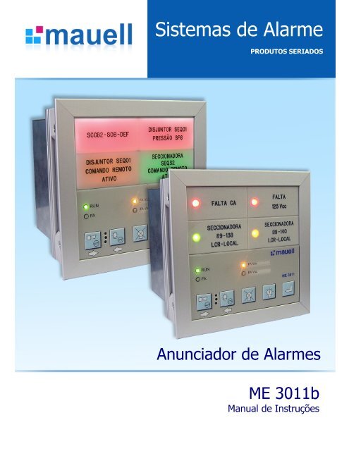
Anuncia<strong>do</strong>r <strong>de</strong> <strong>Alarme</strong>s<br />
digital<br />
ME 3011b<br />
Manual <strong>de</strong> Instruções<br />
Manual ME3011b_P_r05 1/64<br />
PRODUTOS SERIADOS
1 – Informações e da<strong>do</strong>s técnicos<br />
Introdução 4<br />
4<br />
Garantia 4<br />
5<br />
Cuida<strong>do</strong>s 5<br />
Princípios <strong>de</strong> funcionamento<br />
Da<strong>do</strong>s Técnicos 7<br />
Modularida<strong>de</strong> e formações 9<br />
Dimensões<br />
Montagem no Painel 11<br />
I<strong>de</strong>ntificação <strong>do</strong> Produto 12<br />
Codificação <strong>do</strong> Produto 13<br />
Gravações 14<br />
Seqüências <strong>de</strong> sinalização 15<br />
Opções especiais 16<br />
2 – Descrição <strong>do</strong> Produto<br />
CM-0x – CPUs Mestre 17<br />
CM-03 – CPU Mestre 2v x 4h 17<br />
CM-04 – CPU Mestre 4x x 2h 18<br />
CM-03 e CM-04 I<strong>de</strong>ntificação <strong>do</strong>s bornes 19<br />
SM-02 – CPU Escravo 20<br />
EM-02 – Módulo <strong>de</strong> expansão 2v x 4h 21<br />
EM-03 – Módulo <strong>de</strong> expansão 4v x 2h 22<br />
EM-04 – Módulo <strong>de</strong> expansão 2v x 2h 23<br />
Funções <strong>do</strong> tecla<strong>do</strong> 24<br />
Funções gerais 26<br />
3 - Instalação<br />
Fontes <strong>de</strong> alimentação 27<br />
Entradas 28<br />
Entradas <strong>de</strong> campo 28<br />
Botoeira remota 28<br />
Sincronismo com GPS (Opcional) 29<br />
Saídas 30<br />
Saída <strong>de</strong> tensão auxiliar 24Vcc 30<br />
Sirene Externa 30<br />
Saída programáveis <strong>de</strong> relés 30<br />
Saída <strong>de</strong> relés repeti<strong>do</strong>res (opcional) 31<br />
Relés repeti<strong>do</strong>res da sinalização <strong>de</strong> <strong>de</strong>tecção da alimentação 32<br />
Sincronismo <strong>de</strong> pisca (opcional) 33<br />
Recomendações 34<br />
Níveis <strong>de</strong> entradas 34<br />
Consumo 37<br />
Exemplos <strong>de</strong> esquemas <strong>de</strong> ligação 38<br />
Conexão padrão 38<br />
Conexão completa 42<br />
I<strong>de</strong>ntificação <strong>do</strong>s bornes para formações com módulo CM-03 Module 46<br />
I<strong>de</strong>ntificação <strong>do</strong>s bornes para formações com módulo CM-04 Module 48<br />
I<strong>de</strong>ntificação <strong>do</strong>s bornes para formações com módulos EM-03/EM-04 49<br />
Module I<strong>de</strong>ntificação <strong>do</strong>s bornes para as Formações especiais 51<br />
Manual ME3011b_P_r05 2/64<br />
6<br />
10
Novas formações 53<br />
Posição <strong>do</strong> módulo SM-02 nas formações 4h 54<br />
Posição <strong>do</strong> módulo SM-02 nas formações 8h 55<br />
Posição <strong>do</strong> módulo SM-02 nas formações 12h 56<br />
Posição <strong>do</strong> módulo SM-02 nas formações 16h 57<br />
Posições <strong>do</strong>s módulos nas formações especiais 58<br />
Mo<strong>do</strong>s <strong>de</strong> configuração 59<br />
4 – Software <strong>de</strong> configuração e. Tool ME3011 config 59<br />
5 – Protocolo <strong>de</strong> comunicação serial Modbus RTU 61<br />
6 – Software <strong>de</strong> visualização e.Tool ME3011 view 62<br />
7 – Software <strong>de</strong> visualização e.Tool ME3011 63<br />
Este manual está sujeito a alterações sem aviso prévio<br />
Controle <strong>de</strong> revisões<br />
Autor Revisão Data<br />
Mbe 01 10.10.07<br />
Ama 02 15.10.07<br />
Tfo 03 06.01.09<br />
Tfo 04 14.04.09<br />
lha 05 30.04.09<br />
Manual ME3011b_P_r05 3/64
Preza<strong>do</strong> (a) Cliente,<br />
A <strong>Mauell</strong> agra<strong>de</strong>ce a confiança <strong>de</strong>positada na escolha <strong>de</strong> seus produtos e com gran<strong>de</strong> satisfação<br />
fornece o Anuncia<strong>do</strong>r <strong>de</strong> <strong>Alarme</strong>s ME 3011b, integrante da consagrada família <strong>de</strong> anuncia<strong>do</strong>res<br />
<strong>Mauell</strong>.<br />
Este manual contém todas as informações necessárias para a conexão e energização <strong>do</strong> anuncia<strong>do</strong>r,<br />
bem como as instruções para a configuração <strong>do</strong> mesmo.<br />
A <strong>Mauell</strong> espera que este manual possa ajudá-lo a explorar to<strong>do</strong> o potencial <strong>do</strong> novo anuncia<strong>do</strong>r<br />
ME 3011b.<br />
Pós consultá-lo, se ainda persistir alguma dúvida sobre o funcionamento <strong>do</strong> equipamento, sinta-se à<br />
vonta<strong>de</strong> para nos contatar, pois dispomos <strong>de</strong> uma equipe técnica sempre à sua disposição, para<br />
qualquer esclarecimento complementar.<br />
Os contatos po<strong>de</strong>m ser realiza<strong>do</strong>s pelo e-mail mauell@mauell.com.br; pelo site www.mauell.com.br;<br />
pelo fax +55 11 2117 5354 ou ainda pelo telefone +55 11 2117 5353.<br />
Importante:<br />
INTRODUÇÃO<br />
Para agilizar sua consulta, tenha sempre em mãos o número <strong>de</strong> série e a versão <strong>de</strong> firmware, pois<br />
estes da<strong>do</strong>s são a chave para os esclarecimentos necessários em caso <strong>de</strong> dúvida, ou <strong>de</strong> assistência<br />
técnica.<br />
GARANTIA<br />
Os equipamentos <strong>de</strong> fabricação e fornecimento <strong>Mauell</strong> são garanti<strong>do</strong>s contra to<strong>do</strong> e qualquer <strong>de</strong>feito<br />
<strong>de</strong> projeto e fabricação, quan<strong>do</strong> submeti<strong>do</strong>s à armazenagem e utilização normal conforme suas<br />
características técnicas, pelo prazo <strong>de</strong> 12 (<strong>do</strong>ze) meses a partir <strong>de</strong> sua instalação ou <strong>de</strong> 18 (<strong>de</strong>zoito)<br />
meses conta<strong>do</strong>s da data <strong>de</strong> entrega (prevalecen<strong>do</strong> o que vencer primeiro).<br />
Durante o perío<strong>do</strong> <strong>de</strong> garantia, a <strong>Mauell</strong> substituirá ou corrigirá, sem ônus para o cliente, todas as<br />
partes <strong>do</strong> equipamento que venham a operar fora da especificação técnica. Em outras palavras, a<br />
nossa garantia cobre materiais e mão <strong>de</strong> obra para sanar eventuais <strong>de</strong>feitos elegíveis para serem<br />
cobertos pelo nosso termo <strong>de</strong> garantia.<br />
Estas operações serão realizadas em nossa se<strong>de</strong> em Itapecerica da Serra, São Paulo, para on<strong>de</strong> os<br />
equipamentos <strong>de</strong>verão ser envia<strong>do</strong>s. Para eventuais atendimentos que forçosamente <strong>de</strong>vem ser<br />
realiza<strong>do</strong>s em campo, a <strong>Mauell</strong> irá repassar os custos <strong>de</strong>correntes <strong>de</strong> transla<strong>do</strong>, hospedagem e<br />
refeições, acresci<strong>do</strong>s <strong>de</strong> uma margem administrativa, conforme comprovantes.<br />
Em caso <strong>de</strong> dúvidas sobre a utilização <strong>do</strong>s equipamentos em <strong>de</strong>corrência da garantia e seus efeitos,<br />
por favor, contate nossos <strong>de</strong>partamentos comercial e técnico.<br />
Manual ME3011b_P_r05 4/64
CUIDADOS<br />
To<strong>do</strong> anuncia<strong>do</strong>r possui uma embalagem apropriada para o transporte aéreo ou ro<strong>do</strong>viário. Ao<br />
receber o equipamento, <strong>de</strong>ve-se efetuar uma inspeção visual para verificar se houve algum dano<br />
durante o transporte. Em constatan<strong>do</strong>-se o dano, é necessário avisar imediatamente o setor <strong>de</strong><br />
recebimento <strong>de</strong> sua empresa, que <strong>de</strong>verá notificar a sua segura<strong>do</strong>ra e a <strong>Mauell</strong> para que as partes<br />
envolvidas possam a<strong>do</strong>tar as medidas necessárias para o reparo e o ressarcimento <strong>de</strong> eventuais<br />
<strong>de</strong>spesas.<br />
A Utilização incorreta e a manipulação errônea <strong>do</strong>s equipamentos não são cobertas pela garantia<br />
geral <strong>Mauell</strong>. Portanto, é imprescindível que o cliente, antes <strong>de</strong> executar a instalação e energização<br />
<strong>do</strong> equipamento tome alguns cuida<strong>do</strong>s, a seguir recomenda<strong>do</strong>s:<br />
Evitar impactos mecânicos ou quedas <strong>do</strong> equipamento que promovam abaulamento da<br />
moldura ou a quebra <strong>do</strong>s bornes traseiros.<br />
Evitar que água ou outros líqui<strong>do</strong>s escorram para <strong>de</strong>ntro <strong>do</strong> anuncia<strong>do</strong>r, provocan<strong>do</strong> curtocircuito<br />
nos componentes internos e, por conseqüência, a queima imediata <strong>do</strong> equipamento<br />
ou <strong>de</strong>feitos intermitentes no futuro.<br />
Evitar que objetos estranhos penetrem no anuncia<strong>do</strong>r através <strong>do</strong>s orifícios <strong>de</strong> ventilação;<br />
assim sen<strong>do</strong>, toda vez que for necessário efetuar algum trabalho que envolva furação ou<br />
<strong>de</strong>sbaste na chaparia <strong>do</strong> painel on<strong>de</strong> o anuncia<strong>do</strong>r estiver instala<strong>do</strong>, <strong>de</strong>ve-se proteger o<br />
equipamento com papel, plástico ou outro material para que as limalhas não penetrem no<br />
anuncia<strong>do</strong>r, provocan<strong>do</strong> mal funcionamento <strong>do</strong> mesmo.<br />
Checar os níveis <strong>de</strong> tensão e a correta i<strong>de</strong>ntificação <strong>do</strong>s cabos antes <strong>de</strong> executar a conexão<br />
<strong>do</strong> equipamento. Uma ligação errada po<strong>de</strong> provocar um curto-circuito e danificar o<br />
equipamento <strong>de</strong> maneira irreparável.<br />
Os visores frontais po<strong>de</strong>m ser removi<strong>do</strong>s com o auxílio <strong>de</strong> um estilete, que <strong>de</strong>ve ser<br />
introduzi<strong>do</strong> entre <strong>do</strong>is visores, cuida<strong>do</strong>samente, forçan<strong>do</strong> a retirada <strong>do</strong> módulo <strong>de</strong>seja<strong>do</strong>.<br />
Esta operação <strong>de</strong>ve ser efetuada com cautela e paciência que evitarão danos no frontal <strong>do</strong><br />
módulo, ou nas presilhas da gra<strong>de</strong> <strong>de</strong> fixação <strong>do</strong>s visores.<br />
A limpeza <strong>do</strong> frontal <strong>do</strong> anuncia<strong>do</strong>r po<strong>de</strong> ser realizada com um pano macio, levemente<br />
ume<strong>de</strong>ci<strong>do</strong> com um <strong>de</strong>tergente neutro. O equipamento não <strong>de</strong>ve ser submeti<strong>do</strong> a jatos<br />
diretos <strong>de</strong> líqui<strong>do</strong>s e to<strong>do</strong> cuida<strong>do</strong> <strong>de</strong>ve ser toma<strong>do</strong> para que estes não penetrem em seu<br />
interior.<br />
Manual ME3011b_P_r05 5/64
Anuncia<strong>do</strong>res <strong>de</strong> alarme têm como principal função, sinalizar corretamente esta<strong>do</strong>s críticos <strong>de</strong><br />
instalações, preservan<strong>do</strong> a integrida<strong>de</strong> das mesmas.<br />
Eles possuem sinais sonoros e visuais <strong>de</strong> alarmes numa forma padronizada.<br />
Recomenda-se, em geral, realizar a conexão direta <strong>de</strong> sinais elétricos <strong>de</strong> alarme <strong>do</strong> campo com o<br />
anuncia<strong>do</strong>r, evitan<strong>do</strong>-se a sua passagem por sistemas digitais <strong>de</strong> automação e <strong>de</strong> controle. Assim,<br />
obtém-se um nível <strong>de</strong> segurança operacional a<strong>de</strong>qua<strong>do</strong>.<br />
O comprimento máximo <strong>de</strong> cabos está <strong>de</strong>fini<strong>do</strong> <strong>de</strong> acor<strong>do</strong> com a tensão <strong>de</strong> campo. Estes valores<br />
máximos po<strong>de</strong>m ser reduzi<strong>do</strong>s em área com fortes campos eletromagnéticos, como em calhas a céu<br />
aberto em subestações. Também é <strong>de</strong> suma importância que os cabos sejam aloca<strong>do</strong>s em calhas<br />
portan<strong>do</strong> cabos com tensões homogêneas. A alocação <strong>de</strong> cabos <strong>de</strong> alta e baixa tensão na mesma<br />
calha po<strong>de</strong> causar disfunções sérias no anuncia<strong>do</strong>r ou mesmo falhas <strong>de</strong> hardware.<br />
Assim sen<strong>do</strong>, o anuncia<strong>do</strong>r ME 3011 incorpora todas as vantagens <strong>de</strong> um sistema microprocessa<strong>do</strong>,<br />
como configuração das principais funções <strong>do</strong> anuncia<strong>do</strong>r através <strong>do</strong> tecla<strong>do</strong> frontal, ou ainda via<br />
software <strong>de</strong> configuração, disponível no en<strong>de</strong>reço www.mauell.com.br, on<strong>de</strong> o cliente po<strong>de</strong>rá realizar<br />
<strong>do</strong>wnload.<br />
Desta forma, o anuncia<strong>do</strong>r apresenta todas as funções convencionais <strong>de</strong> anunciação <strong>de</strong> alarmes<br />
aliadas a novas e avançadas funções <strong>de</strong> comunicação em re<strong>de</strong> local, <strong>de</strong> registro <strong>de</strong> eventos, entre<br />
outras.<br />
Estas funções serão <strong>de</strong>scritas <strong>de</strong>talhadamente no <strong>de</strong>correr <strong>de</strong>ste manual.<br />
PRINCÍPIO DE FUNCIONAMENTO<br />
Manual ME3011b_P_r05 6/64
1 – Fontes <strong>de</strong> Alimentação<br />
2 - Entradas<br />
3 - Saídas<br />
2.1<br />
2.2<br />
2.3<br />
1.1 Fonte PS-05 24 Vcc ± 20%<br />
1.2 Fonte PS-06 (Opcional)<br />
Entrada: 19 a 264 Vcc e / ou 90 a 264 Vca<br />
Saída <strong>de</strong> tensão auxiliar: 24vcc / 0,75A<br />
1.3 Função Especial PSFD Detector <strong>de</strong> falta da tensão <strong>de</strong> alimentação para Vcc e/ou Vca<br />
1.4 Nota: Todas as fontes são integradas ao anuncia<strong>do</strong>r<br />
Entradas <strong>de</strong> alarme 4 a 252<br />
Isolação Acopla<strong>do</strong>res ópticos<br />
Tensões <strong>de</strong> entrada 24, 48, 60, 110, 125 Vcc ± 20%; 110, 127, 220 Vca ± 20%<br />
Corrente <strong>de</strong> entrada Veja tabela na pág. 35<br />
Filtro <strong>de</strong> Entrada Menor valor = 5 ms, programável em passos <strong>de</strong> 2.5 ms<br />
Botoeira externa 24vcc<br />
Isolação Acopla<strong>do</strong>res ópticos<br />
Funções<br />
3.1 Relés<br />
Sincronismo com GPS e/ou<br />
Pisca<br />
Quitação Sonora (QS), Quitação Luminosa (QL), Reset (RE), Teste<br />
Luminoso/Teste Funcional (TL/TF), Mo<strong>do</strong> <strong>de</strong>sassisti<strong>do</strong> Sleep Mo<strong>de</strong> (SLM),<br />
Tecla<strong>do</strong> <strong>de</strong>sliga<strong>do</strong> (PB OFF)<br />
24vcc<br />
Isolação Acopla<strong>do</strong>res ópticos<br />
3.2 Indicação Sonora 90 dB / 10 cm, 4 kHz<br />
3.3 Relés repeti<strong>do</strong>res (Opcional)<br />
3.4<br />
4 - Interfaces<br />
Relés repeti<strong>do</strong>res para o<br />
<strong>de</strong>tector <strong>de</strong> falta <strong>de</strong> tensão<br />
PSFD (Opcional)<br />
Nota:<br />
4.2 Comunicação RS232C (Padrão)<br />
4.3 Comunicação RS485 (Opcional)<br />
3 contatos livres <strong>de</strong> potencial, livremente programáveis para várias funções<br />
como por ex.: sirene externa, falta <strong>de</strong> tensão, grupos <strong>de</strong> alarme, live signal,<br />
watch<strong>do</strong>g etc.<br />
1 contato livre <strong>de</strong> potencial para cada ponto <strong>de</strong> entrada em grupos <strong>de</strong> 4 ou<br />
8 entradas <strong>de</strong>pen<strong>de</strong>ntes da formação, com raiz comum.<br />
Nota: Tensões acima <strong>de</strong> 125 Vcc ou Vca não admitem relés repeti<strong>do</strong>res<br />
1 contato livre <strong>de</strong> potencial para cada PSFD<br />
Capacida<strong>de</strong> <strong>de</strong> contato para to<strong>do</strong>s os relés é <strong>de</strong> 5A / 24vcc para carga<br />
resistiva<br />
Maximal switching voltage: 125Vcc/250 Vca<br />
RS232C bidirecional<br />
Baud rate: 9600,n,8,1<br />
Protocolo: Modbus RTU (Slave)<br />
Comunicação serial bidirecional (configurável)<br />
Baud rate: 100 a 19200<br />
Parida<strong>de</strong>: par, ímpar ou sem<br />
Bits <strong>de</strong> parada: 1 ou 2<br />
Protocolo: Modbus RTU (Slave)<br />
DADOS TÉCNICOS<br />
Manual ME3011b_P_r05 7/64
5 – Registro <strong>de</strong> eventos (Opcional)<br />
6 - Visualização<br />
7 – Geral<br />
5.1 Eventos 1000, com carimbo <strong>de</strong> tempo<br />
5.2 Resolução 1 ms, amostragens <strong>de</strong> ±2,5 ms<br />
5.3 Interfaces RS232C e RS485<br />
5.4 Protocolo Modbus RTU (Slave)<br />
6.1<br />
Indicação Luminosa<br />
Back light Disponível em: vermelho, amarelo, ver<strong>de</strong>, azul e branco<br />
Ultra Bright Back light (opcional) Disponível em: vermelho, amarelo, ver<strong>de</strong>, azul e branco<br />
Soquete Back Light (Opcional)<br />
Soquete Back Light Ultra Bright<br />
(Opcional)<br />
Disponível em: vermelho, amarelo, ver<strong>de</strong>, azul e branco, em<br />
soquetes que permitem a troca em campo<br />
Disponível em: vermelho, amarelo, ver<strong>de</strong>, azul e branco, em<br />
soquetes que permitem a troca em campo<br />
Led Led aparente <strong>de</strong> 5 mm em vermelho, amarelo e ver<strong>de</strong><br />
Opção Especial Mais <strong>de</strong> uma cor <strong>de</strong> visualização por anuncia<strong>do</strong>r<br />
6.2 Freqüência <strong>de</strong> pisca<br />
6.3<br />
Janelas<br />
Dimensão 24 x 48 mm<br />
Rápi<strong>do</strong>: aproximadamente 1.2 Hz<br />
Lento: aproximadamente 0.4 Hz<br />
Back light Módulos translúci<strong>do</strong>s na cor branca<br />
Led Módulos em policarbonato na cor cinza RAL7032<br />
7.1 Seqüências <strong>de</strong> <strong>Alarme</strong> ISA 1, 1A, 1B, 2A, 2C, 4A, 4AR; outras sob consulta<br />
7.2 Meio ambiente<br />
7.3 Classe <strong>de</strong> proteção<br />
Temperatura <strong>de</strong> operação: 0 a 55°C<br />
Temperatura <strong>de</strong> armazenagem: -20 a 80°C<br />
Umida<strong>de</strong> relativa: 0 to 95 %, sem con<strong>de</strong>nsação<br />
Frontal: IP41<br />
Caixa: IP30<br />
7.5 Isolação 3 kV, 60Hz, 1 min. conforme IEC60950-1<br />
7.5 Compatibilida<strong>de</strong> Magnética<br />
7.6<br />
7.7<br />
Imunida<strong>de</strong>: DIN EN 61000-6-2<br />
Emissão: DIN EN 61000-6-4<br />
ESD DIN EN 61000-4-2<br />
Imunida<strong>de</strong> a campos<br />
eletromagnéticos<br />
DIN EN 61000-4-3<br />
7.8 Imunida<strong>de</strong> a freqüências RF DIN EN 61000-4-6<br />
7.9 Burst DIN EN 61000-4-4<br />
7.10 Surge DIN EN 61000-4-5<br />
7.11 Interrupções <strong>de</strong> alimentação DIN EN 61000-4-11<br />
7.12 Terminais Borne conector (removível para cabos <strong>de</strong> até 2.5 mm²<br />
7.13 Tropicalização Opção especial<br />
DADOS TÉCNICOS<br />
Manual ME3011b_P_r05 8/64
As configurações mínimas possíveis para o anuncia<strong>do</strong>r b são os módulos centrais com 4 pontos <strong>de</strong> alarme com<br />
dimensão 2V x 4H e 4V x 2H. (veja a porção sombreada no canto direito da figura abaixo)<br />
A estes módulos centrais po<strong>de</strong>m ser adiciona<strong>do</strong>s módulos <strong>de</strong> expansão com 4 ou 8 pontos <strong>de</strong> alarme cada, sempre na<br />
formação modular 2V x 2H ou 2V x 4H. Assim, as formações subseqüentes serão <strong>de</strong> 8, 12, 16, 20, 24, 28 pontos <strong>de</strong><br />
alarme e assim por diante, até no máximo 252 pontos.<br />
A modularida<strong>de</strong> possível será conforme a figura abaixo.<br />
Número <strong>de</strong> Módulos na Vertical<br />
y = 12<br />
y = 11<br />
y = 10<br />
y = 9<br />
y = 8<br />
y = 7<br />
y = 6<br />
y = 5<br />
y = 4<br />
y = 3<br />
y = 2<br />
y = 1<br />
Nr. <strong>de</strong><br />
Pontos<br />
Formação das caixas:<br />
Nr. <strong>de</strong><br />
Nr. <strong>de</strong><br />
Nr. <strong>de</strong><br />
Formação Formação Formação Formação<br />
Pontos<br />
Pontos<br />
Pontos<br />
MODULARIDADE E FORMAÇÕES<br />
16 15 14 13 12 11 10 9 8 7 6 5 4 3 2 1<br />
16vx16h=<br />
252P<br />
14vx16h=<br />
220P<br />
12vx16h=<br />
188P<br />
10vx16h=<br />
156P<br />
8vx16h=<br />
124P<br />
6vx16h=<br />
92P<br />
4vx16h=<br />
60P<br />
2vx16h=<br />
28P<br />
4vx14h=<br />
52P<br />
2vx14h=<br />
24P<br />
20vx12h=<br />
236P<br />
18vx12h=<br />
212P<br />
16vx12h=<br />
188P<br />
14vx12h=<br />
164P<br />
12vx12h=<br />
140P<br />
10vx12h=<br />
116P<br />
8vx12h=<br />
92P<br />
6vx12h=<br />
68P<br />
4vx12h=<br />
44P<br />
2vx12h=<br />
20P<br />
Número <strong>de</strong> Pontos na Horizontal (h)<br />
6vx10h=<br />
56P<br />
4vx10h=<br />
36P<br />
2vx10h=<br />
16P<br />
24vx8h=<br />
188P<br />
22vx8h=<br />
172P<br />
20vx8h=<br />
156P<br />
18vx8h=<br />
140P<br />
16vx8h=<br />
124P<br />
14vx8h=<br />
108P<br />
12vx8h=<br />
92P<br />
10vx8h=<br />
76P<br />
8vx8h=<br />
60P<br />
Nr. <strong>de</strong><br />
Pontos<br />
Formação<br />
4<br />
4 v<br />
2 v<br />
x<br />
x<br />
2 h<br />
4 h<br />
24<br />
14 v<br />
2 v<br />
x<br />
x<br />
2 h<br />
14 h<br />
52<br />
14 v<br />
4 v<br />
x<br />
x<br />
4 h<br />
14 h<br />
84 22 v<br />
24 v<br />
x<br />
x<br />
4 h<br />
4 h<br />
164<br />
172<br />
14 v<br />
22 v<br />
x<br />
x<br />
12 h<br />
8 h<br />
8<br />
2 v<br />
6 v<br />
8 v<br />
x<br />
x<br />
x<br />
6 h<br />
2 h<br />
2 h<br />
28<br />
16 v<br />
8 v<br />
4 v<br />
x<br />
x<br />
x<br />
2 h<br />
4 h<br />
8 h<br />
56<br />
10 v<br />
6 v<br />
16 v<br />
x<br />
x<br />
x<br />
6 h<br />
10 h<br />
4 h<br />
92<br />
12 v<br />
8 v<br />
6 v<br />
x<br />
x<br />
x<br />
8 h<br />
12 h<br />
16 h<br />
188<br />
24 v<br />
16 v<br />
12 v<br />
x<br />
x<br />
x<br />
8 h<br />
12 h<br />
16 h<br />
12 4 v x 4 h 2 v x 16 h 60 8 v x 8 h 108 14 v x 8 h 212 18 v x 12 h<br />
16<br />
2 v<br />
10 v<br />
2 v<br />
x<br />
x<br />
x<br />
8 h<br />
2 h<br />
10 h<br />
32<br />
18 v<br />
6 v<br />
20 v<br />
x<br />
x<br />
x<br />
2 h<br />
6 h<br />
2 h<br />
68<br />
4 v<br />
18 v<br />
6 v<br />
x<br />
x<br />
x<br />
16 h<br />
4 h<br />
12 h<br />
116<br />
124<br />
10 v<br />
16 v<br />
8 v<br />
x<br />
x<br />
x<br />
12 h<br />
8 h<br />
16 h<br />
220<br />
236<br />
252<br />
14 v<br />
20 v<br />
16 v<br />
x<br />
x<br />
x<br />
16 h<br />
12 h<br />
16 h<br />
20<br />
12 v<br />
6 v<br />
4 v<br />
2 v<br />
x<br />
x<br />
x<br />
x<br />
2 h<br />
4 h<br />
6 h<br />
12 h<br />
36<br />
40<br />
10 v<br />
4 v<br />
22 v<br />
24 v<br />
x<br />
x<br />
x<br />
x<br />
4 h<br />
10 h<br />
2 h<br />
2 h<br />
76<br />
20 v<br />
10 v<br />
x<br />
x<br />
4 h<br />
8 h<br />
140<br />
156<br />
18 v<br />
12 v<br />
20 v<br />
10 v<br />
x<br />
x<br />
x<br />
x<br />
8 h<br />
12 h<br />
8 h<br />
16 h<br />
12 v x 4 h<br />
44 8 v x 6 h<br />
6 v x 8 h<br />
4 v x 12 h<br />
Manual ME3011b_P_r05 9/64<br />
8vx6h=<br />
44P<br />
24vx4h=<br />
92P<br />
22vx4h=<br />
84P<br />
20vx4h=<br />
76P<br />
18vx4h=<br />
68P<br />
16vx4h=<br />
60P<br />
14vx4h=<br />
52P<br />
12vx4h=<br />
44P<br />
10vx4h=<br />
36P<br />
4 3,5 3 2,5 2 1,5 1 0,5<br />
6vx8h=<br />
44P<br />
4vx8h=<br />
28P<br />
2vx8h=<br />
12P<br />
Número <strong>de</strong> Módulos na Horizontal<br />
6vx6h=<br />
32P<br />
4vx6h=<br />
20P<br />
2vx6h=<br />
8P<br />
8vx4h=<br />
28P<br />
6vx4h=<br />
20P<br />
4vx4h=<br />
12P<br />
2vx4h<br />
=4P<br />
2vx4h<br />
=4P<br />
4 3<br />
24vx2h=<br />
44P<br />
22vx2h=<br />
40P<br />
20vx2h=<br />
36P<br />
18vx2h=<br />
32P<br />
16vx2h=<br />
28P<br />
14vx2h=<br />
24P<br />
12vx2h=<br />
20P<br />
10vx2h=<br />
16P<br />
8vx2h=<br />
12P<br />
6vx2h=<br />
8P<br />
4vx2h<br />
=4P<br />
CM-0x<br />
CM-03<br />
24<br />
23<br />
22<br />
21<br />
20<br />
19<br />
18<br />
17<br />
16<br />
15<br />
14<br />
13<br />
12<br />
11<br />
10<br />
9<br />
8<br />
7<br />
6<br />
5<br />
4<br />
3<br />
2<br />
1<br />
Número <strong>de</strong> Pontos na Vertical (v)<br />
4vx2h<br />
=4P<br />
CM-04<br />
4<br />
Minimal<br />
arrangement
v<br />
(y)<br />
Points<br />
Recorte no painel:<br />
2 4 6 8<br />
Tabela <strong>de</strong> Furação <strong>do</strong> Painel [altura(v) x largura (h)] mm<br />
DIMENSÕES<br />
2 65 x 209 65 x 305 65 x 401 65 x 497 65 x 593 65 x 785<br />
4 113 x 113 113 x 209 113 x 305 113 x 401 113 x 497 113 x 593 113 x 689 113 x 785<br />
6 161 x 113 161 x 209 161 x 305 161 x 401 161 x 497 161 x 593 161 x 785<br />
8 209 x 113 209 x 209 209 x 305 209 x 401 209 x 593 209 x 785<br />
10 257 x 113 257 x 209 257 x 305 257 x 401 257 x 593 257 x 785<br />
12 305 x 113 305 x 209 305 x 401 305 x 593 305 x 785<br />
14 353 x 113 353 x 209 353 x 401 353 x 593 353 x 785<br />
16 401 x 113 401 x 209 401 x 401 401 x 593 401 x 785<br />
18 449 x 113 449 x 209 449 x 401 449 x 593<br />
20 497 x 113 497 x 209 497 x 401 497 x 593<br />
22 545 x 113 545 x 209 545 x 401 545 x 593<br />
24 593 x 113 593 x 209 593 x 401<br />
Manual ME3011b_P_r05 10/64<br />
h (x)<br />
10 12 14<br />
16
Cada ME 3011b é forneci<strong>do</strong> com uma <strong>de</strong>terminada quantida<strong>de</strong> <strong>de</strong> fixa<strong>do</strong>res <strong>de</strong> acor<strong>do</strong> com o tamanho <strong>do</strong> anuncia<strong>do</strong>r.<br />
1 – Localize os fixa<strong>do</strong>res na embalagem<br />
2 – Insira o anuncia<strong>do</strong>r na furação <strong>do</strong> painel<br />
3 – Insira os fixa<strong>do</strong>res na moldura, selecionan<strong>do</strong> a posição que propicie a melhor fixação<br />
4 – Aparafuse os fixa<strong>do</strong>res levemente contra o painel.<br />
Fixa<strong>do</strong>r<br />
MONTAGEM NO PAINEL<br />
Manual ME3011b_P_r05 11/64
1 – Etiqueta <strong>de</strong> I<strong>de</strong>ntificação<br />
1.1 Código<br />
Código <strong>do</strong> produto com 15 dígitos<br />
1.2 Serial#<br />
Número <strong>de</strong> série <strong>do</strong> produto AA/b9999, on<strong>de</strong> AA é o ano e 9999 é um número seqüencial<br />
1.3 FW:<br />
I<strong>de</strong>ntifica a versão <strong>de</strong> Firmware <strong>do</strong> anuncia<strong>do</strong>r<br />
1.4 Power Supply:<br />
Tensões <strong>de</strong> Alimentação<br />
Padrão:<br />
19-264vdc/90-264vac<br />
Ou<br />
Com <strong>de</strong>tector <strong>de</strong> falta <strong>de</strong> tensão PSFD são especificadas as tensões a serem supervisionadas, solicitadas na<br />
encomenda <strong>do</strong> produto.<br />
Exemplo com as tensões especificadas <strong>de</strong> 125vcc e 220vca:<br />
19-264vdc/90-264vac(125vdc/220vac)<br />
Indica que a fonte é universal, e as tensões supervisionadas para indicar falta são:<br />
125vcc e 220VCA são os valores que aparecem entre parênteses.<br />
1.5 Field:<br />
Indica a tensão <strong>de</strong> campo <strong>do</strong> anuncia<strong>do</strong>r<br />
Power Supply: 19-264Vdc 90-264Vac (125Vdc/220Vac)<br />
<strong>Helmut</strong> <strong>Mauell</strong> <strong>do</strong> <strong>Brasil</strong><br />
www.mauell.com.br<br />
Alarm Annunciator<br />
Co<strong>de</strong>: 004424D11612000<br />
FW:<br />
4.xx.x Field: 24 Vdc<br />
Indústria <strong>Brasil</strong>eira / Ma<strong>de</strong> in Brazil / Fabriqué au Brésil<br />
IDENTIFICAÇÃO DO PRODUTO<br />
Serial #: 07/b1001<br />
Manual ME3011b_P_r05 12/64
O Gera<strong>do</strong>r <strong>de</strong> Códigos para o ME3011b po<strong>de</strong> ser baixa<strong>do</strong> no seguinte site:<br />
http://www.mauell.com.br/site2008/<strong>do</strong>wnloads.html (Me3011b Co<strong>de</strong> Generator)<br />
CODIFICAÇÃO DO PRODUTO<br />
Manual ME3011b_P_r05 13/64
1 – Gravação em baixo relevo<br />
1.1 – Visor Back Light<br />
LB 24 x 48 – Cor Branca Translúcida - Código: 83.53.002<br />
Altura da Fonte = 3 mm Número máximo <strong>de</strong> caracteres por linha = 19 Número máximo <strong>de</strong> linhas = 4<br />
24<br />
23<br />
*Para melhor visualização recomenda-se o uso <strong>de</strong> 03 linhas para o enuncia<strong>do</strong>.<br />
1.2 – Visor LED<br />
MK 24 x 48 - Cor RAL 7032 - Código: 83.52.003<br />
Altura da Fonte = 3 mm Número máximo <strong>de</strong> caracteres por linha = 15 Número máximo <strong>de</strong> linhas = 4<br />
23,5<br />
24<br />
ABCDEFGHJKLMNOPRSTU<br />
ABCDEFGHJKLM<br />
ABCDEFGH<br />
EFGH<br />
47<br />
48<br />
ABCDEFGHJKLMNOP<br />
ABCDEFGH<br />
ABCDEFGHJKLMNOP<br />
ABCDEFGH<br />
47,5<br />
48<br />
*Para melhor visualização recomenda-se o uso <strong>de</strong> 03 linhas para a inscrição.<br />
5<br />
5<br />
5<br />
4<br />
5<br />
5<br />
5<br />
4<br />
ABCDEFGHJKLMNOPRSTU<br />
ABCDEFGHJKLM<br />
ABCDEFGH<br />
Manual ME3011b_P_r05 14/64<br />
24<br />
24<br />
23<br />
23,5<br />
INSCRIÇÃO NO VISOR<br />
47<br />
48<br />
ABCDEFGHJKLMNOP<br />
ABCDEFGH<br />
ABCDEFGHJKLMNOP<br />
47,5<br />
48<br />
5,5<br />
6<br />
6<br />
6<br />
6<br />
6
O anuncia<strong>do</strong>r ME3011B po<strong>de</strong> ser configura<strong>do</strong> para até 16 seqüências <strong>de</strong> sinalização, das quais as mais importantes são<br />
seguintes, segun<strong>do</strong> as Normas:<br />
ISA-RP 18.1 / (ISA-S18. 1):<br />
ISA1/(A), ISA-1A/(A-5), ISA-1B/(A-4), ISA-2A/(R-8), ISA-2C/M), ISA-4A/(F1A), ISA-4AR/(F1M), etc.<br />
Outras seqüências, sob consulta.<br />
REF ISA<br />
ISA 1<br />
ISA 1A<br />
ISA 1B<br />
ISA 2A<br />
ISA 2C<br />
(<strong>de</strong>fault)<br />
ISA 4A<br />
ISA 4R<br />
ALARME NORMAL<br />
Luminoso<br />
Sonoro<br />
Luminoso<br />
Sonoro<br />
Luminoso<br />
Sonoro<br />
Luminoso<br />
Sonoro<br />
Luminoso<br />
Sonoro<br />
Luminoso<br />
Sonoro<br />
Luminoso<br />
Sonoro<br />
ANORMAL<br />
SEQÜÊNCIA DE ALARME<br />
SEQÜÊNCIAS DE SINALIZAÇÃO<br />
RETORNO AO<br />
QUITAÇÃO RETORNO<br />
QUITAÇÃO<br />
NORMAL<br />
AO<br />
ANTES DA<br />
SONORA LUMINOSA NORMAL<br />
QUITAÇÃO SONORA LUMINOSA<br />
R R L R R L<br />
SEQÜÊNCIA DE SINAL PRIMÁRIO (1° Evento)<br />
REF ISA ALARME NORMAL<br />
ANORMAL QUITAÇÃO<br />
RETORNO AO<br />
NORMAL<br />
RETORNO AO NORMAL<br />
ANTES DA QUITAÇÃO QUITAÇÃO<br />
RESET<br />
INICIAL SUBSEQ. INICIAL SUBSEQ. INICIAL SUBSEQ. INICIAL SUBSEQ. INICIAL SUBSEQ.<br />
LEGENDA<br />
R Rápi<strong>do</strong> Led apaga<strong>do</strong> Sirene <strong>de</strong>sligada<br />
L Lento Led aceso Sirene ligada<br />
Led intermitente<br />
Manual ME3011b_P_r05 15/64<br />
RESET
Opções Especiais são aquelas para as quais o cliente <strong>de</strong>ve informar da<strong>do</strong>s para que os anuncia<strong>do</strong>res<br />
possam ser fabrica<strong>do</strong>s.<br />
1 – Indicação luminosa com mais <strong>de</strong> uma cor<br />
A quantida<strong>de</strong> <strong>de</strong> cada cor e sua disposição no anuncia<strong>do</strong>r <strong>de</strong>ve ser informada pelo cliente<br />
Para indicação LED – até 3 cores (vermelho / amarelo / ver<strong>de</strong>)<br />
Para Back Light / Ultra Bright Back Light – até cinco cores (vermelho / amarelo / ver<strong>de</strong> / branco e azul)<br />
O cliente <strong>de</strong>verá fornecer um <strong>de</strong>senho com a disposição das cores <strong>do</strong>s LEDs.<br />
2 – Soquetes BL<br />
A sinalização para anuncia<strong>do</strong>res com Back Light / Ultra Bright Back Light po<strong>de</strong> ser fornecida na versão soquetada, o<br />
que permite alterar em campo a cor da sinalização.<br />
O soquete BL <strong>de</strong>ve ser especifica<strong>do</strong> na solicitação <strong>do</strong> equipamento, bem como as cores e quantida<strong>de</strong> <strong>de</strong> cada cor.<br />
O cliente <strong>de</strong>verá fornecer um <strong>de</strong>senho com a disposição das cores <strong>do</strong>s LEDs.<br />
3 – Tropicalização<br />
O produto será tropicaliza<strong>do</strong> se assim for solicita<strong>do</strong> no ato da compra, com um custo adicional.<br />
O cliente <strong>de</strong>verá fornecer solicitar esta opção no ato da compra.<br />
4 – PSFD “Power Supply Fault Detector”<br />
OPÇÕES ESPECIAIS<br />
O <strong>de</strong>tector <strong>de</strong> falha na tensão <strong>de</strong> alimentação atua quan<strong>do</strong> a tensão <strong>de</strong> alimentação for 20% menor que a tensão<br />
Nominal.<br />
Existem duas formas <strong>de</strong> visualizar esta indicação:<br />
� Padrão:<br />
o A falha <strong>de</strong> Vcc é indicada no LED amarelo <strong>do</strong> tecla<strong>do</strong><br />
o A falha <strong>de</strong> Vca é indicada no LED laranja <strong>do</strong> tecla<strong>do</strong><br />
� Opcional:<br />
o A falha <strong>de</strong> Vcc é indicada no ponto <strong>de</strong> alarme 2<br />
o A falha <strong>de</strong> Vca é indicada no ponto <strong>de</strong> alarme 4<br />
Os relés repeti<strong>do</strong>res para esta função se encontram no conector C3, sen<strong>do</strong> que a tensão <strong>de</strong> contato <strong>de</strong>stes relés se<br />
Encontra no conector C2-5<br />
As tensões nominais para Vcc e/ou Vca <strong>de</strong>vem ser informa<strong>do</strong>s no ato da compra <strong>do</strong> anuncia<strong>do</strong>r, bem<br />
Como a posição da indicação Luminosa.<br />
Manual ME3011b_P_r05 16/64
1 - CM-0x - “Central Module” - CPU Mestre com 4 pontos <strong>de</strong> <strong>Alarme</strong><br />
O módulo CPU mestre é responsável pelo gerenciamento <strong>do</strong>s módulos escravos, pela interface homem-máquina para o<br />
reconhecimento <strong>de</strong> alarmes, configuração <strong>do</strong> anuncia<strong>do</strong>r, sinalização sonora, sinalização luminosa e estada operacional<br />
<strong>do</strong> mesmo.<br />
O anuncia<strong>do</strong>r possui, como opção, uma interface RS485 com protocolo Modbus RTU propician<strong>do</strong> a interligação <strong>de</strong><br />
diversos conjuntos anuncia<strong>do</strong>res em uma re<strong>de</strong>, bem como CLPs, UTRs e software supervisório.<br />
Cada microcontrola<strong>do</strong>r mantém armazena<strong>do</strong> o esta<strong>do</strong> das entradas sob seu processamento e a configuração <strong>do</strong><br />
anuncia<strong>do</strong>r, permitin<strong>do</strong> a restauração da situação operacional em ocorren<strong>do</strong> queda <strong>de</strong> energia.<br />
A CPU Mestre po<strong>de</strong> controlar diretamente até 60 pontos <strong>de</strong> alarme e até 3 CPUs Escravas, perfazen<strong>do</strong> 252 pontos,<br />
sen<strong>do</strong> que a comunicação entre elas é feita serialmente, através <strong>de</strong> um barramento interno <strong>de</strong> duas vias, segun<strong>do</strong><br />
padrão assíncrono.<br />
A configuração manual <strong>do</strong> equipamento é realizada através <strong>do</strong>s 5 botões da CPU pela Configuração via tecla<strong>do</strong> ou pelo<br />
software e.Tool config<br />
� CM-03 – Central Module com formação 2v x 4h<br />
� CM-04– Central Module com formação 4v x 2h<br />
Os módulos centrais possuem como padrão:<br />
Entradas:<br />
� Alimentação<br />
� Botoeira remota<br />
� 4 entradas <strong>de</strong> alarme com negativo comum<br />
� Interface RS232C<br />
Saídas:<br />
� Tensão auxiliar <strong>de</strong> 24Vdc/0,75A,<br />
� 3 relés programáveis livres <strong>de</strong> potencial<br />
Como opcionais:<br />
Entradas:<br />
� RS485<br />
� Sincronismo com GPS e/ou sincronismo <strong>de</strong> pisca<br />
Saídas:<br />
DESCRIÇÃO DO PRODUTO – MÓDULO CM-0x<br />
� 4 relés repeti<strong>do</strong>res com raiz comum<br />
� 1 ou 2 relés repeti<strong>do</strong>res com raiz comum para a indicação <strong>de</strong> Falta Vcc e/ou Falta Vca<br />
Manual ME3011b_P_r05 17/64
1.1 DESCRIÇÃO DO PRODUTO – MÓDULO CM-03<br />
Vdc Fault<br />
Vac Fault<br />
Balanceamento RS 485:<br />
Extrair o frontal <strong>do</strong> ponto <strong>de</strong> alarme 4 e inserir os jumpers:<br />
� JP1 e JP2 fecha<strong>do</strong>s, para o último anuncia<strong>do</strong>r da re<strong>de</strong>.<br />
� JP1 e JP2 abertos para to<strong>do</strong>s anuncia<strong>do</strong>res intermediários da re<strong>de</strong>.<br />
Opcionais<br />
Vista frontal<br />
Vista traseira<br />
Nota:<br />
A blindagem <strong>do</strong> cabo <strong>do</strong><br />
Modbus <strong>de</strong>ve ser aterrada<br />
Manual ME3011b_P_r05 18/64<br />
b
Balanceamento RS 485:<br />
Extrair o frontal <strong>do</strong> ponto <strong>de</strong> alarme 4 e inserir os jumpers:<br />
� JP1 e JP2 fecha<strong>do</strong>s, para o último anuncia<strong>do</strong>r da re<strong>de</strong>.<br />
� JP1 e JP2 abertos para to<strong>do</strong>s anuncia<strong>do</strong>res intermediários da re<strong>de</strong>.<br />
1.2 DESCRIÇÃO DO PRODUTO - MÓDULO CM-04<br />
Vista traseira<br />
OPCIONAIS<br />
Vdc Fault<br />
Vac Fault<br />
Nota:<br />
A blindagem <strong>do</strong> cabo <strong>do</strong> Modbus<br />
<strong>de</strong>ve ser aterrada<br />
Vista Frontal<br />
Manual ME3011b_P_r05 19/64<br />
b
DESCRIÇÃO DOS MÓDULOS CM-0x<br />
Manual ME3011b_P_r05 20/64
2 - SM-02 - “Slave Module” - Módulo CPU Escravo com 8 pontos <strong>de</strong> alarme<br />
DESCRIÇÃO DOS MÓDULOS SM-02<br />
Cada módulo CPU Escravo po<strong>de</strong> controlar até 64 pontos <strong>de</strong> alarme sen<strong>do</strong> utiliza<strong>do</strong> quan<strong>do</strong> o número <strong>de</strong> pontos <strong>de</strong><br />
alarme for maior que 60. Para configurações <strong>de</strong> 62 a 128 pontos utiliza-se um módulo CPU Escravo, <strong>de</strong> 130 a 188 <strong>do</strong>is<br />
módulos e <strong>de</strong> 190 a 252, três.<br />
Este módulo possui entrada <strong>de</strong> alimentação, uma saída <strong>de</strong> tensão auxiliar <strong>de</strong> 24VDC/0,75A, 8 entradas com negativo<br />
comum e opcionalmente 8 relés repeti<strong>do</strong>res com raiz comum.<br />
I<strong>de</strong>ntificação <strong>do</strong>s Conectores da CPU Escravo - SM-02<br />
OPCIONAIS<br />
Régua Conector Borne Obs. Função I<strong>de</strong>ntificação<br />
X..<br />
CX1<br />
CX2<br />
C1<br />
C2<br />
1 Vca Alimentação Vca X.. - CX1 - 1<br />
2 Vca Alimentação Vcay X.. - CX1 - 2<br />
Entrada <strong>de</strong><br />
Alimentação<br />
(1)<br />
3 Shield Shield<br />
4 + Vcc Alimentação + Vcc X.. - CX1 - 4<br />
5 - Vcc Alimentação - Vcc X.. - CX1 - 5<br />
1<br />
2<br />
Saída <strong>de</strong> + 24 Vcc<br />
Tensão - 24 Vcc<br />
Saída <strong>de</strong> tensão auxiliar<br />
X.. - CX2 - 1<br />
X.. - CX2 - 2<br />
1 Entrada + Entrada <strong>de</strong> <strong>Alarme</strong> 1 X.. - C1 - 1<br />
2 Entrada + Entrada <strong>de</strong> <strong>Alarme</strong> 2 X.. - C1 - 2<br />
3 Entrada + Entrada <strong>de</strong> <strong>Alarme</strong> 3 X.. - C1 - 3<br />
4 Entrada + Entrada <strong>de</strong> <strong>Alarme</strong> 4 X.. - C1 - 4<br />
5 Entrada + Entrada <strong>de</strong> <strong>Alarme</strong> 5 X.. - C1 - 5<br />
6 Entrada + Entrada <strong>de</strong> <strong>Alarme</strong> 6 X.. - C1 - 6<br />
7 Entrada + Entrada <strong>de</strong> <strong>Alarme</strong> 7 X.. - C1 - 7<br />
8 Entrada + Entrada <strong>de</strong> <strong>Alarme</strong> 8 X.. - C1 - 8<br />
9 Comum - Comum das Entradas <strong>de</strong> Alame (-) X.. - C1 - 9<br />
1 Relé Repeti<strong>do</strong>r da Entrada 1 (+) X.. - C2 - 1<br />
2 Relé Repeti<strong>do</strong>r da Entrada 2 (+) X.. - C2 - 2<br />
3 Relé Repeti<strong>do</strong>r da Entrada 3 (+) X.. - C2 - 3<br />
4 Relé Repeti<strong>do</strong>r da Entrada 4 (+) X.. - C2 - 4<br />
5 Relé Repeti<strong>do</strong>r da Entrada 5 (+) X.. - C2 - 5<br />
6 Relé Repeti<strong>do</strong>r da Entrada 6 (+) X.. - C2 - 6<br />
7 Relé Repeti<strong>do</strong>r da Entrada 7 (+) X.. - C2 - 7<br />
8 Relé Repeti<strong>do</strong>r da Entrada 8 (+) X.. - C2 - 8<br />
9 (+) TCont. Tensão <strong>de</strong> Contato <strong>do</strong>s relés (+) X.. - C2 - 9<br />
Entradas <strong>de</strong> <strong>Alarme</strong><br />
RRO (1)<br />
(1)<br />
(2)<br />
A alimentação <strong>do</strong> módulo SM-02 <strong>de</strong>ve ser idêntica à da CPU CM-0x, caso<br />
isto não ocorra, po<strong>de</strong> causar danos ao equipamento.<br />
Opcional<br />
Vista frontal<br />
Vista traseira<br />
Manual ME3011b_P_r05 21/64
3 - EM-0x – “Expansion Module” – Módulos <strong>de</strong> expansão.<br />
DESCRIÇÃO DOS MÓDULOS DE EXPANSÃO - EM-0x<br />
3.1 - EM-02 – Módulo <strong>de</strong> expansão com 8 pontos <strong>de</strong> <strong>Alarme</strong> na formação 2v x 4h.<br />
Este módulo possui 8 entradas <strong>de</strong> alarme com negativo comum e opcionalmente 8 relés repeti<strong>do</strong>res com raiz<br />
comum.<br />
C1<br />
C2<br />
Vista frontal<br />
Vista traseira<br />
I<strong>de</strong>ntificação <strong>do</strong>s Conectores da Expansão EM-02<br />
OPTIONS<br />
Régua Conector Borne Obs. Função<br />
I<strong>de</strong>ntificação<br />
X..<br />
1 Entrada + Entrada <strong>de</strong> <strong>Alarme</strong> 1 X.. - C1 - 1<br />
2 Entrada + Entrada <strong>de</strong> <strong>Alarme</strong> 2 X.. - C1 - 2<br />
3 Entrada + Entrada <strong>de</strong> <strong>Alarme</strong> 3 X.. - C1 - 3<br />
4 Entrada + Entrada <strong>de</strong> <strong>Alarme</strong> 4 X.. - C1 - 4<br />
5 Entrada + Entrada <strong>de</strong> <strong>Alarme</strong> 5 X.. - C1 - 5<br />
6 Entrada + Entrada <strong>de</strong> <strong>Alarme</strong> 6 X.. - C1 - 6<br />
7 Entrada + Entrada <strong>de</strong> <strong>Alarme</strong> 7 X.. - C1 - 7<br />
8 Entrada + Entrada <strong>de</strong> <strong>Alarme</strong> 8 X.. - C1 - 8<br />
9 Comum - Comum das Entradas <strong>de</strong> Alame (-) X.. - C1 - 9<br />
1 Relé Repeti<strong>do</strong>r da Entrada 1 (+) X.. - C2 - 1<br />
2 Relé Repeti<strong>do</strong>r da Entrada 2 (+) X.. - C2 - 2<br />
3 Relé Repeti<strong>do</strong>r da Entrada 3 (+) X.. - C2 - 3<br />
4 Relé Repeti<strong>do</strong>r da Entrada 4 (+) X.. - C2 - 4<br />
5 Relé Repeti<strong>do</strong>r da Entrada 5 (+) X.. - C2 - 5<br />
6 Relé Repeti<strong>do</strong>r da Entrada 6 (+) X.. - C2 - 6<br />
7 Relé Repeti<strong>do</strong>r da Entrada 7 (+) X.. - C2 - 7<br />
8 Relé Repeti<strong>do</strong>r da Entrada 8 (+) X.. - C2 - 8<br />
9 (+) TCont. Tensão <strong>de</strong> Contato <strong>do</strong>s relés (+) X.. - C2 - 9<br />
Entradas <strong>de</strong> <strong>Alarme</strong><br />
RRO (1)<br />
(1)<br />
Opcional<br />
Manual ME3011b_P_r05 22/64
3.2 - EM-03 – Módulo <strong>de</strong> Expansão com 8 entradas <strong>de</strong> alarme, na formação 4v x 2h<br />
Este módulo possui <strong>do</strong>is grupos <strong>de</strong> 4 entradas <strong>de</strong> alarme com negativo comum e opcionalmente 2 grupos <strong>de</strong> 4 relés<br />
repeti<strong>do</strong>res com raiz comum.<br />
Vista frontal<br />
DESCRIÇÃO DO PRODUTO – MÓDULOS DE EXPANSÃO EM-0x<br />
I<strong>de</strong>ntificação <strong>do</strong>s Conectores da Expansão - EM-03<br />
OPTIONS<br />
Régua Connector Term. Obs. Function<br />
I<strong>de</strong>ntificação<br />
X..<br />
X..+1<br />
C1<br />
C2<br />
C3<br />
C4<br />
1 Entrada + Entrada <strong>de</strong> <strong>Alarme</strong> 1 X.. - C1 - 1<br />
2 Entrada + Entrada <strong>de</strong> <strong>Alarme</strong> 2 X.. - C1 - 2<br />
Entradas <strong>de</strong><br />
<strong>Alarme</strong><br />
1 - 4<br />
Vista traseira<br />
3 Entrada + Entrada <strong>de</strong> <strong>Alarme</strong> 3 X.. - C1 - 3<br />
4 Entrada + Entrada <strong>de</strong> <strong>Alarme</strong> 4 X.. - C1 - 4<br />
5 Comum - Comum das Entradas <strong>de</strong> <strong>Alarme</strong> (-) X.. - C1 - 5<br />
1 Relé Relé Repeti<strong>do</strong>r da Entrada 1 (+) X.. - C2 - 1<br />
2 Relé Relé Repeti<strong>do</strong>r da Entrada 2 (+) X.. - C2 - 2<br />
3 Relé Relé Repeti<strong>do</strong>r da Entrada 3 X.. - C2 - 3<br />
4 Relé Relé Repeti<strong>do</strong>r da Entrada 4 (+) X.. - C2 - 4<br />
5 TCont. (+) Tensão <strong>de</strong> contato para os repeti<strong>do</strong>res 1-4 (+) X.. - C2 - 5<br />
1 Entrada + Entrada <strong>de</strong> <strong>Alarme</strong> 5 X.. - C3 - 1<br />
2 Entrada + Entrada <strong>de</strong> <strong>Alarme</strong> 6 X.. - C3 - 2<br />
3 Entrada + Entrada <strong>de</strong> <strong>Alarme</strong> 7 X.. - C3 - 3<br />
4 Entrada + Entrada <strong>de</strong> <strong>Alarme</strong> 8 X.. - C3 - 4<br />
5 Comum - Comum das Entradas <strong>de</strong> <strong>Alarme</strong> (-) X.. - C3 - 5<br />
1 Relé Input 5 repeat relay (+) X.. - C4 - 1<br />
2 Relé Input 6 repeat relay (+) X.. - C4 - 2<br />
3 Relé Input 7 repeat relay (+) X.. - C4 - 3<br />
4 Relé Input 8 repeat relay (+) X.. - C4 - 4<br />
5 TCont. (+) Tensão <strong>de</strong> contato para os repeti<strong>do</strong>res 5-8 (+) X.. - C4 - 5<br />
RRO 1 - 4 (1)<br />
Entrada <strong>de</strong><br />
<strong>Alarme</strong>s<br />
5 - 8<br />
RRO (1) 5 - 8<br />
(1) Opcional<br />
Manual ME3011b_P_r05 23/64
3.3- EM-04 – Módulo <strong>de</strong> expansão com 4 pontos <strong>de</strong> alarme na formação 2v x 2h<br />
Vista frontal<br />
DESCRIÇÃO DO PRODUTO – MÓDULOS DE EXPANSÃO EM-0x<br />
Este módulo possui 4 entradas <strong>de</strong> alarme com negativo comum e opcionalmente 4 relés repeti<strong>do</strong>res com raiz comum.<br />
I<strong>de</strong>ntificação <strong>do</strong>s Conectores da Expansão - EM-04<br />
OPTIONS<br />
Vista traseira<br />
Régua Connector<br />
Term. Obs. Function I<strong>de</strong>ntificação<br />
X..<br />
C1<br />
C2<br />
1 Entrada + Entrada <strong>de</strong> <strong>Alarme</strong> 1 X.. - C1 - 1<br />
2 Entrada + Entrada <strong>de</strong> <strong>Alarme</strong> 2 X.. - C1 - 2<br />
Entradas <strong>de</strong><br />
<strong>Alarme</strong><br />
3 Entrada + Entrada <strong>de</strong> <strong>Alarme</strong> 3 X.. - C1 - 3<br />
4 Entrada + Entrada <strong>de</strong> <strong>Alarme</strong> 4 X.. - C1 - 4<br />
5 Comum - Comum das Entradas <strong>de</strong> <strong>Alarme</strong> (-) X.. - C1 - 5<br />
1 Relé Relé Repeti<strong>do</strong>r da Entrada 1 (+) X.. - C2 - 1<br />
2 Relé Relé Repeti<strong>do</strong>r da Entrada 2 (+) X.. - C2 - 2<br />
3 Relé Relé Repeti<strong>do</strong>r da Entrada 3 X.. - C2 - 3<br />
4 Relé Relé Repeti<strong>do</strong>r da Entrada 4 (+) X.. C2 - 4<br />
5 TCont. (+) Tensão <strong>de</strong> contato para os repeti<strong>do</strong>res 1-4 (+) X.. - C2 - 5<br />
RRO (1)<br />
Manual ME3011b_P_r05 24/64
1 – Funções <strong>do</strong> Tecla<strong>do</strong><br />
FA<br />
LED vermelho com luz contínua<br />
indica que o sistema está com<br />
falha<br />
1.1. - Quitação Sonora (QS)<br />
A quitação sonora é realizada através <strong>de</strong> botão no frontal das CPUs. A sua atuação cala a sirene.<br />
1.2. - Quitação Luminosa (QL)<br />
A quitação luminosa é realizada através <strong>de</strong> botão no frontal da CPU que, quan<strong>do</strong> atua<strong>do</strong>, faz com que a sinalização<br />
luminosa intermitente (pisca-pisca) passe para fixa ou apagada, <strong>de</strong>pen<strong>de</strong>n<strong>do</strong> da seqüência selecionada.<br />
Nota sobre Quitação Sonora e Luminosa:<br />
As funções <strong>de</strong> quitação sonora e luminosa po<strong>de</strong>m ser atuadas manualmente, como <strong>de</strong>scrito acima, ou<br />
automaticamente, com os perío<strong>do</strong>s <strong>de</strong> tempos ajustáveis <strong>de</strong> 5 s até 45 horas.<br />
Os botões <strong>de</strong> quitação sonora e luminosa po<strong>de</strong>m ser configura<strong>do</strong>s para atuação simultânea ou <strong>de</strong> maneira a ter um<br />
inter travamento entre eles, isto é, a função <strong>de</strong> quitação luminosa só é aceita após a quitação sonora.<br />
Ver <strong>de</strong>talhes no capítulo <strong>de</strong> configuração <strong>do</strong> anuncia<strong>do</strong>r<br />
1.3. - Reset (RE)<br />
QS<br />
Quitação Sonora<br />
O reset da seqüência é feito através <strong>de</strong> botão no frontal <strong>do</strong> módulo CPU que, quan<strong>do</strong> atua<strong>do</strong>, rearma (inicializa) a<br />
seqüência <strong>de</strong> alarme.<br />
Depen<strong>de</strong>n<strong>do</strong> da seqüência selecionada o botão Reset é <strong>de</strong>sabilita<strong>do</strong><br />
1.4. - Teste Luminoso (TL)<br />
DESCRIÇÃO DAS FUNÇÕES DO TECLADO<br />
RUN<br />
- LED ver<strong>de</strong> com luz contínua indica que o sistema está operan<strong>do</strong><br />
- LED ver<strong>de</strong> com luz piscan<strong>do</strong> indica que o sistema está operan<strong>do</strong> no<br />
mo<strong>do</strong> <strong>de</strong>sassisti<strong>do</strong><br />
Vdc Fault<br />
Vac Fault<br />
Opção PSFD no tecla<strong>do</strong><br />
LED amarelo - indicação <strong>de</strong> falta Vcc<br />
LED laranja - indicação <strong>de</strong> falta Vca<br />
ENTER<br />
Botão utiliza<strong>do</strong> apenas<br />
no mo<strong>do</strong> <strong>de</strong><br />
configuração<br />
QL<br />
Quitação Luminosa RE TF/TL<br />
Reset<br />
Teste Luminoso ou Teste Funcional<br />
selecionável via tecla<strong>do</strong> no mo<strong>do</strong> <strong>de</strong><br />
configuração<br />
O teste luminoso é feito através <strong>de</strong> botão no frontal <strong>do</strong> módulo CPU que, quan<strong>do</strong> atua<strong>do</strong>, acen<strong>de</strong> to<strong>do</strong>s os leds <strong>do</strong><br />
equipamento.<br />
Manual ME3011b_P_r05 25/64<br />
b
1.5. - Teste Funcional (TF)<br />
O teste funcional é feito através <strong>do</strong> botão TL no frontal <strong>do</strong> módulo CPU que, quan<strong>do</strong> atua<strong>do</strong>, simula uma condição<br />
<strong>de</strong> alarme em to<strong>do</strong>s os pontos, segun<strong>do</strong> a seqüência pré-configurada no equipamento.<br />
Nota sobre Teste Luminoso e Teste Funcional:<br />
O botão <strong>de</strong> teste luminoso (TL) <strong>de</strong>ve ser configura<strong>do</strong>, segun<strong>do</strong> a função <strong>de</strong>sejada: ou teste luminoso,<br />
ou teste <strong>de</strong> função.<br />
Ver <strong>de</strong>talhes no capítulo <strong>de</strong> configuração <strong>do</strong> anuncia<strong>do</strong>r.<br />
1.6 - Enter<br />
Este botão é utiliza<strong>do</strong> para resetar o anuncia<strong>do</strong>r ou para a configuração via tecla<strong>do</strong>.<br />
1.6 – Led RUN<br />
O LED ver<strong>de</strong> aceso <strong>de</strong> mo<strong>do</strong> contínuo significa que o anuncia<strong>do</strong>r está em mo<strong>do</strong> <strong>de</strong> operação.<br />
O LED ver<strong>de</strong> piscan<strong>do</strong> indica que o anuncia<strong>do</strong>r está operan<strong>do</strong> no mo<strong>do</strong> <strong>de</strong>sassisti<strong>do</strong> (SLM)<br />
1.8– LED FA<br />
LED vermelho aceso (mo<strong>do</strong> <strong>de</strong> esta<strong>do</strong>) significa que o anuncia<strong>do</strong>r está apresentan<strong>do</strong> alguma falha:<br />
O sinal po<strong>de</strong> ser envia<strong>do</strong> a um <strong>do</strong>s 3 relés programáveis.<br />
Da CPU Mestre<br />
� Watch <strong>do</strong>g<br />
� Brown-out<br />
� acknowledge E²prom externa<br />
� Comunicação entre CPU Mestre e CPUs Escravo<br />
Da CPU Escravo:<br />
� Watch <strong>do</strong>g<br />
� Brown-out<br />
� acknowledge E²prom externa<br />
Estas falhas são registradas no Registro <strong>de</strong> Eventos, quan<strong>do</strong> existente.<br />
1.9 – PSFD “Power Supply Fault Detector” - Opcional<br />
O <strong>de</strong>tector <strong>de</strong> falha na tensão <strong>de</strong> alimentação atua quan<strong>do</strong> a tensão <strong>de</strong> alimentação for 20% menor que a tensão<br />
nominal.<br />
As tensões nominais para dc e/ou AC <strong>de</strong>vem ser informa<strong>do</strong>s no ato da compra <strong>do</strong> anuncia<strong>do</strong>r.<br />
Existem duas formas <strong>de</strong> visualizar esta indicação:<br />
� Padrão:<br />
o A falha <strong>de</strong> Vcc é indicada no LED amarelo <strong>do</strong> tecla<strong>do</strong><br />
o A falha <strong>de</strong> Vac é indicada no LED laranja <strong>do</strong> tecla<strong>do</strong><br />
� Opcional:<br />
o A falha <strong>de</strong> Vcc é indicada no ponto <strong>de</strong> alarme 2<br />
o A falha <strong>de</strong> Vac é indicada no ponto <strong>de</strong> alarme 4<br />
DESCRIÇÃO DAS FUNÇÕES DO TECLADO<br />
Os relés repeti<strong>do</strong>res para esta função se encontram no conector C3, sen<strong>do</strong> que a tensão <strong>de</strong> contato <strong>de</strong>stes relés se<br />
encontra no conector C2-5<br />
Manual ME3011b_P_r05 26/64
2 – Funções Gerais<br />
2.1. – Sinal Sonoro<br />
O anuncia<strong>do</strong>r possui uma sirene interna que po<strong>de</strong> ser configurada para gerar sons diferencia<strong>do</strong>s (contínuo,<br />
intermitente e bitonal) e <strong>de</strong>sabilitada.<br />
Para conexão <strong>de</strong> sirene externa estão previstos bornes traseiros com contato livre <strong>de</strong> potencial, com capacida<strong>de</strong> <strong>de</strong><br />
máxima <strong>de</strong> 5A@24Vdc para cargas resistivas.<br />
2.2. – Grupos <strong>de</strong> <strong>Alarme</strong>s<br />
A função grupo <strong>de</strong> alarme consiste em agrupar entradas em <strong>de</strong>terminadas combinações para uma melhor<br />
visualização operacional.<br />
Assim, um <strong>de</strong>termina<strong>do</strong> grupo <strong>de</strong> alarmes po<strong>de</strong> ter sua indicação luminosa numa cor diferente <strong>do</strong> restante <strong>do</strong><br />
anuncia<strong>do</strong>r e sinalização sonora diferenciada.<br />
O anuncia<strong>do</strong>r possui 3 relés que po<strong>de</strong>m ser programa<strong>do</strong>s para atuarem quan<strong>do</strong> da ocorrência <strong>de</strong> um alarme num<br />
<strong>de</strong>termina<strong>do</strong> grupo.<br />
2.3.- Mo<strong>do</strong> Desassisti<strong>do</strong> (Sleep Mo<strong>de</strong> - SLM)<br />
A função <strong>do</strong> sleep mo<strong>de</strong> é <strong>de</strong>sativar a sinalização luminosa e/ou sonora interna.<br />
Quan<strong>do</strong> ativada, o led RUN (Ver<strong>de</strong>) <strong>do</strong> frontal passa a piscar, indican<strong>do</strong> que está em operação no mo<strong>do</strong><br />
<strong>de</strong>sassisti<strong>do</strong>. Esta função po<strong>de</strong> ser habilitada / <strong>de</strong>sabilitada por botão externo, pela configuração via tecla<strong>do</strong> ou<br />
pelo e.Tool config.<br />
2.4. – Temporização das Entradas<br />
As entradas possuem filtro com tempos ajustáveis individualmente <strong>de</strong> 2,5 ms até 600 ms, pela configuração via<br />
tecla<strong>do</strong> ou pelo e.Tool config.<br />
2.5.– Memorização automática <strong>do</strong> último esta<strong>do</strong> <strong>do</strong> anuncia<strong>do</strong>r<br />
Na falta <strong>de</strong> alimentação o módulo CPU memoriza o último esta<strong>do</strong> <strong>do</strong> equipamento, retornan<strong>do</strong> a este no<br />
restabelecimento da alimentação.<br />
2.6. - Pisca<br />
A sinalização luminosa po<strong>de</strong> ter duas freqüências <strong>de</strong> pisca:<br />
Pisca rápi<strong>do</strong> = 1,2 Hz e<br />
Pisca lento = 0,4 Hz<br />
2.7. – Tecla<strong>do</strong> <strong>de</strong>sliga<strong>do</strong><br />
DESCRIÇÃO DAS FUNÇÕES GERAIS<br />
O tecla<strong>do</strong> <strong>do</strong> b po<strong>de</strong> ser <strong>de</strong>sliga<strong>do</strong> através <strong>de</strong> uma chave externa, <strong>de</strong>ixan<strong>do</strong> as funções presentes apenas na<br />
botoeira remota.<br />
Manual ME3011b_P_r05 27/64
1 - ALIMENTAÇÃO<br />
A quantida<strong>de</strong> <strong>de</strong> fontes utilizadas por anuncia<strong>do</strong>r é igual às CPU Mestre e CPUs escravos utiliza<strong>do</strong>s na sua<br />
configuração.<br />
1.1 – A fonte padrão <strong>do</strong> anuncia<strong>do</strong>r é para<br />
Entrada <strong>de</strong> 24VDC<br />
Para outras tensões, as seguintes fontes po<strong>de</strong>m ser incorporadas ao anuncia<strong>do</strong>r:<br />
2. – Fonte redundante com entradas <strong>de</strong> alimentação <strong>de</strong> 19 a 264 Vcc e/ou 90 a 264 Vca<br />
A quantida<strong>de</strong> <strong>de</strong> fontes utilizadas por anuncia<strong>do</strong>r é igual às CPU Mestre e CPUs escravos utiliza<strong>do</strong>s na sua<br />
configuração.<br />
2.1. – Alimentação Vca<br />
Os fusíveis <strong>de</strong>vem ser dimensiona<strong>do</strong>s <strong>de</strong> acor<strong>do</strong> com a tabela <strong>de</strong> consumo, levan<strong>do</strong> em conta o consumo <strong>de</strong> tensão<br />
auxiliar nos conectores CX2 <strong>do</strong> anuncia<strong>do</strong>r.<br />
Em caso <strong>de</strong> alimentação monofásica, é necessário apenas um fusível.<br />
2.2. – Alimentação Vcc<br />
è aconselhável utilizar um fusível no terminal 4 (+)<br />
INSTALAÇÃO – ALIMENTAÇÃO DO ANUNCIADOR<br />
O fusível (rápi<strong>do</strong>) <strong>de</strong>ve ser dimensiona<strong>do</strong> <strong>de</strong> acor<strong>do</strong> com a tabela <strong>de</strong> consumo, levan<strong>do</strong> em conta o consumo <strong>de</strong> tensão<br />
auxiliar nos conectores CX2 <strong>do</strong> anuncia<strong>do</strong>r.<br />
Atenção:<br />
Quan<strong>do</strong> o anuncia<strong>do</strong>r for maior que 60 pontos, as fontes das CPUs Escravo (SM-02)<br />
<strong>de</strong>verão ser alimentadas da mesma forma da CPU Mestre (CM-0x), caso isto não ocorra,<br />
po<strong>de</strong> ocasionar danos ao anuncia<strong>do</strong>r.<br />
Manual ME3011b_P_r05 28/64
1. – Entradas <strong>de</strong> Campo<br />
As entradas <strong>de</strong> alarme são isoladas galvanicamente através <strong>de</strong> acopla<strong>do</strong>res ópticos e são protegidas contra surtos,<br />
com o negativo comum por grupo <strong>de</strong> alarmes (4 pontos para CM-0x e EM-04 e 8 pontos para SM-02, EM-02 e EM-<br />
03)<br />
Cada entrada possui um filtro individual que po<strong>de</strong> ser configura<strong>do</strong> <strong>de</strong> 5 ms a 600 ms, em passos <strong>de</strong> 2.5 ms via<br />
tecla<strong>do</strong>, ou via software e.Tool config.<br />
A tensão <strong>de</strong> campo é indicada na etiqueta <strong>do</strong> produto<br />
2. – Botoeira Remota<br />
Os módulos centrais CM-0x possuem um borne conector<br />
Opticamente isola<strong>do</strong> (CX3) com as seguintes funções para<br />
A botoeira remota:<br />
1. Mo<strong>do</strong> <strong>de</strong>sassisti<strong>do</strong> (Sleep Mo<strong>de</strong> – SLM)<br />
2. Quitação Sonora (QS)<br />
3. Quitação Luminosa (QL)<br />
4. Reset (RE)<br />
5. Teste Funcional/Teste Luminoso (TF/TL)<br />
6. Tecla<strong>do</strong> Desliga<strong>do</strong><br />
As funções nos terminais 1, 2, 3 e 5 são programáveis via<br />
Tecla<strong>do</strong> ou via e.Tool config.<br />
INSTALAÇÃO - ENTRADAS<br />
No terminal 6 (Tecla<strong>do</strong> <strong>de</strong>sliga<strong>do</strong>.) utiliza-se uma chave externa para <strong>de</strong>sligar o tecla<strong>do</strong> frontal <strong>do</strong> anuncia<strong>do</strong>r,<br />
permitin<strong>do</strong> que estas suas funções sejam acionadas apenas pela botoeira remota.<br />
Manual ME3011b_P_r05 29/64
3 – Sincronismo com GPS (Opcional)<br />
Este sincronismo é feito através <strong>do</strong> conector CX9 das CPUs CM-0x, o anuncia<strong>do</strong>r recebe informações tanto no mo<strong>do</strong><br />
PPS quanto através <strong>do</strong> protocolo IRIG-B.<br />
Esquema mo<strong>do</strong> PPS:<br />
INSTALAÇÃO - ENTRADAS<br />
Manual ME3011b_P_r05 30/64
Esquema mo<strong>do</strong> IRIG-B:<br />
Manual ME3011b_P_r05 31/64
1 – Saída <strong>de</strong> tensão auxiliar <strong>de</strong> 24 Vcc<br />
In<strong>de</strong>pen<strong>de</strong>nte da alimentação <strong>do</strong> anuncia<strong>do</strong>r, há uma saída <strong>de</strong> 24V/0,75A<br />
para contato <strong>de</strong> campo nos módulos CM-0x e SM-02.<br />
É aconselhável a utilização <strong>de</strong> um fusível rápi<strong>do</strong> em +24Vcc<br />
2. – Saída para Sirene Externa<br />
Os módulos CM-0x possuem uma saída livre <strong>de</strong> potencial, este contato está<br />
Disponível no borne CX4.<br />
Na configuração <strong>de</strong> fábrica este borne está <strong>de</strong>stina<strong>do</strong> à sirene externa.<br />
3 – Saídas programáveis <strong>de</strong> Relés<br />
INSTALAÇÃO - SAÍDAS<br />
O anuncia<strong>do</strong>r possui 3 contatos livres <strong>de</strong> potencial, programáveis para<br />
Funções diversas, tais como: grupo <strong>de</strong> alarmes,<br />
Disparo <strong>de</strong> uma segunda sirene externa, etc.<br />
Estes contatos se encontram nos bornes CX4, CX5 e CX6.<br />
Através <strong>do</strong> software e.Tool ME3011bc config é possível selecionar um <strong>do</strong>s relés para sinalizar a ocorrência <strong>de</strong> uma<br />
falha no anuncia<strong>do</strong>r<br />
Manual ME3011b_P_r05 32/64
4 – Relés repeti<strong>do</strong>res (Opcional)<br />
Relés com 1 contato NA livre <strong>de</strong> potencial por entrada <strong>de</strong> alarme.<br />
A bobina <strong>do</strong> relé é atuada pela tensão <strong>de</strong> entrada, isto significa que, mesmo que o anuncia<strong>do</strong>r falhe, o alarme continua<br />
sen<strong>do</strong> repeti<strong>do</strong>.<br />
Para tensões <strong>de</strong> campo maiores que 125VCC e tensões Vca, esta opção não está disponível.<br />
b – capacida<strong>de</strong> <strong>de</strong> contato <strong>do</strong>s relés<br />
INSTALAÇÃO - SAÍDAS<br />
Manual ME3011b_P_r05 33/64
5 – Relés repeti<strong>do</strong>res para a <strong>de</strong>tecção da tensão <strong>de</strong> alimentação (Opcional)<br />
A falha da alimentação Vcc po<strong>de</strong> ser indicada no led amarelo <strong>do</strong> tecla<strong>do</strong> ou na janela 2 <strong>do</strong> anuncia<strong>do</strong>r<br />
A falha da alimentação Vca po<strong>de</strong> ser indicada no led laranja <strong>do</strong> tecla<strong>do</strong> ou na janela 4 <strong>do</strong> anuncia<strong>do</strong>r<br />
A escolha da localização da visualização po<strong>de</strong> ser efetuada via o software e.Tool ME3011 config.<br />
Se for selecionada a visualização <strong>do</strong> PSFD nas janelas 2 e 4, tanto as entradas como os relés para os pontos <strong>de</strong> alarme<br />
2 e 4, são <strong>de</strong>sabilita<strong>do</strong>s.<br />
As tensões nominais a serem <strong>de</strong>tectadas <strong>de</strong>verão ser informadas no ato da compra <strong>do</strong> anuncia<strong>do</strong>r.<br />
INSTALAÇÃO - SAÍDAS<br />
5.1. - Esquema <strong>de</strong> ligação para a opção <strong>de</strong><br />
anuncia<strong>do</strong>r com relés repeti<strong>do</strong>res (RRO)<br />
5.2. - Esquema <strong>de</strong> ligação para a opção <strong>de</strong><br />
anuncia<strong>do</strong>r sem relés repeti<strong>do</strong>res<br />
Manual ME3011b_P_r05 34/64
6. – Sincronismo <strong>de</strong> Pisca Opcional<br />
Esta função é realizada através <strong>do</strong> conector CX9 das CPUs CM-0x<br />
INSTALAÇÃO - SAÍDAS<br />
CX9 – borne 1 <strong>do</strong> anuncia<strong>do</strong>r sincronizante <strong>de</strong>ve ser conecta<strong>do</strong> ao borne 2 <strong>do</strong> CX9 <strong>do</strong>s <strong>de</strong>mais anuncia<strong>do</strong>res<br />
CX2 – borne 2 (-24Vcc) <strong>de</strong> to<strong>do</strong>s os anuncia<strong>do</strong>res <strong>de</strong>verão estar conecta<strong>do</strong>s.<br />
Manual ME3011b_P_r05 35/64
RECOMENDAÇÕES<br />
Recomendações:<br />
Cabos <strong>de</strong> controle e <strong>de</strong> carga <strong>de</strong>vem estar a<strong>de</strong>quadamente separa<strong>do</strong>s, se possível, em eletrodutos distintos.<br />
Quan<strong>do</strong> estas linhas se cruzam, tente posicioná-las <strong>de</strong> mo<strong>do</strong> a formar ângulos <strong>de</strong> 90 o entre si.<br />
A instalação <strong>de</strong> filtros <strong>de</strong> linha na entrada <strong>do</strong> painel é aconselhável para permitir uma boa filtragem das interferências<br />
eletromagnéticas. Este filtro atua como barreira entre a energia poluída e a energia limpa que entra no painel.<br />
Este filtro <strong>de</strong>ve ser conecta<strong>do</strong> a um terra eficiente e cuja proximida<strong>de</strong> não irradie ruí<strong>do</strong>s para as linhas limpas.<br />
Tensão <strong>de</strong><br />
Campo<br />
Sinal 1 Sinal 0 I nom<br />
24 Vcc 16 a 30 V -3 a 4,5 V<br />
48 Vcc 36 a 60 V -6 a 9 V<br />
60 Vcc 38 a 77 V -6 a 10 V<br />
110 Vcc 89 a 138 V -6 a 20 V<br />
125 Vcc 89 a 138 V -6 a 20 V 1,5 mA<br />
220 Vcc 176 a 275 V -6 a 40 V 1 mA<br />
127 Vca 81 a 140 V 0 a 21 V 1 mA<br />
230 Vca 166 a 253 V 0 a 41 V 1 mA<br />
Tensão <strong>de</strong><br />
Campo<br />
Sem relés Repeti<strong>do</strong>res (RRO)<br />
Com Relés repeti<strong>do</strong>res<br />
Sinal 1 Sinal 0 I nom<br />
24 Vcc 16 a 30 V -3 a 4,5 V<br />
48 Vcc 36 a 60 V -6 a 9 V<br />
60 Vcc 38 a 77 V -6 a 10 V<br />
110 Vcc 89 a 138 V -6 a 20 V<br />
NIVEL DOS SINAIS DE ENTRADA<br />
2,5 mA<br />
2,4 mA<br />
1,6 mA<br />
Manual ME3011b_P_r05 36/64<br />
5 mA<br />
8,5 mA<br />
7,4 mA<br />
7,7 mA<br />
6,5 mA<br />
125 Vcc 89 a 138 V -6 a 20 V 6,5 mA
Nr. De Pontos x Consumo (W)<br />
Anuncia<strong>do</strong>res sem Relés Repeti<strong>do</strong>res<br />
Points 24Vdc 48Vcc 60Vcc 110Vcc 125Vcc 110Vca 127Vca 220Vca<br />
4 4,0 4,1 3,6 4,1 4,2 3,0 3,0 3,8<br />
8 4,9 4,7 4,2 4,7 4,8 3,5 3,5 4,3<br />
12 5,8 5,3 4,8 5,3 5,4 4,0 4,0 4,7<br />
16 6,8 6,0 5,3 5,9 6,0 4,5 4,5 5,2<br />
20 7,7 6,6 5,9 6,5 6,6 5,0 5,0 5,6<br />
24 8,6 7,2 6,5 7,1 7,2 5,5 5,5 6,1<br />
28 9,5 7,9 7,1 7,7 7,8 6,0 6,0 6,5<br />
32 10,4 8,5 7,7 8,3 8,4 6,5 6,5 7,0<br />
36 11,3 9,1 8,3 9,0 9,0 7,0 7,0 7,4<br />
40 12,2 9,8 8,9 9,6 9,6 7,5 7,5 7,9<br />
44 13,1 10,4 9,4 10,2 10,2 8,0 8,0 8,3<br />
48 14,0 11,0 10,0 10,8 10,8 8,5 8,5 8,8<br />
52 14,9 11,7 10,6 11,4 11,4 9,0 9,0 9,2<br />
56 15,8 12,3 11,2 12,0 12,0 9,5 9,5 9,7<br />
60 16,7 12,9 11,8 12,6 12,6 10,0 10,0 10,1<br />
Anuncia<strong>do</strong>res com Relés Repeti<strong>do</strong>res (RRO)<br />
Points 24Vcc 48Vcc 60Vcc 110Vcc 125Vcc<br />
4 4,6 4,0 3,9 3,6 3,7<br />
8 5,7 4,7 4,5 4,3 4,3<br />
12 6,9 5,3 5,1 4,9 4,9<br />
16 8,0 6,0 5,8 5,5 5,5<br />
20 9,2 6,6 6,4 6,1 6,2<br />
24 10,3 7,2 7,0 6,8 6,8<br />
28 11,5 7,9 7,6 7,4 7,4<br />
32 12,7 8,5 8,2 8,0 8,0<br />
36 13,8 9,1 8,8 8,6 8,6<br />
40 15,0 9,8 9,4 9,3 9,3<br />
44 16,1 10,4 10,0 9,9 9,9<br />
48 17,3 11,0 10,6 10,5 10,5<br />
52 18,4 11,7 11,2 11,1 11,1<br />
56 19,6 12,3 11,8 11,8 11,7<br />
60 20,7 12,9 12,4 12,4 12,4<br />
CONSUMO<br />
Manual ME3011b_P_r05 37/64
1 – Vista frontal<br />
I - X25-C1-1 I - X25-C1-2 I - X25-C1-3 I - X25-C1-4 I - X15-C1-1 I - X15-C1-2 I - X15-C1-3 I - X15-C1-4<br />
I - X25-C1-5 I - X25-C1-6 I - X25-C1-7 I - X25-C1-8 I - X15-C1-5 I - X15-C1-6 I - X15-C1-7 I - X15-C1-8<br />
I - X24-C1-1 I - X24-C1-2 I - X24-C1-3 I - X24-C1-4 I - X14-C1-1 I - X14-C1-2 I - X14-C1-3 I - X14-C1-4<br />
I - X24-C1-5 I - X24-C1-6 I - X24-C1-7 I - X24-C1-8 I - X14-C1-5 I - X14-C1-6 I - X14-C1-7 I - X14-C1-8<br />
I - X23-C1-1 I - X23-C1-2 I - X23-C1-3 I - X23-C1-4 I - X13-C1-1 I - X13-C1-2 I - X13-C1-3 I - X13-C1-4<br />
I - X23-C1-5 I - X23-C1-6 I - X23-C1-7 I - X23-C1-8 I - X13-C1-5 I - X13-C1-6 I - X13-C1-7 I - X13-C1-8<br />
I - X22-C1-1 I - X22-C1-2 I - X22-C1-3 I - X22-C1-4 I - X12-C1-1 I - X12-C1-2 I - X12-C1-3 I - X12-C1-4<br />
I - X22-C1-5 I - X22-C1-6 I - X22-C1-7 I - X22-C1-8 I - X12-C1-5 I - X12-C1-6 I - X12-C1-7 I - X12-C1-8<br />
I - X21-C1-1 I - X21-C1-2 I - X21-C1-3 I - X21-C1-4 I - X11-C1-1 I - X11-C1-2<br />
I - X21-C1-5 I - X21-C1-6 I - X21-C1-7 I - X21-C1-8 I - X11-C1-3 I - X11-C1-4<br />
EXEMPLO DE DIAGRAMA DE CONEXÃO - PADRÃO<br />
I<strong>de</strong>ntificação <strong>do</strong> conector<br />
I_ – X..-C_-N<br />
I_ – Entrada <strong>de</strong> <strong>Alarme</strong><br />
X.. – Régua (linha) <strong>do</strong> conector<br />
C_ - Conector<br />
N – Borne correspon<strong>de</strong>nte à<br />
entrada <strong>de</strong> alarme<br />
Manual ME3011b_P_r05 38/64
Exemplo <strong>de</strong> uma formação especial (4v x 8h).<br />
I<strong>de</strong>ntificação <strong>do</strong> conector<br />
I_ – X..-C_-N<br />
I_ – Entrada <strong>de</strong> <strong>Alarme</strong><br />
X.. – Régua (linha) <strong>do</strong> conector<br />
C_ - Conector<br />
N – Borne correspon<strong>de</strong>nte à<br />
entrada <strong>de</strong> alarme<br />
Manual ME3011b_P_r05 39/64
2. – Vista traseira<br />
EXEMPLO DE DIAGRAMA DE CONEXÃO - PADRÃO<br />
Manual ME3011b_P_r05 40/64
Exemplo <strong>de</strong> conexão <strong>de</strong> uma formação especial (4v x 8h).<br />
Manual ME3011b_P_r05 41/64
Front view<br />
I1- X25-C1-1<br />
R1 - X25-C2-1<br />
I5 - X25-C1-5<br />
R5 - X25-C2-5<br />
I1- X24-C1-1<br />
R1 - X24-C2-1<br />
I5 - X24-C1-5<br />
R5 - X24-C2-5<br />
I1- X23-C1-1<br />
R1 - X23-C2-1<br />
I5 - X23-C1-5<br />
R5 - X23-C2-5<br />
I1- X22-C1-1<br />
R1 - X22-C2-1<br />
I5 - X22-C1-5<br />
R5 - X22-C2-5<br />
I1- X21-C1-1<br />
R1 - X21-C2-1<br />
I5 - X21-C1-5<br />
R5 - X21-C2-5<br />
I2 - X25-C1-2<br />
R2 - X25-C2-2<br />
I6 - X25-C1-6<br />
R6 - X25-C2-6<br />
I2 - X24-C1-2<br />
R2 - X24-C2-2<br />
I6 - X24-C1-6<br />
R6 - X24-C2-6<br />
I2 - X23-C1-2<br />
R2 - X23-C2-2<br />
I6 - X23-C1-6<br />
R6 - X23-C2-6<br />
I2 - X22-C1-2<br />
R2 - X22-C2-2<br />
I6 - X22-C1-6<br />
R6 - X22-C2-6<br />
I2 - X21-C1-2<br />
R2 - X21-C2-2<br />
I6 - X21-C1-6<br />
R6 - X21-C2-6<br />
I3 - X25-C1-3<br />
R3 - X25-C2-3<br />
I7 - X25-C1-7<br />
R7 - X25-C2-7<br />
I3 - X24-C1-3<br />
R3 - X24-C2-3<br />
I7 - X24-C1-7<br />
R7 - X24-C2-7<br />
I3 - X23-C1-3<br />
R3 - X23-C2-3<br />
I7 - X23-C1-7<br />
R7 - X23-C2-7<br />
I3 - X22-C1-3<br />
R3 - X22-C2-3<br />
I7 - X22-C1-7<br />
R7 - X22-C2-7<br />
I3 - X21-C1-3<br />
R3 - X21-C2-3<br />
I7 - X21-C1-7<br />
R7 - X21-C2-7<br />
I4- X25-C1-4<br />
R4 - X25-C2-4<br />
I8 - X25-C1-8<br />
R8 - X25-C2-8<br />
I4- X24-C1-4<br />
R4 - X24-C2-4<br />
I8 - X24-C1-8<br />
R8 - X24-C2-8<br />
I4- X23-C1-4<br />
R4 - X23-C2-4<br />
I8 - X23-C1-8<br />
R8 - X23-C2-8<br />
I4- X22-C1-4<br />
R4 - X22-C2-4<br />
I8 - X22-C1-8<br />
R8 - X22-C2-8<br />
I4- X21-C1-4<br />
R4 - X21-C2-4<br />
I8 - X21-C1-8<br />
R8 - X21-C2-8<br />
I1- X15-C1-1<br />
R1 - X15-C2-1<br />
I5 - X15-C1-5<br />
R5 - X15-C2-5<br />
I1- X14-C1-1<br />
R1 - X14-C2-1<br />
I5 - X14-C1-5<br />
R5 - X14-C2-5<br />
I1- X13-C1-1<br />
R1 - X13-C2-1<br />
I5 - X13-C1-5<br />
R5 - X13-C2-5<br />
I1- X12-C1-1<br />
R1 - X12-C2-1<br />
I5 - X12-C1-5<br />
R5 - X12-C2-5<br />
I1- X11-C1-1<br />
R1 - X11-C2-1<br />
I3 - X11-C1-3<br />
R3 - X11-C2-3<br />
EXEMPLO DE DIAGRAMA DE CONEXÃO - COMPLETO<br />
I2 - X15-C1-2<br />
R2 - X15-C2-2<br />
I6 - X15-C1-6<br />
R6 - X15-C2-6<br />
I2 - X14-C1-2<br />
R2 - X14-C2-2<br />
I6 - X14-C1-6<br />
R6 - X14-C2-6<br />
I2 - X13-C1-2<br />
R2 - X13-C2-2<br />
I6 - X13-C1-6<br />
R6 - X13-C2-6<br />
I2 - X12-C1-2<br />
R2 - X12-C2-2<br />
I6 - X12-C1-6<br />
R6 - X12-C2-6<br />
I2 - X11-C1-2<br />
R2 - X11-C2-1<br />
Vdc Fault (*)<br />
RD - X11-C3-2(*)<br />
I4 - X11-C1-4<br />
R4 - X11-C2-4<br />
Vac Fault (*)<br />
RA - X11-C3-1(*)<br />
I3 - X15-C1-3<br />
R3 - X15-C2-3<br />
I7 - X15-C1-7<br />
R7 - X15-C2-7<br />
I3 - X14-C1-3<br />
R3 - X14-C2-3<br />
I7 - X14-C1-7<br />
R7 - X14-C2-7<br />
I3 - X13-C1-3<br />
R3 - X13-C2-3<br />
I7 - X13-C1-7<br />
R7 - X13-C2-7<br />
I3 - X12-C1-3<br />
R3 - X12-C2-3<br />
I7 - X12-C1-7<br />
R7 - X12-C2-7<br />
I4- X15-C1-4<br />
R4 - X15-C2-4<br />
I8 - X15-C1-8<br />
R8 - X15-C2-8<br />
I4- X14-C1-4<br />
R4 - X14-C2-4<br />
I8 - X14-C1-8<br />
R8 - X14-C2-8<br />
I4- X13-C1-4<br />
R4 - X13-C2-4<br />
I8 - X13-C1-8<br />
R8 - X13-C2-8<br />
I4- X12-C1-4<br />
R4 - X12-C2-4<br />
I8 - X12-C1-8<br />
R8 - X12-C2-8<br />
Manual ME3011b_P_r05 42/64<br />
Vdc Fault<br />
Vac Fault<br />
I<strong>de</strong>ntificação <strong>do</strong> conector<br />
I_ – X..-C_-N<br />
I_ – Entrada <strong>de</strong> <strong>Alarme</strong><br />
R_ – Relé repeti<strong>do</strong>r <strong>do</strong> <strong>Alarme</strong><br />
X.. – Régua (linha) <strong>do</strong> conector<br />
C_ - Conector<br />
N – Borne correspon<strong>de</strong>nte à<br />
Entrada <strong>de</strong> alarme<br />
(*) Se os pontos <strong>de</strong> alarme 2 e 4<br />
forem utiliza<strong>do</strong>s para a PSFD<br />
(Detecção da falha da tensão <strong>de</strong><br />
alimentação), estas duas<br />
entradas estarão <strong>de</strong>sabilitadas e<br />
os relés repeti<strong>do</strong>res<br />
correspon<strong>de</strong>ntes são os <strong>do</strong><br />
conector C3
Exemplo <strong>de</strong> uma formação especial (4v x 8h).<br />
I<strong>de</strong>ntificação <strong>do</strong> conector<br />
I_ – X..-C_-N<br />
I_ – Entrada <strong>de</strong> <strong>Alarme</strong><br />
R_ – Relé repeti<strong>do</strong>r <strong>do</strong> <strong>Alarme</strong><br />
X.. – Régua (linha) <strong>do</strong> conector<br />
C_ - Conector<br />
N – Borne correspon<strong>de</strong>nte à<br />
Entrada <strong>de</strong> alarme<br />
Se os pontos <strong>de</strong> alarme 2 e 4 forem utiliza<strong>do</strong>s para a PSFD (Detecção da falha da tensão <strong>de</strong> alimentação), estas duas entradas estarão <strong>de</strong>sabilitadas e os relés repeti<strong>do</strong>res<br />
correspon<strong>de</strong>ntes são os <strong>do</strong> conector C3<br />
Manual ME3011b_P_r05 43/64
Vista traseira<br />
EXEMPLO DE DIAGRAMA DE CONEXÃO - COMPLETO<br />
Manual ME3011b_P_r05 44/64
Exemplo <strong>de</strong> conexão <strong>de</strong> uma formação especial (4v x 8h utilizan<strong>do</strong> apenas placas quadradas).<br />
Manual ME3011b_P_r05 45/64
IDENTIFICAÇÃO DOS BORNES PARA FORMAÇÕES COM MÓDULO CM-03 – VISTA TRASEIRA<br />
Número <strong>de</strong> Módulos na Vertical<br />
y = 12<br />
y = 11<br />
y = 10<br />
y = 9<br />
y = 8<br />
y = 7<br />
y = 6<br />
y = 5<br />
y = 4<br />
y = 3<br />
y = 2<br />
y = 1<br />
1 2 3 4 5 6 7<br />
4 3<br />
X 1C<br />
2 1 4 3<br />
X 2C<br />
2 1 24<br />
8 7 6 5 8 7 6 5 23<br />
4 3<br />
X 1B<br />
2 1 4 3<br />
X 2B<br />
2 1 22<br />
8 7 6 5 8 7 6 5 21<br />
4 3<br />
X 1A<br />
2 1 4 3<br />
X 2A<br />
2 1 4 3<br />
Manual ME3011b_P_r05 46/64<br />
X 3A<br />
2 1 20<br />
8 7 6 5 8 7 6 5 8 7 6 5 19<br />
4 3<br />
X 19<br />
2 1 4 3<br />
X 29<br />
2 1 4 3<br />
X 39<br />
2 1 18<br />
8 7 6 5 8 7 6 5 8 7 6 5 17<br />
4 3<br />
X 18<br />
2 1 4 3<br />
X 28<br />
2 1 4 3<br />
X 38<br />
2 1 4 3<br />
X 48<br />
2 1 16<br />
8 7 6 5 8 7 6 5 8 7 6 5 8 7 6 5 15<br />
4 3<br />
X 17<br />
2 1 4 3<br />
X 27<br />
2 1 4 3<br />
X 37<br />
2 1 4 3<br />
X 47<br />
2 1 14<br />
8 7 6 5 8 7 6 5 8 7 6 5 8 7 6 5 13<br />
4 3<br />
X 16<br />
2 1 4 3<br />
X 26<br />
2 1 4 3<br />
X 36<br />
2 1 4 3<br />
X 46<br />
2 1 12<br />
8 7 6 5 8 7 6 5 8 7 6 5 8 7 6 5 11<br />
4 3<br />
X 15<br />
2 1 4 3<br />
X 25<br />
2 1 4 3<br />
X 35<br />
2 1 4 3<br />
X 45<br />
2 1 10<br />
8 7 6 5 8 7 6 5 8 7 6 5 8 7 6 5 9<br />
4 3<br />
X 14<br />
2 1 4 3<br />
X 24<br />
2 1 4 3<br />
X 34<br />
2 1 4 3<br />
X 44<br />
2 1 8<br />
8 7 6 5 8 7 6 5 8 7 6 5 8 7 6 5 7<br />
4 3<br />
X 13<br />
2 1 4 3<br />
X 23<br />
2 1 4 3<br />
X 33<br />
2 1 4 3<br />
X 43<br />
2 1 6<br />
8 7 6 5 8 7 6 5 8 7 6 5 8 7 6 5 5<br />
4 3<br />
X 12<br />
2 1 4 3<br />
X 22<br />
2 1 4 3<br />
X 32<br />
2 1 4 3<br />
X 42<br />
2 1 4<br />
8 7 6 5 8 7 6 5 8 7 6 5 8 7 6 5 3<br />
CM-03<br />
X 11<br />
1<br />
2 1 4 3<br />
X 21<br />
8<br />
2 1 4 3<br />
9<br />
10<br />
X 31<br />
2 1 4 3<br />
X 41<br />
2 1 2<br />
4 3 8 7 6 5 8 7 6 5 8 7 6 5 1<br />
2<br />
Número <strong>de</strong> Pontos na Horizontal (h)<br />
Número <strong>de</strong> Módulos na Horizontal<br />
3<br />
11<br />
12<br />
13<br />
14<br />
4<br />
15<br />
16<br />
Número <strong>de</strong> Pontos na Vertical (v)
Número <strong>de</strong> Módulos na Vertical<br />
IDENTIFICAÇÃO DOS BORNES PARA FORMAÇÕES COM MÓDULO CM-03 – VISTA TASEIRA<br />
y = 12<br />
y = 11<br />
y = 10<br />
y = 9<br />
y = 8<br />
y = 7<br />
y = 6<br />
y = 5<br />
y = 4<br />
y = 3<br />
y = 2<br />
y = 1<br />
1 2 3 4 5 6 7<br />
4 3<br />
X 1C<br />
2 1 4 3<br />
X 2C<br />
2 1 24<br />
8 7 6 5 8 7 6 5 23<br />
4 3<br />
X 1B<br />
2 1 4 3<br />
X 2B<br />
2 1 22<br />
8 7 6 5 8 7 6 5 21<br />
4 3<br />
X 1A<br />
2 1 4 3<br />
X 2A<br />
2 1 4 3<br />
Manual ME3011b_P_r05 47/64<br />
X 3A<br />
2 1 20<br />
8 7 6 5 8 7 6 5 8 7 6 5 19<br />
4 3<br />
X 19<br />
2 1 4 3<br />
X 29<br />
2 1 4 3<br />
X 39<br />
2 1 18<br />
8 7 6 5 8 7 6 5 8 7 6 5 17<br />
4 3<br />
X 18<br />
2 1 4 3<br />
X 28<br />
2 1 4 3<br />
X 38<br />
2 1 4 3<br />
X 48<br />
2 1 16<br />
8 7 6 5 8 7 6 5 8 7 6 5 8 7 6 5 15<br />
4 3<br />
X 17<br />
2 1 4 3<br />
X 27<br />
2 1 4 3<br />
X 37<br />
2 1 4 3<br />
X 47<br />
2 1 14<br />
8 7 6 5 8 7 6 5 8 7 6 5 8 7 6 5 13<br />
4 3<br />
X 16<br />
2 1 4 3<br />
X 26<br />
2 1 4 3<br />
X 36<br />
2 1 4 3<br />
X 46<br />
2 1 12<br />
8 7 6 5 8 7 6 5 8 7 6 5 8 7 6 5 11<br />
4 3<br />
X 15<br />
2 1 4 3<br />
X 25<br />
2 1 4 3<br />
X 35<br />
2 1 4 3<br />
X 45<br />
2 1 10<br />
8 7 6 5 8 7 6 5 8 7 6 5 8 7 6 5 9<br />
4 3<br />
X 14<br />
2 1 4 3<br />
X 24<br />
2 1 4 3<br />
X 34<br />
2 1 4 3<br />
X 44<br />
2 1 8<br />
8 7 6 5 8 7 6 5 8 7 6 5 8 7 6 5 7<br />
4 3<br />
X 13<br />
2 1 4 3<br />
X 23<br />
2 1 4 3<br />
X 33<br />
2 1 4 3<br />
X 43<br />
2 1 6<br />
8 7 6 5 8 7 6 5 8 7 6 5 8 7 6 5 5<br />
4 3<br />
X 12<br />
2 1 4 3<br />
X 22<br />
2 1 4 3<br />
X 32<br />
2 1 4 3<br />
X 42<br />
2 1 4<br />
8 7 6 5 8 7 6 5 8 7 6 5 8 7 6 5 3<br />
CM-03<br />
X 11<br />
1<br />
2 1 4 3<br />
X 21<br />
8<br />
2 1 4 3<br />
9<br />
10<br />
X 31<br />
2 1 4 3<br />
X 41<br />
2 1 2<br />
4 3 8 7 6 5 8 7 6 5 8 7 6 5 1<br />
2<br />
Número <strong>de</strong> Pontos na Horizontal (h)<br />
Número <strong>de</strong> Módulos na Horizontal<br />
3<br />
11<br />
12<br />
13<br />
14<br />
4<br />
15<br />
16<br />
Número <strong>de</strong> Pontos na Vertical (v)
IDENTIFICAÇÃO DOS BORNES PARA FORMAÇÕES COM O MÓDULO CM-04 – VISTA TRASEIRA E FRONTAL<br />
Traseira Frontal<br />
Número <strong>de</strong> Módulos na Vertical<br />
y = 5<br />
y = 4<br />
y = 3<br />
y = 2<br />
y = 1<br />
6<br />
X 20<br />
5 20<br />
8 7 19<br />
2<br />
X 19<br />
1 18<br />
4 3 17<br />
6<br />
X 18<br />
5 16<br />
8 7 15<br />
2<br />
X 17<br />
1 14<br />
4 3 13<br />
6<br />
X 16<br />
5 12<br />
8 7 11<br />
2<br />
X 15<br />
1 10<br />
4 3 9<br />
6<br />
X 14<br />
5 8<br />
8 7 7<br />
2<br />
X 13<br />
1 6<br />
4 3 5<br />
2<br />
Pontos (h)<br />
2<br />
X 12<br />
1 4<br />
4 3 3<br />
X 11<br />
CM-04<br />
0,5<br />
Módulos<br />
1<br />
1<br />
2<br />
1<br />
Número <strong>de</strong> Pontos na Vertical (v)<br />
Manual ME3011b_P_r05 48/64<br />
Número <strong>de</strong> Módulos na Vertical<br />
y = 5<br />
y = 4<br />
y = 3<br />
y = 2<br />
y = 1<br />
5<br />
X 20<br />
6 20<br />
7 8 19<br />
1<br />
X 19<br />
2 18<br />
3 4 17<br />
5<br />
X 18<br />
6 16<br />
7 8 15<br />
1<br />
X 17<br />
2 14<br />
3 4 13<br />
5<br />
X 16<br />
6 12<br />
7 8 11<br />
1<br />
X 15<br />
2 10<br />
3 4 9<br />
5<br />
X 14<br />
6 8<br />
7 8 7<br />
1<br />
X 13<br />
2 6<br />
3 4 5<br />
1<br />
Pontos (h)<br />
2<br />
X 12<br />
2 4<br />
3 4 3<br />
X 11<br />
CM-04<br />
0,5<br />
Módulos<br />
1<br />
1<br />
2<br />
1<br />
Número <strong>de</strong> Pontos na Vertical (v)
Número <strong>de</strong> Módulos na Vertcal<br />
IDENTIFICAÇÃO DOS BORNES PARA FORMAÇÕES COM MÓDULO CM-03 com EM-03 / EM-04 –VISTA TRASEIRA<br />
y = 5<br />
y = 4<br />
y = 3<br />
y = 2<br />
y = 1<br />
1 2 3 4 5 6<br />
4 3<br />
X 15<br />
2 1 2<br />
X 25<br />
1 10<br />
8 7 6 5 4 3 9<br />
4 3<br />
X 14<br />
2 1 6<br />
X 24<br />
5 8<br />
8 7 6 5 8 7 7<br />
4 3<br />
X 13<br />
2 1 2<br />
X 23<br />
1 6<br />
8 7 6 5 4 3 5<br />
4 3<br />
X 12<br />
2 1 6<br />
X 22<br />
5 4<br />
8 7 6 5 8 7 3<br />
CM-03<br />
Número <strong>de</strong> Pontos na Horizontal (h)<br />
X 11<br />
1<br />
2 1 2<br />
X 21<br />
1 2<br />
4 3 4 3 1<br />
Número <strong>de</strong> Módulos na Horizontal<br />
Nr. Módulos Vertical<br />
y = 2<br />
y = 1<br />
4 3<br />
1,5<br />
X 12<br />
2<br />
Número <strong>de</strong> Pontos na Vertical (v)<br />
1 2 3 4 5<br />
2 1 4 3<br />
X 22<br />
2 1 4 3<br />
Manual ME3011b_P_r05 49/64<br />
X 32<br />
2 1 6<br />
X 42<br />
5 4<br />
8 7 6 5 8 7 6 5 8 7 6 5 8 7 3<br />
CM-03<br />
X 11<br />
1<br />
Nr. <strong>de</strong> Módulos na Vertical<br />
2 1 4 3<br />
Número <strong>de</strong> Pontos na Horizontal (h)<br />
6<br />
y = 3<br />
y = 2<br />
y = 1<br />
X 21<br />
7<br />
2 1 4 3<br />
X 31<br />
2 1 2<br />
X 41<br />
1 2<br />
4 3 8 7 6 5 8 7 6 5 4 3 1<br />
2<br />
1 2 3 4<br />
4 3<br />
Número <strong>de</strong> Módulos na Horizontal<br />
8<br />
X 13<br />
9<br />
2 1 4 3<br />
10<br />
3<br />
11<br />
12<br />
X 23<br />
13<br />
3,5<br />
2 1 2<br />
14<br />
4<br />
Pontos Vertical (v)<br />
X 33<br />
1 6<br />
8 7 6 5 8 7 6 5 4 3 5<br />
4 3<br />
X 12<br />
2 1 4 3<br />
X 22<br />
2 1 6<br />
X 32<br />
5 4<br />
8 7 6 5 8 7 6 5 8 7 3<br />
CM-03<br />
X 11<br />
1<br />
Número <strong>de</strong> Pontos na Horizontal (h)<br />
2 1 4 3<br />
5 6 7 8 9 10<br />
X 21<br />
2 1 2<br />
X 31<br />
1 2<br />
4 3 8 7 6 5 4 3 1<br />
Número <strong>de</strong> Módulos na Horizontal<br />
2<br />
2,5<br />
3<br />
Nr. <strong>de</strong> Pontos na Vertical (v)
IDENTIFICAÇÃO DOS BORNES PARA FORMAÇÕES COM MÓDULO CM-03 com EM-03/EM-04 –VISTA FRONTAL<br />
Número <strong>de</strong> Módulos na Vertical<br />
y = 5<br />
y = 4<br />
y = 3<br />
y = 2<br />
y = 1<br />
2<br />
1<br />
X 25<br />
2 1 2<br />
X 15<br />
3 4 10<br />
3 4 5 6 7 8 9<br />
5<br />
X 24<br />
6 1 2<br />
X 14<br />
3 4 8<br />
7 8 5 6 7 8 7<br />
1<br />
X 23<br />
2 1 2<br />
X 13<br />
3 4 6<br />
3 4 5 6 7 8 5<br />
5<br />
X 22<br />
6 1 2<br />
X 12<br />
3 4 4<br />
7 8 5 6 7 8 3<br />
1<br />
6<br />
X 21<br />
2 1 2<br />
X 11<br />
3 4 3 4 CM-02<br />
1<br />
1,5<br />
Número <strong>de</strong> Pontos na Horizontal (h)<br />
5<br />
4<br />
Número <strong>de</strong> Módulos na Horizontal<br />
Módulos<br />
y = 2<br />
y = 1<br />
4<br />
5<br />
3<br />
1<br />
2<br />
X 42<br />
1<br />
2<br />
6 1 2<br />
Número <strong>de</strong> Pontos na Vertical (v)<br />
X 32<br />
Nr. <strong>de</strong> Módulos na vertical<br />
y = 3<br />
y = 2<br />
y = 1<br />
3<br />
Manual ME3011b_P_r05 50/64<br />
10<br />
1<br />
X 33<br />
2 1 2<br />
X 23<br />
3 4 1 2<br />
X 13<br />
3 4 6<br />
3 4 5 6 7 8 5 6 7 8 5<br />
3<br />
X 32<br />
4 1 2<br />
X 22<br />
3 4 1 2<br />
X 12<br />
3 4 4<br />
7 8 5 6 7 8 5 6 7 8 3<br />
1<br />
X 31<br />
2 1 2<br />
X 21<br />
3 4 1 2<br />
3 4 5 6 7 8 3 4 CM-03<br />
1<br />
2,5<br />
3 4 1 2<br />
9<br />
X 22<br />
8<br />
Número <strong>de</strong> Pontos na Horizontal (h)<br />
7<br />
2<br />
6<br />
Número <strong>de</strong> Módulos na Horizontal<br />
3 4 1 2<br />
5<br />
4<br />
X 12<br />
3<br />
X 11<br />
1<br />
2<br />
3 4 4<br />
7 8 5 6 7 8 5 6 7 8 5 6 7 8 3<br />
1<br />
14<br />
X 41<br />
2 1 2<br />
X 31<br />
3 4 1 2<br />
X 21<br />
3 4 1 2<br />
3 4 5 6 7 8 5 6 7 8 3 4 CM-03<br />
1<br />
3,5<br />
13<br />
12<br />
11<br />
3<br />
10<br />
Número <strong>de</strong> Pontos na Horizontal (h)<br />
9<br />
8<br />
Número <strong>de</strong> Módulos na Horizontal<br />
7<br />
2<br />
6<br />
5<br />
4<br />
3<br />
X 11<br />
1<br />
2<br />
1<br />
2<br />
1<br />
Pontos (v)<br />
2<br />
Nr. <strong>de</strong> Pontos na vertical (v)
IDENTIFICAÇÃO DOS BORNES PARA FORMAÇÕES ESPECIAIS –VISTA TRASEIRA<br />
Manual ME3011b_P_r05 51/64
IDENTIFICAÇÃO DOS BORNES DAS FORMAÇÕES ESPECIAIS –VISTA FRONTAL<br />
Manual ME3011b_P_r05 52/64
20v x 2h<br />
4<br />
36<br />
4 4<br />
32 EM-03 32 EM-04<br />
4 4 4<br />
28 28 28<br />
4 4 4 4<br />
24 EM-03 24 EM-03 24 EM-03 24 EM-04<br />
4 4 4 4 4<br />
20 20 20 20 20 10v x 2h<br />
4 4 4 4 4 4<br />
16 EM-03 16 EM-03 16 EM-03 16 EM-03 16 EM-03 16 EM-04 8v x 2h<br />
4 4 4 4 4 4 4<br />
12 12 12 12 12 12 12<br />
4 4 4 4 4 4 4 4<br />
8 EM-03 8 EM-03 8 EM-03 8 EM-03 8 EM-03 8 EM-03 8 EM-03 8 EM-04<br />
4 4 4 4 4 4 4 4 4<br />
4 4 4 4 4 4 4 4 4<br />
8 4 4v x 6h<br />
52 EM-02 56 EM-04 8v x 6h<br />
8 4<br />
NOVAS FORMAÇÕES – VISTA TRASEIRA<br />
8 4 8 4 20 EM-02 12<br />
44<br />
8<br />
EM-02 36<br />
4<br />
44<br />
8<br />
EM-02 36<br />
4 8<br />
6v x 6h<br />
4<br />
CM-03<br />
4<br />
4<br />
4<br />
8 EM-03<br />
28 EM-02 32 EM-03 28 EM-02 32 EM-03 28 EM-02 32 EM-04<br />
8 4 8 4 8 4<br />
20 EM-02 12 20 EM-02 12 20 EM-02 12<br />
CM-03<br />
4 4 4 4 4 4 4 4<br />
CM-03<br />
CM-03<br />
CM-03<br />
4 8 EM-03 4 8 EM-03 4 8 EM-03 4 8 EM-04<br />
8 8 4 8 8 4<br />
44 EM-02 52 EM-02 56 EM-04 36 EM-02 28 EM-02 20<br />
8 8 4 4 8 4<br />
CM-03<br />
36 EM-02 28 EM-02 20 4 12 EM-02 16 EM-03<br />
CM-03<br />
4 8 4<br />
4 12 EM-02 16 EM-03<br />
8 8 8 4<br />
52 EM-02 44 EM-02 36 EM-02 28 EM-04<br />
CM-03<br />
10v x 6h<br />
18v x 2h<br />
16v x 2h<br />
6v x 10h 4v x 10<br />
4v x 14h<br />
14v x 2h<br />
CM-04 CM-04 CM-04 CM-04<br />
12v x 2h<br />
CM-04 CM-04 CM-04<br />
4 8 4<br />
4 12 EM-02 16 EM-04<br />
4 8 8 4 4 8 8 4<br />
CM-03<br />
4 12 EM-02 20 EM-02 24 EM-04 4 12 EM-02 20 EM-02 24 EM-04<br />
Manual ME3011b_P_r05 53/64<br />
CM-03<br />
2v x 10h<br />
6v x 2h<br />
CM-04<br />
2v x 14h<br />
2v x 6h<br />
4v x 2h<br />
CM-04
8<br />
92 EM-02<br />
8 8<br />
84 EM-02 84 EM-02<br />
8 8 8<br />
76 EM-02 76 EM-02 76 EM-02<br />
8 8 8 8<br />
68 SM-02<br />
68 SM-02<br />
68 SM-02 68<br />
SM-02<br />
POSIÇÃO DO MÓDULO SM-02 NA FORMAÇÃO 4h – VISTA TRASEIRA<br />
8 8 8 8 8<br />
60 EM-02 60 EM-02 60 EM-02 60 EM-02 60 EM-02<br />
8 8 8 8 8 8<br />
52 EM-02 52 EM-02 52 EM-02 52 EM-02 52 EM-02 52 EM-02<br />
8 8 8 8 8 8<br />
44 EM-02 44 EM-02 44 EM-02 44 EM-02 44 EM-02 44 EM-02<br />
8 8 8 8 8 8<br />
36 EM-02 36 EM-02 36 EM-02 36 EM-02 36 EM-02 36 EM-02<br />
8 8 8 8 8 8<br />
28 EM-02 28 EM-02 28 EM-02 28 EM-02 28 EM-02 28 EM-02<br />
8 8 8 8 8 8<br />
20 EM-02 20 EM-02 20 EM-02 20 EM-02 20 EM-02 20 EM-02<br />
8 8 8 8 8 8<br />
12 EM-02 12 EM-02 12 EM-02 12 EM-02 12 EM-02 12 EM-02<br />
4 4 4 4 4 4<br />
CM-03 CM-03 CM-03 CM-03<br />
CM-03<br />
CM-03<br />
4 4 4 4 4 4<br />
8<br />
24v x 4h<br />
12v x 4h<br />
44 EM-02<br />
8 8<br />
22v x 4h<br />
10v x 4h<br />
36 EM-02 36 EM-02<br />
8 8 8<br />
20v x 4h<br />
8v x 4h<br />
28 EM-02 28 EM-02 28 EM-02<br />
8 8 8 8<br />
20 EM-02 20 EM-02 20 EM-02 20 EM-02<br />
8 8 8 8 8<br />
12 EM-02 12 EM-02 12 EM-02 12 EM-02 12 EM-02<br />
4 4 4 4 4 4<br />
CM-03 CM-03 CM-03 CM-03<br />
CM-03<br />
CM-03<br />
4 4 4 4 4 4<br />
Manual ME3011b_P_r05 54/64<br />
18v x 4h<br />
6v x 4h<br />
16v x 4h<br />
4v x 4h<br />
14v x 4h<br />
2v x 4h
8 8<br />
188 EM-02 180 EM-02<br />
8 8 8 8<br />
164 EM-02 172 EM-02 164 EM-02 172 EM-02<br />
POSIÇÃO DO MÓDULO SM-02 NA FORMAÇÃO 8h – VISTA TRASEIRA<br />
8 8 8 8 8 8<br />
156 EM-02 148 EM-02 156 EM-02 148 EM-02 156 EM-02 148 EM-02<br />
8 8 8 8 8 8 8 8<br />
132 SM-02 140 EM-02 132 SM-02 140 EM-02 132 SM-02 140 EM-02 132 SM-02 140 EM-02<br />
8 8 8 8 8 8 8 8<br />
124 EM-02 116 EM-02 124 EM-02 116 EM-02 124 EM-02 116 EM-02 124 EM-02 116 EM-02<br />
8 8 8 8 8 8 8 8<br />
100 EM-02 108 EM-02 100 EM-02 108 EM-02 100 EM-02 108 EM-02 100 EM-02 108 EM-02<br />
8 8 8 8 8 8 8 8<br />
92 EM-02 84 EM-02 92 EM-02 84 EM-02 92 EM-02 84 EM-02 92 EM-02 84 EM-02<br />
8 8 8 8 8 8 8 8<br />
68 SM-02 76 EM-02 68 SM-02 76 EM-02 68 SM-02 76 EM-02 68 SM-02 76 EM-02<br />
8 8 8 8 8 8 8 8<br />
60 EM-02 52 EM-02 60 EM-02 52 EM-02 60 EM-02 52 EM-02 60 EM-02 52 EM-02<br />
8 8 8 8 8 8 8 8<br />
36 EM-02 44 EM-02 36 EM-02 44 EM-02 36 EM-02 44 EM-02 36 EM-02 44 EM-02<br />
8 8 8 8 8 8 8 8<br />
28 EM-02 20 EM-02 28 EM-02 20 EM-02 28 EM-02 20 EM-02 28 EM-02 20 EM-02<br />
CM-03<br />
4 8 4 8 4 8 4 8<br />
CM-03<br />
CM-03<br />
CM-03<br />
4 12 EM-02 4 12 EM-02 4 12 EM-02 4 12 EM-02<br />
8 8<br />
124 EM-02 116 EM-02<br />
8 8 8 8<br />
100 EM-02 108 EM-02 100 EM-02 108 EM-02<br />
8 8 8 8 8 8<br />
92 EM-02 84 EM-02 92 EM-02 84 EM-02 92 EM-02 84 EM-02<br />
8 8 8 8 8 8 8 8<br />
68 SM-02 76 EM-02 68 SM-02 76 EM-02 68 SM-02 76 EM-02 68 SM-02 76 EM-02<br />
8 8 8 8 8 8 8 8<br />
60 EM-02 52 EM-02 60 EM-02 52 EM-02 60 EM-02 52 EM-02 60 EM-02 52 EM-02<br />
8 8 8 8 8 8 8 8<br />
36 EM-02 44 EM-02 36 EM-02 44 EM-02 36 EM-02 44 EM-02 36 EM-02 44 EM-02<br />
8 8 8 8 8 8 8 8<br />
28 EM-02 20 EM-02 28 EM-02 20 EM-02 28 EM-02 20 EM-02 28 EM-02 20 EM-02<br />
CM-03<br />
4 8 4 8 4 8 4 8<br />
CM-03<br />
CM-03<br />
CM-03<br />
4 12 EM-02 4 12 EM-02 4 12 EM-02 4 12 EM-02<br />
8 8<br />
60 EM-02 52 EM-02<br />
8 8 8 8<br />
36 EM-02 44 EM-02 36 EM-02 44 EM-02<br />
8 8 8 8 8 8<br />
28 EM-02 20 EM-02 28 EM-02 20 EM-02 28 EM-02 20 EM-02<br />
CM-03<br />
24v x 8h<br />
16v x 8h<br />
8v x 8h<br />
22v x 8h<br />
14v x 8h<br />
6v x 8h<br />
4 8 4 8 4 8 4 8<br />
CM-03<br />
CM-03<br />
CM-03<br />
4 12 EM-02 4 12 EM-02 4 12 EM-02 4 12 EM-02<br />
Manual ME3011b_P_r05 55/64<br />
20v x 8h<br />
12v x 8h<br />
4v x 8h<br />
18v x 8h<br />
10v x 8h<br />
2v x 8h
8 8 8<br />
236 EM-02 228 EM-02 220 EM-02<br />
8 8 8 8 8 8<br />
196 SM-02 204 EM-02 212 EM-02 196 SM-02 204 EM-02 212 EM-02<br />
POSIÇÃO DO MÓDULO SM-02 NA FORMAÇÃO 12h – VISTA TRASEIRA<br />
8 8 8 8 8 8 8 8 8<br />
188 EM-02 180 EM-02 172 EM-02 188 EM-02 180 EM-02 172 EM-02 188 EM-02 180 EM-02 172 EM-02<br />
8 8 8 8 8 8 8 8 8<br />
148 EM-02 156 EM-02 164 EM-02 148 EM-02 156 EM-02 164 EM-02 148 EM-02 156 EM-02 164 EM-02<br />
8 8 8 8 8 8 8 8 8<br />
140 EM-02 132 SM-02 124 EM-02 140 EM-02 132 SM-02 124 EM-02 140 EM-02 132 SM-02 124 EM-02<br />
8 8 8 8 8 8 8 8 8<br />
100 EM-02 108 EM-02 116 EM-02 100 EM-02 108 EM-02 116 EM-02 100 EM-02 108 EM-02 116 EM-02<br />
8 8 8 8 8 8 8 8 8<br />
92 EM-02 84 EM-02 76 EM-02 92 EM-02 84 EM-02 76 EM-02 92 EM-02 84 EM-02 76 EM-02<br />
8 8 8 8 8 8 8 8 8<br />
52 EM-02 60 EM-02 68 SM-02<br />
52 EM-02 60 EM-02 68 SM-02<br />
52 EM-02 60 EM-02 68<br />
8 8 8 8 8 8 8 8 8<br />
44 EM-02 36 EM-02 28 EM-02 44 EM-02 36 EM-02 28 EM-02 44 EM-02 36 EM-02 28 EM-02<br />
CM-03<br />
4 8 8 4 8 8 4 8 8<br />
CM-03<br />
CM-03<br />
4 12 EM-02 20 EM-02 4 12 EM-02 20 EM-02 4 12 EM-02 20 EM-02<br />
14 x 12h<br />
8 8 8<br />
148 EM-02 156 EM-02 164 EM-02<br />
8 8 8 8 8 8<br />
140 EM-02 132 SM-02 124 EM-02 140 EM-02 132 SM-02 124 EM-02<br />
8 8 8 8 8 8 8 8 8<br />
100 EM-02 108 EM-02 116 EM-02 100 EM-02 108 EM-02 116 EM-02 100 EM-02 108 EM-02 116 EM-02<br />
8 8 8 8 8 8 8 8 8<br />
92 EM-02 84 EM-02 76 EM-02 92 EM-02 84 EM-02 76 EM-02 92 EM-02 84 EM-02 76 EM-02<br />
8 8 8 8 8 8 8 8 8<br />
52 EM-02 60 EM-02 68 SM-02 52 EM-02 60 EM-02 68 SM-02 52 EM-02 60 EM-02 68<br />
SM-02<br />
8 8 8 8 8 8 8 8 8<br />
44 EM-02 36 EM-02 28 EM-02 44 EM-02 36 EM-02 28 EM-02 44 EM-02 36 EM-02 28 EM-02<br />
CM-03<br />
4 8 8 4 8 8 4 8 8<br />
CM-03<br />
CM-03<br />
4 12 EM-02 20 EM-02 4 12 EM-02 20 EM-02 4 12 EM-02 20 EM-02<br />
8 8 8<br />
92 EM-02 84 EM-02 76 EM-02<br />
8 8 8 8 8 8<br />
52 EM-02 60 EM-02 68 SM-02<br />
52 EM-02 60 EM-02 68<br />
8 8 8 8 8 8 8 8 8<br />
44 EM-02 36 EM-02 28 EM-02 44 EM-02 36 EM-02 28 EM-02 44 EM-02 36 EM-02 28 EM-02<br />
CM-03<br />
20v x 12h<br />
8v x 12h<br />
18v x 12h<br />
12 x 12h<br />
6v x 12h<br />
4 8 8 4 8 8 4 8 8<br />
CM-03<br />
CM-03<br />
4 12 EM-02 20 EM-02 4 12 EM-02 20 EM-02 4 12 EM-02 20 EM-02<br />
Manual ME3011b_P_r05 56/64<br />
SM-02<br />
16 x 12h<br />
10 x 12h<br />
4v x 12h<br />
SM-02
8 8 8 8<br />
252 EM-02 244 EM-02 236 EM-02 228 EM-02<br />
POSIÇÃO DO MÓDULO SM-02NA FORMAÇÃO 16h – VISTA TRASEIRA<br />
8 8 8 8 8 8 8 8<br />
196 SM-02 204 EM-02 212 EM-02 220 EM-02 196 SM-02 204 EM-02 212 EM-02 220 EM-02<br />
8 8 8 8 8 8 8 8<br />
188 EM-02 180 EM-02 172 EM-02 164 EM-02 188 EM-02 180 EM-02 172 EM-02 164 EM-02<br />
8 8 8 8 8 8 8 8<br />
132 SM-02 140 EM-02 148 EM-02 156 EM-02 132 SM-02 140 EM-02 148 EM-02 156 EM-02<br />
8 8 8 8 8 8 8 8<br />
124 EM-02 116 EM-02 108 EM-02 100 EM-02 124 EM-02 116 EM-02 108 EM-02 100 EM-02<br />
8 8 8 8 8 8 8 8<br />
68 SM-02 76 EM-02 84 EM-02 92 EM-02 68 SM-02 76 EM-02 84 EM-02 92 EM-02<br />
8 8 8 8 8 8 8 8<br />
60 EM-02 52 EM-02 44 EM-02 36 EM-02 60 EM-02 52 EM-02 44 EM-02 36 EM-02<br />
CM-03<br />
4 8 8 8 4 8 8 8<br />
CM-03<br />
4 12 EM-02 20 EM-02 28 EM-02 4 12 EM-02 20 EM-02 28 EM-02<br />
8 8 8 8<br />
188 EM-02 180 EM-02 172 EM-02 164 EM-02<br />
8 8 8 8 8 8 8 8<br />
132 SM-02 140 EM-02 148 EM-02 156 EM-02 132 SM-02 140 EM-02 148 EM-02 156 EM-02<br />
8 8 8 8 8 8 8 8<br />
124 EM-02 116 EM-02 108 EM-02 100 EM-02 124 EM-02 116 EM-02 108 EM-02 100 EM-02<br />
8 8 8 8 8 8 8 8<br />
68 SM-02 76 EM-02 84 EM-02 92 EM-02 68 SM-02 76 EM-02 84 EM-02 92 EM-02<br />
8 8 8 8 8 8 8 8<br />
60 EM-02 52 EM-02 44 EM-02 36 EM-02 60 EM-02 52 EM-02 44 EM-02 36 EM-02<br />
CM-03<br />
16v x 16h<br />
4 8 8 8 4 8 8 8<br />
CM-03<br />
4 12 EM-02 20 EM-02 28 EM-02 4 12 EM-02 20 EM-02 28 EM-02<br />
8 8 8 8<br />
124 EM-02 116 EM-02 108 EM-02 100 EM-02<br />
8 8 8 8 8 8 8 8<br />
68 SM-02 76 EM-02 84 EM-02 92 EM-02 68 SM-02 76 EM-02 84 EM-02 92 EM-02<br />
8 8 8 8 8 8 8 8<br />
60 EM-02 52 EM-02 44 EM-02 36 EM-02 60 EM-02 52 EM-02 44 EM-02 36 EM-02<br />
CM-03<br />
12v x 16h<br />
8v x 16h<br />
4 8 8 8 4 8 8 8<br />
CM-03<br />
4 12 EM-02 20 EM-02 28 EM-02 4 12 EM-02 20 EM-02 28 EM-02<br />
8 8 8 8<br />
60 EM-02 52 EM-02 44 EM-02 36 EM-02<br />
CM-03<br />
4v x 16h<br />
4 8 8 8 4 8 8 8<br />
CM-03<br />
4 12 EM-02 20 EM-02 28 EM-02 4 12 EM-02 20 EM-02 28 EM-02<br />
Manual ME3011b_P_r05 57/64<br />
14v x 16h<br />
10v x 16h<br />
6v x 16h<br />
2v x 16h
POSIÇÃO DOS MÓDULOS NAS FORMAÇÕES ESPECIAIS– VISTA TRASEIRA<br />
Obs. Estas formações tem uma distribuição diferente <strong>do</strong>s pontos por ser feita inteiramente da CM -04.<br />
Manual ME3011b_P_r05 58/64
Existem três maneiras <strong>de</strong> configurar os parâmetros <strong>do</strong> anuncia<strong>do</strong>r:<br />
1 - Configuração Padrão:<br />
O anuncia<strong>do</strong>r <strong>de</strong> alarmes Me3011b disponibiliza uma configuração padrão que po<strong>de</strong> ser feita via tecla<strong>do</strong> através <strong>do</strong>s<br />
seguintes coman<strong>do</strong>s:<br />
+<br />
(Enter). Pressione o botão enter, durante 5 segun<strong>do</strong>s para entrar no mo<strong>do</strong> <strong>de</strong> configuração.<br />
Configuração Geral<br />
√ Teste Luminoso √ RCX4 (Q) √ Entrada lógica<br />
√ Sirene Interna √ Registro <strong>de</strong> eventos √ RTC<br />
<strong>Alarme</strong>s <strong>de</strong> alimentação<br />
√ Vcc √ Vca<br />
√ RCX4 √ RCX4<br />
Comunicação<br />
(Enter + QS). Os <strong>do</strong>is botões <strong>de</strong>vem ser pressiona<strong>do</strong>s simultaneamente.<br />
(Enter). Pressione uma vez o botão Enter para dar continuida<strong>de</strong> ao processo.<br />
(TF 3x). Pressione o botão Teste Funcional três vezes para selecionar o coman<strong>do</strong> <strong>de</strong> configuração padrão.<br />
(Enter). Pressione novamente o botão enter para salvar a configuração padrão.<br />
(RE 2x). Aperte o botão reset 2x para sair <strong>do</strong> mo<strong>do</strong> <strong>de</strong> configuração.<br />
Itens habilita<strong>do</strong>s<br />
Ao fazer a configuração <strong>de</strong>fault, os itens da tabela serão habilita<strong>do</strong>s<br />
√ ModBus √ Velocida<strong>de</strong> = 9600 √ En<strong>de</strong>reço 1<br />
√ Tempo <strong>de</strong> espera = 40ms √ Parida<strong>de</strong> = Nenhum √ Bits <strong>de</strong> Parada = 1<br />
Configuraçao <strong>do</strong>s Pontos<br />
MODOS DE CONFIGURAÇÃO<br />
√ Mo<strong>do</strong> ISA-2C √ Filtro 5 ms √ Sirene interna Continua<br />
√ Ativida<strong>de</strong> NA √ Relé RCX4 √ Entrada Física<br />
Manual ME3011b_P_r05 59/64
2. - Via Interface Serial<br />
Utilizan<strong>do</strong> a interface serial (CX7) utilizan<strong>do</strong> o software e.Tool ME3011 config.<br />
Instruções <strong>de</strong>talhadas são encontradas no Manual <strong>do</strong> e.Tool ME3011 config<br />
Interface RS232C - Cabo C S-02 - 5, 10 ou 15m<br />
A versão atual <strong>do</strong> software e.Tool ME3011 config bem como seu Manual po<strong>de</strong>m ser baixa<strong>do</strong>s <strong>do</strong> seguinte site:<br />
http://www.mauell.com.br/site2008/<strong>do</strong>wnloads.html<br />
3. – Via Tecla<strong>do</strong><br />
Através <strong>do</strong> módulo central utilizan<strong>do</strong>-se os botões e LEDS <strong>do</strong> tecla<strong>do</strong> para <strong>de</strong>finir a fase <strong>de</strong> programação e os 4<br />
LEDs <strong>de</strong> alarme <strong>do</strong> módulo central para indicação <strong>do</strong> parâmetro seleciona<strong>do</strong>.<br />
NOTA:<br />
L1<br />
L3<br />
L2<br />
L4<br />
RS232C<br />
Para <strong>de</strong>talhes da configuração via tecla<strong>do</strong>, favor entrar em contato com o nosso pessoal, no seguinte<br />
En<strong>de</strong>reço:<br />
service_aut@mauell.com.br<br />
Manual ME3011b_P_r05 60/64<br />
F4<br />
F3<br />
F1<br />
F2
PROTOCOLO DE COMUNICAÇÃO SERIAL – MODBUS RTU (SLAVE)<br />
O protocolo Modbus é basea<strong>do</strong> em um mo<strong>de</strong>lo <strong>de</strong> comunicação mestre-escravo, on<strong>de</strong> po<strong>de</strong>mos colocar em<br />
uma re<strong>de</strong> vários equipamentos (slaves) com en<strong>de</strong>reços distintos, esses equipamentos enviam os da<strong>do</strong>s ao<br />
mestre que faz a monitoração <strong>do</strong>s mesmos conforme especificação <strong>de</strong>sejada e configurada. Esses da<strong>do</strong>s são<br />
monitora<strong>do</strong>s por uma ferramenta <strong>de</strong> software SCADA, on<strong>de</strong> to<strong>do</strong>s os equipamentos inseri<strong>do</strong>s na re<strong>de</strong> modbus<br />
são configura<strong>do</strong>s <strong>de</strong> acor<strong>do</strong> com seu mapa modbus especifica<strong>do</strong> no manual.<br />
até 32<br />
anuncia<strong>do</strong>res<br />
RS-232C<br />
A versão atual <strong>do</strong> Manual <strong>do</strong> Modbus po<strong>de</strong> ser baixada <strong>do</strong> seguinte site:<br />
http://www.mauell.com.br/site2008/<strong>do</strong>wnloads.html<br />
RS-485<br />
Modbus RTU<br />
RS-485<br />
Manual ME3011b_P_r05 61/64
1 - e.Tool ME3011 view<br />
O software e.Tool ME3011 view possui a funcionalida<strong>de</strong> <strong>de</strong> monitorar os alarmes e eventos<br />
ocorri<strong>do</strong>s nos anuncia<strong>do</strong>res <strong>de</strong> alarme da família ME3011, facilitan<strong>do</strong> ao opera<strong>do</strong>r toda e qualquer<br />
manutenção. Além disso, possui funções <strong>de</strong> registros <strong>de</strong> eventos, on<strong>de</strong> é possível visualizar com<br />
exatidão a seqüência correta das ocorrências <strong>do</strong>s alarmes.<br />
A versão atual <strong>do</strong> Manual <strong>do</strong> Modbus po<strong>de</strong> ser baixada <strong>do</strong> seguinte site:<br />
http://www.mauell.com.br/site2008/<strong>do</strong>wnloads.html<br />
VISUALIZAÇÃO VIA INTERFACE SERIAL<br />
RS-232C<br />
Modbus RTU<br />
RS-485<br />
Até 32<br />
Anuncia<strong>do</strong>res<br />
Manual ME3011b_P_r05 62/64
2- e.Tool ME3011 e-view<br />
O software e.Tool ME3011 e.view possui a funcionalida<strong>de</strong> <strong>de</strong> monitorar os alarmes e eventos<br />
ocorri<strong>do</strong>s nos anuncia<strong>do</strong>res <strong>de</strong> alarme da família ME3011, facilitan<strong>do</strong> ao opera<strong>do</strong>r toda e qualquer<br />
manutenção, através da web. Além disso, possui funções <strong>de</strong> registros <strong>de</strong> eventos, on<strong>de</strong> é possível<br />
visualizar com exatidão a seqüência correta das ocorrências <strong>do</strong>s alarmes. Esta interface é<br />
complemento <strong>do</strong> software e.Tool ME3011 view 4.03.1 ou superior.<br />
TCP/IP<br />
RS-232C<br />
Sever<br />
Clients<br />
A versão atual <strong>do</strong> Manual <strong>do</strong> Modbus po<strong>de</strong> ser baixada <strong>do</strong> seguinte site:<br />
http://www.mauell.com.br/site2008/<strong>do</strong>wnloads.html<br />
Modbus RTU<br />
RS-485<br />
Até 32<br />
Anuncia<strong>do</strong>res<br />
Manual ME3011b_P_r05 63/64
<strong>Brasil</strong><br />
<strong>Helmut</strong> <strong>Mauell</strong> <strong>do</strong> <strong>Brasil</strong><br />
Empresa incentivada pela Lei da Informática<br />
Representantes e<br />
Outras Filiais<br />
Pelo mun<strong>do</strong>:<br />
Est. Estadual Salva<strong>do</strong>r <strong>de</strong> Leone, 2998 Argentina Hungria<br />
06850-000 – Itapecerica da Serra - SP Áustria Inglaterra<br />
Tel.: +55 (0) 11 2117 5353 Bélgica Irã<br />
Fax.: +55 (0) 11 2117 5354 Cingapura Kuwait<br />
www.mauell.com.br Dinamarca Malásia<br />
mauell@mauell.com.br Espanha Noruega<br />
EAU Polônia<br />
EUA República Tcheca<br />
Alemanha Finlândia Suécia<br />
França Suíça<br />
<strong>Helmut</strong> <strong>Mauell</strong> GmbH Holanda Turquia<br />
Am Rosenhügel 1–7<br />
D-42553 Velbert<br />
Tel.:+49 (0)20 53/1 30<br />
Fax.:+49 (0)20 53/1 36 53<br />
www.mauell.com<br />
info@mauell.com<br />
Manual ME3011b_P_r05