75/5120FJ (L1170FJ) - AeroTech
75/5120FJ (L1170FJ) - AeroTech
75/5120FJ (L1170FJ) - AeroTech
- No tags were found...

Create successful ePaper yourself
Turn your PDF publications into a flip-book with our unique Google optimized e-Paper software.
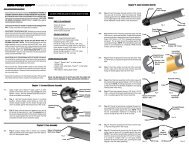
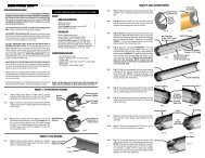
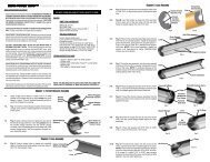
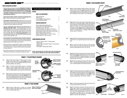
HIGH-POWER RMS Assembly and Operation InstructionsREAD THIS BEFORE YOU BEGIN:• Study the illustrations and sequence of assembly.THE SEQUENCE OF ASSEMBLY ISEXTREMELY IMPORTANT. READ ALL INSTRUCTIONS BEFORE USE. USE RMSMOTORS AND RELOAD KITS ONLY IN ACCORDANCE WITH ALL INSTRUCTIONS.Review the parts list and become familiar with all parts before assembly. IF ANY PARTSARE MISSING OR DAMAGED, CONTACT RCS AT 1-435-865-7100 or email atwarranty@aerotech-rocketry.com.• DO NOT USE ANY PARTS OF THE RMS SYSTEM THAT ARE DAMAGED IN ANYWAY. If in doubt, contact RCS at the number above for assistance.• DO NOT MODIFY THE MOTOR IN ANY WAY. Modification of the motor or the reloadkit parts could result in motor failure, lead to the destruction of both your rocket and motorand may cause personal injury, death and/or property damage. Modification of the motoror reload kit in any way will invalidate your motor warranty.• USE ONLY AEROTECH/RCS RMS RELOAD KITS AND MOTOR PARTS TOREFURBISH YOUR RMS MOTOR. The <strong>AeroTech</strong>/RCS reload kits have beendesigned specifically for use in your particular <strong>AeroTech</strong>/RCS RMS motor. Use ofimitation components may destroy your motor, rocket and payload and will invalidateyour motor warranty. Only use <strong>AeroTech</strong>/RCS RMS reload kits intended for yourspecific <strong>AeroTech</strong>/RCS RMS motor. DO NOT INTERCHANGE PARTS! Do not use<strong>AeroTech</strong>/RCS RMS reload kits or motor components for any other purpose than torefurbish an <strong>AeroTech</strong>/RCS RMS motor.• DO NOT REUSE ANY OF THE DISPOSABLE PARTS OF THE RMS RELOAD KIT.This includes the liner, nozzle and o-rings. These components have been designed forone use only and must be discarded after firing. Reuse can result in motor failure duringsubsequent operation and will invalidate your motor warranty.• Motors are hot after firing. Although the RMS operates at a lower temperature thanmost disposable motors, the higher thermal conductivity of the aluminum motor partsmay make it seem otherwise. If necessary to handle a motor before it has cooled down,use a rag or similar article.DO NOT OPEN RELOAD KIT UNTIL READY TO USE.PARTS:RMS-<strong>75</strong> HARDWARE<strong>75</strong>mm aft closure 1<strong>75</strong>/5120 case 1<strong>75</strong>mm plugged forward closure 1<strong>75</strong>mm forward seal disk 1RELOAD PARTS KITNozzle (large black plastic part) 1Liner (2-3/4" O.D. black plastic tube) 1Propellant grains (7/8” core) 4Fwd & aft o-rings (1/8" thick X 2-3/4" O.D.) 2Forward seal disk o-ring (3/32” thick x 2-9/16” O.D.) 1Grain spacer o-rings (1/16” thick x 2-1/2” O.D.) 3Smoke charge (short solid part) 1Smoke charge insulator (1-1/2" O.D. tube) 1Nozzle Cap (2-1/4” dia. red cap) 1ITEMS NEEDED FOR USE:• Synco Super Lube or other grease• Hobby knife• Electric match w/thermalite, Firestar or other igniter• Masking tape• Wet wipes or damp paper towels2-2. Fig.-4: Insert the larger diameter portion of the nozzleinto one end of the liner, with the nozzle liner flangeseated against the liner. NOTE: RMS-<strong>75</strong>/5120 motorsuse a single large throat nozzle rather than the multiplethroat“Medusa” nozzle shown in the illustrations.2-3. Fig.-5: Perform the remaining assembly steps with theliner held in a horizontal position. Install the propellantgrains into the liner, placing the three (3) grain spacer o-rings (1/16” thick x 2-1/2” O.D.) between each propellantgrain. The aft grain should be seated against thenozzle grain flange. NOTE: Three propellant grains areshown in all illustrations for simplicity. RMS-<strong>75</strong>/5120motors use four (4) grains.2-4. Fig.-6: Place the greased forward seal disk (3/32" thickX 2-9/16" O.D.) o-ring into the groove in the forward sealdisk.2-5. Fig.-7: Insert the smaller (o-ring) end of the seal diskinto the open end of the liner tube until the seal diskflange is seated against the end of the liner.Chapter 2. Case Assembly (Cont’d)LinerNozzleFig.-6NozzleLiner FlangeGrain SpacerO-ringsFig.-4Fig.-5NozzleGrain FlangeGreased ForwardSeal Disk O-ringForward SealDisk (AluminumWasher)LinerLiner(Deburred)PropellantGrains (7/8” Core)Forward SealDisk AssemblyFig.-7• Read and follow the safety code of the Tripoli Rocketry Association (TRA) and complywith all federal, state and local laws in all activities involving high power rockets.1-1. Apply a light coat of Synco Super Lube or othergrease to all threads and all o-rings (except the grainspacer o-rings). This will facilitate assembly and preventsthe threads from seizing.1-2. Fig.-1: Hold the forward (black) closure in a verticalposition, smoke charge cavity facing up. Insert thesmoke charge insulator into the smoke charge cavityuntil it is seated against the forward end of the cavity.1-3. Fig.-2: Apply a liberal amount of grease to one end ofthe smoke charge element. Insert the greased end ofthe smoke charge element into the smoke charge cavityuntil it is seated against the end of the cavity. Set thecompleted forward closure assembly aside.Chapter 1. Forward Closure AssemblySAVE THE RELOAD KIT PLASTIC BAG FOR THE USED RE-LOAD PARTS. DISPOSE OF BAG AND PARTS PROPERLY.SmokeChargeCavitySmoke ChargeElementFig.-2Fig.-1<strong>75</strong>mm Forward(Black) ClosureSmoke ChargeInsulatorGreasedEnd ofSmoke Charge2-6. Fig.-8: Push the liner assembly into the motor case untilthe nozzle protrudes approximately 1-3/4” from the endof the case. NOTE: A coating of grease on the outsidesurface of the liner will facilitate installation and casingcleanup after motor firing.2-6. Fig.-9: Place the greased forward (1/8" thick X 2-3/4"O.D.) o-ring into the forward (bulkhead) end of the caseuntil it is seated against the forward seal disk.2-7. Fig.-10: Thread the previously-completed forward closureassembly into the forward end of the motor case byhand until it is seated against the case. NOTE: Therewill be considerable resistance to threading in theclosure during the last 1/8" to 3/16" of travel.CaseNozzle (ProtrudesAbout 1-3/4”)CaseFig.-8CaseForward O-RingFig.-9ForwardSeal DiskForward ClosureAssemblyFig.-10Chapter 2. Case Assembly2-8. Fig.-11: Place the greased aft (1/8" thick X 2-3/4" O.D.)o-ring into the groove in the nozzle.Case2-1. Fig.-3: Using a hobby knife or similar tool, carefullydeburr (chamfer) both inside edges of the liner tube (2-3/4” O.D. black plastic tube).Deburr (Chamfer)Both inner EdgesFig.-3Liner2-9. Fig.-12: Thread the aft closure into the aft end of themotor case by hand until it is seated against the case.NOTE: There will be considerable resistance to threadingin the closure during the last 1/8" to 3/16" of travel.It is normal if a slight (1/32” to 1/16”) gap remainsbetween the closure and the case, and the grains rattleslightly in the liner after tightening.Fig.-11Aft O-ringAft(Nozzle)End ViewsAft ClosureFig.-12