Initiator Instructions - AeroTech
Initiator Instructions - AeroTech
Initiator Instructions - AeroTech
- No tags were found...

Create successful ePaper yourself
Turn your PDF publications into a flip-book with our unique Google optimized e-Paper software.
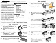
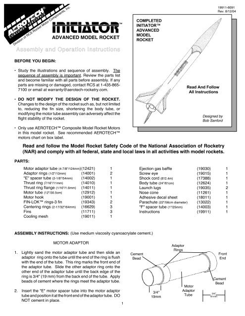
Division of RCS Rocket Motor Components, Inc.Assembly and Operation <strong>Instructions</strong>BEFORE YOU BEGIN:ADVANCED MODEL ROCKETCOMPLETEDINITIATORADVANCEDMODELROCKET19911-8091Rev. 8/12/04• Study the illustrations and sequence of assembly. Thesequence of assembly is important. Review the parts listand become familiar with all parts before assembly. If anyparts are missing or damaged, contact RCS at 1-435-865-7100 or email at warranty@aerotech-rocketry.com.• DO NOT MODIFY THE DESIGN OF THE ROCKET.Changes to the design of the rocket such as, but not limitedto, reducing the fin size, shortening the body tube, ormodifying the motor tube assembly can adversely affect theflight stability of the rocket.• Only use AEROTECH Composite Model Rocket Motorsin this model rocket. See recommended AEROTECHmotors chart on box label.Read And FollowAll <strong>Instructions</strong>Designed byBob SanfordRead and follow the Model Rocket Safety Code of the National Association of Rocketry(NAR) and comply with all federal, state and local laws in all activities with model rockets.PARTS:Motor adaptor tube (4-7/8"/124mm)(12421) 1Adaptor rings (1/2"/13mm) (14001) 2"E" spacer tube (2-1/8"/54mm) (14002) 1Thrust ring (7/16"/11mm) (14010) 1Thrust ring flange (1/16"/1.6mm) (14011) 1Motor tube (12"/30.5cm) (12912) 1Motor hook (19001) 1FIN-LOK rings-3 fin (19343) 2Centering rings (2-17/32"/64mm) (16629) 3Fins (11711) 3Cooling mesh (19011) 1Ejection gas baffle (19030) 1Screw eye (19015) 1Shock cord (8'/2.4m) (17388) 1Body tube (24"/61cm) (12624) 1Launch lugs (19035) 2Nose cone (11261) 1Adhesive decal sheet (18011) 1Parachute (22"/56cm diameter) (13022) 1"F" spacer tube (1"/25mm) (14003) 1<strong>Instructions</strong> (19911) 1ASSEMBLY INSTRUCTIONS: (Use medium viscosity cyanoacrylate cement.)MOTOR ADAPTOR1. Lightly sand the motor adaptor tube and then slide anadaptor ring onto the tube until the end of the ring is flushwith the end of the tube. This ring marks the front end ofthe adaptor tube. Slide the other adaptor ring onto theother end of the adaptor tube until the back edge of thering is 3/4" (19 mm) from the back end of the tube. Applybeads of cement where the rings meet the adaptor tube.2. Insert the "E" motor spacer tube into the motor adaptortube and position it at the front end of the adaptor tube. DONOT cement in place.1CementBead3/4"19mmAdaptorRingsMotorAdaptorTubeCementBead3/4"19 mmFrontEnd
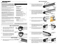
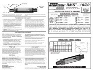
Back Edge OfMotor Tube7/8"22 mmFront Edge OfBack FIN-LOKRing2-15/16"75 mm4-5/8"117 mmBack Edge OfFront FIN-LOKRingMotorHookSlotLOCATIONGUIDE1/4"6 mm1/2"13 mmMOTOR TUBE ASSEMBLYMotorHookFrontEndThrustRingFlangeThrustRingMotorTubeLineSlot ForMotorHook4-5/8"/117mmFrom Back Edge OfMotor TubeFIN-LOKRingLocation Marks7/8"/22mm And 2-15/16"/75mmFrom Back Edge Of Motor Tube1. Cement the thrust ring flange (1/16"/1.6 mm thick) to thethrust ring (7/16"/11 mm long). Set the thrust ring assemblyaside to dry.from the back end of the motor tube. This mark locateswhere the front edge of the rear most FIN-LOK ring willbe.2. Find the line drawn along the side of the motor tube. Usingthe Location Guide printed along the top edge of thisinstruction sheet, cut a 1/4" (6 mm) long slot 4-5/8"(117mm) from the back end of the motor tube and next tothe line on the motor tube as shown.3. Using the Location Guide, make a mark along the motortube line 2-15/16" (75 mm) from the back end of the motortube. This mark locates where the back edge of the frontFIN-LOK ring will be. Make another mark 7/8" (22 mm)FIN-LOKRingFIN-LOK ASSEMBLY4. Insert the tab of the motor hook into the slot cut into themotor tube. Use a small dowel to apply several dropsof cement around the inside of the motor tube justbehind where the motor hook comes through themotor tube wall. Then, with the thrust ring flange facingthe back, insert the thrust ring assembly into the motortube. Use the motor adaptor to push the thrust ringassembly forward until it stops against the tab of the motorhook. Remove the motor adaptor.FrontEndAERO-FIBRECenteringRingMotorTubeMotorHookChannelsNOTE: FROM THIS POINT ON, DO NOT USE ANYCEMENT UNTIL REACHING ASSEMBLY STEP 5.after they are on the motor tube, use a small piece of clothto provide a better grip.)1. With their motor hook channels aligned with the motorhook, slide a FIN-LOK ring and then an AERO-FI-BRE centering ring over the front end of the motortube. Push on the centering ring until the back edge of theFIN-LOK ring is moved to the forward most mark madein Step 3 above. (NOTE: The rings are designed to be atight fit on the motor tube. If the rings are difficult to slideonto the motor tube, round the inside edges of the ringswith sandpaper. If the FIN-LOK rings need to be turned22. Slide the other FIN-LOK ring and then a centering ringover the back end of the motor tube. Push on thecentering ring until the front edge of the FIN-LOK ringis at the rear-most mark made in Step 3.3. Using the line on the motor tube as a guide, gently twist theback centering ring slightly until the fin locks of the backFIN-LOK ring are aligned with the fin locks of the frontFIN-LOK ring.
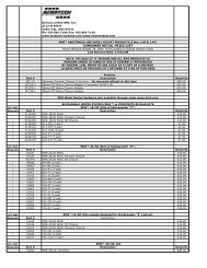
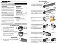
FIN-LOK ASSEMBLY (CONT.)FrontCenteringRingFrontEndCementBeads4. Test the proper positioning and alignment of the FIN-LOK rings by snapping the fins into the fin locks. If anyfin does not snap into place, check to see that each FIN-LOK ring is the correct distance from the back end of themotor tube and that the fin has no plastic flashing left fromproduction that may be preventing a proper fit. Removeany plastic flashing with a hobby knife or sandpaper. Aftermaking any adjustments, carefully remove the fins andthe back centering ring. Check that the front centeringring is still positioned next to and touching the front FIN-LOK ring.5. Apply a bead of cement where the front centering ringmeets the motor tube. Without getting cement into any ofthe finlocks, apply cement only to the areas BETWEENthe finlocks where the front FIN-LOK ring meets theLABYRINTH ASSEMBLYDO NOT ALLOW CEMENTTO GET IN THE FIN LOCKSfront centering ring and the motor tube.6. Without getting cement into any of the fin locks, applycement only to the areas BETWEEN the fin locks whereonly the front edge of the back FIN-LOKring meets themotor tube. DO NOT apply cement to the back edge of theback FIN-LOK ring. (NOTE: The unique AEROTECHFIN-LOK fin mounting system carries and distributesaerodynamic and thrust loads throughout an integratedrocket structure in a manner found in large aerospacevehicles. Loads are primarily borne by structural membersand not cement.)7. Apply a bead of cement around the motor hook forward ofthe front centering ring.DO NOT CEMENT COOLINGMESH INTO MOTOR TUBEMotorTube1/4"/6mmCutsBaffleFlangeShockCordScrewEyePermanentCooling Mesh(Stretch Out - 6")EjectionGas BaffleShoulderCenteringRing1. Make four 1/4" (6mm) long cuts, 90 degrees apart, in thefront end of the motor tube.4. Apply beads of cement where the baffle meets themotor tube and into each of the cuts in the motor tube.2. Stretch out the cooling mesh to about 6" (15cm) in length.Insert the cooling mesh into the front end of the motortube. (NOTE: Do not cement the mesh into the motortube.)3. Apply a thin film of cement to the front 2/3rd's of theshoulder of the ejection gas baffle and insert the baffleshoulder into the front end of the motor tube.35. Apply cement to the front surface of the baffle flange andplace an AERO-FIBRE centering ring over the front endof the baffle so it rests upon the baffle flange.6. Screw the screw eye all the way into the hole at the frontend of the baffle. Securely tie an end of the shock cord tothe screw eye with a square knot. (CAUTION: Do not putcement on the knot of the shock cord. Cement will weakenthe shock cord.)
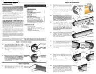
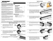
FinBODY AND FIN ASSEMBLYFinRootLaunchLugMotorTubeAssemblyFIN-LOKTabLaunchLugSlotBodyTubeShockCordCementBeadsFinSlot1. Using a hobby knife, carefully remove any body tubematerial that may still be attached to any pre-cut slots inthe body tube.2. Insert the loose end of the shock cord and then the motortube assembly into the back of the rocket body tube asshown. Position the motor tube assembly so that the finlocks are located under and visible through the bodytube's pre-cut fin slots.3. Apply cement along the full length of the fin root of a fin(area of the fin that makes contact with the outside surfaceof the body tube). Carefully insert the fin through a slot inthe body tube and snap the fin into place. Repeat thisFINAL ASSEMBLY AND FINISHINGShroudLineLoopsprocess for the other two fins. (NOTE: Each fin should besnug against the body tube.)4. Through the back end of the body tube, apply cementwhere the fin tabs meet the motor tube, fin locks, frontcentering ring and body tube. Through the front end of thebody tube, apply cement where the baffle assemblycentering ring meets the inside surface of the body tube.5. Lightly sand the surface of the body tube around thelaunch lug slots. Apply cement to the base of a launch lug.With the sloping portion of the launch lug toward the frontof the body tube, insert the tab on the bottom of the lug intoone of the pre-cut launch lug slots in the body tube.Repeat this process for the other launch lug.MoldedLoopCenteringRingShroudLinesNoseConeSelfAdhesiveDecalsShockCordFabricParachuteCanopy1. Slide the remaining centering ring over the back of themotor tube and motor hook and push it against the backFIN-LOK ring. Apply a bead of cement where thecentering ring meets the body tube.2. Paint the rocket body and fins white. (CAUTION: Makesure the paint is compatible with high impact polystyreneplastic.)43. Carefully cut out the self adhesive decals and apply themto the rocket body and fins. Use the picture on page 1 asa guide to proper positioning.4. Paint the nose cone with a shade of red that matches thered of the decals. (CAUTION: Do not paint the portion ofthe nose cone that fits inside the body tube (the shoulder).Paint on the shoulder may cause the nose cone to stickand hinder or prevent parachute ejection.)
5. Securely tie the loose end of the shock cord to the loopmolded into the shoulder of the nose cone with a squareknot. (CAUTION: Do not put cement on the knot of theshock cord. Cement will weaken the shock cord.)6. Fasten the fabric parachute to the shock cord at a pointabout one (1) foot away from the nose cone in thefollowing manner. Stretch out the shroud lines of theparachute so that the lines form three (3) loops one on topof the other. Lay the shock cord across all the shroudlines. Pass the canopy of the parachute over the shockcord and through the three (3) loops made by the shroudlines and pull tight. Pack the parachute and insert thenose cone into the body tube.CUTAWAY VIEW OF COMPLETED INITIATORVEHICLE DATALength: 39"/99 cmDiameter: 2.6"/6.7 cmWeight (Without Motor): 14 oz/400 gmsNose Cone: 5:1 OgiveFins: 3-Swept With "Cranked" LeadingEdgesStages: 1Number Of Motors: 1Recovery System: ParachuteDECAL INSTRUCTIONS1. Handle the decal sheet carefully to avoid damage. Do notcrease the decal sheet.bowl with warm water and put one or two drops of adishwashing detergent into the water.2. Use a pair of sharp scissors or a hobby knife to cut out thedecals.3. Cutting out decals that will be positioned close togetheron the rocket as one block will make them easier to apply.4. Make smooth cuts. Small knicks can cause a decal totear when it is being peeled off the backing sheet.5. Before starting to peel decals off their backings, fill a soup6. Carefully peel a decal off its backing, dip it into thedetergent solution and apply the decal to the rocket. Thedetergent solution prevents the adhesive on the decalfrom "grabbing" the rocket surface too quickly and allowsaccurate positioning of the decal.7. Gently press any air bubbles out from under the decal andthen dab the decal dry.8. Apply the rest of the decals in the same manner.5
OPERATION INSTRUCTIONS1. RECOMMENDED MOTORS: Only use AEROTECH composite modelrocket motors when flying your AEROTECH rocket. See enclosed chartfor recommended motors and projected altitudes.2. RECOVERY SYSTEM PREPARATION: Roll the parachute and shroudlines, starting from the canopy peak, into a loose cylinder that will easilyslide into the lower body assembly body tube. Pack the long portion of theshock cord into the body tube first. Next, insert the parachute. Finally,insert the short length of shock cord into the body tube on top of theparachute and put on the nose cone (or payload bay if your rocket hasone). Make sure that the parachute, shroud lines and shock cord are notcaught between the body tube and the shoulder of the nose cone orpayload bay. The nose cone or payload bay should slide freely. (NOTE:Because your AEROTECH rocket has the LABYRINTH ejection gascooling system, no recovery wadding is required.)3. MOTOR PREPARATION: The motors recommended for your AERO-TECH rocket vary in physical size as well as performance. Your rocketcomes with a changeable motor adaptor and spacer tubes that permit thethe rocket to use each of the recommended motors without permanentmodification to the rocket.Prepare your AEROTECH rocket motor according to the instructions thatcome with the motor. Be sure the motor hook snaps in behind the nozzleend of the motor and holds the motor securely in place. If the motor hookdoes not hold the motor in place, bend the end of the hook until it does.4. PRE-LAUNCH CHECKOUT: Before EVERY flight, perform a completepre-launch checkout of your rocket;• Check that all fins and launch lugs are mounted securely and notdamaged.• Examine the body tube, nose cone and payload bay to make surethey are free of damage.• Check that the shock cord is securely mounted to the ejection gasbaffle and nose cone (or payload bay bulkhead).• Check that the parachute is securely tied to the shock cord.5. LAUNCH PAD: Your AEROTECH rocket must be flown from a launch padwith a 1/4"(6.4mm) diameter metal launch rod at least 36"(0.9m) long (asmeasured from the top of the blast deflector), such as the AEROTECHMANTIS model rocket launch pad.6. MOTOR IGNITION: Only launch your rocket using a remotely controlledand electrically operated launch controller such as the AEROTECH®INTERLOCK model rocket launch controller. Keep yourself and allother people at least 30 feet (10 meters) away from the rocket duringlaunch.7. LAUNCH AREA: Launch the rocket in a cleared outdoor area free of talltrees, power lines and buildings. The side dimensions of the cleared areashould be at least one half of the projected altitude. An area for a radiusof at least 5 feet (1.5 meters) from the launcher should be clear of dry grassor other flammable substances. Read and follow the Model Rocket SafetyCode of the National Association of Rocketry (NAR) and comply with allfederal, state and local laws in all activities with model rockets. A copy ofthe NAR safety code is shown on the instructions that come with allAEROTECH composite model rocket motors.8. FLIGHT PROFILE: When the launch button of the electrical launchcontroller is pressed, an electrical current causes the AEROTECH COP-PERHEAD single lead igniter to ignite the composite propellant of theAEROTECH rocket motor. The motor quickly builds up thrust and powersyour AEROTECH rocket into the air. During powered flight the rocketincreases in speed and altitude. When the propellant burns out the rocketis moving at maximum velocity and a time delay material (delay grain)inside the motor burns. While the delay grain burns the rocket coasts topeak altitude at which point the delay grain ignites the ejection chargewithin the forward part of the motor. The ignition of the ejection chargecreates a burst of hot expanding gas which is cooled by the permanentmetal mesh of the LABYRINTH ejection gas cooling system. Thecooled gas flows around the baffle, pressurizes the parachute bay andejects the nose cone (or payload bay) and parachute. The parachute thendeploys and gently returns the rocket to the ground where the rocket canbe prepared for another flight.9. TRANSPORT AND STORAGE: To avoid damage to your AEROTECHrocket during transport, pack it in a box surrounded by soft packing. Storeyour rocket at room temperature.• Check that the shock cord and parachute are free of any damage.• See that the nose cone (or payload bay), packed parachute andshock cord move freely. After awhile, an ejection charge residuemay build up at the top inside surface of the body tube. Wipe thisresidue away with isopropyl ("rubbing") alcohol.• With the tail of the rocket pointed down and the motor tube empty,shake the rocket to remove any loose ejection charge debris leftfrom a previous flight. Periodically, fluff up the cooling mesh usinga bent wire inserted through the back end of the motor tube.• Be certain the motor to be used is a recommended AEROTECHmodel rocket motor and of a size appropriate for the launch area.• Be sure the motor hook, motor adaptor and motor tube are notdamaged and hold the motor securely in place.If the pre-launch checkout reveals any damage, repair the damagebefore the rocket is flown again.NOTICE: As we cannot control the storage and use of our products, once sold we cannotassume any responsibility for product storage, transportation or usage. RCS shall notbe held responsible for any personal injury or property damage resulting from thehandling, storage or use of our product. The buyer assumes all risks and liabilitiestherefrom and accepts and uses <strong>AeroTech</strong>/RCS products on these conditions.No warranty either expressed or implied is made regarding <strong>AeroTech</strong>/RCS products,except for replacement or repair, at RCS’s option, of those products which are provento be defective in manufacture within one year from the date of original purchase. Forrepair or replacement under this warranty, please contact RCS. Proof of purchase willbe required. Note: Your state may provide additional rights not covered by this warranty.<strong>AeroTech</strong> DivisionRCS Rocket Motor Components, Inc.Cedar City, UT 84720www.aerotech-rocketry.com6Made in U.S.A.©2004 RCS Rocket Motor Components, Inc., All rights reserved.