- Page 1 and 2:
BEARING UNITS HIGHLIGHTS: ULTRA-CLA
- Page 3 and 4:
ntnamericas.com TABLE OF CONTENTS P
- Page 5 and 6:
ntnamericas.com PRODUCTS BY INDUSTR
- Page 7 and 8:
ntnamericas.com PRODUCTS BY INDUSTR
- Page 9 and 10:
ntnamericas.com PRODUCTS BY INDUSTR
- Page 11 and 12:
ntnamericas.com PRODUCTS BY INDUSTR
- Page 13 and 14:
ntnamericas.com PRODUCTS BY INDUSTR
- Page 15 and 16:
ntnamericas.com 6 7 1 2 8 3 4 5 9 1
- Page 17 and 18:
ntnamericas.com NEW INNOVATIONS 4 5
- Page 19 and 20:
ntnamericas.com NEW INNOVATIONS FOO
- Page 21 and 22:
ntnamericas.com ULTRA-CLASS INTROD
- Page 23 and 24:
ntnamericas.com ULTRA-CLASS SERIES
- Page 25 and 26:
ntnamericas.com ULTRA-CLASS SERIES
- Page 27 and 28:
ntnamericas.com ULTRA-CLASS SERIES
- Page 29 and 30:
ntnamericas.com ULTRA-CLASS SERIES
- Page 31 and 32:
ntnamericas.com ULTRA-CLASS SERIES
- Page 33 and 34:
ntnamericas.com ULTRA-CLASS SERIES
- Page 35 and 36:
ntnamericas.com ULTRA-CLASS SERIES
- Page 37 and 38:
ntnamericas.com ULTRA-CLASS SERIES
- Page 39 and 40:
ntnamericas.com ULTRA-CLASS SERIES
- Page 41 and 42:
ntnamericas.com ULTRA-CLASS SERIES
- Page 43 and 44:
ntnamericas.com ULTRA-CLASS SERIES
- Page 45 and 46:
ntnamericas.com ULTRA-CLASS Cat No
- Page 47 and 48:
ntnamericas.com Cat No A-1400V 3/7/
- Page 49 and 50:
ntnamericas.com ULTRA-CLASS BEARING
- Page 51 and 52:
ntnamericas.com STANDARD INTRODUCTI
- Page 53 and 54:
ntnamericas.com STANDARD NOTES 51
- Page 55 and 56:
ntnamericas.com STANDARD SERIES UCP
- Page 57 and 58:
ntnamericas.com STANDARD SERIES UCP
- Page 59 and 60:
ntnamericas.com STANDARD SERIES UCP
- Page 61 and 62:
ntnamericas.com STANDARD SERIES UCH
- Page 63 and 64:
ntnamericas.com STANDARD SERIES ASP
- Page 65 and 66:
ntnamericas.com ASRPP2 Pillow block
- Page 67 and 68:
ntnamericas.com STANDARD SERIES UEL
- Page 69 and 70:
ntnamericas.com STANDARD SERIES UEL
- Page 71 and 72:
UELUP2 j ntnamericas.com Narrow pil
- Page 73 and 74:
ntnamericas.com STANDARD SERIES AEL
- Page 75 and 76:
ntnamericas.com STANDARD SERIES AEL
- Page 77 and 78:
ntnamericas.com STANDARD SERIES UKP
- Page 79 and 80:
ntnamericas.com STANDARD SERIES UCF
- Page 81 and 82:
ntnamericas.com STANDARD SERIES UCF
- Page 83 and 84:
ntnamericas.com UCFLG2 Rhombus flan
- Page 85 and 86:
ntnamericas.com STANDARD SERIES ASP
- Page 87 and 88:
ntnamericas.com STANDARD SERIES UEL
- Page 89 and 90:
ntnamericas.com STANDARD SERIES UEL
- Page 91 and 92:
ntnamericas.com STANDARD SERIES AEL
- Page 93 and 94:
ntnamericas.com STANDARD SERIES AEL
- Page 95 and 96:
ntnamericas.com STANDARD SERIES JEL
- Page 97 and 98:
ntnamericas.com STANDARD SERIES JEL
- Page 99 and 100:
ntnamericas.com STANDARD SERIES UKF
- Page 101 and 102:
ntnamericas.com STANDARD SERIES UKF
- Page 103 and 104:
ntnamericas.com STANDARD SERIES UCF
- Page 105 and 106:
ntnamericas.com STANDARD SERIES UCF
- Page 107 and 108:
ntnamericas.com STANDARD SERIES UCF
- Page 109 and 110:
ntnamericas.com STANDARD NOTES 107
- Page 111 and 112:
ntnamericas.com STANDARD SERIES UCF
- Page 113 and 114:
ntnamericas.com STANDARD SERIES UCF
- Page 115 and 116:
ntnamericas.com STANDARD SERIES UEL
- Page 117 and 118:
ntnamericas.com STANDARD SERIES UEL
- Page 119 and 120:
ntnamericas.com STANDARD NOTES 117
- Page 121 and 122:
ntnamericas.com STANDARD SERIES UCF
- Page 123 and 124:
ntnamericas.com STANDARD SERIES UCF
- Page 125 and 126:
ntnamericas.com STANDARD SERIES UCF
- Page 127 and 128:
ntnamericas.com STANDARD SERIES UCF
- Page 129 and 130:
ntnamericas.com STANDARD SERIES UCH
- Page 131 and 132:
ntnamericas.com AELPF2 Round flange
- Page 133 and 134:
ntnamericas.com STANDARD SERIES UEL
- Page 135 and 136:
ntnamericas.com STANDARD NOTES 133
- Page 137 and 138:
ntnamericas.com STANDARD SERIES UKF
- Page 139 and 140:
ntnamericas.com STANDARD SERIES UCT
- Page 141 and 142:
ntnamericas.com STANDARD SERIES UCT
- Page 143 and 144:
ntnamericas.com UCT3 STANDARD SERIE
- Page 145 and 146:
ntnamericas.com UCT3 STANDARD SERIE
- Page 147 and 148:
ntnamericas.com UCTX UCTX NTN NTN S
- Page 149 and 150:
ntnamericas.com UCTX UCTX NTN NTN S
- Page 151 and 152:
ntnamericas.com STANDARD SERIES UEL
- Page 153 and 154:
ntnamericas.com STANDARD SERIES UEL
- Page 155 and 156:
ntnamericas.com STANDARD SERIES UEL
- Page 157 and 158:
ntnamericas.com STANDARD SERIES UEL
- Page 159 and 160:
ntnamericas.com UKT2 STANDARD SERIE
- Page 161 and 162:
ntnamericas.com UKT2 STANDARD SERIE
- Page 163 and 164:
ntnamericas.com STANDARD SERIES UCM
- Page 165 and 166:
ntnamericas.com STANDARD SERIES AEL
- Page 167 and 168:
ntnamericas.com STANDARD SERIES UCC
- Page 169 and 170:
ntnamericas.com STANDARD SERIES UCC
- Page 171 and 172:
ntnamericas.com STANDARD SERIES UEL
- Page 173 and 174:
ntnamericas.com STANDARD SERIES UEL
- Page 175 and 176:
ntnamericas.com STANDARD SERIES UKC
- Page 177 and 178:
ntnamericas.com STANDARD SERIES UC2
- Page 179 and 180:
ntnamericas.com STANDARD SERIES UC3
- Page 181 and 182:
ntnamericas.com STANDARD SERIES UCX
- Page 183 and 184:
ntnamericas.com STANDARD SERIES AS2
- Page 185 and 186:
ntnamericas.com STANDARD SERIES AR2
- Page 187 and 188:
ntnamericas.com STANDARD SERIES UCS
- Page 189 and 190:
ntnamericas.com STANDARD SERIES UCS
- Page 191 and 192:
ntnamericas.com STANDARD SERIES UEL
- Page 193 and 194:
ntnamericas.com STANDARD NOTES 191
- Page 195 and 196:
ntnamericas.com STANDARD SERIES UEL
- Page 197 and 198:
ntnamericas.com STANDARD SERIES AEL
- Page 199 and 200:
ntnamericas.com STANDARD SERIES REL
- Page 201 and 202:
ntnamericas.com CORROSION-RESISTANT
- Page 203 and 204:
ntnamericas.com INDUSTRY Thermoplas
- Page 205 and 206:
ntnamericas.com CORROSION-RESISTANT
- Page 207 and 208:
ntnamericas.com CORROSION-RESISTANT
- Page 209 and 210:
ntnamericas.com CORROSION-RESISTANT
- Page 211 and 212:
ntnamericas.com CORROSION-RESISTANT
- Page 213 and 214:
ntnamericas.com CORROSION-RESISTANT
- Page 215 and 216:
ntnamericas.com CORROSION-RESISTANT
- Page 217 and 218:
ntnamericas.com CORROSION-RESISTANT
- Page 219 and 220:
ntnamericas.com CORROSION-RESISTANT
- Page 221 and 222:
ntnamericas.com CORROSION-RESISTANT
- Page 223 and 224:
ntnamericas.com CORROSION-RESISTANT
- Page 225 and 226:
ntnamericas.com HEAVY DUTY INTRODUC
- Page 227 and 228:
ntnamericas.com HEAVY DUTY SERIES S
- Page 229 and 230: ntnamericas.com HEAVY DUTY SERIES S
- Page 231 and 232: ntnamericas.com HEAVY DUTY SERIES S
- Page 233 and 234: ntnamericas.com HEAVY DUTY SERIES S
- Page 235 and 236: ntnamericas.com HEAVY DUTY SERIES S
- Page 237 and 238: ntnamericas.com HEAVY DUTY SERIES S
- Page 239 and 240: ntnamericas.com HEAVY DUTY SERIES S
- Page 241 and 242: ntnamericas.com HEAVY DUTY SERIES S
- Page 243 and 244: ntnamericas.com HEAVY DUTY SERIES S
- Page 245 and 246: ntnamericas.com HEAVY DUTY SRB INSE
- Page 247 and 248: ntnamericas.com HEAVY DUTY SRB INSE
- Page 249 and 250: ntnamericas.com AGRICULTURE INTRODU
- Page 251 and 252: ntnamericas.com AGRICULTURE RUBBER
- Page 253 and 254: ntnamericas.com AGRICULTURE DISC BE
- Page 255 and 256: ntnamericas.com ACCESSORIES INTRODU
- Page 257 and 258: ntnamericas.com ACCESSORIES ADAPTER
- Page 259 and 260: ntnamericas.com ACCESSORIES ADAPTER
- Page 261 and 262: ntnamericas.com ACCESSORIES LOCKNUT
- Page 263 and 264: ntnamericas.com ACCESSORIES LOCKNUT
- Page 265 and 266: ØD ØD ØD ØD ØD ØD ntnamericas
- Page 267 and 268: ntnamericas.com ACCESSORIES LUBRICA
- Page 269 and 270: ntnamericas.com ACCESSORIES INSTALL
- Page 271 and 272: ntnamericas.com ACCESSORIES REMOVAL
- Page 273 and 274: ntnamericas.com APPENDICES INTRODUC
- Page 275 and 276: ntnamericas.com APPENDICES LUBRICAT
- Page 277 and 278: ntnamericas.com APPENDICES LUBRICAT
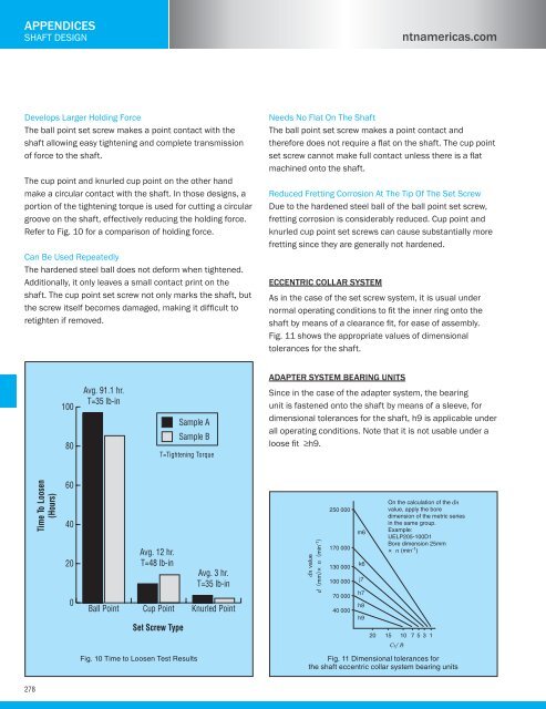
- Page 279: ntnamericas.com APPENDICES SHAFT DE
- Page 283 and 284: ntnamericas.com APPENDICES Technica
- Page 285 and 286: ntnamericas.com APPENDICES INSTALLA
- Page 287 and 288: ntnamericas.com APPENDICES INSTALLA
- Page 289 and 290: ntnamericas.com APPENDICES INSTALLA
- Page 291 and 292: ntnamericas.com APPENDICES INSTALLA
- Page 293 and 294: ntnamericas.com APPENDICES TROUBLES
- Page 295 and 296: ntnamericas.com APPENDICES FAQs Sph
- Page 297 and 298: ntnamericas.com APPENDICES CLEARANC
- Page 299 and 300: ntnamericas.com APPENDICES TOLERANC
- Page 301 and 302: ntnamericas.com 5.2 Tolerances of h
- Page 303 and 304: H H ntnamericas.com APPENDICES TOLE
- Page 305 and 306: ntnamericas.com APPENDICES BALL BEA
- Page 307 and 308: ntnamericas.com APPENDICES ROLLER B
- Page 309 and 310: ntnamericas.com APPENDICES ULTRA-CL
- Page 311 and 312: ntnamericas.com APPENDICES ULTRA-CL
- Page 313 and 314: ntnamericas.com APPENDICES ULTRA-CL
- Page 315 and 316: ntnamericas.com APPENDICES STANDARD
- Page 317 and 318: ntnamericas.com APPENDICES STANDARD
- Page 319 and 320: ntnamericas.com APPENDICES STANDARD
- Page 321 and 322: ntnamericas.com APPENDICES STANDARD
- Page 323 and 324: ntnamericas.com APPENDICES STANDARD
- Page 325 and 326: ntnamericas.com APPENDICES CORROSIO
- Page 327 and 328: ntnamericas.com APPENDICES HEAVY DU
- Page 329 and 330: ntnamericas.com APPENDICES AGRICULT
- Page 331 and 332:
ntnamericas.com APPENDICES INSERT P
- Page 333 and 334:
ntnamericas.com APPENDICES DECIMAL
- Page 335 and 336:
ntnamericas.com APPENDICES PART NUM
- Page 337 and 338:
ntnamericas.com APPENDICES PART NUM
- Page 339 and 340:
ntnamericas.com APPENDICES PART NUM
- Page 341 and 342:
ntnamericas.com APPENDICES PART NUM
- Page 343 and 344:
ntnamericas.com APPENDICES PART NUM
- Page 345 and 346:
ntnamericas.com APPENDICES PART NUM
- Page 347 and 348:
ntnamericas.com APPENDICES PART NUM
- Page 349 and 350:
ntnamericas.com APPENDICES PART NUM
- Page 351 and 352:
ntnamericas.com APPENDICES PART NUM
- Page 353 and 354:
ntnamericas.com APPENDICES PART NUM
- Page 355 and 356:
ntnamericas.com APPENDICES PART NUM
- Page 357 and 358:
ntnamericas.com APPENDICES PART NUM
- Page 359 and 360:
ntnamericas.com APPENDICES PART NUM
- Page 361 and 362:
ntnamericas.com APPENDICES PART NUM
- Page 363 and 364:
ntnamericas.com APPENDICES PART NUM
- Page 365 and 366:
ntnamericas.com APPENDICES PART NUM
- Page 367 and 368:
ntnamericas.com APPENDICES PART NUM
- Page 369 and 370:
ntnamericas.com APPENDICES PART NUM
- Page 371 and 372:
ntnamericas.com APPENDICES PART NUM
- Page 373 and 374:
NTN’s DOL DOL (Distributor On-Lin


