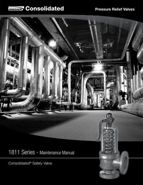
1811 Series - Maintenance Manual
1811 Series - Maintenance Manual
1811 Series - Maintenance Manual

Create successful ePaper yourself
Turn your PDF publications into a flip-book with our unique Google optimized e-Paper software.
<strong>1811</strong> <strong>Series</strong> - <strong>Maintenance</strong> <strong>Manual</strong><br />
Consolidated ® Safety Valve<br />
Pressure Relief Valves
Table of Contents<br />
Section Subject Page No<br />
Conversion Table ...............................................................................................................................3<br />
I. Consolidated Safety Valve Type <strong>1811</strong> ...........................................................................4<br />
II. Product Safety Sign and Label System ........................................................................5<br />
III. Safety Notice ...............................................................................................................6<br />
IV. Safety Precautions .......................................................................................................6<br />
V. Warranty Information ....................................................................................................7<br />
VI. Introduction ..................................................................................................................7<br />
VII. Safety Valve Terminology ..............................................................................................8<br />
VIII. Storage and Handling Prior to Installation .....................................................................9<br />
IX. Recommended Installation Practices<br />
2 | Dresser Consolidated ®<br />
A. General Requirements ...........................................................................................10<br />
B. Outdoor Safety Valve Installation ............................................................................10<br />
X. Hydrostatic Testing & Gagging<br />
A. General Information ...............................................................................................11<br />
B. Application of Test Gags (All Pressures) .................................................................11<br />
XI. Presetting the Adjusting Rings....................................................................................12<br />
XII. Disassembly for Repair ..............................................................................................13<br />
XIII. Inspection<br />
A. General Information ...............................................................................................13<br />
B. Specific Steps .......................................................................................................13<br />
XIV. <strong>Maintenance</strong> Instructions<br />
A. General Information ...............................................................................................18<br />
B. Machining ..............................................................................................................18<br />
C. Lapping Procedures ..............................................................................................19<br />
D. Reconditioning a Ring Lap .....................................................................................19<br />
E. Spindle Runout .....................................................................................................20<br />
F. Spring and Spring Washers ....................................................................................20<br />
XV. Reassembly ...............................................................................................................21<br />
XVI. Steam Testing Procedures .........................................................................................21<br />
XVII. Electronic Valve Testing (EVT) .....................................................................................23<br />
XVIII. Trouble Shooting <strong>1811</strong> Valve ......................................................................................24<br />
XIX. <strong>Maintenance</strong> Tools and Supplies ................................................................................25<br />
XX. Service Parts Inventory Philosophy .............................................................................25<br />
XXI. Recommended Spare Parts .......................................................................................26<br />
XXII. Retrofit - THERMOFLEX Disc .................................................................................27<br />
XXIII. Identification and Ordering Essentials .........................................................................27<br />
XXIV. Manufacturer’s Field Service and Repair Program<br />
A. Factory Setting vs. Field Setting .............................................................................28<br />
B. Field Service ..........................................................................................................28<br />
C. Factory Repair Facilities .........................................................................................28<br />
XXV. Safety Valve <strong>Maintenance</strong> Training ..............................................................................29<br />
XXVI. Genuine Dresser Parts ...............................................................................................29<br />
Sales Office Locations .....................................................................................................................30
Conversion Table<br />
All the USCS values are converted to<br />
Metric values using the following conversion factors:<br />
USCS Unit Conversion Factor Metric Unit<br />
in. 25.4 mm<br />
lb. 0.4535924 kg<br />
in 2 6.4516 cm 2<br />
ft 3 /min 0.2831685 m 3 /min<br />
gal/min 3.785412 L/min<br />
lb/hr 0.4535924 kg/hr<br />
psig 0.6894757 barg<br />
ft lb 1.3558181 Nm<br />
°F 5/9 (°F-32) °C<br />
<strong>1811</strong> <strong>Series</strong> Safety Valve (July/2010) | 3
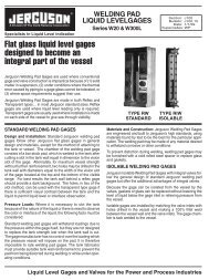
I. Consolidated Safety Valve Type <strong>1811</strong><br />
Part<br />
No.<br />
1 Base<br />
2 Seat Bushing<br />
3 Disc<br />
23<br />
22<br />
4 | Dresser Consolidated ®<br />
Nomenclature<br />
4 Lower Adjusting Ring<br />
5 Lower Adjusting Ring Pin<br />
6 Upper Adjusting Ring<br />
7 Upper Adjusting Ring Pin<br />
8 Yoke<br />
9 Base Stud<br />
10 Stud Nut<br />
11 Spindle<br />
12 Bottom Spring Washer<br />
13 Spring<br />
14 Top Spring Washer<br />
15 Compression Screw<br />
16<br />
Compression Screw<br />
Locknut<br />
17 Cap<br />
18 Cap Set Screw<br />
19 Lever<br />
20 Release Nut<br />
21 Lever Pin<br />
22 Top Lever (4” & 6” Sizes)<br />
23 Drop Lever (4” & 6” Sizes)<br />
24 Release Locknut<br />
Figure: Cap and Lifting Lever<br />
Assembly for 4” and 6” Sizes<br />
17<br />
24<br />
20<br />
19<br />
12<br />
9<br />
10<br />
6<br />
3<br />
7<br />
5<br />
4<br />
1/2”-14 NPT<br />
Drain<br />
2<br />
1<br />
21<br />
16<br />
18<br />
15<br />
14<br />
8<br />
11<br />
13<br />
Figure: <strong>1811</strong> Consolidated Safety Valve<br />
Figure 3: Flat Solid Disc<br />
(Optional)<br />
Figure 4: THERMO<br />
LIP Disc
II. Product Safety Sign and Label System<br />
If and when required, appropriate safety labels have been included in the<br />
rectangular margin blocks throughout this manual. Safety labels are vertically<br />
oriented rectangles as shown in the representative examples (below),<br />
consisting of three panels encircled by a narrow border. The panels can<br />
contain four messages which communicate:<br />
• The level of hazard seriousness<br />
• The nature of the hazard<br />
• The consequence of human, or product, interaction with the hazard.<br />
• The instructions, if necessary, on how to avoid the hazard.<br />
The top panel of the format contains a signal word (DANGER, WARNING,<br />
CAUTION or ATTENTION) which communicates the level of hazard seriousness.<br />
The center panel contains a pictorial which communicates the nature of the<br />
hazard, and the possible consequence of human or product interaction with the<br />
hazard. In some instances of human hazards the pictorial may, instead, depict<br />
what preventive measures to take, such as wearing protective equipment.<br />
The bottom panel may contain an instruction message on how to avoid the<br />
hazard. In the case of human hazard, this message may also contain a more<br />
precise definition of the hazard, and the consequences of human interaction<br />
with the hazard, than can be communicated solely by the pictorial.<br />
1 2 3 4<br />
Do not remove bolts if<br />
pressure in line, as this will<br />
result in severe personal<br />
injury or death.<br />
Know all valve exhaust/<br />
leakage points to avoid<br />
possible severe personal<br />
injury or death.<br />
Wear necessary protective<br />
equipment to prevent<br />
possible injury<br />
1<br />
DANGER — Immediate hazards<br />
which WILL result in severe<br />
personal injury or death.<br />
2<br />
WARNING — Hazards or unsafe<br />
practices which COULD result in<br />
severe personal injury or death.<br />
3<br />
CAUTION — Hazards or unsafe<br />
practices which COULD result in<br />
minor personal injury.<br />
4<br />
ATTENTION — Hazards or<br />
unsafe practices which COULD<br />
result in product or property<br />
damage<br />
Handle valve carefully. Do<br />
not drop or strike.<br />
<strong>1811</strong> <strong>Series</strong> Safety Valve (July/2010) | 5
Wear necessary<br />
protective equipment to<br />
prevent possible injury<br />
Lower pressure and stand<br />
clear of discharge when<br />
working on valve to avoid<br />
severepersonal injury or death.<br />
6 | Dresser Consolidated ®<br />
III. Safety Notice<br />
Proper installation and start-up is essential to the safe and reliable operation of all<br />
valve products. The relevant procedures recommended by Dresser Consolidated ® ,<br />
and described in these instructions, are effective methods of performing the required<br />
tasks.<br />
It is important to note that these instructions contain various “safety messages”<br />
which should be carefully read in order to minimize the risk of personal injury, or the<br />
possibility that improper procedures will be followed which may damage the involved<br />
Dresser Consolidated ® product, or render it unsafe. It is also important to understand<br />
that these “safety messages” are not exhaustive. Dresser Consolidated ® can not<br />
possibly know, evaluate, and advise any customer of all of the conceivable ways<br />
in which tasks might be performed, or of the possible hazardous consequences<br />
of each way. Consequently, Dresser Consolidated ® has not undertaken any such<br />
broad evaluation and, thus, anyone who uses a procedure and/or tool, which is not<br />
recommended by Dresser Consolidated ® , or deviates from Dresser Consolidated ®<br />
recommendations, must be thoroughly satisfied that neither personal safety,<br />
nor valve safety, will be jeopardized by the method and/or tools selected. If not<br />
so satisfied, contact Dresser Consolidated ® (at 318/640-6055) if there are any<br />
questions relative to tools/methods.<br />
The installation and start-up of valves and/or valve products may involve proximity<br />
to fluids at extremely high pressure and/or temperature. Consequently, every<br />
precaution should be taken to prevent injury to personnel during the performance<br />
of any procedure. These precautions should consist of, but are not limited to, ear<br />
drum protection, eye protection, and the use of protective clothing, (i.e., gloves,<br />
etc.) when personnel are in, or around, a valve work area. Due to the various<br />
circumstances and conditions in which these operations may be performed on<br />
Dresser Consolidated ® products, and the possible hazardous consequences of<br />
each way, Dresser Consolidated ® can not possibly evaluate all conditions that<br />
might injure personnel or equipment. Nevertheless, Dresser Consolidated ® does<br />
offer certain Safety Precautions, listed in Section IV, for customer information only.<br />
It is the responsibility of the purchaser or user of Dresser Consolidated ® valves/<br />
equipment to adequately train all personnel who will be working with the involved<br />
valves/equipment. For more information on training schedules, call 318/640-6054.<br />
Further, prior to working with the involved valves/equipment, personnel who are to<br />
perform such work should become thoroughly familiar with the contents of these<br />
instructions. Additional copies of these instructions can be purchased, at a minimal<br />
cost, by contacting Dresser Consolidated ® (in writing) at P.O. Box 1430, Alexandria,<br />
LA 71309-1430, or by calling at 318/ 640-2250, Fax (318) 640-6325.<br />
IV. Safety Precautions<br />
Follow all plant safety regulations, but be sure to observe the following:<br />
• Always lower the working pressure before making any valve adjustment. When<br />
making ring adjustments, always gag the valve before making the adjustment.<br />
This will avoid possible personal injury.<br />
• Do not stand in front of the discharge side of a safety valve when testing or<br />
operating.<br />
• Hearing and eye protection should be used when testing or operating a valve.<br />
• Wear protective clothing. Hot water can burn and superheated steam is not<br />
visible.
IV. (Contd.)<br />
• When removing the safety valve during disassembly, stand clear and/or wear<br />
protective clothing to prevent exposure to splatter, or any corrosive process<br />
medium, which may have been trapped inside the valve. Ensure the valve is<br />
isolated from system pressure before the valve is removed.<br />
• Exercise care when examining a safety valve for leakage.<br />
• Prior to each actuation, assure that no personnel are near the valve. Steam<br />
escaping from the valve during actuation can possibly cause personal injury.<br />
• When popping a safety valve for the first time, or after refurbishment, always be<br />
prepared to actuate the valve with the lever while standing in a safe place away<br />
from the valve. This may be done by fixing a rope to the lever for actuating the<br />
valve from a distance.<br />
• Striking a valve which is under pressure can cause premature actuation. Never<br />
tamper with the valve when system pressure is near the valve set pressure.<br />
• Before performing any machining on valve parts, consult Dresser Consolidated ®<br />
or its authorized representative. Deviation from critical dimensions can adversely<br />
affect valve performance.<br />
V. Warranty Information<br />
Warranty Statement - Dresser warrants that its products<br />
and work will meet all applicable specifications and other<br />
specific product and work requirements (including those<br />
of performance), if any, and will be free from defects in<br />
material and workmanship. Refer to Dresser’s Standard<br />
Terms of Sale, or specific contract for complete details on<br />
warranty and limitation of remedy and liability.<br />
Defective and nonconforming items must be held for<br />
Dresser’s inspection and returned to the original F.O.B.<br />
point upon request.<br />
Incorrect Selection or Misapplication of Products<br />
- Dresser Consolidated ® cannot be responsible for<br />
customer’s incorrect selection or misapplication of<br />
our products.<br />
VI. Introduction<br />
The “safety valve” is the final safeguard between a<br />
controlled boiler and a catastrophic explosion. In an overpressure<br />
situation, the pressure in the valve inlet increases<br />
until the force on the disc exerted by the system pressure<br />
equals the force exerted by the spring. This causes the<br />
safety valve to pop, or lift, relieving the excess steam until<br />
the system pressure is reduced to the desired level.<br />
The Consolidated Safety Valve has been a leader in<br />
the industry since 1879, thus offering over a century<br />
of experience in design, engineering and product<br />
Know all valve exhaust/<br />
leakage points to avoid<br />
possible severe personal<br />
injury or death.<br />
Unauthorized Repair Work - Dresser Consolidated ®<br />
has not authorized any non-Dresser affiliated repair<br />
companies, contractors or individuals to perform warranty<br />
repair service on new products or field repaired products<br />
of its manufacture. Therefore, customers contracting<br />
such repair services from unauthorized sources must do<br />
so at their own risk.<br />
Unauthorized Removal of Seals - All new valves and<br />
valves repaired in the field by Dresser Field Service are<br />
sealed to assure the customer of our guarantee against<br />
defective workmanship. Unauthorized removal and/or<br />
breakage of this seal will negate our warranty.<br />
manufacture. Dresser’s history of dependable and reliable<br />
valve service assures that today’s products and designs<br />
are consistent with industry’s current requirements.<br />
Rigid manufacturing standards controlled by an ASME<br />
approved Quality Control Program insure that each valve<br />
will be manufactured in accordance with established<br />
design criteria and tested for functional performance.<br />
This quality controlled manufacturing and test program<br />
assures that each valve manufactured will provide long<br />
and reliable service.<br />
<strong>1811</strong> <strong>Series</strong> Safety Valve (July/2010) | 7
VII. Terminology for Safety Valves<br />
(Paraphrased from ASME’s PTC 25)<br />
• Back Pressure<br />
Back pressure is the static pressure existing at the<br />
outlet of a safety valve device due to pressure in the<br />
discharge system.<br />
• Blowdown<br />
Blowdown is the difference between actual popping<br />
pressure of a safety valve and actual reseating<br />
pressure expressed as a percentage of set pressure,<br />
or in pressure units.<br />
• Bore Area<br />
Bore area is the minimum cross-sectional area of the<br />
seat bushing.<br />
• Bore Diameter<br />
Bore diameter is the minimum diameter of the seat<br />
bushing.<br />
• Built-Up Back Pressure<br />
Pressure existing at the outlet of a safety valve while it<br />
is open and flowing through a discharge system.<br />
• Chatter<br />
Chatter is abnormal, rapid reciprocating motion of the<br />
moveable parts of a safety valve, in which the disc<br />
contacts the seat.<br />
• Closing Pressure<br />
Closing pressure is the value of decreasing inlet<br />
static pressure at which the valve disc re-establishes<br />
contact with the seat, or at which lift becomes zero.<br />
• Disc<br />
A disc is the pressure containing moveable member<br />
of a safety valve which effects closure.<br />
• Inlet Size<br />
Inlet size is the nominal pipe size of the inlet of a safety<br />
valve, unless otherwise designated.<br />
• Leak Test Pressure<br />
Leak test pressure is the specified inlet static pressure<br />
at which a quantitative seat leakage test is performed<br />
in accordance with a standard procedure.<br />
• Lift<br />
Lift is the actual travel of the disc away from closed<br />
position when a valve is relieving.<br />
8 | Dresser Consolidated ®<br />
• Lifting Device<br />
A lifting device is a device for manually opening a<br />
safety valve, by the application of external force to<br />
lessen the spring loading which holds the valve<br />
closed.<br />
• Seat Bushing<br />
A seat bushing is the pressure containing element<br />
which constitutes the inlet flow passage and includes<br />
the fixed portion of the seat closure.<br />
• Outlet Size<br />
Outlet size is the nominal pipe size of the outlet passage<br />
of a safety valve, unless otherwise designated.<br />
• Overpressure<br />
Overpressure is a pressure increase over the set<br />
pressure of a safety valve, usually expressed as a<br />
percentage of set pressure.<br />
• Popping Pressure<br />
Popping pressure is the value of increasing inlet<br />
static pressure at which the disc moves in the<br />
opening direction at a faster rate as compared<br />
with corresponding movement at higher or lower<br />
pressures. It applies only to safety or safety relief<br />
valves on compressible fluid service.<br />
• Pressure Containing Member<br />
A pressure containing member of a safety valve is<br />
a part which is in actual contact with the pressure<br />
media in the protected vessel.<br />
• Pressure Retaining Member<br />
A pressure retaining member of a safety valve is a part<br />
which is stressed due to its function in holding one or<br />
more pressure containing members in position.<br />
• Rated Lift<br />
Rated lift is the design lift at which a valve attains its<br />
rated relieving capacity.<br />
• Safety Valve<br />
A safety valve is a pressure relief valve actuated<br />
by inlet static pressure and characterized by rapid<br />
opening or pop action.
VII. (Continued)<br />
• Set Pressure<br />
Set pressure is the value of increasing inlet static<br />
pressure at which a safety valve displays the<br />
operational characteristics as defined under “Popping<br />
Pressure.” It is one value of pressure stamped on the<br />
safety valve.<br />
• Seat<br />
A seat is the pressure containing contact between the<br />
fixed and moving portions of the pressure containing<br />
elements of a valve.<br />
• Seat Diameter<br />
Seat diameter is the smallest diameter of contact<br />
between the fixed and moving members of the<br />
pressure containing elements of a valve.<br />
• Seat Tightness Pressure<br />
Seat tightness pressure is the specific inlet static<br />
pressure at which a quantitative seat leakage test is<br />
performed in accordance with a standard procedure.<br />
• Simmer<br />
Simmer is the audible or visible escape of fluid<br />
between the seat and disc at an inlet static pressure<br />
below the popping pressure and at no measurable<br />
capacity. It applies to safety valves on compressible<br />
fluid service.<br />
• Warn<br />
See “Simmer” (definition above).<br />
VIII. Storage and Handling Prior to Installation<br />
Safety valves should be stored in a dry environment<br />
to protect them from the weather. They should not be<br />
removed from the skids or crates until immediately prior<br />
to installation. Flange protectors and sealing plugs should<br />
remain installed until just prior to installation.<br />
Safety valves, either crated or uncrated, should never<br />
be subjected to sharp impact. This would be most<br />
likely to occur by bumping or dropping during loading<br />
or unloading from a truck or while moving with a power<br />
conveyor, such as a fork lift truck. The valve, either crated<br />
or uncrated, should always be kept with the inlet down<br />
(i.e., never laid on its side), to prevent misalignment and<br />
damage to internals. Even crated valves should always<br />
be lifted with the inlet down.<br />
Do not lift valve horizontally,<br />
or hook to lifting lever or<br />
spring.<br />
Prevent dirt from entering<br />
valve outlet port.<br />
Uncrated valves should be moved or hoisted by wrapping<br />
a chain or sling, around the discharge neck, then around<br />
the upper yoke structure, in such manner as will insure<br />
that the valve is in vertical position during lift, (i.e., not<br />
lifted in horizontal position). Never lift the full weight of<br />
the valve by the lifting lever. Never hook to the spring<br />
to lift. When safety valves are uncrated and the flange<br />
protectors removed, immediately prior to installation,<br />
meticulous care should be exercised to prevent dirt from<br />
entering the outlet port while bolting in place.<br />
While hoisting to the installation, care should be exercised<br />
to prevent bumping the valve against steel structures and<br />
other objects.<br />
Handle valve carefully. Do<br />
not drop or strike.<br />
<strong>1811</strong> <strong>Series</strong> Safety Valve (July/2010) | 9
IX. Recommended Installation Practices<br />
A. General Requirements<br />
The safety valve shall be connected to the boiler in a vertical position independent<br />
of any other steam connection, and attached as close as possible to the boiler.<br />
Intervening pipe or fittings shall be no longer than the face-to-face dimension of the<br />
corresponding tee fitting of the same diameter and pressure under the corresponding<br />
American Standard as set forth by the ASME.<br />
Thoroughly clean the inlet of the valve before installation and be sure that the proper<br />
gasket is used. Tighten bolts evenly. Care should be taken when fastening bolts on<br />
cast iron flanges as cracking may result.<br />
The valve shall be free from external stresses transmitted from the discharge piping.<br />
Figure 5 illustrates a recommended design allowing for ample clearance to take<br />
care of thermal expansion. The riser pipe should be large enough to accommodate<br />
the full capacity of the valve without causing steam to escape by flowing backward<br />
through the drip pan. In no case should the pipe connected to the valve be of a<br />
smaller size than the valve outlet.<br />
Riser supported overhead<br />
Drain Pipe Open<br />
To Safe Place<br />
When a safety valve is installed on an outdoor unit, it is<br />
advisable to insulate the valve body, including the inlet<br />
flange, up to the bottom of the yoke. The insulation will<br />
stabilize the valve body temperature preventing variation<br />
in the set pressure.<br />
10 | Dresser Consolidated ®<br />
3/4” std. pipe &<br />
fittings<br />
Make short as possible<br />
Figure 5: Recommended Installation for Discharge and Vent Piping<br />
B. Outdoor Safety Valve Installation<br />
Know all valve exhaust/<br />
leakage points to avoid<br />
possible severe personal<br />
injury or death.<br />
1/2” - NPT Drain Pipe Open to<br />
Safe Place (Valves manufactured<br />
prior to 1987 may have other<br />
size drain holes)<br />
Valves must be readjusted if insulation is installed.<br />
Weather shielding should be used to protect the spring<br />
and to minimize rain or snow from entering the valve body.
X. Hydrostatic Testing & Gagging<br />
A. General Information<br />
During any hydrostatic test all safety valves on the unit must be gagged. This<br />
gagging procedure prevents the possibility of damage to the safety valve internals<br />
in the event that the test pressure exceeds the safety valve set pressure.<br />
When hydrostatic pressure will exceed the set pressure of the safety valve, it is<br />
recommended the valve be replaced with a blind flange during hydrostatic testing.<br />
Probably the most common source of safety valve trouble is overgagging. During<br />
hydrostatic testing, and during safety valve setting, gags should be applied only<br />
hand tight. During setting, overgagging could cause damage to the seating surface<br />
and result in leakage. In applying gags, remember that the valve spring will hold the<br />
valve closed against its set pressure. The additional gag load applied should be only<br />
enough to insure that the valves do not lift at the expected over-pressure.<br />
Gags should never be applied when the boiler is cold. The spindle of the safety valve<br />
expands considerably with the temperature increase as pressure is raised. If it is not<br />
free to expand with this temperature change, the spindle may be damaged.<br />
Boiler pressure should be increased to 80% of the pressure of the low set valve<br />
before applying the gags.<br />
Hand tighten the gags of drum and superheater valves with only a light force.<br />
B. Application of Test Gags (All Pressures)<br />
1. Refer to Figures 1 & 2 on Section V. Remove lever pin and lever. Then loosen<br />
cap screw and remove cap.<br />
2. Center the test gag screw in the exposed end of the spindle and hook the legs<br />
of gag under the sides of the yoke as shown in Figure 6.<br />
Do not apply the gag load until the boiler hydrostatic pressure is equal<br />
to 80% of the pressure to which the low set valve is adjusted.<br />
3. Apply the gag load by turning the gag screw clockwise. If the gag on any valve<br />
has not been tightened sufficiently, the valve will leak.<br />
If this occurs, the hydrostatic test pressure should be reduced until the<br />
valve becomes tight and then the gag should be tightened still further.<br />
This procedure must be followed exactly since it is very difficult to stop the leak<br />
by additional gagging once it has started. Any attempt to pinch off the leakage<br />
through the valve without first lowering the hydrostatic pressure may result in<br />
damage to the valve seats.<br />
4. After the hydrostatic test is completed, the gags should be removed when the<br />
hydrostatic pressure has been reduced to 85% to 90% of the low set valve.<br />
Under no circumstances should the gags be left on valves with no<br />
hydrostatic pressure on the system.<br />
Gag safety valve during<br />
ring adjustments to avoid<br />
possible severe personal<br />
injury or death.<br />
Figure 6<br />
<strong>1811</strong> <strong>Series</strong> Safety Valve (July/2010) | 11
XI. Presetting the Adjusting Rings<br />
If the correct position of the adjusting rings (as measured<br />
in the disassembly procedure (see Section XII) is not<br />
known, the valve adjusting rings may be positioned using<br />
the information in Table 1.<br />
The lower ring may be positioned by turning the lower<br />
adjusting ring up until it contacts the disc. After choosing<br />
the appropriate orifice size, turn the adjusting ring down<br />
the corresponding number of notches listed in the “Lower<br />
Ring” column. Then, replace the adjusting ring pin. The<br />
adjusting ring must be free to move both directions, but<br />
not rotate.<br />
The upper ring may be positioned by turning the upper<br />
12 | Dresser Consolidated ®<br />
Adjusting Ring Settings<br />
adjusting ring down towards the nozzle bushing, until<br />
it becomes level with the bottom of disk. Then after<br />
choosing the appropriate orifice size, turn the adjusting<br />
ring down the corresponding number of turns (360°) listed<br />
in the “Upper Ring” column. Then replace the adjusting<br />
ring pin. The adjusting ring must be free to move both<br />
directions, but not rotate.<br />
The adjusting rings are now in a starting position for full lift<br />
steam testing. These adjusting ring settings will generally<br />
provide a blowdown greater than required by Section I<br />
of the ASME Code, and should be adjusted for the<br />
particular application.<br />
NOTE: It is important to note that all adjustments of adjusting rings are Dresser Consolidated ® initial adjustments<br />
only, and are not intended to be final adjustments. This final adjustment must be made on the operating system with<br />
conditions approximating those that will be realized under actual operating conditions.<br />
Orifice<br />
Upper Ring<br />
No. of<br />
Notches<br />
Lower Ring<br />
No. of<br />
Notches<br />
Table 1: Adjusting Ring Settings<br />
Upper Ring Position From Being<br />
Level with Bottom of the Disc (Note 1)<br />
Lower Ring Position From Disc<br />
Contact (Note 2)<br />
F 30 26 Down Two Turns Down 4 to 6 Notches<br />
G 30 30 Down Two Turns Down 4 to 6 Notches<br />
H 30 24 Down Two Turns Down 5 to 8 Notches<br />
J 36 30 Down Two Turns Down 5 to 8 Notches<br />
K 45 32 Down Two Turns Down 6 to 10 Notches<br />
L 54 40 Down Two Turns Down 6 to 15 Notches<br />
M 45 36 Down Two Turns Down 6 to 15 Notches<br />
N 50 40 Down Two Turns Down 6 to 15 Notches<br />
P 50 42 Down Two Turns Down 8 to 15 Notches<br />
Q 60 48 Down Two Turns Down 8 to 15 Notches<br />
Note 1: After final set pressure adjustment, set and pin the upper ring to the above specification.<br />
Note 2: These specifications are approximate starting positions. Adjust ring until “good” pop is achieved. Lock<br />
ring and record this position on test report.
XII. Disassembly for Repair<br />
Before removing the valve, be sure there is no steam pressure in the drum or header,<br />
then proceed as follows:<br />
1. Remove lower ring pin.<br />
2. Turn the lower ring upwards counting the number of notches moved until contact<br />
is made with the disc. Record this information for use during reassembly.<br />
3. Remove the lever pin and lever.<br />
4. Loosen the cap screw(s) and remove the cap.<br />
5. Remove the release nut and lock nut or cotter pin.<br />
6. Measure the distance from the top of the spindle to the top of the compression<br />
screw. Record this for use in reassembly to restore the correct spring<br />
compression.<br />
7. Loosen the compression screw lock nut and remove the compression screw.<br />
8. Remove the cap screws or stud nuts holding the yoke to the base and raise the<br />
yoke over the spindle.<br />
9. Remove the spring and spring washer assembly, record the spring number<br />
stamped in the spring. Mark the spring and washers top and bottom.<br />
10. Lift the disc and spindle straight up to remove the disc from the valve body.<br />
Engage the drop through threads of the disc and unscrew it from the spindle.<br />
11. Measure from the top of the combination guide and upper ring to the top of the<br />
bushing seat. Record this measurement for reassembly.<br />
12. Remove the upper ring pin.<br />
13. Remove the combination guide and upper ring by turning it upwards until the<br />
threads disengage.<br />
14. Remove the lower adjusting ring. The valve is now completely disassembled.<br />
XIII. Inspection<br />
A. General Information<br />
Once the valve is disassembled, the appropriate parts can be inspected for damage<br />
and their suitability for reuse.<br />
B. Specific Steps<br />
1. Inspect the guide inside diameter for egging, and insure the inside surface is<br />
smooth. The threads on the outside must be in good condition to insure the<br />
adjusting ring/guide will adjust when the valve is hot. If serious, large scale<br />
galling or ridges corresponding to the grooves in the disc are present, the part<br />
should be replaced.<br />
2. Disc :<br />
The Flat Solid Disc (FSD) and the Thermoflex Disc (TFD). Each of these disc<br />
designs is available in either a low pressure (LP) or high pressure (HP) version.<br />
Do not disassemble valve<br />
with pressure in drum or<br />
header, as this will result<br />
in severe personal injury or<br />
death.<br />
Table 2<br />
Disc<br />
<strong>1811</strong><br />
FSD TFD<br />
(LP) (HP) (LP) (HP)<br />
<strong>1811</strong> <strong>Series</strong> Safety Valve (July/2010) | 13
XIII.B. Continued<br />
<strong>1811</strong>-HP Flat Solid Disc Machining Dimensions<br />
G<br />
14 | Dresser Consolidated ®<br />
A<br />
Figure 8: HP Thermo Lip Disc<br />
L<br />
G<br />
Figure 7: HP Flat Solid Disc<br />
Table 3a: Flat Seat Disc Replacement Criteria (Note 1)<br />
Orifice<br />
in.<br />
H min<br />
mm in.<br />
J min<br />
mm<br />
F 1.640 41.66 .339 8.61<br />
G 1.578 40.08 .339 8.61<br />
H 1.640 41.66 .437 11.10<br />
J 1.609 40.87 .433 11.00<br />
K 1.890 48.01 .506 12.85<br />
L 2.297 58.34 .528 13.41<br />
M 2.422 61.52 .621 15.77<br />
N 2.985 75.82 .684 17.37<br />
P 3.367 85.52 .816 20.73<br />
Q 3.985 101.22 .903 22.94<br />
Note 1: Once a minimum dimension is met, disc is to be<br />
discarded.<br />
<strong>1811</strong>-HP Thermo Lip Disc Machining Dimensions<br />
F<br />
J<br />
F<br />
Q .033 0.84<br />
Note 1: Once a minimum dimension is met, disc is to be<br />
discarded.<br />
H<br />
Table 3b: Flat Seat Disc Rework/Inspection<br />
Dimensions<br />
Orifice<br />
F +.002/-.003 in.<br />
(+0.05/-0.08 mm)<br />
G<br />
in. mm in. mm<br />
F .028 0.71 .062 ± .007 1.57 ± 0.18<br />
G .028 0.71 .062 ± .007 1.57 ± 0.18<br />
H .028 0.71 .062 ± .007 1.57 ± 0.18<br />
J .028 0.71 .062 ± .005 1.57 ± 0.13<br />
K .028 0.71 .062 ± .007 1.57 ± 0.18<br />
L .028 0.71 .062 ± .007 1.57 ± 0.18<br />
M .028 0.71 .062 ± .007 1.57 ± 0.18<br />
N .028 0.71 .062 ± .007 1.57 ± 0.18<br />
P .039 0.99 .078 ± .007 1.98 ± 0.18<br />
Q .039 0.99 .105 ± .005 2.67 ± 0.13<br />
Table 4: Thermo Lip Disc Replacement Criteria (Note 1)<br />
Orifice<br />
in.<br />
F min<br />
mm<br />
F .023 0.58<br />
G .023 0.58<br />
H .023 0.58<br />
J .023 0.58<br />
K .023 0.58<br />
L .023 0.58<br />
M .023 0.58<br />
N .023 0.58<br />
P .033 0.84
XIII.B. Continued<br />
<strong>1811</strong>-HP Thermo Lip Disc Machining Dimensions (Contd.)<br />
The <strong>1811</strong>-HP & LP Thermoflex Discs are designed for<br />
steam service, and are standard on all new <strong>1811</strong> Safety<br />
Valves. The THERMOFLEX Disc prevents most seat<br />
damage by maintaining a tight seal at higher operating<br />
pressures than the Flat Solid Disc. Inspect the disc seat<br />
for steam cuts, nicks, or other damage. If minor damage<br />
has occurred, the seat may be restored by lightly lapping<br />
seat area G, as indicated in Figures 7 & 8. Do not<br />
machine Thermoflex Discs. If dimension F is reduced<br />
to the minimum indicated in Table 4, the disc should<br />
be replaced. Other replacement criteria include thread<br />
damage, spindle bearing surface damage and severe<br />
galling. Egging caused by vibration and wear also require<br />
replacement to maintain “like new” valve performance.<br />
Note 1: Due to the thin seat lip, Thermoflex Discs can not be machined. Damage, if present, may be removed<br />
by lapping unit “F” (min.) is exceeded. The Thermoflex Disc requires replacement when the “F” (min.)<br />
dimension is exceeded<br />
If you find flexible seating configurations different from those shown in Figures 7 & 9, replacement with the<br />
current, improved design Thermoflex Disc is recommended.<br />
<strong>1811</strong>-LP Flat & Thermo Lip Disc Machining Dimensions<br />
Orifice<br />
D<br />
C<br />
45 0<br />
N<br />
15 0<br />
Figure 9: LP Flat Solid & Thermo Lip Discs<br />
Table 5: Low Pressure Disc Rework Inspection Dimensions (Note 1)<br />
C Flat Seat D Thermo Disc D N<br />
in. mm in. mm in. mm in. mm<br />
F - - .834 ± .002 21.18 ± 0.05 .860 ± .002 21.84 ± 0.05 - -<br />
G - - 1.076 ± .002 27.33 ± 0.05 1.092 ± .002 27.74 ± 0.05 - -<br />
H - - 1.349 ± .002 34.26 ± 0.05 1.344 ± .002 34.14 ± 0.05 - -<br />
J 1.983 ± .005 50.37 ± 0.13 1.680 ± .002 42.67 ± 0.05 1.670 ± .002 42.42 ± 0.05 .056 + - .002<br />
.003<br />
Note 1: All other dimensions identical to values found in table 3b<br />
1.42 + - 0.05<br />
0.08<br />
K 2.372 ± .005 60.25 ± 0.13 1.977 ± .002 50.22 ± 0.05 1.990 ± .002 50.55 ± 0.05 .079 ± .002 2.01 ± 0.05<br />
L 2.948 ± .005 74.88 ± 0.13 2.418 ± .002 61.42 ± 0.05 2.466 ± .003 62.64 ± 0.08 .096 ± .002 2.44 ± 0.05<br />
M 3.307 ± .005 84.00 ± 0.13 2.722 ± .002 69.14 ± 0.05 2.750 ± .003 69.85 ± 0.08 .102 ± .002 2.59 ± 0.05<br />
N 3.639 ± .005 92.43 ± 0.13 3.060 ± .003 77.72 ± 0.08 3.040 ± .005 77.22 ± 0.13 .111 ± .002 2.82 ± 0.05<br />
P 4.418 ± .005 112.22 ± 0.13 3.700 ± .003 93.98 ± 0.08 3.680 ± .005 93.47 ± 0.13 .116 ± .002 2.95 ± 0.05<br />
Q 5.795 ± .005 112.22 ± 0.13 4.800 ± .003 121.92 ± 0.08 4.780 ± .005 121.41 ± 0.13 .149 ± .002 3.78 ± 0.05<br />
<strong>1811</strong> <strong>Series</strong> Safety Valve (July/2010) | 15
XIII.B. Continued<br />
3. Clearance between the disc and upper ring/<br />
guide:<br />
Measure the I.D. of the guide and the O.D. of the<br />
disc; subtract to find the cold clearance.<br />
Orifice<br />
4. Adjusting rings:<br />
If damage is present on the lower surface of the upper<br />
adjusting ring, or on the upper surfaces of the lower<br />
adjusting ring, the damaged part must be replaced.<br />
Thread damage may also be a cause for replacement,<br />
if it prevents adjustments when the valve is heated.<br />
5. Bushing Seat:<br />
Seat bushings are normally treated as part of the<br />
valve body and should be machined when necessary,<br />
inside the valve body. (See Seat Bushing Machining<br />
16 | Dresser Consolidated ®<br />
The maximum clearance should not be greater than<br />
the value indicated in Table 6. Greater clearances can<br />
indicate wear and can generate alignment problems<br />
and cause the valve not to reseat properly.<br />
Table 6: Allowable Clearance Between Upper Adjusting Ring and Disc<br />
Clearance<br />
min max<br />
Disc Outside<br />
Diameter<br />
Upper Adjusting Ring<br />
(Inside<br />
Diameter)<br />
in. mm in. mm in. mm in. mm<br />
F .004 0.10 .011 0.28 1.189 30.20 1.200 30.48<br />
G .008 0.20 .015 0.38 1.521 38.63 1.536 39.01<br />
H .007 0.18 .014 0.36 1.905 48.39 1.919 48.74<br />
J .009 0.23 .014 0.36 2.445 62.10 2.459 62.46<br />
K .006 0.15 .013 0.33 2.926 74.32 2.939 74.65<br />
L .011 0.28 .014 0.36 3.638 92.41 3.652 92.76<br />
M .007 0.18 .014 0.36 4.079 103.61 4.093 103.96<br />
N .012 0.30 .019 0.48 4.483 113.87 4.502 114.35<br />
P .008 0.20 .017 0.43 5.448 138.38 5.465 138.81<br />
Q .010 0.25 .019 0.48 7.137 181.28 7.156 181.76<br />
Note 1: Once clearance exceeds table values, further inspection is required for the disc and adjusting ring.<br />
Instructions, Section XIV.B) When the “E” dimensions<br />
are reduced by machining or lapping to a minimum<br />
given in Table 7, the valve seat bushing should be<br />
remachined to the given dimensions. The bushing<br />
seat can be remachined in <strong>1811</strong> Safety Valves until<br />
the limiting dimensions are reached. See instructions<br />
concerning the “Z” dimension in Table 7. The bushing<br />
seat must be lapped to a mirror finish to determine<br />
if they are flat and free of nicks, cuts and scratches.<br />
(See Section XIV.C for Lapping Instructions.)
Table 7: Base and Seat Bushing Assembly Rework/Inspection Dimensions<br />
Orifice<br />
B max<br />
in. mm in.<br />
C<br />
mm in.<br />
E (Note 1)<br />
mm in.<br />
F<br />
mm<br />
Z max<br />
in. mm<br />
F .740 18.80 .839 + - .001<br />
.002<br />
21.31 + - 0.03<br />
0.05<br />
.028 + - .002<br />
.003<br />
0.71 + - 0.05<br />
0.08<br />
.113 + - .002<br />
.003<br />
2.87 + - 0.05<br />
0.08<br />
2.052 52.12<br />
G .947 24.05 1.069 + - .001<br />
.002<br />
H 1.182 30.02 1.353 + - .001<br />
.002<br />
J 1.513 38.43 1.677 + - .002<br />
.001<br />
K 1.809 45.95 1.999 + - .001<br />
.002<br />
L 2.248 57.10 2.479 + - .001<br />
.002<br />
M 2.523 64.08 2.779 + - .001<br />
.002<br />
N 2.773 70.43 3.073 + - .003<br />
.003<br />
P 3.364 85.45 3.718 + - .002<br />
.002<br />
27.15 + - 0.03<br />
0.05<br />
34.37 + - 0.03<br />
0.05<br />
42.60 + - 0.05<br />
0.03<br />
50.77 + - 0.03<br />
0.05<br />
62.97 + - 0.03<br />
0.05<br />
70.59 + - 0.03<br />
0.05<br />
78.05 + - 0.08<br />
0.08<br />
94.44 + - 0.05<br />
0.05<br />
Q 4.424 112.37 4.818 + - .001<br />
.002 122.38 + - 0.03<br />
0.05<br />
.028 + - .002<br />
.003<br />
.028 + - .002<br />
.003<br />
.028 + - .002<br />
.003<br />
.028 + - .002<br />
.003<br />
.028 + - .002<br />
.003<br />
.028 + - .002<br />
.003<br />
.028 + - .002<br />
.003<br />
.039 + - .002<br />
.003<br />
.039 + - .002<br />
.003<br />
0.71 + - 0.05<br />
0.08<br />
0.71 + - 0.05<br />
0.08<br />
0.71 + - 0.05<br />
0.08<br />
0.71 + - 0.05<br />
0.08<br />
0.71 + - 0.05<br />
0.08<br />
0.71 + - 0.05<br />
0.08<br />
0.71 + - 0.05<br />
0.08<br />
0.99 + - 0.05<br />
0.08<br />
0.99 + - 0.05<br />
0.08<br />
.089 + - .002<br />
.003<br />
.103 + - .002<br />
.003<br />
.126 + - .002<br />
.003<br />
.145 + - .002<br />
.003<br />
.174 + - .002<br />
.003<br />
.192 + - .002<br />
.003<br />
.206 + - .002<br />
.003<br />
.245 + - .002<br />
.003<br />
.312 + - .002<br />
.003<br />
2.26 + - 0.05<br />
0.08<br />
2.62 + - 0.05<br />
0.08<br />
3.20 + - 0.05<br />
0.08<br />
3.68 + - 0.05<br />
0.08<br />
4.42 + - 0.05<br />
0.08<br />
4.88 + - 0.05<br />
0.08<br />
5.23 + - 0.05<br />
0.08<br />
6.22 + - 0.05<br />
0.08<br />
7.92 + - 0.05<br />
0.08<br />
2.052 52.12<br />
2.172 55.17<br />
3.239 82.27<br />
2.614 66.40<br />
3.052 77.52<br />
3.427 87.05<br />
3.927 99.75<br />
4.427 112.45<br />
5.302 132.67<br />
Note 1: Seat profile must be reestablished when Dimension (E) is .020” (0.51 mm) for Orifice F - N, or .030” (0.76 mm)<br />
for P – Q Orifice. Once (Z max.) has been reached, discard. Do not remachine the head flange to<br />
reestablish (Z).<br />
Z<br />
Figure 10: Base and Seat Bushing Assembly<br />
C<br />
E<br />
F B<br />
Figure 11: Base and Seat Bushing Assembly<br />
<strong>1811</strong> <strong>Series</strong> Safety Valve (July/2010) | 17<br />
J
XIV. <strong>Maintenance</strong> Instructions<br />
A. General Information<br />
The <strong>1811</strong> Safety Valves are easily maintained. Normal<br />
maintenance usually involves:<br />
• Disassembly<br />
• Cleaning<br />
• Component Inspection<br />
• Lapping the Seats<br />
• Reassembly<br />
• Setting, Testing and Resealing the Valve<br />
Occasionally, remachining the seat bushing may be<br />
necessary to extend the service life of the valve. In any<br />
case, keep all parts for each valve together or marked to<br />
insure that they are replaced in the same valve.<br />
The following tools are recommended for normal<br />
maintenance and following remachining:<br />
1. Flat lapping plate, (for resurfacing ring laps) - Part<br />
Number 0439004*<br />
B. Machining<br />
After the parts have been determined to be reusable,<br />
proper machining technique must be employed in<br />
reestablishing disc and seat bushing dimensions.<br />
On <strong>1811</strong> valves, the seat bushing should be machined<br />
18 | Dresser Consolidated ®<br />
Chuck Jaws<br />
C<br />
B<br />
A<br />
Figure 12<br />
2. Grinding Compounds*<br />
3. High temperature thread lubricant* - (Fel-Pro, Nickel<br />
Ease, or equivalent)<br />
4. Two (2) ring laps per valve size and type*<br />
*Note: See maintenance Tools and Supplies in Section XIX.<br />
All of the above tools can be purchased from Dresser<br />
Consolidated ® , with prices in effect at the time of delivery.<br />
It may not be necessary to use all of the ring laps at any<br />
one time, but having a sufficient supply on hand will save<br />
reconditioning time during a boiler outage. After the boiler<br />
is back in operation, the ring laps can be reconditioned<br />
on the flat lapping plate. Lapping compound, when used<br />
with ring laps, wears off the seat surface on the disc or<br />
seat bushing, but it also wears off the flat surface of the<br />
ring lap. A lap should not be used on more than one valve<br />
without being reconditioned.<br />
Lapping procedure for reconditioning the seating surfaces<br />
of the disc and seat bushing is outlined in Section XIV.C.<br />
in the valve base to insure proper parts alignment. When<br />
chucking the valve base or disc into a lathe, alignment<br />
must be within .001” (0.03 mm). Total indicator runout at<br />
the points indicated on Figure 12 as “A”, “B”, and “C”.<br />
B C<br />
Chuck Jaws<br />
Note: Thermoflex Discs can not be machined without damaging the lip thickness.<br />
See section XIII.B for rework dimensions for the seat bushing and Flat Solid Discs.<br />
A
XIV. Continued<br />
C. Lapping Procedures<br />
1. General:<br />
While the finer points of lapping may be considered<br />
a mechanical art, it is possible for the average<br />
mechanic to produce satisfactory results with some<br />
practice. No effort has been made in this manual to<br />
establish an exact procedure to cover each and every<br />
case because different people can achieve the same<br />
results using their own techniques.<br />
The following materials will be of assistance when<br />
lapping bushing and/or disc seats:<br />
a. Two ring laps per valve<br />
b. 1-A Clover Grinding Compound<br />
c. 1000 grit Kwik-Ak-Shun Grinding Compound<br />
d. Lint free wipers for cleaning<br />
2. Lapping the seat bushing or Disc Seat:<br />
Before lapping the seat bushing and disc, use a<br />
fine grade sandpaper to lightly break the inner edge<br />
and outer edge of the bushing and disc seats.<br />
This chamfer should not exceed .002” (.05mm). If<br />
the seating surfaces require extensive lapping or<br />
reconditioning, machining should be considered prior<br />
to lapping. See Inspection Section XIII.B. for criteria.<br />
Cover one flat surface of a ring lap with a thin coating<br />
of Clover 1-A Grinding Compound and gently set the<br />
D. Reconditioning a Ring Lap<br />
To recondition a ring lap, use Clover 1-A Compound on<br />
the lapping plate, and move the ring lap in a “figure 8”<br />
motion as shown in Figure 13. Continue lapping until all<br />
indications of wear (on both sides), are removed from the<br />
ring lap and a uniform grey surface is achieved. The ring<br />
lap is ready to use on the next valve. A lap that is flat<br />
within one light band is considered satisfactory for use.<br />
Information on the monochromatic light and optical flat is<br />
available upon request from the Dresser Consolidated ®<br />
Field Service Department.<br />
lap on the seat surface. Thick coatings tend to round<br />
off edges of the seat. Lap using a slight oscillating<br />
motion in various directions. Control the motion of the<br />
lap to prevent the inside edge or outside edge of the<br />
lap from running off the seating surface, as this may<br />
cause the seat to become scratched or uneven.<br />
3. Polishing or Finish Lapping:<br />
Wipe off all used compound from the bushing or<br />
disc. Then use a flat, reconditioned ring lap, and<br />
light coating of Kwik-Ak-Shun 1000 Grit Grinding<br />
Compound to lap the seat. After lapping the seat for<br />
some time, wipe off all grinding compound from the<br />
ring lap (do not wipe off the compound on the bushing<br />
or disc seat). Using only the compound remaining on<br />
the seat, and the clean ring lap, continue to lap until<br />
it becomes difficult to move the ring lap on the seat.<br />
Again, wipe off the grinding compound from the ring<br />
lap only, and using the remaining compound on the<br />
seat continue to lap. The seating surface will become<br />
mirror like as the grinding compound is further broken<br />
down. Inspect the seat for cuts and scratches, repeat<br />
procedures as necessary to eliminate damage.<br />
Once the seat surface is flat, clear and mirror-like,<br />
wipe all traces of grinding compound from the part<br />
and begin reconditioning the other seat. Do not<br />
place the disc in a vice to accomplish lapping<br />
procedures, as damage can occur to disc surfaces<br />
and distortion to the seating surface.<br />
Lapping Plate Ring Lap<br />
Figure 13<br />
<strong>1811</strong> <strong>Series</strong> Safety Valve (July/2010) | 19
XIV. Continued<br />
E. Spindle Runout<br />
It is important that the spindle be kept very straight in<br />
order to transmit the spring force to the disc without lateral<br />
binding. Overgagging is one of the common causes of<br />
bent spindles. A method to check the essential working<br />
surfaces of the spindle is illustrated in Figure 14 below.<br />
A<br />
C<br />
B<br />
45 0<br />
Using a spindle check stand (see Figure 14 as a reference),<br />
place the ball end of the spindle into a depression at the<br />
base “B” of the stand. Lean the upper portion of the<br />
spindle against the “V” block. It should be touching the<br />
spindle just below the threads on the upper portion of the<br />
spindle. Using a machinists indicator on a 45° angle at<br />
spindle shoulder "C", rotate the spindle and read the Total<br />
Indicator Run out on the indicator. If the TIR is less than<br />
values shown in Table 7, the spindle may be returned to<br />
service. If the TIR is greater than these values, straighten<br />
the spindle using "V" blocks and a hydraulic press until<br />
the TIR is found to be acceptable.<br />
20 | Dresser Consolidated ®<br />
Figure 14<br />
Spindle Check Stand<br />
A<br />
Table 8: Spindle Critical Dimensions<br />
Orifice<br />
in.<br />
C max<br />
mm<br />
H .004 0.10<br />
H .004 0.10<br />
H .004 0.10<br />
J .004 0.10<br />
K .007 0.18<br />
L .007 0.18<br />
M .007 0.18<br />
N .007 0.18<br />
P .007 0.18<br />
Q .007 0.18<br />
Other parts of the spindle not used as working surfaces<br />
may run out considerably more than .007” (0.18 mm), but<br />
this should not be regarded as unacceptable. Although<br />
the upper thread end is not a working surface, excessive<br />
bending in this area could effect the accuracy of the<br />
Dresser Consolidated ® Hydroset device, and/or the<br />
Dresser Consolidated ® Electronic Valve Tester, if either of<br />
these devices is used to verify valve set pressure.<br />
F. Spring and Spring Washers<br />
Spring wire that is irregularly spaced, or the ends are not<br />
parallel, are sufficient causes for replacement. The spring<br />
washers are machined to fit the ends of the spring - there<br />
should be no more than a .030” (0.76 mm) clearance<br />
between the spring and the spring washer. If a spring is<br />
badly damaged by corrosion (flaking, pitting, or reduction<br />
in wire diameter), replace the spring with the proper<br />
spring. If the spring is unable to be identified contact the<br />
Dresser Consolidated ® Field Service Department at (318)<br />
640-6055.
XV. Reassembly<br />
During reassembly, three items are of extreme importance.<br />
They are:<br />
1) Alignment<br />
2) Cleanliness<br />
3) Lubrication<br />
To achieve the correct alignment, the bearing surfaces<br />
of the compression screw/upper spring washer, spindle/<br />
lower spring washer and spindle to disc pocket should<br />
each be ground together to attain a perfect match. This<br />
is done by applying a lapping and grinding compound<br />
of about 500grit on one of the surfaces and rubbing<br />
them together until a smooth unbroken contact point is<br />
established on both surfaces.<br />
All bearing surfaces and threaded areas must be<br />
lubricated using a high quality high temperature lubricant.<br />
At the factory, nickel-ease is used and is recommended.<br />
For environments where corrosion is a problem, contact<br />
the factory field service department for suggestions on<br />
special coating or plating procedures which will protect<br />
the parts.<br />
1. Thread the lower ring onto the seat bushing and turn it<br />
down until it is below the seating surface. (This allows<br />
the disc to rest on the bushing without interference<br />
from the ring).<br />
2. Thread the upper ring/guide into the valve body<br />
reestablishing its original relationship to the bushing,<br />
as measured in Disassembly, Step 2. Insert the upper<br />
adjusting ring pin into the valve and tighten. The ring<br />
should now be able to rock back and forth but not<br />
turn. If position is not known, refer to Section XIII.<br />
XVI. Steam Testing Procedures<br />
1. Remove the caps on all valves to be set on the steam<br />
drum and main steam line, or other pressure vessel.<br />
2. Install a “verified calibrated” pressure gauge on the<br />
drum near the valves being set. When the main steam<br />
line valves are to be set, install the calibrated guage<br />
to read line pressure upstream of the valves to be<br />
tested.<br />
3. After the pressure in the boiler has increased to 80%<br />
of the operating pressure, install gags on all valves<br />
except the high set valve. Gags should be installed<br />
hand tight (no wrenches or mechanical force).<br />
3. After inspecting both the disc and bushing seat for<br />
cleanliness, thread the spindle into the disc and<br />
insert the disc gently into the valve until it rests on the<br />
bushing.<br />
4. Place the spring and spring washer into the yoke.<br />
5. Place the yoke over the spindle and replace the cap<br />
screws or nuts. Care must be taken to tighten the yoke<br />
down evenly to prevent distortion and misalignment.<br />
6. Thread the compression screw into the yoke,<br />
reestablish the original relationship between<br />
compression screw and spindle, as measured in<br />
disassembly, Step 6. Then tighten the compression<br />
screw lock nut.<br />
7. Raise the lower ring until it contacts the disc then<br />
lower it the number of notches needed to reestablish<br />
its original relationship to the disc. Thread the lower<br />
adjusting ring pin into the body and tighten. The ring<br />
should be free to rock back and forth but not turn. If<br />
position is not known, refer to Section XI.<br />
8. Thread the release nut onto the spindle and replace<br />
the cap, lever and lever pin. Adjust the release nut<br />
so there is from .125” (3.18mm) to 0.063” (1.59mm)<br />
clearance between the release nut and lever. Remove<br />
the lever pin, lever and cap, replace the lock nut<br />
or cotter pin, and tighten it against the release nut.<br />
Replace the cap, lever, lever pin and cotter pin and<br />
tighten the set screw. The valve is now ready for<br />
setting and testing.<br />
4. Examine the nameplate on the high set valve. The<br />
symbol that is present on the nameplate will indicate<br />
the proper standard of operation, as described in<br />
Table 9.<br />
During reassembly, the adjusting rings and<br />
compression screw should be reset as they were<br />
prior to disassembly. (If the correct adjusting rings<br />
positions are not known, the adjusting rings should<br />
be preset according to instructions in Section XI.)<br />
Before attempting to make ring adjustments on a<br />
valve under pressure, gag the valve.<br />
<strong>1811</strong> <strong>Series</strong> Safety Valve (July/2010) | 21
XVI. Continued<br />
ASME Boiler and<br />
Pressure Vessel<br />
Code Section and<br />
Symbol<br />
V<br />
CODE SYMBOL<br />
STAMP<br />
ASME Section I<br />
UV<br />
CODE SYMBOL<br />
STAMP<br />
ASME Section VIII<br />
DRESSER RECOMMENDS THAT THE MAXIMUM OPERATING PRESSURE NEVER EXCEEDS 94% OF THE SET<br />
PRESSURE OF <strong>1811</strong> SERIES SAFETY VALVE.<br />
5 When presetting is complete, remove the gag and<br />
replace the cap and lifting lever assembly. Attach a<br />
rope to the lever and stand by to hold the valve open<br />
if necessary. Now the valve is ready to test.<br />
6. Increase the boiler pressure at a rate not to exceed<br />
2 psig (0.14 barg) per second. Note and record the<br />
pressure indicated on the pressure guage when the<br />
valve pops open. After the valve pops open, reduce<br />
the fire in the boiler and lower the pressure until the<br />
valve closes. Note and record the pressure when the<br />
valve closes.<br />
7. Determine if the valve popping point and reseating<br />
point comply with the ASME requirements.<br />
a. If the valve operation meets the appropriate<br />
standard, raise the pressure in the boiler and<br />
conduct two more verification test.<br />
b. If in raising the boiler pressure, the valve does<br />
not pop open within 3% overpressure (for ASME<br />
Section I valves), or 10% overpressure (for ASME<br />
22 | Dresser Consolidated ®<br />
Table 9<br />
Set Pressure Tolerance (The valve must<br />
“POP” open within the range indicated<br />
below.)<br />
If valve set pressure is less than or equal to<br />
70 psig (4.83 barg)<br />
±2 psig (±0.14 barg)<br />
If valve set pressure is 71 psig (4.90 barg) up<br />
to and including 300 psig (20.68 barg)<br />
±3% of set pressure<br />
If valve set pressure is 301 psig (20.75) up to<br />
and including 1000 psig (68.75 barg)<br />
±10 psig (±0.69 barg)<br />
If valve set pressure is 1001(69.02 barg) or<br />
greater<br />
±1% of set pressure<br />
If valve set pressure is less than or equal to<br />
70 psig (4.83 barg)<br />
±2 psig (±0.14 barg)<br />
If valve set pressure is 71 psig (4.90 barg) or<br />
greater<br />
±3% of set pressure<br />
Blowdown Requirements<br />
After opening, the valve must reclose<br />
within a range of 98% to 96%, however,<br />
if the valve set pressure is 100 psig (6.89<br />
barg) or less the valve must reclose<br />
within a range of 2 to 4 psig (0.14 to 0.28<br />
barg) below set pressure.<br />
After opening the valve must reclose<br />
before the system pressure returns to<br />
normal operating pressure.<br />
Section VIII valves), reduce the fire in the<br />
boiler and pull the rope to open the valve.<br />
Release the rope and allow the valve to close<br />
when the boiler pressure returns to operating<br />
level. Allow the boiler to reduce to approximately<br />
85% of the set pressure. Remove the cap and<br />
lifting lever assembly from the valve, and turn the<br />
compression screw lock nut counter-clockwise<br />
(as viewed from the top of the valve) until it moves<br />
freely. Reduce the compression in the spring by<br />
turning the adjusting screw counter clockwise<br />
one turn (as viewed from the top of the valve).<br />
Replace the cap and lifting lever and retest the<br />
valve. Continue repeating this procedure until<br />
the valve opens at, or below, the set pressure<br />
recorded on the nameplate.<br />
c. If the valve opens at a pressure below the<br />
recorded set pressure, allow the valve to close<br />
and the boiler pressure to reduce to 85% of set<br />
pressure. Increase the compression on the spring<br />
by turning the compression screw clockwise<br />
1/6th of a turn. Tighten the adjusting screw lock
XVI. Continued<br />
nut and replace the cap and lifting lever assembly.<br />
Retest the valve as described in Step 6. If the<br />
valve continues to open below the required set<br />
pressure, calculate how many turns to move the<br />
adjusting screw to cause the valve to open at the<br />
correct set pressure. Adjust as necessary.<br />
d. If the valve opens and closes rapidly, (called<br />
“chattering”) hold the valve open to prevent<br />
damage to the valve. Reduce the fire in the<br />
boiler and allow the boiler pressure to reduce to<br />
approximately 85% of the set pressure. Gag the<br />
valve, and reset the adjusting rings according to<br />
presetting instructions, (see Section XI).<br />
e. If the valve indicates simmer at a pressure greater<br />
than 1% of the set pressure of the valve, allow the<br />
valve to reseat and the boiler pressure to reduce<br />
to 85% of set pressure. Gag the valve to prevent<br />
accidental lifting while making adjustments.<br />
Remove the lower adjusting ring pin and raise<br />
the lower adjusting ring. As viewed through the<br />
ring pin hole, move the adjusting ring from left<br />
to right one or two notches. Remove the gag,<br />
retest and note when simmer occurs and repeat<br />
as necessary.<br />
NOTE: The lower adjusting ring should be adjusted to<br />
the notch that provides a minimum of simmer and<br />
does not interfere with the blowdown of the valve.<br />
f. If the valve “pops” open then drops out of lift, like<br />
it was going to close, but remains open at a very<br />
low lift, this is called a “hang up” and indicates<br />
that the position of the lower adjusting ring is<br />
interfering with the blowdown of the valve. To<br />
correct a hang up, gag the valve, remove the<br />
lower ring pin and lower the adjusting ring one<br />
notch (as viewed through the ring pin hole, move<br />
the adjusting ring from the right to the left to lower<br />
XVII. Electronic Valve Testing (EVT)<br />
Periodic tests may be required for verification of valve set<br />
pressure. The Dresser Consolidated ® EVT provides for<br />
this capability. However, set pressure is the only factor<br />
which can be verified. Valves should be initially set using<br />
full system pressure (as outlined in Section XVI). The EVT<br />
may be used for subsequent checks of set pressure.<br />
Accuracy of results obtained by the use of this device<br />
depends on several factors. First, friction must be reduced<br />
as a source of error so that, for a given pressure, the<br />
the adjusting ring). Remove the gag, retest and<br />
note the reseating pressure of the valve it should<br />
close sharply at a higher pressure.<br />
g. If the valve closes sharply but the reseating<br />
pressure is too low in comparison to the<br />
standard in Table 9, blowdown is excessive. Gag<br />
the valve, remove the upper ring pin, raise the<br />
upper adjusting ring 10 notches, replace the ring<br />
pin, remove the gag and retest the valve. If the<br />
reseating pressure has not risen enough to meet<br />
the blowdown standard, repeat the procedure<br />
until the blowdown standard is achieved.<br />
NOTE: It may be possible that in raising the upper<br />
adjusting ring to reduce the blowdown, the valve may<br />
develop a hang up, correct it as described in step f.<br />
above, and then continue if necessary to reduce the<br />
blowdown.<br />
h. If the blowdown is less than the standard<br />
required, the reseating pressure can be lowered<br />
by gagging the valve, removing the upper ring pin<br />
and lowering the upper adjusting ring 10 notches<br />
(as viewed through the ring pin hole, move the<br />
adjusting ring from the right to the left.) Remove<br />
the gag, replace the adjusting ring pin and<br />
retest the valve. Ifthe reseating pressure is not<br />
reduced enough to meet the standard, repeat<br />
this procedure until the standard is achieved.<br />
The upper adjusting ring should be positioned to<br />
provide no more blowdown than that indicated in<br />
the ASME Code Standard.<br />
8. Once the valve has tested in compliance with<br />
the appropriate standard, conduct two more<br />
verification tests. All external adjustments should<br />
be sealed after completing final setting.<br />
9. Proceed to the next valve to be tested.<br />
EVT repeatedly produces exactly the same lifting force.<br />
Second, gauge calibration and vibration, and the effective<br />
seating area between valves of the same size and type,<br />
will also affect accuracy. With well calibrated gauges and<br />
valve seats in good condition, accuracy on the order of<br />
1% of set pressure may be expected. Upon request,<br />
Dresser Consolidated ® will provide pertinent written<br />
material concerning the EVT. This material specifies all<br />
required information necessary to insure proper usage of<br />
this device.<br />
<strong>1811</strong> <strong>Series</strong> Safety Valve (July/2010) | 23
XVIII. Trouble Shooting The <strong>1811</strong> Valves<br />
Problem Possible Cause Corrective Action<br />
Valve does not go<br />
into full lift.<br />
A. Upper ring positioned too high A. Lower upper adjusting ring<br />
B. Foreign material trapped between disc B. Disassemble valve and correct any<br />
holder & guide<br />
abnormality. Inspect system for<br />
cleanliness.<br />
Failure to open<br />
at set pressure<br />
Simmer<br />
Valve Leaking<br />
and/or exhibits<br />
erratic popping<br />
actions.<br />
Hang-up, or valve<br />
does not close<br />
completely.<br />
Excessive<br />
blowdown<br />
Chatter or short<br />
blowdown<br />
24 | Dresser Consolidated ®<br />
A. Improper compression screw<br />
adjustment<br />
A. Adjust set pressure<br />
B. Lower ring positioned too low. B. Raise lower adjusting ring<br />
C. Steam line vibrations C. Investigate and correct cause<br />
A. Damaged seat A. Disassemble valve, lap seating<br />
surfaces, replace disc if required.<br />
B. Part misalignment B. Disassemble valve, inspect contact<br />
area of disc and seat bushing, lower<br />
spring washer or spindle, compression<br />
screw, spindle straightness, etc.<br />
C. Operating too close to set pressure C. Lower operating pressure and/or retrofit<br />
to Thermoflex Disc design.<br />
D. Discharge stack binding on valve outlet D. Correct source of binding<br />
A. Lower ring positioned too high A. Move lower ring to the left one notch<br />
per adjustment and test. Repeat until<br />
problem is eliminated.<br />
B. Foreign material B. Disassemble valve and correct any<br />
abnormal condition. Inspect system for<br />
cleanliness.<br />
C. Improper disc/guide clearance C. Verify proper clearance<br />
A. Upper ring positioned too low. A. Raise upper adjusting ring<br />
B. Built up back pressure excessive B. Decrease exhaust pressure by<br />
increasing discharge stack area.<br />
A. Upper ring positioned too high A. Lower upper adjusting ring<br />
B. Excessive inlet piping pressure drop B. Reduce inlet pressure drop to less than<br />
one-half of required valve blowdown by<br />
redesigning inlet piping.<br />
C. Valve size improper for application C. Verify valve sizing
XIX. <strong>Maintenance</strong> Tools and Supplies<br />
XX. Service Parts Inventory Philosophy<br />
The basic objectives in formulating a<br />
replacement parts plan are:<br />
• PROMPT AVAILABILITY<br />
• MINIMUM DOWNTIME<br />
• SENSIBLE COST<br />
Brand Grade Grit<br />
• SOURCE CONTROL<br />
Consult the Recommended Spare Parts<br />
list (see Section XXI of this manual) to<br />
define the parts to be included in the<br />
inventory plan.<br />
Select parts and specify quantities.<br />
Lubricants<br />
Brand Application Points Size Container Part No.<br />
Nickel<br />
Ease<br />
Table 10: <strong>Maintenance</strong> Tools and Supplies<br />
Ring Laps<br />
Valve Orifice Part No. Valve Orifice Part No.<br />
F 1672805 M 1672810<br />
G 1672805 N 1672811<br />
H 1672806 P 1672811<br />
J 1672807 Q 1672812<br />
K 1672808<br />
L 1672809<br />
Lapping Compounds<br />
Lapping<br />
Function<br />
All threaded connections<br />
Spindle Tip-Ball End<br />
Spindle-Washer Bearing Radius<br />
Compression Screw-Bearing End<br />
2 oz. VA437<br />
Guidelines for establishing meaningful inventory levels:<br />
Part<br />
Classification<br />
Parts Classification<br />
Replacement<br />
Frequency<br />
Predicted<br />
Availability<br />
CLASS I Most Frequent 70%<br />
CLASS II Less Frequent But Critical 85%<br />
CLASS III Seldom Replaced 95%<br />
CLASS IV Hardware 99%<br />
CLASS V<br />
Size<br />
Container<br />
Practically Never<br />
Replaced<br />
Part No.<br />
1. Clover 1A 320 General 4 oz. 1993<br />
2. Clover 3A 500 Finishing 4 oz. 1994<br />
3. Kwik-AK -- 1000 Polishing 1 lb. 19911<br />
- Shun 2 oz. 19912<br />
100%<br />
<strong>1811</strong> <strong>Series</strong> Safety Valve (July/2010) | 25
XXI. Recommended Spare Parts<br />
Class<br />
I<br />
II<br />
III<br />
IV<br />
Part No.<br />
(Note 1)<br />
26 | Dresser Consolidated ®<br />
Part Name<br />
Table 11<br />
Ratio Parts/<br />
Valves (Minimum)<br />
Ratio Parts/<br />
Valves (Maximum)<br />
3 Disc 1/3 1/1<br />
5 Adj. Ring Pin (Lower) 1/3 1/1<br />
7 Adj. Ring Pin (Upper) 1/3 1/1<br />
4 Adj. Ring (Lower) 1/5 1/3<br />
6 Adj. Ring (Upper) <strong>1811</strong>B 1/5 1/3<br />
Adj. Ring (Upper) <strong>1811</strong>D 1/5 1/3<br />
11 Spindle 1/5 1/3<br />
2 Seat Bushing 1/5 1/3<br />
12 Bottom Spring Washer 1 Set/5 1 Set/3<br />
13 Spring 1/5 1/3<br />
14 Top Spring Washer 1/5 1/3<br />
15 Compression Screw 1/5 1/3<br />
16 Compression Screw Locknut 1/5 1/3<br />
17 Cap (F, G, H & J) 1/5 1/3<br />
Cap (K, L, N, P & Q) 1/5 1/3<br />
18 Cap Set Screw 1/5 1/3<br />
19 Lever 1/5 1/3<br />
20 Release Nut 1/5 1/3<br />
21 Lever Pin 1/5 1/3<br />
22 Top Lever (4" & 6" Sizes) 1/5 1/3<br />
23 Drop Lever (4" & 6" Sizes) 1/5 1/3<br />
24 Release Locknut 1/5 1/3<br />
Predicted<br />
Availability<br />
NOTE: The <strong>1811</strong> Seat Bushing is welded into the body. It is not replaceable in the field. Return to Factory for replacement,<br />
or order new Body-Bushing Assembly.<br />
DESIGN CODE KEY:<br />
FSD - Flat Solid Design is designated by a “-20” or “-21” in the valve code on the nameplate (example: 1 1/4” <strong>1811</strong><br />
FA-0-3X1-20).<br />
TFD - Thermoflex Disc Design is designated by a “-22” or “-23” in the valve code on the nameplate (example:<br />
1 1/4” <strong>1811</strong> FA-0-3X1-22). Will be furnished in all <strong>1811</strong> Valves shipped after January 1984, unless otherwise specified<br />
by customer.<br />
70%<br />
85%<br />
95%<br />
99%
XXII. Retrofit - Thermoflex Disc<br />
Retrofit Kits have been developed for converting older<br />
<strong>1811</strong> <strong>Series</strong> Valves from solid disc to Thermoflex<br />
Disc design. The Kits include a new spindle and disc.<br />
The Thermoflex Disc design provides a significant<br />
improvement in seating tightness. The Retrofit can be<br />
installed during a routine overhaul at very little additional<br />
cost.<br />
Identification and Ordering Essentials<br />
When ordering service parts, please furnish the following<br />
information to ensure receiving the correct replacement<br />
parts:<br />
Identify valve by the following nameplate data:<br />
1. Size<br />
2. Type<br />
3. Temperature Class<br />
4. Serial Number<br />
Example: 1 1/2” <strong>1811</strong>JA-0-6X1-22<br />
BY-23098<br />
TYPE<br />
CAP.<br />
B/<br />
M<br />
Specify parts required by:<br />
C O N S O L I D A T E D<br />
CERTIFIED<br />
BY<br />
<strong>1811</strong>JA-0-6X1-22<br />
ALEXANDRIA, LOUISIANA U.S.A.<br />
SIZE 1 1/2<br />
SERIAL<br />
NO. BY-23098<br />
SET<br />
PRESS. 600 PSI<br />
LIFT .320<br />
36763<br />
LBS/<br />
HR.<br />
AT<br />
9403401<br />
DATE<br />
Figure 15<br />
A retrofit tag should be added beneath the original<br />
nameplate to reflect this design change.<br />
NOTE: Older <strong>1811</strong> Safety Valves have bottom spring<br />
washers which may require changing when retrofitting.<br />
XXIII. Identification and Ordering Essentials<br />
1. Part Name (See illustration at front of manual).<br />
2. Part Number (if known)<br />
3. Quantity<br />
Contact Parts Marketing: 1-318-640-2250<br />
In addition, the serial number is stamped on the top<br />
edge of the outlet flange. Be sure to include the one or<br />
two letters preceding the figures in the serial number.<br />
A typical valve nameplate is shown in Figure 15.<br />
IN.<br />
SAT.<br />
7-10<br />
NB<br />
•F<br />
<strong>1811</strong> <strong>Series</strong> Safety Valve (July/2010) | 27
XXIV. Manufacturer’s Field Service & Repair Program<br />
A. Factory Setting vs. Field<br />
Setting<br />
Every Consolidated ® Safety Valve is set and adjusted<br />
on steam before shipment from the factory. Ring<br />
adjustments are made at the factory. However, it must<br />
be recognized that actual field operating conditions may<br />
vary considerably from factory test conditions.<br />
Conditions beyond the manufacturer’s control that affect<br />
Safety Valve operation include:<br />
• Improper header nozzle design<br />
• Quality of media being discharged<br />
• Discharge piping stresses and back pressure<br />
• Ambient temperature<br />
• Shipping or storage damage<br />
• Improper gagging<br />
• Damage due to foreign material in the steam<br />
Final Safety Valve adjustments made on the actual<br />
installation are the best means of ensuring that the valves<br />
perform in compliance with the ASME Boiler Code and/<br />
or other applicable code requirements.<br />
B. Field Service<br />
Utilities and Process Industries expect and demand<br />
service at a moment’s notice. Consolidated ® Field<br />
Service can be depended upon for prompt response,<br />
even in extreme off-hour emergency situations.<br />
28 | Dresser Consolidated ®<br />
Dresser Consolidated ® maintains the largest and most<br />
competent field service staff in the industry. Service<br />
Engineers are located at strategic points throughout the<br />
United States to respond to customer’s requirements<br />
for service. Each Service Engineer is factory trained and<br />
long experienced in servicing Safety Valves. Dresser<br />
Consolidated ® Service Engineers restore disc and<br />
seat bushing critical dimensions which affect valve<br />
performance, and are capable of modernizing valves in<br />
the field.<br />
It is highly recommended that the professional talents<br />
of a Dresser Consolidated ® Field Service Engineer be<br />
employed to make final field adjustments during the initial<br />
setting of all Consolidated ® Safety Valves.<br />
All Field Service Engineers’ activities are coordinated<br />
from the Alexandria, Louisiana, Field Service Office. Upon<br />
receipt of a purchase order number authorizing the trip,<br />
the engineer is dispatched.<br />
Reference: www.consolidatedvalve.com to locate your<br />
local Field Service representative.<br />
C. Factory Repair Facilities<br />
The factory at Alexandria, Louisiana maintains a<br />
Consolidated ® Repair Center. The repair department, in<br />
conjunction with the manufacturing facilities, is equipped<br />
to perform specialized repairs and product modifications,<br />
e.g. bushing replacements, hydroset calibrations,<br />
electromatic relief valve repairs, etc.<br />
Contact: Valve Repair Department at (318) 640-6057.
XXV. Safety Valve <strong>Maintenance</strong> Training<br />
Rising costs of maintenance and repair in the Utility<br />
and Process Industries indicate the need for trained<br />
maintenance personnel. Dresser Industrial Valve<br />
Operation conducts service seminars that can help your<br />
maintenance and engineering personnel to reduce these<br />
costs.<br />
Seminars, conducted either at your site, or at our<br />
Alexandria, Louisiana manufacturing plant, provide<br />
participants with an introduction to the basics of<br />
preventative maintenance. These seminars help to<br />
minimize downtime, reduce unplanned repairs and<br />
XXVI. Genuine Dresser Parts<br />
The next time replacement parts are needed, keep<br />
these points in mind:<br />
• Dresser Consolidated ® designed the parts<br />
• Dresser Consolidated ® guarantees the parts<br />
• Consolidated ® valve products have been in<br />
use since 1879<br />
• Dresser Consolidated ® has worldwide<br />
service<br />
• Dresser Consolidated ® has fast response<br />
availability for parts<br />
increase valve safety. While they do not make “instant”<br />
experts, they do provide the participants with “Hands<br />
On” experience with Consolidated Valves. The seminar<br />
also includes valve terminology and nomenclature,<br />
component inspection, trouble shooting, setting and<br />
testing, with emphasis on the ASME Boiler and Pressure<br />
Vessel Code.<br />
For further information, Please contact the Product<br />
Training Manager by fax at (318) 640-6325, or<br />
telephone (318) 640-6054.<br />
<strong>1811</strong> <strong>Series</strong> Safety Valve (July/2010) | 29
Sales Office Locations<br />
UNITED STATES<br />
Dresser Consolidated ®<br />
Dresser, Inc.<br />
LA Hwy. 3225 @ US Hwy. 167N<br />
P.O. Box 1430<br />
Alexandria, LA 71309-1430<br />
Telephone: + (1) 318 640 2250<br />
Fax: + (1) 318 640 6325<br />
Dresser Consolidated ® Headquarters<br />
10343 Sam Houston Park Drive<br />
Suite 210<br />
Houston, TX 77064<br />
Telephone: +(1) 281 671 1640<br />
Fax: +(1) 281 671 1735<br />
Dresser Direct<br />
1250 Hall Court<br />
Deer Park, TX 77536<br />
Telephone: + (1) 281 884 1000<br />
Fax: + (1) 281 884 1010<br />
Dresser Direct<br />
905A Industrial Road<br />
Clute, TX 77531<br />
Telephone: + (1) 979 265 1309<br />
Fax: + (1) 979 265 2514<br />
Dresser Direct<br />
4841 Leopard Street<br />
Corpus Christi, TX 78408<br />
Telephone: + (1) 361 881 8182<br />
Fax: + (1) 361 881 8246<br />
BRAZIL<br />
Dresser Industria E Comercio Ltda<br />
Rod. Presidente Dutra, KM 154, 7<br />
Predio 18 - Pq Industrial CEP 12240-420<br />
San Jose dos Campos, Sau Paulo, Brazil<br />
Telephone: + (55) 11 2146 3600<br />
Fax: + (55) 11 2146 3610<br />
CHINA<br />
Dresser Machinery (Suzhou) Co., Ltd.<br />
81, Suhong Zhong Road<br />
Suzhou Industrial Park<br />
Suzhou, P.R. China 215021<br />
Telephone: + (86) 512 6258 6500<br />
Fax: + (86) 512 6258 8590<br />
Dresser, Inc.<br />
Suite 1703, Capital Mansion<br />
6 Xinyuan S. Road, Chaoyang District<br />
Beijing 100004 P.R. China<br />
Telephone: + (86) 10 8486 4515<br />
Fax: + (86) 10 8486 5305<br />
30 | Dresser Consolidated ®<br />
FRANCE<br />
Dresser Flow Technology Europe<br />
Energy 5 - 130/190 Bd de Verdun<br />
92413 Courbevoie Cedex, France<br />
Tel: + (33) 1 49 04 90 00<br />
Fax: + (33) 1 49 04 90 10<br />
GERMANY<br />
Dresser Valves Europe GmbH<br />
Heiligenstrasse 75<br />
41751 Viersen, Germany<br />
Tel: + (49) 2162 8170 0<br />
Fax: + (49) 2162 8170 280<br />
INDIA<br />
Dresser Valve India Pvt. Ltd.<br />
305/306, “Midas”, Sahar Plaza<br />
Mathuradas Vasanji Road<br />
J B Nagar, Andheri East, Mumbai, India 400 059<br />
Telephone: + (91) 22 2 835 4790 / 838 1134<br />
Fax: + (91) 22 2 835 4791<br />
ITALY<br />
Dresser Italia S.r.l.<br />
Via Cassano 77<br />
80020 Casavatore (Naples), Italy<br />
Telephone: + (39) 081 7892 111<br />
Fax: + (39) 081 7892 308<br />
JAPAN<br />
Dresser Japan,Ltd. (DJL)<br />
20th Floor Marive East Tower<br />
WBG 2-6 Nakase<br />
Mihama-ku Chiba-shi<br />
Chiba 261-7120 Japan<br />
Telephone: + (81) 43 297 9211<br />
Fax: + (81) 43 299 1115<br />
KOREA<br />
Dresser Korea, Inc.<br />
Hyundai Swiss Tower, 17 Floor<br />
143-40, Samsun-don Kangham-ku<br />
Seoul 135-090, Korea<br />
Telephone: + (82) 2 2274 0748<br />
Fax: + (82) 2 2274 0720
Sales Office Locations<br />
MALAYSIA<br />
Dresser, Inc.<br />
Asia Pacific Headquarters<br />
Business Suite 19A-9-1, Level 9<br />
UOA Centre, No. 19 Jalan Pinang<br />
50450 Kuala Lumpur, West Malaysia<br />
Telephone: + (60) 3 2161 0322<br />
Fax: + (60) 3 2163 6312<br />
MEXICO<br />
Dresser De Mexico S.A. de C.V.<br />
Henry Ford #114 Esq. Fulton<br />
Fraccionamiento Industrial San Nicolas<br />
C.P. 54030 Tlalnepantla, Estado de Mexico<br />
Telephone: + (52) 55 5310 9863<br />
Fax: + (52) 55 5310 4279<br />
THE NETHERLANDS<br />
Dresser Valves Europe GmbH<br />
Steenhouwerstraat 11<br />
NL-3194 AG Hoogvliet, The Netherlands<br />
Telephone: + (31) 10 866 6538<br />
Fax: + (31) 79 361 8995<br />
RUSSIA<br />
Dresser Europe<br />
Derbenevskaya Ulitsa 1, Bldg. 3, Office 17<br />
Moscow, Russian Federation 115 114<br />
Telephone: + (7) 4955 851276<br />
Fax: + (7) 4955 851279<br />
SAUDI ARABIA<br />
Dresser Al Rushaid Valve & Inst. Co. Ltd.<br />
(DARVICO)<br />
P. O. Box 10145<br />
Jubail Industrial City 31961<br />
Kingdom of Saudi Arabia<br />
Telephone: + (966) 3 341 0278<br />
Fax: + (966) 3 341 7624<br />
SINGAPORE<br />
Dresser Singapore, Pte. Ltd.<br />
Dresser Flow Solutions<br />
16 Tuas Avenue 8<br />
Singapore 639231<br />
Telephone: + (65) 6861 6100<br />
Fax: + (65) 6861 7197<br />
SOUTH AFRICA<br />
Dresser International, Ltd., South Africa Branch<br />
Dresser Flow Solutions<br />
P. O. Box 2234, 16 Edendale Road<br />
Eastleigh, Edenvale 1610<br />
Republic of South Africa<br />
Telephone: + (27) 11 452 1550<br />
Fax: + (27) 11 452 2903<br />
SPAIN<br />
Dresser Italia S.r.l.<br />
Via Cassano 77<br />
80020 Casavatore (Naples), Italy<br />
Telephone: + (39) 081 7892 111<br />
Fax: + (39) 081 7892 308<br />
SWITZERLAND<br />
Dresser Valves Europe GmbH<br />
Windenboden 23<br />
CH-6345 Neuheim, Switzerland<br />
Telephone: + (41) 41 755 27 03<br />
Fax: + (41) 41 755 28 13<br />
UNITED ARAB EMIRATES<br />
Dresser International, Inc. - Middle East Operations<br />
P. O. Box 61302<br />
R/A 8, Blue Sheds JA01 & JA02,<br />
Jebel Ali Free Zone<br />
Dubai, United Arab Emirates<br />
Telephone: + (971) 4 8838752<br />
Fax: + (971) 4 8838038<br />
UNITED KINGDOM<br />
Dresser U.K. Limited<br />
Dresser House<br />
East Gillibrands<br />
Skelmersdale, Lancashire<br />
England WN8 9TU United Kingdom<br />
Telephone: + (44) 1695 52600<br />
Fax: + (44) 1695 52601<br />
FOR YOUR GREEN TAG CENTER IN USA/CANADA<br />
CALL 1-800-245-VALV<br />
or contact the locations listed above for international service.<br />
Dresser ® and Consolidated ® are registered trademarks of Dresser, Inc.<br />
Copyright 2007, Dresser, Inc.<br />
<strong>1811</strong> <strong>Series</strong> Safety Valve (July/2010) | 31
About Dresser Consolidated<br />
Dresser Consolidated, headquartered in Houston,<br />
Texas, has been an international leader in dependable<br />
pressure relief valves and solutions for more than<br />
100 years. A business segment of Dresser, Inc., the<br />
company delivers the trusted expertise to provide<br />
and service reliable flow safety systems in critical<br />
applications around the world. www.dresser.com<br />
Dresser, Inc.<br />
15455 Dallas Parkway<br />
Addison, TX 75001<br />
T. 972 361 9800<br />
F. 972 361 9903<br />
© 2009 Dresser, Inc. All rights reserved.<br />
About Dresser, Inc.<br />
Dresser, Inc. is a leader in providing highly engineered<br />
infrastructure products for the global energy industry.<br />
The company has leading positions in a broad portfolio<br />
of products, including valves, actuators, meters,<br />
switches, regulators, piping products, natural gasfueled<br />
engines, retail fuel dispensers and associated<br />
retail point-of-sale systems, and air and gas handling<br />
equipment. Leading brand names within the Dresser<br />
portfolio include Dresser Wayne ® retail fueling systems,<br />
Waukesha ® natural gas-fired engines, Masoneilan ®<br />
control valves, Consolidated ® pressure relief valves, and<br />
Roots ® blowers. It has manufacturing and customer<br />
service facilities located strategically worldwide and a<br />
sales presence in more than 100 countries.<br />
www.consolidatedvalve.com<br />
MM_<strong>1811</strong>