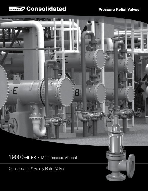
1900 Series - Maintenance Manual
1900 Series - Maintenance Manual
1900 Series - Maintenance Manual

Create successful ePaper yourself
Turn your PDF publications into a flip-book with our unique Google optimized e-Paper software.
Table of ContentsSection Subject Page NoXII. Reassembly ................................................................................................................................... 39General Information ................................................................................................................... 39Preparation ................................................................................................................................ 39Lubrication ................................................................................................................................ 39Reassembly Procedure .............................................................................................................. 39XIII. Setting and Testing ......................................................................................................................... 45General Information .................................................................................................................... 45Test Equipment ......................................................................................................................... 45Test Media ................................................................................................................................. 45Setting the Valve......................................................................................................................... 45Set Pressure Compensation ...................................................................................................... 45Seat Tightness Testing ............................................................................................................... 47XIV. Hydrostatic Testing and Gagging .................................................................................................... 49XV. <strong>Manual</strong> Popping of the Valve .......................................................................................................... 49XVI. Conversion of <strong>1900</strong> <strong>Series</strong> Flanged SRVs ................................................................................... 50General Information .................................................................................................................... 50Conversion from Conventional to Bellows Type .......................................................................... 50Conversion from Bellows to Conventional Type .......................................................................... 50XVII. Troubleshooting <strong>1900</strong> <strong>Series</strong> SRVs ............................................................................................ 53XVIII. <strong>Maintenance</strong> Tools and Supplies .................................................................................................... 53XIX. Replacement Parts Planning .......................................................................................................... 55Basic Guidelines ........................................................................................................................ 55Replacement Parts List .............................................................................................................. 55Identification and Ordering Essentials ......................................................................................... 55XX. Genuine Dresser Parts ................................................................................................................... 56XXI. Recommended Spare Parts for <strong>1900</strong> <strong>Series</strong> SRVs ..................................................................... 57XXII. Manufacturer’s Warranty, Field Service, Training, and Repair Program ............................................ 59Warranty Information .................................................................................................................. 59Field Service............................................................................................................................... 59Factory Repair Facilities .............................................................................................................. 59SRV <strong>Maintenance</strong> Training .......................................................................................................... 60XXIII. Self-Study Edition of the <strong>1900</strong> <strong>Series</strong> SRV <strong>Maintenance</strong> Training Program .................................. 60XXIV. Optional Glide-Aloy Parts ........................................................................................................... 61XXV. Sales Office Locations .................................................................................................................... 624 | Dresser Consolidated ®
I. Product Safety Sign and Label SystemIf and when required, appropriate safety labels have been included in therectangular margin blocks throughout this manual. Safety labels are verticallyoriented rectangles as shown in the representative examples (below),consisting of three panels encircled by a narrow border. The panels cancontain four messages which communicate:• The level of hazard seriousness• The nature of the hazard• The consequence of human, or product, interaction with the hazard.• The instructions, if necessary, on how to avoid the hazard.The top panel of the format contains a signal word (DANGER, WARNING,CAUTION or ATTENTION) which communicates the level of hazard seriousness.The center panel contains a pictorial which communicates the nature of thehazard, and the possible consequence of human or product interaction with thehazard. In some instances of human hazards the pictorial may, instead, depictwhat preventive measures to take, such as wearing protective equipment.The bottom panel may contain an instruction message on how to avoid thehazard. In the case of human hazard, this message may also contain a moreprecise definition of the hazard, and the consequences of human interactionwith the hazard, than can be communicated solely by the pictorial.1DANGER — Immediate hazardswhich WILL result in severepersonal injury or death.2WARNING — Hazards or unsafepractices which COULD result insevere personal injury or death.3CAUTION — Hazards or unsafepractices which COULD result inminor personal injury.4ATTENTION — Hazards orunsafe practices which COULDresult in product or propertydamage1 2 3 4Do not remove bolts ifpressure in line, as this willresult in severe personalinjury or death.Know all valve exhaust/leakage points to avoidpossible severe personalinjury or death.Wear necessary protectiveequipment to preventpossible injuryHandle valve carefully. Donot drop or strike.<strong>1900</strong> <strong>Series</strong> Safety Valve (July/2010) | 5
I. Product Safety Sign and Label System (Contd.)Safety Alerts! Read -Understand - PracticeDanger AlertsA DANGER alert describes actions that may causesevere personal injury or death. In addition, it mayprovide preventive measures to avoid severe personalinjury or death.DANGER alerts are not all-inclusive. Dresser cannotknow all conceivable service methods nor evaluate allpotential hazards. Dangers include:• High temperature/pressure can cause injury. Ensureall system pressure is absent before repairingor removing valves.• Do not stand in front of a valve outlet whendischarging. STAND CLEAR OF VALVE to avoidexposure to trapped, corrosive media.• Exercise extreme caution when inspecting apressure relief valve for leakage.• Allow the system to cool to room temperaturebefore cleaning, servicing, or repairing. Hotcomponents or fluids can cause severe personalinjury or death.• Always read and comply with safety labels on allcontainers. Do not remove or deface containerlabels. Improper handling or misuse could resultin severe personal injury or death.• Never use pressurized fluids/gas/air to cleanclothing or body parts. Never use body parts tocheck for leaks, flow rates, or areas. Pressurizedfluids/gas/air injected into or near the body cancause severe personal injury or death.from pressurized or heated parts. Contact withpressurized or heated parts can result in severepersonal injury or death.• Do not work or allow anyone under the influenceof intoxicants or narcotics to work on or aroundpressurized systems. Workers under the influenceof intoxicants or narcotics are a hazard tothemselves and other employees. Actions takenby an intoxicated employee can result in severepersonal injury or death to themselves or others.• Always perform correct service and repair.Incorrect service and repair can result in productor property damage or severe personal injury ordeath.• Always use the correct tool for a job. The misuseof a tool or the use of an improper tool can resultin personal injury, damage to product or property.• Ensure the proper “health physics” proceduresare followed, if applicable, before starting operationin a radioactive environment.Caution AlertsA CAUTION alert describes actions that may resultin a personal injury. In addition, they may describepreventive measures that must be taken to avoidpersonal injury. Cautions include:• Heed all service manual warnings. Read installationinstructions before installing valve(s).• Wear hearing protection when testing or operatingvalves.• Wear appropriate eye and clothing protection.• Wear protective breathing apparatus to protectagainst toxic media.• It is the owner’s responsibility to specify andprovide protective wear to protect persons6 | Dresser Consolidated ®
II. Terminology for Safety Relief Valves• Accumulation - the pressure increase over themaximum allowable working pressure of the vesselduring discharge through the SRV, expressed as apercentage of that pressure or in actual pressureunits.• Backpressure - the pressure on the discharge sideof the SRV:• Built-up Backpressure - the pressure thatdevelops at the valve outlet, after the SRV hasbeen opened, as a result of flow.• Superimposed Backpressure - the pressure inthe discharge header before the SRV is opened.• Constant Backpressure - the superimposedbackpressure that is constant with time.• Variable Backpressure - the superimposedbackpressure that varies with time.• Blowdown - the difference between set pressureand re-seating pressure of the SRV, expressed as apercentage of the set pressure or in actual pressureunits.• Cold Differential Set Pressure - the pressure atwhich the valve is adjusted to open on the teststand. This pressure includes the correctionsfor backpressure and/or temperature serviceconditions.• Differential Between Operating and Set PressuresValves in installed process services will generallygive best results if the operating pressure does notexceed 90% of the set pressure. However, on pumpand compressor discharge lines, the differentialrequired between the operating and set pressuresmay be greater because of pressure pulsationscoming from a reciprocating piston. The valveshould be set as far above the operating pressureas possible.• Lift - the actual travel of the disc away from theclosed position when a valve is relieving.• Maximum Allowable Working Pressure - themaximum gauge pressure permissible in a vesselat a designated temperature. A vessel may not beoperated above this pressure, or its equivalent, atany metal temperature other than that used in itsdesign. Consequently, for that metal temperature,it is the highest pressure at which the primarypressure SRV is set to open.• Operating Pressure - the gauge pressure towhich the vessel is normally subjected in service.A suitable margin is provided between operatingpressure and maximum allowable working pressure.For assured safe operation, the operating pressureshould be at least 10% under the maximumallowable working pressure or 5 psi (.34 bar),whichever is greater.• Overpressure - a pressure increase over theset pressure of the primary relieving device.Overpressure is similar to accumulation when therelieving device is set at the maximum allowableworking pressure of the vessel. Normally,overpressure is expressed as a percentage of setpressure.• Rated Capacity - the percentage of measured flowat an authorized percent overpressure permittedby the applicable code. Rated capacity is generallyexpressed in pounds per hour (lb/hr) for vapors,standard cubic feet per minute (SCFM) or m3/min for gases, and in gallons per minute (GPM) forliquids.• Relief Valve - an automatic pressure-relievingdevice, actuated by static pressure upstream fromthe valve. A relief valve is used primarily for liquidservice.• Safety Relief Valve (SRV) - an automatic pressurerelievingdevice used as either a safety or reliefvalve, depending upon application. The SRV is usedto protect personnel and equipment by preventingexcessive overpressure.• Safety Valve - an automatic pressure-relievingdevice actuated by the static pressure upstreamof the valve, and characterized by a rapid openingor “pop” action. It is used for steam, gas, or vaporservice.• Set Pressure - the gauge pressure at the valveinlet for which the relief valve has been adjustedto open under service conditions. In liquid service,the inlet pressure at which the valve starts todischarge determines set pressure. In gas or vaporservice, the inlet pressure at which the valve popsdetermines the set pressure.• Simmer - the audible passage of a gas or vaporacross the seating surfaces just before “pop.” Thedifference between this start-to-open pressureand the set pressure is called “simmer.” Simmeris generally expressed as a percentage of setpressure.<strong>1900</strong> <strong>Series</strong> Safety Valve (July/2010) | 7
III. IntroductionThe safety relief valve (SRV) is an automatic, pressureactuatedrelieving device suitable for use either as asafety valve or relief valve, depending on application.SRVs are used on hundreds of different applications,including liquids and hydrocarbons; therefore, the valveis designed to meet many requirements.The <strong>1900</strong> <strong>Series</strong> valves included in this manual maybe used to meet the requirements for ASME Section IIIand Section VIII. They cannot be used on ASME CodeSection I steam boilers or superheaters, but may beused on process steam.IV. Design Features andNomenclatureCap and Lever InterchangeabilityIn the field, it is often necessary to change the type ofcap or lever after a valve has been installed. All flangedConsolidated ® SRVs are designed to be converted toany type of lever or cap desired. It is not necessary toremove the SRV from the installation, nor will the setpressure be affected when making such a change.Design SimplicityConsolidated ® SRVs have few component parts,resulting in savings by minimizing spare parts inventoryand simplifying valve maintenance.Nomenclature Related to Design FeaturesThe nomenclature of the components of <strong>1900</strong> <strong>Series</strong>valves, including those with design options for universalmedia, universal media soft-seat bellows, O-ring seat,liquid trim, and Thermodisc ® , is identified in Figures 1through 10.Simple Blowdown AdjustmentThe Consolidated ® single blowdown ring design makesit possible to set and test a valve at the customer’sshop when it is impractical to set and media may bevery low, the ring can be positioned so that the setpoint can be observed without damaging the valve.Blowdown can be attained by positioning the ring inaccordance with the adjusting ring position (see Tables12 through 14).Valve InterchangeabilityA standard Consolidated ® SRV may be converted tothe universal media, universal media soft-seat bellowstype, the O-ring seat seal type, etc., and vice versa.Should conversion be required, this interchangeabilitylowers costs and requires fewer new parts thanreplacing entire valve types.8 | Dresser Consolidated ®
V. Consolidated ® <strong>1900</strong> <strong>Series</strong> Safety Relief ValveV.1 Metal Seat Valve1921PartNo.Nomenclature271718151716121098763452118763201141131440421A1/2” - NPTDRAINFigure 1: Conventional Metal Seat Valve1 Base2 Nozzle3 Adjusting Ring4 Adjusting Ring Pin5 Adjusting Ring Pin Gasket6 Disc7 Disc Retainer8 Disc Holder9 Guide10 Guide Gasket11 Bonnet12 Bonnet Gasket13 Base Stud14 Stud Nut15 Spindle16 Spindle Retainer17 Spring Washer18 Spring19 Adjusting Screw20 Adjusting Screw Locknut21 Screwed Cap27 Cap Gasket40 Eductor Tube41 Bonnet Plug42 Limit Washer452Figure 2: UM Metal Seat Valve<strong>1900</strong> <strong>Series</strong> Safety Valve (July/2010) | 9
V. (Contd.)V.1.1 Standard Cap Types2329PartNo.Nomenclature10 | Dresser Consolidated ®312822 Bolted Cap3223 Packed Cap333024 Plain Cap342525 Cap Bolt2726 Cap Set Screw27 Cap GasketFigure 3: Packed Cap28 Release Nut2429 Release Locknut282930 Lever3531 Lifting Fork3632 Lever Shaft2633 Packing34 Packing Nut35 Top Lever36 Drop Lever37 Gag38 Sealing PlugFigure 4: Plain Cap39 Sealing Plug Gasket373839222527Figure 5: Bolted CapFigure 6: Cap with Gag
V. (Contd.)V.2 Bellows Metal Seat Valve192717181517161210987634521441A1/2” - NPTDRAIN1/2” - NPTVENTFigure 7: Bellows Metal Seat Valve Construction212011131443PartNo.1 Base1ANomenclatureBase Plug2 Nozzle3 Adjusting Ring4 Adjusting Ring Pin5 Adjusting Ring Pin Gasket6 Disc7 Disc Retainer8 Disc Holder9 Guide10 Guide Gasket11 Bonnet12 Bonnet Gasket13 Base Stud14 Stud Nut15 Spindle16 Spindle Retainer17 Spring Washer18 Spring19 Adjusting Screw20 Adjusting Screw Locknut21 Screwed Cap27 Cap Gasket43 Bellows44 Bellows gasketBellowsFlangeBellowsBellowsRingFigure 8: Bellows Assembly<strong>1900</strong> <strong>Series</strong> Safety Valve (July/2010) | 11
V. (Contd.)V.3 V-W Bellows Metal Seat ValvePartNo.Nomenclature24513520583617181715118121060 2686345211ADRAIN38392528264360Figure 9: V & W Orifice Valve Construction76153½” - NPTDrain13144844371 Base2 Nozzle3 Adjusting Ring4 Adjusting Ring Pin5 Adjusting Ring Pin Gasket6 Disc7 Disc Retainer8 Disc Holder9 Guide10 Guide Gasket11 Bonnet12 Bonnet Gasket13 Base Stud14 Stud Nut15 Spindle16 Spindle Retainer17 Spring Washer18 Spring19 Adjusting Screw20 Compression Screw Locknut24 Plain Cap25 Cap Bolt26 Cap Set Screw27 Cap Gasket28 Release Gasket35 Top Lever36 Drop Lever37 Gag38 Sealing Plug39 Sealing Plug Gasket43 Bellows44 Bellows gasket48 Guide RIngs51 Compression Screw53 Spring Plunger58 Clevis59 Eye Bolt60 Lockscrew Washer (Bellows)61 Retainer Screw Lockwasher12 | Dresser Consolidated ®
V. (Contd.)V.4 Soft Seat ValveConventional O-Ring Soft Seat Valve84349545523843764955543Figure 10a: D - J Orifice2Figure 10b: K-T Orifice87PartNo.Nomenclature2 Nozzle3 Adjusting Ring6 Disc7 Disc Retainer8 Disc Holder43 Bellows49 Disc Retainer Screws54 O-Ring Retainer55 O-Ring Seat Seal56 Soft Seat retainer57 Teflon Steel649565732Figure 10c: UM Teflon SealFigure 10: Soft Seat Valve Construction<strong>1900</strong> <strong>Series</strong> Safety Valve (July/2010) | 13
VI. Handling, Storage, and Pre-InstallationHandlingStorageAlways keep the inlet flang down on a crated or uncratedflang valve to prevent misalignment and damageto valve internals.ATTENTION!!Never lift the full weight of the valve by thelifting lever.ATTENTION!!Do not rotate the valve horizontally or lift/carryusing the lifting lever.Store SRVs in a dry environment and protect them fromthe weather. Do not remove the valve from the skids orcrates until immediately before installation.Do not remove flang protectors and seating plugs untilthe valve is ready to be bolted into place during theinstallation.Pre-InstallationWhen SRVs are uncrated and the flang protectors orsealing plugs are removed, exercise meticulous care toprevent dirt and other foreign materials from entering theinlet and outlet ports while bolting the valve in place.vWrap a chain or sling around the discharge neck andaround the upper bonnet structure to move or hoist anuncrated valve. Ensure the valve is in a vertical positionduring the lift.ATTENTION!!Handle carefully. Do not drop or strike the valve.Do not subject SRVs, either crated or uncrated, to sharpimpact. Ensure that the valve is not bumped or droppedduring loading or unloading from a truck. While hoistingthe valve, take care to prevent bumping the valveagainst steel structures and other objects.ATTENTION!!Prevent dust and debris from entering inlet or outletof the valve.14 | Dresser Consolidated ®
VII. Recommended Installation PracticesMounting PositionMount safety relief valvesin a vertical, uprightposition only.Do not mount valve atthe end of pipe throughwhich there is normally noflow or near elbows, tees,bends, etc.Mount SRVs in a vertical (upright) position (in accordance with API RP 520). Installinga safety relief valve in any position other than vertical (±1 degree) will adverselyaffect its operation as a result of the induced misalignment of moving parts.A stop valve may be placed between the pressure vessel and its relief valve only aspermitted by code regulations. If a stop valve is located between the pressure vesseland SRV, the stop valve port area should equal or exceed the nominal internal areaassociated with the pipe size of the SRV inlet. The pressure drop from the vessel tothe SRV shall not exceed 3% of the valve’s set pressure, when flowin at full capacity.Ensure the flange and sealing faces of the valve and connective piping are freefrom dirt, sediment, and scale.Ensure all flang bolts are drawn evenly to prevent distortion of the valve body andthe inlet nozzle.Position SRVs for easy access and/or removal so that servicing can be properlyperformed. Ensure sufficien working space is provided around and above the valve.Inlet PipingThe inlet piping (see Figure 11) to the valve should be short and directly from thevessel or equipment being protected. The radius of the connection to the vesselshould permit smooth flo to the valve. Avoid sharp corners. If this is not practical,then the inlet should be at least one additional pipe diameter larger.The pressure drop from the vessel to the valve shall not exceed 3% of valve setpressure when the valve is allowing full capacity flo. The inlet piping should neverbe smaller in diameter than the inlet connection of the valve. Excessive pressuredrop in gas, vapor, or flashing-liqui service at the inlet of the SRV will cause theextremely rapid opening and closing of the valve, which is known as “chattering.”Chattering will result in lowered capacity and damage to the seating surfaces. Themost desirable installation is that in which the nominal size of the inlet piping is thesame as, or greater than, the nominal size of the valve inlet flange and in whichthe length does not exceed the face-to-face dimensions of a standard tee of therequired pressure class.Do not locate SRV inlets where excessive turbulence is present, such as nearelbows, tees, bends, orifice plates or throttling valves.Section VIII of the ASME Boiler and Pressure Vessel Code requires the inletconnection design to consider stress conditions during valve operation, caused byexternal loading, vibration, and loads due to thermal expansion of the dischargepiping.The determination of reaction forces during valve discharge is the responsibility ofthe vessel and/or piping designer. Dresser publishes certain technical informationabout reaction forces under various flui flo conditions, but assumes no liability forthe calculations and design of the inlet piping.Heed all servicemanual warnings. Readinstallation instructionsbefore installing valve(s).External loading, by poorly designed discharge piping and support systems, andforced alignment of discharge piping can cause excessive stresses and distortionsin the valve as well as the inlet piping. The stresses in the valve may cause amalfunction or leak. Therefore, discharge piping must be independently supportedand carefully aligned.Vibrations in the inlet piping systems may cause valve seat leakage and/or fatigue<strong>1900</strong> <strong>Series</strong> Safety Valve (July/2010) | 15
VII. Recommended Installation Practices (Contd.)P.D.StopValveP.D.P.D.Vessel Vessel VesselFigure 11: Pressure Drop on the Inlet PipingThe pressuredrop (P.D.)between thesource ofpressure in theprotectedequipment andthe pressure reliefvalve inlet is notto exceed 3% ofthe valve setpressure.P.D.From Protected Equipmentfailure. These vibrations may cause the disc seat to slideback and forth across the nozzle seat and may resultin damage to the seating surfaces. Also, vibration maycause separation of the seating surfaces and prematurewear to valve parts. High-frequency vibrations aremore detrimental to SRV tightness than low-frequencyvibrations. This effect can be minimized by providing alarger difference between the operating pressure of thesystem and the set pressure of the valve, particularlyunder high frequency conditions.Temperature changes in the discharge piping may becaused by flui flowin from the discharge of the valve orby prolonged exposure to the sun or heat radiated fromnearby equipment. A change in the discharge pipingtemperature will cause a change in the length of thepiping, which may cause stresses to be transmitted tothe SRV and its inlet piping. Proper support, anchoringor provision for flexibilit of the discharge piping canprevent stresses caused by thermal changes. Do notuse fixe supports.Outlet PipingAlignment of the internal parts of the SRV is importantto ensure proper operation (see Figure 12). Althoughthe valve body will withstand a considerable mechanicalload, unsupported discharge piping consisting of morethan a companion flange long-radius elbow, and a shortvertical pipe is not recommended. Use spring supportsto connect outlet piping to prevent thermal expansionfrom creating strains on the valve. The discharge pipingshould be designed to allow for vessel expansion aswell as expansion of the discharge pipe itself. This isparticularly important on long distance lines.A continual oscillation of the discharge piping (windloads) may induce stress distortion in the valve body.The resultant movement of the valve’s internal parts maycause leakage.Where possible, use properly supported drainage pipingto prevent the collection of water or corrosive liquid inthe valve body.When two or more valves are piped to discharge intoa common header, the built-up backpressure resultingfrom the opening of one (or more) valve(s) may causea superimposed backpressure in the remaining valves.Under these conditions, the use of bellows valves isrecommended. The use of bellows valves may alsopermit the use of a smaller-size manifold.In every case, the nominal discharge pipe size shouldbe at least as large as the nominal size of the SRV outletflange In the case of long discharge piping, the nominaldischarge pipe size must sometimes be much larger.ATTENTION!!All non-bellows valves should have a bonnet pluginstalled. Bellows valves must have an open bonnetvent.16 | Dresser Consolidated ®
VIII. Disassembly InstructionsCap may requiredfor weatherprotectionFor a closed system, alwayskeep piping strains isolatedfrom the pressure reliefvalve, regardless of processoperation and temperature.Attach Stacky rigidly to structure.Do not connect to drain pan or thediscarge pipingStackDrainPanWRONGWear necessaryprotective equipment toprevent possible injuryLong-RadiusElbowGeneral InformationPan DrainLong-RadiusElbowVessel Vessel VesselFigure 12: SRV Parts AlignmentConsolidated ® SRVs can be easily disassembledfor inspection, the reconditioning of seats or thereplacement of internal parts. Appropriate setpressure can be established after reassembly. (SeeFigures 1 through 10 for parts nomenclature.)ATTENTION!!Before disassembling thevalve, ensure there is no mediapressure in the vessel.Valve caps and bonnetscan trap fluids. Usecaution when removingto prevent injury orenvironmental damage.Do not interchange parts from one valve withparts from another valve.SRV Disassembly1. If equipped, remove the lifting lever gear as follows:• Plain Lever (see Figure 40) Remove cotter pin, lever pin and plain lever[one-piece design] or top lever [two-piecedesign].• Packed Lever (see Figures 41 and 42) Disassembly not required. Rotate leverMany pressure vesselsprotected by Consolidated®Safety Relief Valves containdangerous materials.Decontaminate and cleanthe valve inlet, outlet, andall external surfaces inaccordance with the cleaningand decontaminatingrecommendations in theappropriate Material SafetyData Sheet.counterclockwise, positioning lifting fork so that it clears release nut duringcap removal.2. Remove the cap.3. Remove the cap gasket (27), if applicable.4. Remove adjusting ring pin (4) and adjusting ring pin gasket (5).5. If the existing blowdown is to be restored upon reassembly, determine theposition of the adjusting ring (3) with respect to the disc holder (8) as follows:• Turn the adjusting ring counterclockwise (move notches on the adjusting ringfrom left to right).• Record the number of notches that pass the ring pinhole before the ringcontacts the disc holder.<strong>1900</strong> <strong>Series</strong> Safety Valve (July/2010) | 17
VIII. Disassembly Instructions (Contd.)ATTENTION!!This procedure does not substitute for actualpressure testing.6. Follow the procedure appropriate to the orifice valve type:• Using a depth micrometer or a dial caliper, measurethe distance from the top of the spindle (15) tothe top of the adjusting screw (19). This allowsthe adjusting screw to be readjusted close to theproper spring compression without excessivetesting.• Record the measurement for reference whenreassembling the valve.• D through U orifice valves: Loosen the adjusting screw locknut (20). Remove the adjusting screw from the bonnet(11). Use pliers to prevent the spindle fromturning when removing the adjusting screw.• V and W orifice valves: Attach the setting device (see Figure 13). Apply enough pressure to the plunger using theram to free the adjusting screw. Loosen the adjusting screw locknut. Completely unscrew the adjusting screw fromthe bonnet.ATTENTION!!Set the valve using the setting procedures afterreassembly.Hydraulic Jack Cap Screw NutAdaptorSetting PlateNut21” (533.40 mm)Spring PlungerBonnetSpindleGuageHose Hydraulic PumpStudAdjusting ScrewNutPlunger retainerused to holdAdj. Screw andSpring Plungertogethorduring assemblyFigure 13: Setting Device for V and W Orifice7. Remove the stud nuts (14) and lift off the bonnet (11).8. Remove the bonnet gasket (12).9. Remove the spring (18) and the spring washers (17).Keep the spring and spring washers together, as aunit, at all times.10. Follow the procedure appropriate to the valve type:• D through L orifice valves: Remove the upper internal parts by carefullypulling “straight up” on the spindle (15). Forbellows valves, take care to avoid damagingthe bellows or its flange If parts are fouled use asuitable solvent for loosening the components. Clamp the skirt portion of the disc holder (8)snugly between two wooden V-blocks in asuitable vise. Compress the spindle retainer (16) with ascrewdriver or similar tool through the slotsprovided and remove the spindle.ATTENTION!!Special lifting tools are available for ease of upperinternal part removal• M through U orifice valves: Use a screwdriver to compress the spindleretainer (16). Remove the spindle (15). Insert the lifting tool (see Figure 10a) into the discholder spindle pocket and tighten the eyebolt. Remove the disc holder (8) and disc (6) by liftingup on the lifting tool.• Valve V and W orifice valve: Use the lifting lugs to lift the disc holder (8) and toremove all internals (see Figure 14b).11. Remove the guide (9) from the disc holder (8). (Forrestricted lift valves, see Checking Lift on RestrictedLift Valves. For V and W orifice unbolt the bellowsfrom guide before guide removal.12. For D through U orifice bellows valves (see Figure7), the bellows is attached to the disc holder (8)by right-hand threads. Use a special spannerwrench on the bellows ring to remove it by turningcounterclockwise (see Figure 15).18 | Dresser Consolidated ®
VIII. Disassembly Instructions (Contd.)ATTENTION!!The nozzle (2) is normally removed for routinemaintenance and service.17. The nozzle (2) is threaded onto the base (1) and isremoved by turning it counterclockwise (from right toleft). Before removing the nozzle, soak the threaded jointwith a suitable penetrating liquid or solvent. If the nozzleis frozen to the base, apply dry ice or other cooling mediumto the inside of the nozzle and heat the base fromthe outside with a blowtorch in the area of the nozzlethreads.ATTENTION!!Should heat be applied, use care to preventcracking of cast parts.18. Using a three- or four-jaw chuck welded vertically toa stand bolted to a concrete floor, clamp the nozzle (2)into the chuck and break the body loose with a heavyrod or pipe (see Figure 17).ATTENTION!!Exercise care when inserting a rod or pipe in theoutlet. Ensure the valve nozzle is not damagedduring the operation.19. Use a large pipe wrench on the nozzle flang toremove the nozzle (2) from the base (1) (see Figure 18).View From TopView From SidePipe WrenchIX. CleaningNozzleBaseFigure 18: Removing the Nozzle from the Base<strong>1900</strong> <strong>Series</strong> SRV internal parts may be cleaned withindustrial solvents, cleaning solutions, and wire brushes.If cleaning solvents are used, take precautions to protectyourself from potential danger from fume inhalation,chemical burns, or explosion. See the solvent’sMaterial Safety Data Sheet (MSDS) for safe handlingrecommendations and equipment.Do not sandblast internal parts because it can reducethe dimensions of the parts. The base (1), bonnet (11),and screwed cap (21) may be sandblasted, but takecare not to erode internal surfaces or damage machinedsurfaces.Base8' (2.4 m)-10' (3 m)Long Rod orHeavy PipeNozzle3 Jaw ChuckChuck StandFigure 17: Loosening the Nozzle from the BaseFollow recommendations forsafe handling in the solvent’sMaterial Safety Data Sheet andobserve safe practices for anycleaning method.20 | Dresser Consolidated ®
X. Parts InspectionNozzle Inspection CriteriaNozzle should be replaced if:• Dimension from seat to first thread, after remachiningand lapping, is less than D min.(see Table 1).• Threads are damaged from pitting and/or corrosion.• Top of flang and intersecting surface are damagedfrom galling and/or tearing.• Seat width is outside specification (see Tables 7a,7b or 7c).Nozzle Seat WidthUsing a measuring magnifying glass (see LappedNozzle Seat Widths), determine whether the seatingsurface must be machined before lapping. If the seatcan be lapped flat without exceeding the requiredseat width (see Tables 7a, 7b or 7c), it does notrequire machining. To reduce the seat width, the 5ºangle surface must be machined. The nozzle mustbe replaced if the D dimension is reduced below theminimum (see Table 1).ATTENTION!!Flange thickness changes the center-to-facedimension. Ensure the minimum dimension for orificeD through P is .656" (16.67 mm), and for Q throughW is .797" (20.24 mm).Nozzle Bore InspectionAll <strong>1900</strong> <strong>Series</strong> SRV nozzles manufactured afterAugust 1978 have increased bore diameters. Originaland new nozzles are interchangeable, but the ratedcapacities are different (see Table 2).<strong>1900</strong> TM <strong>Series</strong> SRV StandardDisc Inspection AreasThe standard <strong>1900</strong> TM <strong>Series</strong> disc (see Figure 20) canbe machined until the N dimension is reduced to itsminimum size (see Table 3). The T dimension is providedto ensure the disc has not been machined beyond itslimits. If re-machining reduces the thickness of the disc(T min.), the entire disc holder assembly drops withrespect to the seating plane of the nozzle. This creates asignificant change in the huddle chamber configurationand results in significantly more simmer before opening.<strong>1900</strong> TM <strong>Series</strong> Thermodisc ®Replacement CriteriaThe Thermodisc ® must be replaced if:• Seat defects and damage cannot be lapped outwithout reducing the A dimension below those listedin Table 4 (see Figure 21).ATTENTION!!The A dimension on orifice D through H is difficult tomeasure. If the .006" (0.15 mm) minimum thicknessof the thermal lip cannot be measured, replace theThermodisc ® .5 0 ACBL5°FHNMAKLBDED minJ45 0 D minNozzleBorePNozzle BoreNozzleBoreFigure 19a: MetalSeated NozzleFigure 19b: O-RingSeal NozzleFigure 19: Metal Seated and O-Ring NozzlesFigure 19c: Soft-SeatO-Ring Nozzle<strong>1900</strong> <strong>Series</strong> Safety Valve (July/2010) | 21
X. Parts Inspection (Contd.)OrificeD-2,E-2, FTable 1a: Nozzle Critical Dimensions (Metal Seated Nozzle)E ± .005"D min.F H N(±0.13 mm)P±0.5°in. mm in. mm in. mm in. mm in. mm.399 10.13 .030 0.76 .954 ± .001 24.23 ± 0.03 .831 ± .001 21.11 ± 0.03 .038 + - .002.003 0.97 + - 0.050.08 30°G .399 10.13 .035 0.89 1.093 ± .001 27.76 ± 0.03 .953 ± .001 24.21 ± 0.03 .037 + - .003.002 0.94 + - 0.080.05 30°H .305 7.75 .035 0.89 1.224 ± .001 31.09 ± 0.03 1.123 ± .001 28.52 ± 0.03 .035 + - .002.003 0.89 + - 0.050.08 45°J .430 12.50 .035 0.89 1.545 ± .001 39.24 ± 0.03 1.435 ± .001 36.45 ± 0.03 .035 ± .005 0.89 ± 0.13 45°K .492 12.50 .063 1.60 1.836 ± .002 46.63 ± 0.05 1.711 ± .002 43.46 ± 0.05 .063 ± .005 1.60 ± 0.13 45°L .492 12.50 .063 1.60 2.257 ± .002 57.33 ± 0.05 2.133 ± .002 54.18 ± 0.05 .063 ± .005 1.60 ± 0.13 45°M .492 12.50 .063 1.60 2.525 ± .002 64.14 ± 0.05 2.4 ± .002 60.96 ± 0.05 .063 ± .005 1.60 ± 0.13 45°N .555 14.10 .063 1.60 2.777 ± .002 70.54 ± 0.05 2.627 ± .002 66.73 ± 0.05 .063 ± .005 1.60 ± 0.13 45°P .680 17.27 .093 2.36 3.332 ± .002 84.63 ± 0.05 3.182 ± .002 80.82 ± 0.05 .093 ± .005 2.36 ± 0.13 45°Q .930 23.62 .093 2.36 4.335 ± .003 110.11 ± 0.08 4.185 ± .003 106.30 ± 0.08 .093 ± .005 2.36 ± 0.13 45°R 1.055 26.80 .093 2.36 5.110 ± .003 129.79 ± 0.08 4.96 ± .003 125.98 ± 0.08 .093 ± .005 2.36 ± 0.13 45°T-4 .805 20.45 .093 2.36 6.510 ± .003 165.35 ± 0.08 6.315 ± .003 160.40 ± 0.08 .093 ± .005 2.36 ± 0.13 45°U .805 20.45 .093 2.36 6.993 ± .003 177.62 ± 0.08 6.798 ± .003 172.67 ± 0.08 .093 ± .005 2.36 ± 0.13 45°V 1.305 33.15 .250 6.35 8.816 ± .005 223.93 ± 0.13 8.336 ± .005 211.73 ± 0.13 .275 ± .005 6.99 ± 0.13 30°W 1.805 45.85 .350 8.89 11.058 ± .005 280.87 ± 0.13 10.458 ± .005 265.63 ± 0.13 .353 ± .005 8.97 ± 0.13 30°OrificeD-2,E-2, FTable 1b: Nozzle Critical Dimensions (O-Ring Seat Nozzle)J ± .005”D min. B (Radius)KL(±0.13 mm)in. mm in. mm in. mm in. mm in. mm.399 10.13 .016 ± .001 0.41 ± 0.03 .079 2.01 .867 ± .001 22.02 ± 0.03 .813 ± .001 20.65 ± 0.03G .399 10.13 .022 ± .001 0.56 ± 0.03 .090 2.29 1.058 + - .002.00126.87 + - 0.050.03H .305 7.75 .022 ± .001 0.56 ± 0.03 .060 1.52 1.214 + - .002.00130.84 + - 0.050.031.165 + - .002.001J .430 12.50 .022 ± .001 0.56 ± 0.03 .074 1.88 1.532 + .002- .00138.91 + 0.05- 0.031.479 + .002- .001K .492 12.50 .022 ± .001 0.56 ± 0.03 .126 3.20 1.836 ± .002 46.63 ± 0.05 1.780 + - .001.002.998 ± .001 25.35 ± 0.0329.59 + - 0.050.0337.57 + 0.05- 0.0345.21 + - 0.030.05L .492 12.50 .017 ± .001 0.43 ± 0.03 .126 3.20 2.206 ± .002 56.03 ± 0.05 2.156 ± .002 54.76 ± 0.05M .492 12.50 .022 ± .001 0.56 ± 0.03 .126 3.20 2.534 ± .002 64.36 ± 0.05 2.478 ± .002 62.94 ± 0.05N .555 14.10 .022 ± .001 0.56 ± 0.03 .101 2.57 2.706 ± .002 68.73 ± 0.05 2.650 ± .002 67.31 ± 0.05P .680 17.27 .022 ± .001 0.56 ± 0.03 .150 3.81 3.332 ± .002 84.63 ± 0.05 3.277 + - .002.00383.24 + - 0.050.08Q .930 23.62 .022 ± .001 0.56 ± 0.03 .188 4.78 4.335 ± .003 110.11 ± 0.08 4.281 ± .003 108.74 ± 0.08R 1.055 26.80 .022 ± .001 0.56 ± 0.03 .215 5.46 5.092 ± .003 129.34 ± 0.08 5.033 ± .003 127.84 ± 0.08T-4 .805 20.45 .022 ± .001 0.56 ± 0.03 .142 3.61 6.510 + - .003.004 165.35 + - 0.080.106.420 + - .004.003 163.07 + - 0.100.08U .805 20.45 .022 ± .001 0.56 ± 0.03 .142 3.61 6.992 ± .003 177.60 ± 0.08 6.902 ± .003 175.31 ± 0.08V 1.305 33.15 .020 ± .001 0.51 ± 0.03 .275 6.99 9.125 ± .005 231.78 ± 0.13 8.336 ± .005 211.73 ± 0.13W 1.805 45.85 .020 ± .005 0.51 ± 0.13 .353 8.97 11.125 ± .005 282.58 ± 0.13 10.458 ± .005 265.63 ± 0.1322 | Dresser Consolidated ®
X. Parts Inspection (Contd.)OrificeTable 1c: Nozzle Critical Dimensions (UM Soft-Seat Nozzle)D min. A B Cin. mm in. mm in. mm in. mmD .313 7.95 .906 23.01 .831 21.11 .026 0.66E .313 7.95 .906 23.01 .831 21.11 .026 0.66F .313 7.95 .906 23.01 .831 21.11 .026 0.66G .313 7.95 1.039 26.39 .953 24.21 .030 0.76H .250 6.35 1.224 31.09 1.123 28.52 .035 0.89J .375 9.53 1.564 39.73 1.435 36.45 .045 1.14K .438 11.13 1.866 47.40 1.712 43.48 .053 1.35L .438 11.13 2.325 59.06 2.133 54.18 .066 1.68M .438 11.13 2.616 66.45 2.400 60.96 .075 1.91N .500 12.70 2.863 72.72 2.627 66.73 .082 2.08P .625 15.88 3.468 88.09 3.182 80.82 .099 2.51Q .875 22.23 4.561 115.85 4.185 106.30 .130 3.30R 1.000 25.40 5.406 137.31 4.960 125.98 .155 3.94T .750 19.05 6.883 174.83 6.315 160.40 .197 5.00U .750 19.05 7.409 188.19 6.798 172.67 .212 5.38V 1.250 31.75 9.086 230.78 8.336 211.73 .260 6.60W 1.750 44.45 11.399 289.53 10.458 265.63 .326 8.28OrificeTable 2: Nozzle Bore DiameterPre-1978Currentmin. max. min. max.Std. UM in. mm in. mm in. mm in. mmD-2 D .650 16.51 .655 16.64 .674 17.12 .679 17.25E-2 E .650 16.51 .655 16.64 .674 17.12 .679 17.25F F .650 16.51 .655 16.64 .674 17.12 .679 17.25G G .835 21.21 .840 21.34 .863 21.92 .868 22.05H H 1.045 26.54 1.050 26.67 1.078 27.38 1.083 27.51J J 1.335 33.91 1.340 34.04 1.380 35.05 1.385 35.18K K 1.595 40.51 1.600 40.64 1.650 41.91 1.655 42.04L L 1.985 50.42 1.990 50.55 2.055 52.20 2.060 52.32M M 2.234 56.74 2.239 56.87 2.309 58.65 2.314 58.78N N 2.445 62.10 2.450 62.23 2.535 64.39 2.540 64.52P P 2.965 75.31 2.970 75.44 3.073 78.05 3.078 78.18Q Q 3.900 99.06 3.905 99.19 4.045 102.74 4.050 102.87R R 4.623 117.42 4.628 117.55 4.867 123.62 4.872 123.75T-4 T - - - - 6.202 157.53 6.208 157.68U U - - - - 6.685 169.80 6.691 169.95V V - - - - 8.000 203.20 8.005 203.33W W - - - - 10.029 254.74 10.034 254.86Note: If an old style nozzle is machined to the new configuration, it should be done to a 63 micro inchfinish and shall be concentric and parallel to the original centerline within .004” (0.10 mm)T.I.R.<strong>1900</strong> <strong>Series</strong> Safety Valve (July/2010) | 23
X. Parts Inspection (Contd.)TTTN minN minBN minBBCC90 0LLType 1 Type 2 Type 3CFigure 20a: D - H Orifice DiscsD - U Orifice Discs (UM)Figure 20b:J - U Orifice DiscsFigure 20c: V & W Orifice Discs(Std. & UM)Figure 20: Disc Inspection AreasDiscTypeTable 3a: Minimum Dimensions afterMachining of the Disc Seat (Standard)OrificeT min.N min.in. mm in. mmD-2 .182 4.62 .015 0.38E-2 .182 4.62 .015 0.38Table 3b: Minimum Dimensions afterMachining of the Disc Seat (Universal Media)DiscTypeOrificeT min.N min.in. mm in. mmD .177 4.50 .012 0.30E .177 4.50 .012 0.30Type 1F .182 4.62 .015 0.38G .182 4.62 .015 0.38H .343 8.71 .018 0.46J .369 9.37 .020 0.51K .432 10.97 .048 1.22F .177 4.50 .012 0.30G .172 4.37 .015 0.38H .345 8.76 .020 0.51J .408 10.36 .028 0.71K .480 12.19 .036 0.91L .467 11.86 .048 1.22M .467 11.86 .048 1.22Type 1L .533 13.54 .053 1.35M .545 13.84 .060 1.52Type 2Type 3N .495 12.57 .048 1.22P .620 15.75 .078 1.98Q .620 15.75 .078 1.98R .620 15.75 .078 1.98T-4 .832 21.13 .078 1.98U .833 21.16 .078 1.98V 1.230 31.24 .120 3.05W 1.855 47.12 .168 4.27N .582 14.78 .064 1.63P .718 18.24 .075 1.91Q .750 19.05 .102 2.59R .772 19.61 .123 3.12T 1.016 25.81 .159 4.04U 1.022 25.96 .172 4.37Type 3 V 1.261 32.03 .213 5.41W 1.891 48.03 .269 6.8324 | Dresser Consolidated ®
X. Parts Inspection (Contd.)AFigure 21a: D - H OrificesAFigure 21b: J - W OrificesFigure 21: Thermodisc ® Design (D - W Orifices)Table 4: Minimum A Dimensions(Thermodisc ® )Orificein.A min.mmD .006 0.15E .006 0.15F .006 0.15G .006 0.15H .006 0.15J .013 0.33K .014 0.36L .014 0.36M .014 0.36N .014 0.36P .017 0.43Q .015 0.38R .015 0.38T-4 .025 0.64U .025 0.64V .033 0.84W .033 0.84<strong>1900</strong> <strong>Series</strong> Safety Valve (July/2010) | 25
X. Parts Inspection (Contd.)Disc Holder Inspection CriteriaSeveral disc holder designs are available, depending on the service and the type of valve (see Figure 22).For identification, the G diameter (Dia.) is provided (see Tables 5a and 5b).G Dia. (max.)Figure 22a: Detail 1Standard Disc Holder45 0G Dia. (max.)Figure 22b: Detail 2O-Ring Disc HolderG Dia. (max.)Figure 22c: Detail 3Liquid Service Disc Holder(LA Design)G Dia. (max.)Figure 22d: Detail 4O-Ring Liquid Service (DALA Design)D-2, E-2, F & G OrificeG Dia. (max.)Figure 22e: Detail 5O-Ring Liquid Service (DALADesign) - H & J OrificeG Dia. (max.)Figure 22f: Detail 6Universal Media Service(UM Design)Figure 22: Disc Holder Designs26 | Dresser Consolidated ®
X. Parts Inspection (Contd.)OrificeLowPressureTable 5a: Maximum Inside Diameter (G) for Disc Holder IdentificationStandard Disc HolderO-Ring Disc HolderAirg/Gas Trim Liquid Trim Air/Gas Trim Liquid TrimHighPressureLS DesignLA DesignLowPressureHighPressureDL DesignDALADesignin. mm in. mm in. mm in. mm in. mm in. mm in. mm in. mmD-2 1.167 29.64 1.032 26.21 1.167 29.64 1.265 3 32.13 3 1.105 2 28.07 2 1.032 26.21 1.032 26.21 1.092 4 27.74 4E-2 1.167 29.64 1.032 26.21 1.167 29.64 1.265 3 32.13 3 1.105 2 28.07 2 1.032 26.21 1.032 26.21 1.092 4 27.74 4F 1.167 29.64 1.032 26.21 1.167 29.64 1.265 3 32.13 3 1.105 2 28.07 2 1.032 26.21 1.032 26.21 1.092 4 27.74 4G 1.272 32.31 1.183 30.05 1.272 32.31 1.375 3 34.93 3 1.275 2 32.39 2 1.183 30.05 1.272 32.31 1.265 4 32.13 4H 1.491 37.87 1.394 35.41 1.491 37.87 1.656 3 42.06 3 1.494 2 37.95 2 1.394 35.41 1.491 37.87 1.494 5 37.95 5J 1.929 49.00 1.780 45.21 1.929 49.00 2.156 3 54.76 3 1.856 2 47.14 2 1.780 45.21 1.929 49.00 2.155 4 54.74 4K 2.126 54.00 2.126 54.00 2.264 57.51 2.469 3 62.71 3 2.264 57.51 2.264 57.51 2.264 57.51 2.469 3 62.71 3L 2.527 64.19 2.527 64.19 2.762 70.15 3.063 3 77.80 3 2.527 64.19 2.527 64.19 2.762 70.15 3.063 3 77.79 3M 2.980 75.69 2.980 75.69 3.054 77.57 3.359 3 85.32 3 2.980 75.69 2.980 75.69 3.054 77.57 3.359 3 85.32 3N 3.088 78.44 3.088 78.44 3.480 88.39 3.828 3 97.23 3 3.088 78.44 3.088 78.44 3.480 88.39 3.828 3 97.23 3P 3.950 100.33 3.950 100.33 4.361 110.77 4.813 3 122.25 3 3.950 100.33 3.950 100.33 4.361 110.77 4.813 3 122.25 3Q 5.197 132.00 5.197 132.00 5.546 140.87 6.109 3 155.17 3 5.197 132.00 5.197 132.00 5.546 140.87 6.109 3 155.18 3R 6.155 156.34 6.155 156.34 6.563 166.70 7.219 3 183.36 3 6.155 156.34 6.155 156.34 6.563 166.70 7.219 3 183.36 3T-4 7.841 199.16 7.841 199.16 - - 8.625 3 219.08 3 7.841 199.16 7.841 199.16 - - 8.625 3 219.08 3U 8.324 211.43 8.324 211.43 - - Note1 Note1 Note1 Note1 Note1 Note1 - - Note1 Note1V 10.104 256.64 10.104 256.64 - - 11.844 3 300.84 3 10.594 269.08 10.594 269.08 - - 11.844 3 300.84 3W 12.656 321.46 12.656 321.46 - - 14.641 3 371.88 3 13.063 331.80 13.063 331.80 - - 14.641 3 371.88 3Note 1: Contact the factory for this informationNote 2: Detail 2Note 3: Detail 3Note 4: Detail 4Note 5: Detail 5Table 5b: Maximum Inside Diameter (G) for Disc Holder Identification - UM Disc Holder (Detail 6)OrificeLow Pressure Medium Pressure High Pressurein. mm in. mm in. mmD 1.131 28.73 1.081 27.46 1.031 26.19E 1.131 28.73 1.081 27.46 1.031 26.19F 1.131 28.73 1.081 27.46 1.031 26.19G 1.297 32.94 - - 1.182 30.02H 1.528 38.81 - - 1.393 35.38J 1.953 49.61 - - 1.780 45.21K 2.124 53.95 - - 2.124 53.95L 2.646 67.21 - - 2.646 67.21M 2.977 75.62 - - 2.977 75.62N 3.259 82.78 - - 3.259 82.78P 3.947 100.25 - - 3.947 100.25Q 5.191 131.85 - - 5.191 131.85R 6.153 156.29 - - 6.153 156.29T 7.833 198.96 - - 7.833 198.96U 8.432 214.17 - - 8.432 214.17V 10.340 262.64 - - 10.340 262.64W 12.972 329.49 - - 12.972 329.49<strong>1900</strong> <strong>Series</strong> Safety Valve (July/2010) | 27
X. Parts Inspection (Contd.)Set Pressure Change: If it is necessary to changevalve set pressure, it may also be necessary to changethe disc holder (8). Determine if the disc holder must bechanged to/from low pressure from/ to high pressurewhen changing the set pressure (see Table 8).Media Change: If the protected media is changedin form from a compressible fluid (air, gas, or steam)to a non-compressible fluid (liquid), it is necessary tochange from a standard to a liquid trim disc holder fornon-UM valves. No change in disc holder is required forthe UM valve when the protected media changes fromcompressible to non-compressible, or vise-versa.Bellows Conversion: If a conventional <strong>1900</strong> TM <strong>Series</strong>SRV has a D, E, F, G or H orifice disc holder (8), the discholder must be replaced with a new disc holder includedin the bellows conversion kit.O-Ring Conversion: If a standard metal-seated <strong>1900</strong> TM<strong>Series</strong> SRV is to be converted to an O-ring valve, thedisc holder (8) must be replaced with an O-ring discholder which is included in the O-ring conversion kit. ForK through U orifice valves, the standard disc holder maybe machined to receive the larger O-ring disc.Soft-Seat Universal Media Conversion: If a UMmetal-seated <strong>1900</strong> <strong>Series</strong> SRV is to be converted toa soft-seat valve, the disc (2) must be replaced withan soft-seat disc (2) which is included in the soft-seatconversion kit.GuideDisc HolderDiscRetainerDiscDiscHolderAdjusting RingAdjustingRingNozzleFigure 23: <strong>1900</strong> TM <strong>Series</strong> LiquidService (LS) InternalsFigure 24: <strong>1900</strong> TM <strong>Series</strong> LiquidService (LA) Internals28 | Dresser Consolidated ®
X. Parts Inspection (Contd.)Guide Inspection CriteriaReplace the guide (9) if:• Visible galling is present on the inside guidingsurface.• Gasket seating areas are pitted and cause the valveto leak between the bonnet (11) and base (1).The guide (9) type varies depending on the valve type:O-ring valve, bellows valve, or standard valve.Inspect the guide as follows:• Find the correct valve orifice size and disc holder (8)measurements (see Table 6).• Measure the barrel portion of the disc holder andcompare it to the nominal measurement on Table 6to determine the maximum allowable clearancebetween the disc holder and the guide.• Replace the guide and disc holder if the clearancebetween the inner diameter (I.D) and the guide and/or the outer diameter (O.D) of the disc holder is notwithin the clearance dimensions.Spindle Inspection CriteriaReplace the spindle (15) if:• The bearing point is pitted, galled, or distorted.• Threads are torn so that release nut and/or releaselocknut will not thread on or off.• The spindle cannot be straightened less than the.007˝ (0.17 mm) total indicator reading (See CheckingSpindle Concentricity and Figure 33).Table 6: Allowable Clearance for Guide and Disc Holder (Std. 1&2 & UM 2 )Bellows Type (-30) Non-Bellows Type (-00)OrificeDisc HolderDisc HolderClearanceBarrel O.DBarrel O.DClearancemin. min. max. min. min. maxStd. UM in. mm in. mm in. mm in. mm in. mm in. mmD-2 D .448 11.38 .003 0.08 .007 0.18 .993 25.22 .005 0.13 .008 0.20E-2 E .448 11.38 .003 0.08 .007 0.18 .993 25.22 .005 0.13 .008 0.20F F .448 11.38 .003 0.08 .007 0.18 .993 25.22 .005 0.13 .008 0.20G G .494 12.55 .003 0.08 .007 0.18 .993 25.22 .005 0.13 .008 0.20H H .680 17.27 .004 0.10 .008 0.20 1.117 28.37 .005 0.13 .009 0.23J J .992 25.20 .005 0.13 .009 0.23 0.992 25.20 .005 0.13 .009 0.23K K 1.240 31.50 .007 0.18 .011 0.28 1.240 31.50 .007 0.18 .011 0.28L L 1.365 34.67 .007 0.18 .011 0.28 1.365 34.67 .007 0.18 .011 0.28M M 1.742 44.25 .005 0.13 .009 0.23 1.742 44.25 .005 0.13 .009 0.23N N 1.868 47.45 .004 0.10 .008 0.20 1.868 47.45 .004 0.10 .008 0.20P P 2.302 58.47 .008 0.20 .012 0.30 2.302 58.47 .008 0.20 .012 0.30Q Q 2.302 58.47 .008 0.20 .012 0.30 2.302 58.47 .008 0.20 .012 0.30R R 2.302 58.47 .008 0.20 .012 0.30 2.302 58.47 .008 0.20 .012 0.30T-4 T 2.302 58.47 .007 0.18 .011 0.28 2.302 58.47 .007 0.18 .011 0.28U U 2.302 58.47 .007 0.18 .011 0.28 2.302 58.47 .007 0.18 .011 0.28V V 6.424 163.17 .018 0.46 .023 0.58 6.424 163.17 .018 0.46 .023 0.58W W 8.424 213.97 .018 0.46 .023 0.58 8.424 213.97 .018 0.46 .023 0.58Note 1: For valves manufactured prior to 1978, contact the factory for dimensions and clearances.Note 2: Guide and disc holder assembly: The disc holder and the guide may be retained provided their diametricalclearance falls within the limits within the table. If the fit between the assembled parts is outside theallowable clearance, replace either component or both to provide proper assembly clearance.<strong>1900</strong> <strong>Series</strong> Safety Valve (July/2010) | 29
X. Parts Inspection (Contd.)Spring Inspection CriteriaReplace the spring (18) if:• Pitting and corrosion of the coils reduce coildiameter.• Spring ends are not parallel in the free heightcondition.• Obvious uneven coil spacing or spring distortion ispresent.• The maximum clearance between A and A 1andbetween B and B 1(see Figure 25) is more than: .031" (.79 mm) for springs with an inner diameter(ID) of less than 4" (100 mm). .047" (1.19 mm) for springs with an ID of 4" (100mm) or greater.If there is constant backpressure in a conventional<strong>1900</strong> <strong>Series</strong> SRV (without balancing bellows), checkthat the cold differential set pressure of the replacementspring (18) is within the recommended range. If therelieving temperature causes the cold differential setpressure, then select a spring based on the valve’sactual set pressure, not on the cold differential setpressure (See Set Pressure Compensation).A 1ABB 1ATTENTION!!If a spring must be replaced, order a springassembly, as it includes custom fit spring washers.Top of SpringBottom of SpringFigure 25: Spring Allowed Tolerance30 | Dresser Consolidated ®
XI. <strong>Maintenance</strong>General InformationAfter the valve has been disassembled, closely inspectthe seating surfaces. Usually, a lapping of seats is allthat is necessary to return a valve to working order.If an inspection shows badly damaged valve seatingsurfaces, machining will be required before lapping.O-ring seat seal valve nozzles can only be reconditionedby machining, not lapping. (For specific informationconcerning the machining of nozzle and disc seatingsurfaces, see the Re-Machining Nozzle Seats and Boresand Re-Machining the Disc Seat sections.)ATTENTION!!See Optional Glide-Aloy Parts to determine if thevalve contains Glide-Aloy treated components(i.e. the disc holder and/or the guide). Coding on thevalve nameplate identifies these components.The seating surfaces of the metal-seated Consolidated®SRV are flat. The nozzle seat is relieved by a 5º angle onthe outside of the flat seat. The disc seat is wider thanthe nozzle seat; thus, the control of seat width is thenozzle seat (see Figure 26).Lapping Nozzle Seats(Non-O-Ring Styles)ATTENTION!!Nozzle laps (See Figure 27) are available fromDresser, Inc. Do not use these laps if the valvenozzle can be removed and machined to the properseat dimensions (see Tables 7a and 7d).Lap the 5º angle of the nozzle first (see Figure27, View A). Then, invert the nozzle lap anduse the flat side as a “starter” lap to ensure theseat is square (see Figure 27, View B). Use aring lap in a circular motion to finish lapping(see Figure 27, View C and Reconditioning ofLaps). Keep the lap squarely on the flat surfaceand avoid rocking it. Rocking will causerounding of the seat.Nozzle LapDisc90˚5°85˚Nozzle LapSeat Width90˚NozzleFigure 26: Seating SurfaceView ARing Lap85˚A cast iron lap, coated with a lapping compound, isused for reconditioning the seating surfaces of thenozzle (2) and disc (6).View BATTENTION!!To establish leak-free valve seats, the nozzle seatingsurface and the disc seating surface must belapped flat.View CFigure 27: Lapping Nozzle Seats<strong>1900</strong> <strong>Series</strong> Safety Valve (July/2010) | 31
XI. <strong>Maintenance</strong> (Contd.)Lapped Nozzle Seat WidthsA wide nozzle seat will induce simmer, especially in thesmaller-orifice, lower-pressure valves. For this reason,the seats of valves other than O-ring valves should beas narrow as is practical. Since the seat must be wideenough to carry the bearing load imposed upon it by thespring force, the higher-pressure valves must have widerseats than the lower-pressure valves. The nozzle seatwidth should conform to the measurements in Tables 7ato 7d.Table 7a: Nozzle Seat Width (Standard MetalSeat Design)Lapped SeatSet Pressure RangeOrificeWidthpsig barg in. mmD-G 1 – 50 0.07 – 3.45 .012 0.3051 – 100 3.52 – 6.89 .018 0.46101 – 250 6.96 – 17.24 .025 0.64251 – 400 17.31 – 27.58 .032 0.81401 – Above 27.65 – Above .038 0.97H-J 1 – 50 0.07 – 3.45 .019 0.4851 – 100 3.52 – 6.89 .025 0.64101 – 250 6.96 – 17.24 .029 0.74251 – 400 17.31 – 27.58 .032 0.81401 – 800 27.65 – 55.16 .038 0.97801 – Above 55.23 – Above .038 1 0.97 1K-N 1 – 50 0.07 – 3.45 .025 0.6451 – 100 3.52 – 6.89 .030 0.76101 – 250 6.96 – 17.24 .035 0.89251 – 400 17.31 – 27.58 .040 1.02401 – 800 27.65 – 55.16 .045 1.14801 – Above 55.23 – Above .045 1 1.14 1P-R 1 – 50 0.07 – 3.45 .030 0.7651 – 100 3.52 – 6.89 .037 0.94101 – 251 6.96 – 17.31 .045 1.14251 – 400 17.31 – 27.58 .052 1.32401 – 800 27.65 – 55.16 .059 1.50801 – Above 55.23 – Above .064 1.63T 1 – 50 0.07 – 3.45 .040 1.0251 – 100 3.52 – 6.89 .045 1.14101 – 250 6.96 – 17.24 .053 1.35251 – 300 17.31 – 20.68 .060 1.52U 1 – 50 0.07 – 3.45 .040 1.0251 – 100 3.52 – 6.89 .045 1.14101 – 250 6.96 – 17.24 .053 1.35251 – 300 17.31 – 20.68 .060 1.52V 1 – 50 0.07 – 3.45 .075 1.9151 – 100 3.52 – 6.89 .090 2.29101 – 250 6.96 – 17.24 .115 2.92251 – 300 17.31 – 20.68 .130 3.30W 1 – 50 0.07 – 3.45 .100 2.5451 – 100 3.52 – 6.89 .120 3.05101 – 250 6.96 – 17.24 .140 3.56251 – 300 17.31 – 20.68 .160 4.0632 | Dresser Consolidated ®Table 7b: Nozzle Seat Width (Standard Metal SeatDesign (UM) 2Lapped SeatSet Pressure RangeOrificeWidthpsig barg in. mmT-U 1 – 50 0.07 – 3.45 .040 1.0251 – 100 3.52 – 6.89 .045 1.14101 – 250 6.96 – 17.24 .053 1.35251 – 300 17.31 – 20.68 .060 1.52Note 2: All other values same as in Table 7a.Table 7c: Nozzle Seat Width (Thermodisc SeatDesign)Set Pressure Range Lapped Seat WidthOrificepsig barg in. mmD-F 1 – 100 0.07 – 6.89 .020 – .030 0.51 – 0.76101 – 300 6.96 – 20.68 .035 – .045 0.89 – 1.14301 – 800 20.75 – 55.16 .045 – .055 1.14 – 1.40801 – Above 55.23 – Above Full Width 3 Full Width 3G-J 1 – 100 0.07 – 6.89 .025 – .035 0.64 – 0.89101 – 300 6.96 – 20.68 .035 – .045 0.89 – 1.14301 – 800 20.75 – 55.16 .045 – .055 1.14 – 1.40801 – Above 55.23 – Above Full Width 3 Full Width 3K-N 1 – 100 0.07 – 6.89 .035 – .045 0.89 – 1.14101 – 300 6.96 – 20.68 .045 – .055 1.14 – 1.40301 – 800 20.75 – 55.16 .055 – .065 1.40 – 1.65801 – Above 55.23 – Above Full Width 3 Full Width 3P-R 1 – 100 0.07 – 6.89 .040 – .050 1.02 – 1.27101 – 130 6.96 – 8.96 .050 – .065 1.27 – 1.65131 – 800 9.03 – 55.16 .060 – .070 1.52 – 1.78801 – Above 55.23 – Above Full Width 3 Full Width 3T 1 – 100 0.07 – 6.89 .050 – .065 1.27 – 1.65101 – 300 6.96 – 20.68 .060 – .075 1.52 – 1.91U 1 – 100 0.07 – 6.89 .050 – .065 1.27 – 1.65101 – 300 6.96 – 20.68 .060 – .075 1.52 – 1.91101 – 300 6.96 – 20.68 .095 – .130 2.41 – 3.30W 1 – 100 0.07 – 6.89 .100 – .125 2.54 – 3.18101 – 300 6.96 – 20.68 .120 – .160 3.05 – 4.06Note 1: + .005" (0.13 mm) per 100 psig (6.89 barg)[.070"(1.78 mm) ± .005"(0.13) max]. Note 3: Not to exceed .070"(1.78 mm) ± .005"(0.13).
XI. <strong>Maintenance</strong> (Contd.)Table 7d: Nozzle Seat Width (Standard Soft SeatDesign (UM))OrificeLapped SeatSet Pressure RangeWidthpsig barg in. mmF-H 1 – 124 0.07 – 8.55 .010 0.25125 – 359 8.62 – 24.75 No Lapping, Sharp Angle360 – 749 24.82 – 51.64 .005 0.13750 – Above 51.71 – Above .010 0.25J-L 1 – 124 0.07 – 8.55 .015 0.38125 – 359 8.62 – 24.75 No Lapping, Sharp Angle360 – 749 24.82 – 51.64 .010 0.25750 – Above 51.71 – Above .015 0.38M-P 1 – 124 0.07 – 8.55 .025 0.64125 – 359 8.62 – 24.75 .005 0.13360 – 749 24.82 – 51.64 .018 0.46750 – Above 51.71 – Above .050 1.27Q-R 1 – 124 0.07 – 8.55 .072 1.83125 – 200 8.62 – 13.79 .013 0.33201 – 360 13.86 – 24.82 .025 0.64T-U 1 – 124 0.07 – 8.55 .072 1.83125 – 200 8.62 – 13.79 .013 0.33201 – 360 13.86 – 24.82 .025 0.64V-W 1 – 124 0.07 – 8.55 .100 2.54125 – 200 8.62 – 13.79 .017 0.43201 – 300 13.86 – 20.68 .025 0.64To measure the seat width, use a Model S1-34-35-37Bausch and Lomb Optical Co. measuring magnifier or anequivalent seven-power glass with a .750" (19.05 mm)scale showing graduations of .005 inch (0.13 mm).Figures 28a and 28b illustrate the use of this tool inmeasuring the nozzle seat width.Lapping Disc SeatsUse a ring lap or lapping plate to lap the disc in acircular motion, applying uniform pressure and slowlyrotating the disc or lap.Precautions and Hints forLapping SeatsTo ensure a quality lapping process, observeprecautions and guidelines as follows:• Keep work materials clean.0NozzleWidthMeasuringMagnifierNozzleFigure 28a: Measuring Magnifier0.10.20.3 0 30.40.5 0. 6 0.7Flat Seat5° TaperFigure 28b: Measuring Magnifier DetailIf additional lighting is required for measuring, usea gooseneck fl ashlight similar to the Type A LampAssembly (Standard Molding Corp.), or equivalent.• Always use a fresh lap. If signs of wear (out offlatness) are evident, recondition the lap.• Apply a very thin layer of lapping compound to thelap to prevent rounding off the edges of the seat.• Keep the lap squarely on the flat surface, and avoidrocking the lap, which causes rounding of the seat.• When lapping, keep a firm grip on the lapped part toprevent dropping it and damaging the seat.• Lap in a circular motion while applying a uniformpressure. Slowly rotate the lap to evenly distributethe lapping compound.<strong>1900</strong> <strong>Series</strong> Safety Valve (July/2010) | 33
XI. <strong>Maintenance</strong> (Contd.)• Wipe off the old compound and replace it with newcompound frequently. Apply more pressure to speedthe cutting action of the compound.• To check the seating surfaces, remove all compoundfrom the seat and the lap. Then, shine the seat withthe same lap using the lapping method as describedabove. Low sections on the seating surface show upas shadow in contrast to the shiny portion.• If shadows are present, further lapping is necessary.Only laps known to be flat can be used. It shouldtake only a few minutes to remove the shadows.• When lapping is complete, any lines appearingas cross-scratches can be removed by rotatingthe lap on its axis (which has been wiped clean ofcompound) on the seat.• Thoroughly clean the lapped seat using a lintfreecloth and a cleansing fluid.Reconditioning of LapsRing laps are reconditioned by lapping them on a flatlapping plate in a figure-eight motion (see Figure 29). Toensure the best results, recondition the ring laps aftereach use. Use an optical flat to check the quality of thelap.LAPPING PLATERING LAPATTENTION!!Before assembly, lap the contact surfaces of thenozzle, soft-seat disc (UM DA) and O-ring retainer toprovide metal-to-metal seat tightness in the event ofO-ring or Teflon seal (UM DA) failure.Lapping O-Ring SeatingSurfacesRefer to Figure 10 and assemble the O-ring retainerto the disc holder (8) (D through J orifice) or disc (6) (Kthrough U orifice) using the retainer lock screw(s) asfollows:1. Apply 3A lapping compound to the retainerseatingsurface.2. Place the retainer on the nozzle seat (see Figure 26)and lap the retainer to the nozzle (2).3. Once uniform contact is established, clean the nozzle(2) and O-ring retainer.4. Repeat the procedure with 1000-grit compound.5. Remove the retainer lock screw(s) and O‐ringretainer, and thoroughly clean the O-ring retainer,retainer lock screws, and disc holder (8) or disc (6).Nozzle laps (see Figure 27) must be re-machined torecondition the lapping surfaces. Place the nozzle lap ina lathe between centers (see Figure 30). The surfacesmarked A and B must be running concentrically.One lapping surface is 90º and the other is 85º. Theangle of each surface is marked on the lap. Machinesurfaces C and D by taking light cuts at the proper angleuntil the lapping surfaces are reconditioned.A C D BLathe CenterFigure 29: Lapping Pattern9085°Lathe CenterFigure 30: Nozzle Lap in a Lathe34 | Dresser Consolidated ®
XI. <strong>Maintenance</strong> (Contd.)Re-Machining Nozzle Seatsand Bores1. Remove the nozzle (2) from the valve to beremachined. If it cannot be removed from the base(1), re-machine it inside the base.2. Set-up the lathe and nozzle (2) as follows:• Grip the nozzle in a four-jaw independent chuck (orcollet, if appropriate) using a piece of soft materialsuch as copper or fiber between the jaws and thenozzle (see Figure 31, A).• True-up the nozzle so that the surfaces marked B,C, and D run true within .001” (.025 mm) on thetotal indicator reading (see Figure 31).CBAChuck JawNozzleFigure 31: Nozzle Positioned in a JawD• Make light cuts across surface A at 45º untilthe damaged areas are removed. Turn to thesmoothest possible finish.• Cut back the outside surface at M until dimensionJ is obtained. Re-machine radius B.The nozzle is now ready for lapping.• Discard the nozzle when the minimum dimensionD (see Figure 19 and Table 1) is reached.Re-Machining the Disc SeatMachine the standard disc seating surface (see Figure28) as follows:1. Grip the disc (6) in a four-jaw independent chuck (orcollet, if appropriate), using a piece of soft materialsuch as copper or fiber between the jaws and thedisc (see Figure 32, A).2. True-up the disc (6) so that the surface marked Band C run true within .001" (0.025 mm) on the totalindicator reading (see Figure 32).3. Make light cuts across the seating surface L untildamaged areas are removed. Turn to the smoothestpossible finish.The disc (6) is now ready for lapping.• Discard the disc if the minimum dimension Nor T (Figure 16 and Table 3) is reached. Do notreestablish surface C as (see Figure 32).Chuck Jaw3. Re-machine the metal-to-metal seat (see Figure 19and Table 1) as follows:• Make light cuts across the surface L at 5º untilthe damaged areas are removed. Turn to thesmoothest possible finish.• Cut back the outside surface at G until dimensionN is obtained. The surface at G is common to allnozzles except the D-1. Omit this step on the D-1orifice nozzles.• Re-machine diameter H, until dimension E isobtained. Reestablish angle P.The nozzle is now ready for lapping.• Discard the nozzle when the minimum dimensionD (see Figure 19 and Table 1) is reached.4. Re-machine the O-ring seat seal (see Figure 19 andTable 1) as follows:ATTENTION!!90°CLDiscFigure 32: Standard Disc Seating SurfaceDo not machine a Thermodisc, O-ring Seat disc, orSoft-seat (UM DA) disc.BA<strong>1900</strong> <strong>Series</strong> Safety Valve (July/2010) | 35
XI. <strong>Maintenance</strong> (Contd.)Checking Spindle ConcentricityIt is important that the spindle (15) of an SRV bestraight in order to transmit the spring load to the disc(6) without binding laterally. Over-gagging is a commoncause of bent spindles. Check the essential workingsurfaces of the spindle using any of the recommendedmethods as follows:1. Set up the V-block support (see Figure 33) asfollows:• Place the ball-pointed spindles in a piece ofmaterial B that has been recessed to permit freerotation of the spindle (15). For hollow spindles, aball-pointed support is required.• Support the spindle with a V-block A placednear the upper end of the spindle, but below thethreads.• Apply a dial indicator at approximately 45º to theouter edge of the spring washer seat at C.• Rotate the spindle. The total indicator readingshould not exceed .007” (.17 mm). Straighten thespindle, if necessary. To straighten the spindle,place the unthreaded portion of the small andlarge end in padded V-blocks, with the point ofmaximum indicator readout upward, and thenapply a downward force with a padded pressor jack as required, until the spindle is within thespecifications.must be changed and the change involves crossing thedividing line between high pressure and low pressure.Determine whether the disc holder must be changedwhen changing the set pressure (see Table 8).Checking Lift on Restricted LiftValvesATTENTION!!Restricted lift valves may be identified by therestricted lift nameplate.GeneralRestricted lift valves have a limit washer that preventsthe disc (6) and disc holder (8) from lifting beyond therequired lift and resulting capacity. The D-1 and E-1valves do not require limit washers. The D-2 and E-2valves have a special nozzle with the overall heightand flange dimension of the D-1 or E-1, and the seatdimensions and bore diameter are identical to the Forifice nozzle. The <strong>1900</strong> UM D and E have componentsidentical to the <strong>1900</strong> F UM, but with limit washers.Other <strong>1900</strong> <strong>Series</strong> valves may be restricted in thesame manner when necessary. These valves may berestricted to a minimum lift of 30% of the full ratedcapacity or .080˝ (2.03 mm) (See National Board CodeCase 1945-2).It is important to check lift on all restricted lift valves afterservicing or replacing parts. This procedure is necessaryto ensure reliability of the nameplate capacity.AXXAAXXAATTENTION!!The required lift for a restricted lift valve is indicatedon the restricted lift nameplate (see Figure 34).CBSection X-X45 0 SpringCWasherSeatFigure 33: V-Block Support SetupSet Pressure Change-DiscHolderThe disc holder (8) must be replaced if the set pressureB45 0Section X-XSpringWasherSeatRESTRICTED LIFT VALVERESTRICTED BYRESTRICTED CAPACITYRESTRICTED CAPACITY LIFTTHE ACTUAL DISCHARGE CAPACITYMAY EXCEED THAT STAMPED ON THEVALVE. THIS SHOULD BE CONSIDEREDAND THE MANUFACTURER CONSULTEDWHEN SIZING THE DISCHARGE SYSTEM.CODE CASEFigure 34: Restricted Lift NameplateIN36 | Dresser Consolidated ®
XI. <strong>Maintenance</strong> (Contd.)OrificeSizeD-2, FGHJ-2LowPressureDiscHolderTable 8a: Disc Holder Selection Criteria (Non-UM)Air/Gas Liquid Air/Gas LiquidMetal SeatO-Ring SeatO-Ring SeatHighHighO-Ring Low High MetalMetal SeatPressurePressureSeat Pressure Pressure SeatDiscDisc HolderDisc Holder Disc HolderHolder(MS & GS) (MS & GS) (MS & LS)100 psig (6.89barg) andBelow50 psig(3.45 barg)and Below50 psig(3.45 barg)and Below50 psig(3.45 barg)and BelowAbove 100 psig(6.89barg)Above 50 psig(3.45barg)Above 50 psig(3.45barg)Above 50 psig(3.45barg)ALL Pressures (Same asLow Pressure Air/Gas)ALL Pressures (Same asLow Pressure Air/Gas)ALL Pressures (Same asLow Pressure Air/Gas)ALL Pressures (Same asLow Pressure Air/Gas)K - ALL Pressures (Same asL - ALL Pressures Low Pressure Air/Gas)M - ALL Pressures ALL PressuresN - ALL Pressures (Same asP - ALL Pressures Low Pressure Air/Gas)Q - ALL Pressures ALL PressuresR - ALL Pressures (Same as(DA – LS)or ( DL)ALLPressuresALLPressuresALLPressuresALLPressuresALLPressuresALLPressuresALLPressuresALLPressuresALLPressuresALLPressuresALLPressures(DA & GS)5 - 35 psig(0.34 - 2.41barg)5 - 120 psig(0.34 - 8.27barg)5 - 120 psig(0.34 - 8.27barg)5 - 120 psig(0.34 - 8.27barg)(DA & GS)36 psig (2.48barg) and Above121 psig (8.34barg)121 psig (8.34barg) and Above121 psig (8.34barg) and Above- ALL Pressures- ALL Pressures- ALL Pressures- ALL Pressures- ALL Pressures- ALL Pressures- ALL PressuresT-4 - ALL Pressures Low Pressure Air/Gas) - - ALL PressuresU - ALL Pressures ALL Pressures - - ALL PressuresV -W7-14 psig(0.48 - 0.97barg)15-300 psig (1.03- 20.68 barg)15-300 psig (1.03- 20.68 barg)(Same as - -Low Pressure Air/Gas) -7-14 psig(0.48 - 0.97barg)15-300 psig(1.03 - 20.68barg)15-300 psig(1.03 - 20.68barg)(MS &LA)ALLPressuresALLPressuresALLPressuresALLPressuresALLPressuresALLPressuresALLPressuresALLPressuresALLPressuresALLPressuresALLPressuresALLPressuresALLPressures(DA & LA)75 psig (5.17barg) andBelowLowPressureDisc Holder(DA & LA)Above 75 psig(5.17 barg)- ALL Pressures- ALL Pressures- ALL Pressures- ALL Pressures- ALL Pressures- ALL Pressures- ALL Pressures- ALL Pressures- ALL Pressures- ALL Pressures- ALL Pressures- ALL Pressures- - -- - -Table 8b: Disc Holder Selection Crteria (UM)OrificeLow Pressure Disc Holder Medium Pressure Disc Holder High Pressure Disc Holderpsig barg psig barg psig bargD-F 50 & below 3.45 & below 51 - 100 3.52 - 6.89 101 and Above 6.96 and AboveG 80 & below 5.52 & below - - 81 and Above 5.58 and AboveH 60 & below 4.14 & below - - 61 and Above 4.21 and AboveJ 40 & below 2.76 & below - - 41 and Above 2.83 and AboveK-U Not Applicable Not Applicable - - All Pressures All PressuresV-W Not Applicable Not Applicable - - 15 and Above 1.03 and Above<strong>1900</strong> <strong>Series</strong> Safety Valve (July/2010) | 37
XI. <strong>Maintenance</strong> (Contd.)Determining the Correct LimitWasher LengthDetermine the correct limit washer length (see Figure 35)as follows:1. Assemble the disc (6) and disc holder (8) (installingthe bellows gasket and bellows, if applicable) asfollows:• Place the guide over the disc holder barrel andconnect the spindle (15) to the disc holder (8).• Install the eductor tube (40) in base (1), ifapplicable.• Install the adjusting ring (3) below the seat.2. Install the guide gasket (10), and insert the discassembly from Step 1 into the base (1).3. Install the bonnet gasket (12) and bonnet (11)(leaving out the spring assembly at this time).4. Tighten the stud nuts (14) to compress the bonnetgasket (12).5. Place a dial indicator on the bonnet (11) andover the spindle (15) and then zero the indicator.Measure total lift by pushing the disc (6) upward.Subtract the required lift of the valve from themeasured lift to find the required limit washer length.6. Machine the limit washer to the required length.7. Machine the inside chamfer, deburring and polishingas required.8. Disassemble the valve.ATTENTION!!Do not use an impact wrench on bellows valves.9. Install the limit washer with the chamfer downand reassemble the valve as described in Steps 2through 4.10. Measure the lift of the valve and compare it with therequired lift as given on the restricted lift nameplate(-0.000”, +0.005” [-0.000 mm, +0.127 mm]). Takeone of the following steps, based on the results, ifthe lift is not correct:• If the actual lift is less than required, machine thelimit washer as necessary to obtain the requiredlift. (Machine chamfer, deburr and polish beforeinstallation into the valve.)• If the actual lift is greater than required, obtain anew limit washer, and return to Step 7. (Machinechamfer, deburr and polish before installation intovalve.)11. Once correct lift is obtained, disassemble the valve.ATTENTION!!Ensure the limit washer has been chamfered tofit over the radius of the disc holder (8). The limitwasher must be installed so that the chamfered endis mating to the back face of disc holder.ATTENTION!!Check all dimension requirements for each valve. Donot interchange internal parts or use a different baseafter a set of parts has been custom-fit.ATTENTION!!For bellows Type D and E valves, check the outsidediameter and, if necessary, emery cloth down to.680˝ (17.3 mm) maximum diameter in order toavoid interference with the bellows threads.GuideLimit WasherDisc HolderRequired LiftMeasured LiftLimit Washer LengthGuideBellowsLimit WasherBellows RingBellows GasketDisc HolderConventionalBellowsFigure 35: Determining Lift and Limit Washer Length38 | Dresser Consolidated ®
XII. ReassemblyGeneral InformationThe <strong>1900</strong> <strong>Series</strong> SRV can be easily reassembledafter the required internal parts maintenance has beenperformed. All parts should be clean before reassembly.PreparationBefore beginning reassembly take these steps asfollows:1. Inspect guiding surfaces, bearing surfaces, flangefaces, retainer recesses, and grooves for cleanliness(See Replacement Parts Planning for recommendedcompounds and tools).2. Check all gaskets used during reassembly. Reuseundamaged, solid metal gaskets (not pitted orcreased) and replace all soft gaskets.3. Before installing the (flat) gaskets, apply a lightuniform coating of lubricant to the surface tobe sealed. Then coat the top of the gasket withlubricant.4. If lapping of bearing points was necessary, ensureall lapping compound is removed. Then, thoroughlyclean both surfaces and rinse with alcohol oranother suitable cleaner.5. Apply a light, uniform layer of lubricant to eachbearing surface.6. If the valve has an O-ring seat seal or Teflon seal(UM DA), the O-ring or Teflon should be replaced.Please refer to its tag plate (see Figure 36) todetermine O-ring material and “as-built” partnumber.O-RINGMATERIALO-RINGPART NO.LubricationTHIS VALVE CONTAINS ANO-RING SEAT SEALFigure 36: Valve O-Ring TagUse a nickel-based, anti-seize lubricant on all threadsand bearing surfaces. Recommended lubricant is Jet –Lube, Dresser Non-metallic, product code #14613.Reassembly Procedure1. If the nozzle (2) was removed, apply thread lubricantto the nozzle threads before reinstalling it in thevalve base (1).2. Insert the nozzle (2) into the inlet flange of the base(1) and torque to the correct value (see Table 9).Table 9: Nozzle Torque (Values +10% - 0%)Orifice3. Install the adjusting ring (3) on the nozzle (2) belowthe seat level so that the disc (6) will seat on thenozzle and not on the adjusting ring.4. For restricted lift valves:Required TorqueStd. UM ft-lbs NmD-2 D 165 224E-2 E 165 224F F 165 224G G 145 197H H 165 224J J 335 454K K 430 583L L 550 746M M 550 746N N 640 868P P 1020 1383Q Q 1400 1898R R 1070 1451T-4 T 1920 2603U U 1920 2603V V 1960 2657W W 2000 2712• If the nozzle (2) did not require machining, thesame limit washer (tagged during disassembly)may possibly be reused. However, lift should bechecked and verified as described in CheckingLift on Lift-Restricted Valves.• If the nozzle was remachined, measure therequired lift as described in Checking Lift onLift-Restricted Valves and replace limit washer ifnecessary.5. Assemble the disc/disc holder as follows:• Before assembly of the disc (6) into the disc<strong>1900</strong> <strong>Series</strong> Safety Valve (July/2010) | 39
XII. Reassembly (Contd.)holder (8), remove the disc retainer (7) from theback of the disc.• Use 1000-grit lapping compound on the bearingsurface to lap the disc (6) into the disc holder (8)and to properly establish the bearing surface.• For D through U orifice valves with metal-tometaldiscs (see Figure 1 to 6), place the discretainer (7) into the groove in the disc (6). Theretainer should “snap” into the disc holder (8)with moderate finger or hand force. Check thatthe disc “rocks” after set in place.ATTENTION!!Do not use excessive force to insert the disc (6) intothe disc holder (8).• For V and W orifice discs (see Figure 9), place thedisc into the disc holder and secure it with discretaining bolts.• For O-ring disc sizes D through J (see Figure 10a),reassemble the disc holder using a new O-ringSeat Seal, O-ring retainer, and retainer lockscrew(s).• For O-ring disc sizes K through U (see Figure 10b),reassemble the disc using a new O‐ring SeatSeal, O-ring retainer, and retainer lock screws.Assemble the disc into the disc holder.• For soft-seat (UM DA) discs (see Figure 10c),reassemble the disc using a new Teflon seal,soft-seat retainer, and retainer lock screw(s).6. Install the bellows gasket and bellows ring asfollows:• For bellows valves D through U (see Figure 7): Clamp the stem portion of the disc holder (8),barrel-end up, firmly between two woodenV-blocks in a vise. Place a new bellows gasket on the disc holder. Thread the bellows ring, hand-tight, down tothe gasket on the disc holder. Use a pin spanner wrench or special cabletypewrench to tighten the bellows ring until apressure-tight joint is formed.• For bellows valves V and W: Place a new bellows gasket on the disc holder. Bolt the assembly in place and tighten bolts to7-9 ft-lbs (9.5-12.2 Nm).7. On restricted lift valves, install the limit washer withthe chamfered side down.8. For D through U valves:• Place the guide (9) over the disc holder (8). Ifbellows are present, the weight of the guide willslightly compress the bellows.• For V and W orifi ce valves:Install guide rings into the grooves locatedinside the guide ID. Make sure the space wherethe upper and lower guide ring ends meet ispositioned 180° apart. Mark both the guide anddisc holder at the point where the bottom guidering ends meet. This mark must be faced 180°away from the outlet when the assembly is placeinto the valve. Gently lower the guide down ontothe disc holder ensuring that guide rings remainin their respective groove.9. Set the disc holder (8), disc side down, on the worksurface. Place a small amount of 1000- grit lappingcompound onto the ball end of the spindle (15) andplace it in the spindle socket of the disc holder. Turnthe spindle clockwise and then counterclockwiseto seat the spindle/disc holder bearing point. Whenfinished, clean lapping compound from all parts.10. Spread a small amount of 320-grit lappingcompound on the spring washer bearing surface.11. Place the spring washer (17) over the spindle/springwasher bearing surface and turn it clockwise andthen counterclockwise to seat it on the bearingsurface. In the same manner, lap the adjustingscrew (19) into the bearing surface of the upperspring washer to establish a smooth bearingsurface. When finished, clean lapping compoundfrom all parts.12. Place the spindle retainer (16) over the end of thespindle head or disc holder (8), as applicable.13. Apply lubricant sparingly to the ball tip of the spindle(15).14. Place a new guide gasket (10) in the base (1).15. Install the spindle/disc guide assembly as follows:• For D through L size valves: Place the spindle (15) in the disc holder (8) andalign the spindle retainer (16) so that the gap ismidway between the two slots.40 | Dresser Consolidated ®
XII. Reassembly (Contd.) Use a screwdriver to compress the spindleretainer and guide it into the retaining groove.Ensure the spindle turns freely. Lift complete assembly and carefully lower itinto the valve base (1). Ensure proper fit for a conventional valveby aligning the hole in the guide (9) over theextended end of the eductor tube (40).• For M through U size valves: Install lifting tool (see Figure 14a) onto discholder and carefully lower the disc holderassembly into the valve base. Ensure proper fit for a conventional valveby aligning the hole(s) in the guide over theextended end of the eductor tube(s). Then, install the spindle in the disc holder andalign the spindle retainer so that the gap ismidway between the two slots. Use a screwdriver to compress the spindleretainer and guide it into the retaining groove.Ensure the spindle turns freely.• For V and W size valves: Using the same lifting lugs used duringdisassembly (see Figure 14b), carefully lowerthe disc holder assembly into the valve base. Install the spindle in the disc holder and alignthe spindle retainer so that the gap is midwaybetween the two slots. Use a screwdriver to compress the spindleretainer and guide it into the retaining groove.Ensure the spindle turns freely.16. Apply a small quantity of lubricant to the springwasher bearing surface of the spindle (15).17. Place the spring assembly on the spindle (15).18. Place a new bonnet gasket (12) in the base (1)before installing the bonnet (11). Uniformly tightenthe stud nuts (14) using the appropriate bolttightening pattern (see Figure 37). Determine therequired torque for the subject valve (see Table 10).Determine the torque values for each round of thepattern (see Table 11). The last round ensures thatall stud nuts are at the required torque.19. With the adjusting screw locknut (20) assemblednear the top of the adjusting screw (19), apply asmall quantity of lubricant to the spherical end andthreads of the adjusting screw.20. Thread the adjusting screw (19) into the bonnet (11)until it contacts the spring washer (17).Table 10: Bonnet Nut TorqueOrifice 1905 1906 1910 1912 1914 1916 1918Std. UM ft lb Nm ft lb Nm ft lb Nm ft lb Nm ft lb Nm ft lb Nm ft lb NmD-2 D 55 75 55 75 55 75 60 81 60 81 60 81 120 163E-2 E 55 75 55 75 55 75 60 81 60 81 60 81 120 163F F 55 75 55 75 55 75 60 81 70 95 70 95 115 156G G 55 75 55 75 55 75 60 81 70 95 70 95 75 102H H 90 122 90 122 60 81 75 102 65 88 65 88 ---- ----J J 60 81 60 81 75 102 100 136 100 136 100 136 ---- ----K K 65 88 65 88 60 81 60 81 135 183 145 197 ---- ----L L 75 102 75 102 90 122 90 122 140 190 140 190 ---- ----M M 95 129 95 129 110 149 95 129 95 129 ---- ---- ---- ----N N 105 142 105 142 130 176 85 115 85 115 ---- ---- ---- ----P P 120 163 120 163 145 197 125 169 125 169 ---- ---- ---- ----Q Q 105 142 105 142 125 169 150 203 ---- ---- ---- ---- ---- ----R R 115 156 115 156 115 156 135 183 ---- ---- ---- ---- ---- ----T-4 T 95 129 95 129 95 129 ---- ---- ---- ---- ---- ---- ---- ----U U 95 129 95 129 95 129 ---- ---- ---- ---- ---- ---- ---- ----V V 130 176 130 176 130 176 ---- ---- ---- ---- ---- ---- ---- ----W W 130 176 130 176 130 176 ---- ---- ---- ---- ---- ---- ---- ----<strong>1900</strong> <strong>Series</strong> Safety Valve (July/2010) | 41
XII. Reassembly (Contd.)Table 10: Bonnet Nut Torque (Contd.)Orifice 1920 1921 1922 1923 1924 1926 1928Std. UM ft lb Nm ft lb Nm ft lb Nm ft lb Nm ft lb Nm ft lb Nm ft lb NmD-2 D 55 75 ---- ---- 55 75 ---- ---- 60 81 60 81 115 156E-2 E 55 75 ---- ---- 55 75 ---- ---- 60 81 60 81 115 156F F 55 75 ---- ---- 55 75 ---- ---- 70 95 70 95 115 156G G 55 75 ---- ---- 60 81 ---- ---- 70 95 70 95 75 102H H 60 81 ---- ---- 60 81 ---- ---- 75 102 85 115 ---- ----J J 75 102 ---- ---- 75 102 ---- ---- 100 136 100 136 ---- ----K K 60 81 ---- ---- 60 81 ---- ---- 60 81 140 190 ---- ----L L 90 122 ---- ---- 90 122 ---- ---- 140 190 140 190 ---- ----M M 90 122 ---- ---- 95 129 ---- ---- 95 129 ---- ---- ---- ----N N 130 176 ---- ---- 85 115 ---- ---- 85 115 ---- ---- ---- ----P P 145 197 ---- ---- ---- ---- 125 169 125 169 ---- ---- ---- ----Q Q 105 142 ---- ---- 150 203 ---- ---- ---- ---- ---- ---- ---- ----R R 115 156 ---- ---- 135 183 ---- ---- ---- ---- ---- ---- ---- ----T-4 T 125 169 ---- ---- ---- ---- ---- ---- ---- ---- ---- ---- ---- ----U U 125 169 ---- ---- ---- ---- ---- ---- ---- ---- ---- ---- ---- ----V V 130 176 ---- ---- ---- ---- ---- ---- ---- ---- ---- ---- ---- ----W W 130 176 ---- ---- ---- ---- ---- ---- ---- ---- ---- ---- ---- ----• For V and W orifices, use the setting deviceto assemble the spring plunger and adjustingscrew. Contact the factory for procedure on howto use the setting device.21. Use pliers to hold the spindle (15) and prevent itfrom turning in the disc holder (8). Turn the adjustingnot known, verify the number of notches on theadjusting ring (3) and refer to Tables 12, 13, 14or 15 depending on the valve serial number or trim.Set the ring position according to the applicable setpressure and orifice size.The valve is now ready for setting and testing.screw (19) clockwise until the original distancebetween the end of the spindle and the top of1the adjusting screw is obtained. This method of3 136compressing the spring (18) will approximately46reestablish the original set pressure. The valve mustHolesHoles5still be reset for the required pressure.2 4422. Restore the adjusting ring (3) to its original position,2with reference to the disc holder (8), as recorded.5 15 123. Fit the adjusting ring pin (4) with a new adjusting97ring pin gasket (5).38 31181224. Install the adjusting ring pin (4) in the valve assemblyHoles12 Holes 474in the original position. If the original position is8 102 62 6Table 11: Torque Required for Each Round of135 1 7Pattern17 15920Round Percentage of Required Torque3 20 121 Wrench Tight11 Holes 4102 251916 183 608 2 6144 1005 100Figure 37: Bolt Tightening Patterns
XII. Reassembly (Contd.)OrificeTable 12: Adjusting Ring Setting(Standard Trim)No. of Set ≤ [100 psig Set > [100 psigNotches (6.90 barg)] 1 (6.90 barg)] 1D-2 24 2 Notches 6 NotchesE-2 24 2 Notches 6 NotchesF 24 2 Notches 6 NotchesG 30 2 Notches 6 NotchesH 30 2 Notches 6 NotchesJ 30 2 Notches 8 NotchesK 32 2 Notches 7 NotchesL 40 4 Notches 11 NotchesM 40 4 Notches 12 NotchesN 40 4 Notches 13 NotchesP 40 5 Notches 16 NotchesQ 48 8 Notches 25 NotchesR 48 10 Notches 30 NotchesT-4 24 6 Notches 19 NotchesU 24 6 Notches 19 NotchesV 24 10 Notches 30 NotchesW 24 10 Notches 30 NotchesNote 1: Position Below Disc HolderOrificeTable 13: Adjusting Ring Setting (Liquid Trim)No. ofNotchesMetal Seat LiquidTrim (MS - LA) 1D-2 24 5 NotchesE-2 24 5 NotchesF 24 5 NotchesG 30 5 NotchesSoft Seat Liquid Trim(DA - LA)Position 2 Pressure Range Position 2Set < 100 psig (6.89 barg)Set > 100 psig (6.89 barg)Set < 100 psig (6.89 barg)Set > 100 psig (6.89 barg)Set < 100 psig (6.89 barg)Set > 100 psig (6.89 barg)Set < 100 psig (6.89 barg)Set > 100 psig (6.89 barg)1 Notch 33 Notches 31 Notch 33 Notches 31 Notch 33 Notches 31 Notch5 NotchesH 30 5 Notches All Pressures 7 Notches 3J 30 5 NotchesSet < 80 psig (5.52 barg)Set > 80 psig (5.52 barg)1 Notch 35 Notches 3K 32 5 Notches All Pressures 5 NotchesL 40 5 Notches All Pressures 5 NotchesM 40 5 Notches All Pressures 5 NotchesN 40 5 Notches All Pressures 5 NotchesP 40 5 Notches All Pressures 5 NotchesQ 48 5 Notches All Pressures 5 NotchesR 48 5 Notches All Pressures 5 NotchesT-4 24 5 Notches All Pressures 5 NotchesU 24 5 Notches All Pressures 5 NotchesNote 1: MS-LA uses standard trim adjusting ringNote 2: Position Below Disc HolderNote 3: Ring setting to be made with no pressure acting on the valve and nocompression on the springNo. ofOrificeNotchesTable 14: Ring Settings for Universal Media ValvesAffected Set Pressure Range & Adjusting Ring Position 13 Notches 5 Notches 10 Notches 15 Notches 20 Notchespsig barg psig barg psig barg psig barg psig bargD 24 0 100 0 6.89 101 200 6.96 13.79 201 400 13.86 27.58 401 800 27.65 55.16 801 1600 55.23 110.32E 24 0 100 0 6.89 101 200 6.96 13.79 201 400 13.86 27.58 401 800 27.65 55.16 801 1600 55.23 110.32F 24 0 300 0 20.68 301 600 20.75 41.37 601 1200 41.44 82.74 1201 2400 82.81 165.47 2401 4800 165.54 330.95G 30 0 200 0 13.79 201 400 13.86 27.58 401 800 27.65 55.16 801 1600 55.23 110.32 1601 3200 110.39 220.63H 30 0 100 0 6.89 101 200 6.96 13.79 201 400 13.86 27.58 401 800 27.65 55.16 801 1600 55.23 110.32J 30 - - - - 0 50 0.00 3.45 51 125 3.52 8.62 126 250 8.69 17.24 251 500 17.31 34.47K 32 - - - - 0 50 0.00 3.45 51 125 3.52 8.62 126 250 8.69 17.24 251 500 17.31 34.47L 40 - - - - 0 50 0.00 3.45 51 125 3.52 8.62 126 250 8.69 17.24 251 500 17.31 34.47M 40 - - - - 0 25 0.00 1.72 26 50 1.79 3.45 51 125 3.52 8.62 126 250 8.69 17.24N 40 - - - - 0 25 0.00 1.72 26 50 1.79 3.45 51 125 3.52 8.62 126 250 8.69 17.24P 40 - - - - 0 25 0.00 1.72 26 50 1.79 3.45 51 125 3.52 8.62 126 250 8.69 17.24Q 48 - - - - - - - - 0 25 0.00 1.72 26 50 1.79 3.45 51 100 3.52 6.89R 48 - - - - - - - - - - - - 0 25 0.00 1.72 26 50 1.79 3.45T 24 - - - - 0 25 0.00 1.72 26 50 1.79 3.45 51 100 3.52 6.89 101 200 6.96 13.79U 24 - - - - - - - - - - - - 0 25 0.00 1.72 26 50 1.79 3.45V 24 - - - - - - - - - - - - 0 25 0.00 1.72 26 50 1.79 3.45W 24 - - - - - - - - - - - - 0 25 0.00 1.72 26 50 1.79 3.45Note 1: Position Relative to Disc Holder<strong>1900</strong> <strong>Series</strong> Safety Valve (July/2010) | 43
XII. Reassembly (Contd.)Table 14: Ring Settings for Universal Media Valves (Contd.)Affected Set Pressure Range & Adjusting Ring Position 1OrificeNo. ofNotches25 Notches 30 Notches 35 Notches 40 Notchespsig barg psig barg psig barg psig bargD 24 1601 3200 110.39 220.63 3201 6250 220.70 430.92 - - - - - - - -E 24 1601 3200 110.39 220.63 3201 6250 220.70 430.92 - - - - - - - -F 24 4801 6250 331.02 430.92 - - - - - - - - - - - -G 30 3201 5000 220.70 344.74 - - - - - - - - - - - -H 30 1601 3200 110.39 220.63 3201 3300 220.70 227.53 - - - - - - - -J 30 1001 2000 69.02 137.90 2001 3100 137.96 213.74 - - - - - - - -K 32 1001 2000 69.02 137.90 2001 3000 137.96 206.84 - - - - - - - -L 40 1001 2000 69.02 137.90 2001 2900 137.96 199.95 - - - - - - - -M 40 251 500 17.31 34.47 501 1000 34.54 68.95 1001 1600 69.02 110.32 - - - -N 40 251 500 17.31 34.47 501 1000 34.54 68.95 1001 1600 69.02 110.32 - - - -P 40 251 500 17.31 34.47 501 1000 34.54 68.95 1001 1700 69.02 117.21 - - - -Q 48 101 200 6.96 13.79 201 400 13.86 27.58 401 900 27.65 62.05 - - - -R 48 51 100 3.52 6.89 101 200 6.96 13.79 201 400 13.86 27.58 401 650 27.65 44.82T 24 201 360 13.86 24.82 - - - - - - - - - - - -U 24 51 100 3.52 6.89 101 200 6.96 13.79 201 360 13.86 24.82 - - - -V 24 51 100 3.52 6.89 101 200 6.96 13.79 201 300 13.86 20.68 - - - -W 24 51 100 3.52 6.89 101 200 6.96 13.79 201 300 13.86 20.68 - - - -Note 1: Position Relative to Disc HolderATTENTION!!If the valve has an O-ring seat seal, tighten and lockthe adjusting screw (19) before final setting of theadjusting ring (3).ATTENTION!!Ensure the adjusting ring pin (4) enters the notch inthe adjusting ring (3) but does not bind the adjustingring. If binding occurs, cut the adjusting ring pin untiladjusting ring moves freely from side-to-side withinthe notch.
XIII. Setting and TestingGeneral InformationBefore putting the reconditioned valve in service, it must be set to open at therequired set pressure as shown on the nameplate. Although the valve can be seton the service installation, it is more convenient to set the valve and check seattightness on a test stand. Any spring replacement shall be in accordance withcurrent Dresser guidelines.Test EquipmentThe test stand used for testing SRVs normally consists of a pressure sourcesupply line with a throttle valve and receiver that have the following features:• Outlet for attaching the valve to be tested• Pressure gauge with a shut-off valve• Drain line with a shut-off valve• Adequate receiver volume for the valve to be tested and to achieve properoperationMount safety relief valvesin a vertical, uprightposition only.Test MediaFor best results, valves shall be tested by type as follows:• Steam valves are tested on saturated steam.• Air or gas valves are tested on air or gas at ambient temperature.• Liquid valves are tested on water at ambient temperature.Setting the ValveSet the valve to open at the set pressure as shown on the nameplate. If a colddifferential set pressure is indicated on the nameplate, set the valve to open atthat pressure. (The cold differential set pressure is the set pressure correctedto compensate for backpressure and/or operating temperature.) A new colddifferential set pressure may need to be determined if changes are to be made tothe set pressure or backpressure or if the service temperature changes.Do not mount valve atthe end of pipe throughwhich there is normally noflow or near elbows, tees,bends, etc.Set Pressure CompensationCold Differential Set Pressure for TemperatureCompensationDuring production testing, the SRV is often tested attemperatures that are different from the temperaturesthe SRV will be exposed to in service. Increasing thetemperature from ambient temperature causes the setpressure to decrease. The decrease in set pressure isdue to thermal expansion of the seating area and springrelaxation. Therefore, it is important to compensate forthe difference between production test temperatureand service temperature. The service temperature isthe normal operating temperature of the SRV. If theoperating temperature is unavailable, do not correct theSRV set pressure.Table 15 lists the set pressure multipliers to be usedwhen computing the cold differential set (CDS) pressurefor valves being set on an air or water test stand atambient temperatures.stand at ambient temperatures.Valves to be used in saturated steam service are testedon saturated steam. Therefore, no CDS is required.However, valves in superheated steam service aretested on saturated steam and require a CDS.<strong>1900</strong> <strong>Series</strong> Safety Valve (July/2010) | 45
XIII. Setting and Testing (Contd.)Table 15: Set Pressure Multipliers for ColdDifferential Set Pressure at Ambient TemperatureOperating Temp.Operating Temp.0MultiplierF 0C 0F 0CMultiplier250 120 1.003 900 498 1.044300 149 1.006 950 510 1.047350 177 1.009 1000 538 1.050400 204 1.013 1050 565 1.053450 248 1.016 1100 593 1.056500 260 1.019 1150 621 1.059550 288 1.022 1200 649 1.063600 316 1.025 1250 676 1.066650 343 1.028 1300 704 1.069700 371 1.031 1350 732 1.072750 415 1.034 1400 760 1.075800 427 1.038 1450 788 1.078850 454 1.041 1500 815 1.081Table 16 lists the multiplier to be used based ontemperature above the saturated temperature (degreesof superheat).Cold Differential Set Pressure for Back PressureCompensationATTENTION!!Install a bellows to allow the set pressure to remainconstant for valves with variable superimposedbackpressure.When a conventional <strong>1900</strong> <strong>Series</strong> SRV operateswith a constant backpressure, the cold differential set(CDS) pressure is the set pressure minus the constantbackpressure.When a <strong>1900</strong>-30 D-1 or <strong>1900</strong>-30 E-1 nonbalancedbellows valve is used with constant backpressure, theset pressure must be compensated. This valve designcannot be used for variable backpressure. If the valve’sset pressure or backpressure changes, call Dresser FieldService at (318) 640-6055 for the CDS of the valve.When Consolidated ® Type <strong>1900</strong> TM -30 D-2, <strong>1900</strong> TM -30E-2, and <strong>1900</strong> TM -30 F through W balanced bellowsvalves are used with constant or variable backpressure,no compensation to the valve’s set pressure is requireddue to backpressure.Sample Calculations for <strong>1900</strong> <strong>Series</strong>Consolidated ® Safety Relief ValveSet pressure 2500 psig (172.37 barg), temperature500ºF (260ºC), backpressure atmospheric.Table 16: Set Pressure Multipliers for ColdDifferential Set PressureSuperheat TemperatureDegrees of Superheat, Temp. above Sat.Multiplier0F 0C100 55.6 1.006200 111.1 1.013300 166.7 1.019400 222.2 1.025500 277.8 1.031600 333.3 1.038700 388.9 1.044800 444.4 1.050Set Pressure ..............................2500 psig (172.37 barg)Multiplier (see Table 16) ....................................... X1.019Cold Differential Set Pressure .............2548 psig (175.68)Set pressure 2500 psig (172.37 barg),temperature 500ºF (260ºC), constantbackpressure ...............................150 psig (10.34 barg)Set Pressure ..............................2500 psig (172.37 barg)Minus Constant Back Pressure ...-150 psig (-10.34 barg)Differential Pressure ...................2350 psig (162.03 barg)Multiplier (see Table 16) ........................................X1.019Cold Differential Set Pressure ............................ 2395 psiSet pressure 2500 psig (172.37 barg),temperature 100º F (260ºC), constantbackpressure ...............................150 psig (10.34 barg)Set Pressure ..............................2500 psig (172.37 barg)Minus Constant Back Pressure ...-150 psig (-10.34 barg)Cold Differential Set Pressure .....2350 psig (162.03 barg)Set pressure 400 psig (27.58 barg) onsuperheated steam, temperature 650º F (343.3 ºC),backpressure atmospheric OperatingTemperature .......................................650º F (343.3 ºC)Minus Temperature of Saturated Steam at400 psig (27.58 barg) .........................-448º F (-266.7ºC)Degrees of Superheat ............................. 202º F (94.4ºC)Set Pressure ..................................400 psig (27.58 barg)Multiplier (see Table 16) ........................................X1.013Cold Differential Set Pressure ........405 psig (27.92 barg).46 | Dresser Consolidated ®
XIII. Setting and Testing (Contd.)Setting the PressureATTENTION!!• Ensure valves for steam service are set usingsaturated steam.• Ensure valves for gaseous service are set using airor nitrogen.• Ensure valves for liquid service are set using water.ATTENTION!!On liquid valves, set pressure is indicated by the ftrstcontinuous flow of water from the valve outlet.4. After the required set pressure is obtained, tightenthe adjusting screw locknut (20) and repeat the test.Obtain at least two repeat openings at the samepressure to ensure the valve is set accurately.ATTENTION!!The ASME Boiler and Pressure Vessel Code SectionVIII set pressure tolerance is +/- 2 psi (.14 bar) for setpressures less than 70 psi (4.8 bar) and +/- 3% forpressures equal to or greater than 70 psi (4.8 bar).1. Before mounting the valve on the test stand,remove all dirt, sediment, or scale from the testtank nozzle and the inlet port of the valve. Ensurethe test gauge has recently been calibrated on adeadweight gauge tester.2. Mount the valve on the test stand.3. If the adjusting screw (19) of the reconditionedATTENTION!!Hold the spindle (15) and ensure it is centrallylocated within the adjusting screw (19) when turningthe adjusting screw. Hard-rubbing of the spindleagainst the side of the adjusting screw can causepoor valve action.valve has been turned down to its original position,slowly bring the pressure up in the test tank to theCDS pressure. If the valve opens before the desiredpressure is reached, additional compression isrequired on the spring (18), as follows:• Hold the spindle (15) to prevent rotation and turnthe adjusting screw clockwise.• If the valve does not open at the desiredpressure, maintain the required pressure in thetest tank and slowly release the compressionon the spring by turning the adjusting screwcounterclockwise until the valve opens.• Continue adjustment until the valve opens at thedesired pressure.ATTENTION!!On compressible fluids, set pressure is defined asthe pressure where the valve pops open, NOT as thepressure when it begins to simmer.Test ReceiverSeat Tightness TestingGeneral Information: Set up a typical testarrangement for determining seat tightness for SRVs onair or gas service (in accordance with ANSI B147.1/APIRP 527) (see Figure 38).ATTENTION!!Do not use soap or household detergent as a leakdetector as it may bridge small leaks.1. Cut the end of a piece of .313˝ (7.93 mm) ODtubing with .035˝ (0.89 mm) wall so that itis squareand smooth.2. Insert the tubing so that it is perpendicular to and.5˝ (12.7 mm) below the surface of the water.3. Use the tubing to take a leakage measurement.Seat Tightness Testing:Metal-to-Metal Seats0.313” (7.95 mm)OD x 0.035” (0.89 mm)Tubing0.5” (12.70 mm)of WaterCover PlateFigure 38: Typical Test Arrangement1. With the valve mounted vertically (see Figure 38),determine the leakage rate, in bubbles per minute,with pressure at the SRV inlet held at 90% of theset pressure immediately after popping. For valvesset at 50 psig (3.45 barg) or below, hold pressureat 5 psig (0.34 barg) below set point. The testpressure shall be applied for a minimum of 1 minute<strong>1900</strong> <strong>Series</strong> Safety Valve (July/2010) | 47
XIII. Setting and Testing (Contd.)Set Pressure (60°F or 15.6°C)(psig)Pressure(barg)Table 17: Valve Leakage Rate (Metal Seat)Valve Orifice D & EValve Orifice F and LargerApproximate Leakage per 24 hrs Approximate Leakage per 24 hrsLeakage Rate(Bubbles perMinute)ft 3 m 3 (Bubbles perLeakage RateMinute)ft 3 m 315-1000 1.03-68.95 40 0.6 0.02 20 0.3 0.011500 103.42 60 0.9 0.03 30 0.45 0.012000 137.90 80 1.2 0.03 40 0.6 0.022500 172.37 100 1.5 0.04 50 0.75 0.023000 206.84 100 1.5 0.04 60 0.9 0.034000 275.79 100 1.5 0.04 80 1.2 0.035000 344.74 100 1.5 0.04 100 1.5 0.046000 413.69 100 1.5 0.04 100 1.5 0.04for valves on inlet sizes through 2˝ (50.8 mm); 2minutes for sizes 2.5˝ (63.5 mm), 3˝ (76.2 mm) and4˝ (101.6 mm), and 5 minutes for the 6˝ (152.4 mm),8˝ (203.2 mm), 10˝ (254 mm) and 12˝ (304.8 mm)sizes. For metal-to-metal valves designated forgaseous service, the leakage rate shall not exceedmaximum bubbles per minute (see Table 16).2. Check that there is no visible leakage for valvesdesignated for steam service (and tested on steam)or for liquid service (and tested on water).Seat Tightness Testingfor O-Ring Seat Seal ValveThe tightness standard for O-ring seat seal valves shallbe no leakage at or below the test pressures listed (seeTable 18).Table 18: Leakage Rate (Soft Seat)Set Pressure Test Pressure (1)(psig) (barg) (psig) (barg)3 2.07 1.5 1.034 2.76 2 1.385 3.45 2.5 1.726 4.14 3 2.077.0 – 14.0 4.83 – 9.65 3.0 below Set 2.07 below set15.0 – 30.0 10.34 – 20.68 90% of Set 90% of Set31.0 – 50.0 22.06 – 34.47 92% of Set 92% of Set51.0 – 100.0 35.16 – 68.95 94% of Set 94% of SetSet > 100.0 Set > 68.95 95% of Set 95% of Set1. Set pressures below 15 psig are outside the scope of API 527.Recommended BackpressureTesting for Joint LeakageIf the valve is to be used in a closed discharge system,backpressure-test the valve after it has been set for thecorrect opening pressure. Conduct testing by installingthe screwed cap (21) with a cap gasket (27) andapplying air or nitrogen to the base drain connection orto the valve outlet. Seal all other openings.Test pressure should be the greater of 30 psig (2 barg)or the actual valve backpressure. Hold air or nitrogenpressure for 3 minutes before applying leak detectorsolution to all connections (joints).On bellows valves, hand-tighten a clean pipe plug in thebonnet vent connection in order to obtain the smallestpossible leak path. Remove this plug after the test.Apply liquid leak detector to the following SRV componentsand examine for leakage during backpressure testing:• Nozzle/base joint.• Adjusting ring pin seal.• Base/bonnet joint.• Bonnet/cap joint.• “Tight” bonnet vent plug, if conventional valve.• “Loose” bonnet vent plug, if bellows valve.Gag the safety valve duringring adjustments to avoidpossible severe personalinjury or death.48 | Dresser Consolidated ®
XIII. Setting and Testing (Contd.)If a leak is discovered, attempt repair of the leaking joint(s)by tightening it while the SRV is still on the stand. If theleak continues, tear down the leaking joint(s) and inspectboth the metal surface(s) and gasket(s). If the valveinternals have been disturbed, it is necessary to retestin accordance with the instructions within this manual.Otherwise, repeat the backpressure tests outlined above.Blowdown AdjustmentBlowdown adjustments are made by means of theadjusting ring (3) on <strong>1900</strong><strong>Series</strong> SRVs.If longer or shorter blowdown is required, it can beobtained as follows:To increase the blowdown (lower reseating pressure),raise the adjusting ring (3) by moving the notches fromleft to right past the ring pin hole.ATTENTION!!Unless the test stand capacity is equal to or greaterthan that of the valve, return the adjusting ring (3) tothe recommended position and do not attempt toset blowdown (see Tables 12 through 15).ATTENTION!!The valve will not achieve rated relieving capacity ifthe adjusting ring (3) is positioned too low.To decrease the blowdown (raise reseating pressure),lower the adjusting ring by moving the notches fromright to left past the adjusting ring pin hole.XIV. Hydrostatic Testingand GaggingWhen hydrostatic tests are required after installationof an SRV, remove the SRV and replace it with a blindflange If the hydrostatic test pressure will not be greaterthan the operating pressure of the equipment, a test gagmay be used. Very little force, i.e. hand-tight pressure,on the test gag is sufficient to hold hydrostatic pressures.Too much force applied to the gag may bend thespindle (15) and damage the seat. After a hydrostatictest, the gag must be removed and replaced by thesealing plug furnished for this purpose (see Figure 39).(Test gags for Consolidated ® SRVs can be furnished forall types of caps and lifting gears.)XV. <strong>Manual</strong> Popping ofthe ValveConsolidated ® SRVs are furnished, when so ordered,with packed or plain lifting levers for hand-popping orwith an air-operated lifting device for remote control(see Figures 40 through 42).When the valve is to be opened by hand, ensure thepressure at the valve inlet is at least 75% of the valve’sset pressure. Under flowin conditions, the valve must befully lifted from its seat so that dirt, sediment, and scaledo not become trapped on the seating surfaces. Whenallowing the valve to close under flowin conditions, completelyrelease the lever from maximum lift to snap thevalve back on its seat.GagSealilng Plug and GasketRelease NutPlain CapRelease LocknutCapTop LeverSpindleAdjusting ScrewLocknutCap Set ScrewAdjusting ScrewLocknutAdjusting ScrewAdjustingScrewSpindleDrop LeverFigure 39: Hydrostatic TestingFigure 40: Plain Lever<strong>1900</strong> <strong>Series</strong> Safety Valve (July/2010) | 49
Packed CapRelease NutLever ShaftPackingLifting ForkAdjustingScrewRelease LocknutLiverAdjusting ScrewLocknutCap BoltSpindleFigure 41: Packed LeverXV. <strong>Manual</strong> Popping ofthe Valve (Contd.)Since the deadweight of a Packed Lever, and Air-Operated Packed Lever has a tendency to lift the valve,the lever should be supported or counterweighted sothat the lifting fork does not contact the release nut (seeFigures 41 and 42)The air-operated lifting device is designed to fully openthe valve with 75% of set pressure under the valvedisc in compliance with ASME Section VIII. For certainapplications, the air operator may be designed to fullyopen the valve with no pressure at the valve inlet. Anair-operated device can be operated from a remotepoint and can be used as a “drop out” valve. (A typicaldesign is shown in Figure 42, and can be purchasedfrom Dresser, Inc.)XVI. Conversion of <strong>1900</strong><strong>Series</strong> Flanged SRVsAir CylinderMounting PlateCapMounting StudRelease General InformationLocknutStud NutRelease Nut Consolidated ® Type <strong>1900</strong> TM Flanged SRVs can bePinSpindlereadily converted from conventional to bellows style,Leveror vice versa, in the customer’s repair shops. However,ClevisLever Shaftthe Type 1901 and 1902 valves were constructed inLever Shaft CollarCap Bolt the conventional type only. Table 19 shows the partsCollar Retaining RingPacking NutCap Gasket necessary for the typical conversion.PackingLever NutConversion from ConventionalLifting Forkto Bellows TypeFigure 42: Air-Operated Packed LeverATTENTION!!Remove the bonnet plug (41) from the bellowsvalves (see Figure 7) and vent the bonnet (11) to asafe area.Convert from a conventional to a bellows type valveBas follows:E1. Remove the eductor tube (40) from the base (1) byFDC45°2. Machine the existing lower spring washer (17) (seeFigure 43: Lower Spring WasherFigure 43 and Table 20).selecting a drill bit approximately .016” (0.40 mm)smaller in diameter than the outside diameter of theeductor tube. Drill into the bore of the eductor tubewhere the tubing is attached to the base. This willreduce the tube wall thickness to the extent that itcan easily be collapsed for removal. The bellowsfange will cover the hole in the guide surface whichwill remain after the tube is removed.
XVI. Conversion of <strong>1900</strong> <strong>Series</strong> Flanged SRVs (Contd.)Table 19: Conversion Parts: Conventional and Bellows Style ValvesValve Orifice SizeD, E, F, G, HK, L, M, Q, R, T, UAlso J, N, Pmanufactured after1981. (Note 2)New Parts to Convert FromConventional to Bellows ValveBellows to Conventional Valve1. Bellows assembly - Standard Material, 316L 1. Eductor tube for conventional valve.Stainless Steel.(Not required for UM valves.)2. Set of gaskets for bellows valve. 2. Set of gaskets for conventional valve.3. Guide for bellows valve. 3. Guide for conventional valve.4. Disc holder for bellows valve. 4. Disc holder for conventional valve.5. Spindle for bellows valve (F, G and H only).5. Spindle for conventional valve (F, G andH only).6. Spindle retainer for bellows valve. 6. Spindle retainer for conventional valve.7. Base studs for bellows valve (D, E, F andG only).8. Machine existing lower spring washer (F, Gand H orifices only). Upper spring washer, nochange.9. Drill .719˝ (18.26 mm) dia. on bonnet bossand tap 1/2" N.P.T. (as required) (Note 1)1. Bellows assembly - Standard Material,316L Stainless Steel.7. Base studs for conventional valve (D, E, Fand G only).8. New lower spring washer for conventionalvalve (F, G and H orifices only). Upper springwasher, no change.9. Bonnet vent plugged (if desired).1. Eductor tube for conventional valve.(Not required for UM valves.)2. Set of gaskets for bellows valve. 2. Set of gaskets for conventional valve.3. Drill .719˝ (18.26 mm) dia. on bonnet bossand tap 1/2" N.P.T. (as required) (Note 1)3. Bonnet vent plugged (if desired).4. Studs (1905-30 K and L, 1906-30 K andL only).4. Studs (1905 K and L, 1906 K and L only).1. Bellows assembly - Standard Material,316L Stainless Steel.1. Eductor tube for conventional valve.(Not required for UM valves.)2. Set of gaskets for bellows valve. 2. Set of gaskets for conventional valve.J, N, PManufactured before1982. (Note 2)V, W3. Guide for bellows valve. 3. Bonnet vent plugged (if desired).4. Disc holder for bellows valve.5. Drill .719˝ (18.26 mm) dia. on bonnet bossand tap 1/2 N.P.T. (as required). (Note 1)4. Drill .438˝ (11.11 mm) dia. through guideflange 1.813 (46.04 mm) from guide borecenterline(J orifice only).5. Studs (1905 N and P, 1906 N and P only).6. Studs (1905-30 N and P, 1906-30 N andP only).1. Bellows assembly. 1. Set of gaskets for conventional valve.2. Set of gaskets for bellows valve. 2. Bonnet vent plug (if desired).3. Disc holder for bellows valve.4. Guide for bellows valve.5. Lift restricting ring.6. Studs.Note 1 Valves manufactured after 1980 are furnished with bonnet vent machined.Note 2 J, N, P orifice valves manufactured after 1981 are furnished with threaded disc holder and reduced guide bore for balanced bellowsconversion.<strong>1900</strong> <strong>Series</strong> Safety Valve (July/2010) | 51
XVI . Conversion of <strong>1900</strong> <strong>Series</strong> Flanged SRVs (Contd.)Conversion from Bellows toConventional TypeConvert from a bellows to a conventional type valveas follows:1. Secure the eductor tube (40) in the base (1) byexpanding or swaging into the hole provided. Theupper end of the eductor tube should project abovethe guide surface of the base approximately .125˝(3.18 mm) and the lower end should point directlyand squarely toward the valve outlet. When the valveis assembled, the hole at the outer edge of the guideflange must fit loosely around the projection of theeductor tube.2. For F, G and H orifice valves only, machine the newlower spring washer (17) (see Figure 44 andTable 21).Machine toFit SpringFigure 44: Lower Spring WasherF, G, and H ValvesATTENTION!!For all <strong>1900</strong> <strong>Series</strong> SRVs, dimension A may notbe less than specified in Table 21.DEFATable 20: Machining Conventional to BellowsType Lower Spring WasherValve TypeBCin. mm in. mm1905F 1906F1910F 1912F1920F 1922F1905G 1906G.688 17.46 1.000 25.401910G 1912G1920G 1922G1914F 1916G1924F 1926F1914G 1916G .875 22.23 1.250 31.751918G 1924G1926G 1928G1918F 1928F 1.000 25.40 1.438 36.531905H1910H1920H1906H1922H.688 17.46 1.126 28.601912H 1924H .875 22.2 1.313 33.341914H1926H1916H 1.000 25.40 1.500 38.10Note: When indicated at surfaces D and E (see Figure 41), runout at surface F is not to exceed .005˝ (.127 mm) fullindicator reading.Table 21: Machining Bellows Type toConventional Lower Spring WasherValve TypeAin. mm1905-30F 1906-30F 1910-30F1920-30F 1922-30F 1905-30G1906-30G 1910-30G 1920-30G.250 6.351905-30H 1906-30H1912-30F 1922-30G1910-30H 1920-30H.313 7.941922-30H1914-30F 1916-30F 1924-30F1926-30F 1914-30G 1916-30G1918-30G 1924-30G 1926-30G.375 9.531928-30G 1912-30H 1924-30H1918-30F 1928-30F .438 11.111914-30H 1916-30H 1926-30H .500 12.70Note: When indicated at surfaces D and E (see Figure 46),run out at surface F is not to exceed .005˝ (.13 mm)full indicator reading.52 | Dresser Consolidated ®
XVII. Troubleshooting <strong>1900</strong> <strong>Series</strong> SRVsTable 22: Troubleshooting Seat Leakage, Simmer, and ChatterMalfunction Cause SolutionSeat LeakageSimmerChatterDamaged seats.Improper installation.Operating pressure too close to set pressure.Excessive system vibration.Misalignment of valve components.Debris trapped on seats.Damaged seats.Wide nozzle seat.Improper adjusting ring setting.Misalignment/binding.Improper installation or valve sizing.Built-up back pressure.Improper ring setting.XVIII. <strong>Maintenance</strong> Tools and SuppliesRework seats or replace part.Inspect installation, i.e. piping.Increase differential.Recheck application.Ensure valve is installed vertically. Ensure valve has beenproperly assembled.Pop valve to clean seats. Rework seats.Rework seats or replace part.Rework seat.Check ring setting.Inspect valve and installation.Check for piping restrictions. Check required capacity.Check outlet piping.Check ring setting.Table 23: Nozzle Bore DiametersOriginal Nozzle 1*New Nozzle (Std.& UM)OrificeNozzle Bore Diameter Nozzle Nozzle Bore Diameter NozzleLap PartLapStd. UM. in. mm No. in. mm Part No.NozzleLapHandle 2 Ring Lap 3D-2 D .393 - .398 9.98 - 10.11 543001 .404 - .409 4 10.26 - 10.39 4 4451501 544603 1672805E-2 E .524 - .529 13.31 - 13.44 543002 .539 - .544 5 13.69 - 13.82 5 4451502 544601 1672805F F .650 - .655 16.51 - 16.64 543003 .674 - .679 6 17.12 - 17.25 6 4451503 544601 1672805G G .835 - .840 21.21 - 21.34 543004 .863 - .868 21.92 - 22.05 4451504 544601 1672805H H 1.045 - 1.050 26.54 - 26.67 543005 1.078 - 1.083 27.38 - 27.51 4451505 544601 1672805J J 1.335 - 1.340 33.91 - 34.04 543006 1.380 - 1.385 35.05 - 35.18 4451506 544601 1672805K K 1.595 - 1.600 40.51 - 40.64 543007 1.650 - 1.655 41.91 - 42.04 4451507 544601 1672807L L 1.985 - 1.990 50.42 - 50.55 543101 2.055 - 2.060 52.20 - 52.32 4451601 544601 1672807M M 2.234 - 2.239 56.74 - 56.87 543102 2.309 - 2.314 58.65 - 58.78 4451602 544601 1672809N N 2.445 - 2.450 62.10 - 62.23 543103 2.535 - 2.540 64.39 - 64.52 4451603 544601 1672809P P 2.965 - 2.970 75.31 - 75.44 543104 3.073 - 3.078 78.05 - 78.18 4451604 544602 1672810Q Q 3.900 - 3.905 99.06 - 99.19 543105 4.045 - 4.050 102.74 - 102.87 4451605 544602 1672812R R 4.623 - 4.628 117.42 - 117.55 543106 4.867 - 4.872 123.62 - 123.75 4451606 544602 1672812T-4 T n/a n/a n/a 6.202 - 6.208 157.53 - 157.68 4451608 544602 1672814U U n/a n/a n/a 6.685 - 6.691 169.80 - 169.95 None None 1672814V V n/a n/a n/a 8.000 - 8.005 203.20 - 203.33 None None 6267201W W n/a n/a n/a 10.029 - 10.034 254.74 - 254.86 None None 4875201Note 1 After August 1978, all <strong>1900</strong> TM SRV Nozzles manufactured have increased bore diameter. The above chart shows how each orifice wasaffected. Nozzles - original vs. new - are interchangeable, but nozzle laps are not. On the outer diameter (O.D) of the new nozzles, theletter “C” is stamped. If this stamp becomes obliterated, the nozzle bore diameter must be measured to select the correct nozzle lapfrom above chart (see Table 23).Note 2 Nozzle lap handles are interchangeable between original and new nozzle laps.Note 3 Ring laps - One set of three (3) ring laps is recommended for each orifice to assure ample flat laps are available at all times.Note 4 Use for all D-1 designs.Note 5 Use for all E-1 designs.Note 6 Also used for all D-2 and E-2 designs.<strong>1900</strong> <strong>Series</strong> Safety Valve (July/2010) | 53
XVIII. <strong>Maintenance</strong> Tools and Supplies (Contd.)Lapping ToolsThe following tools are required for proper maintenanceof Consolidated ® Safety Relief seats, and may be purchasedfrom Dresser, Inc.Nozzle Lap - The nozzle lap is used for lapping the nozzleseat and has one flat side, and one side with a 5º angle.This lap guides in the bore of the nozzle; therefore, adifferent size lap is required for each valve orifice.Ring Lap - The ring lap is used for lapping the disc seatand finish lapping the nozzle seat.Lapping Plate - The lapping plate is used for reconditioningthe ring lap. It may also be used for lapping thedisc (6). One 11˝ (279.40 mm) diameter plate is requiredfor the entire line of valves (Part No. 0439004).Table 24: Lapping Compound TypesBrand Grade Grit LappingFunctionSizeContainerPartNo.Clover 1A 320 General 4 oz 199-3Clover 3A 500 Finishing 4 oz 199-4Kwik-Ak-Shun---- 1000 Polishing 1 lb2 oz199-11199-12Lapping Compound - Lapping compound is used as acutting medium when lapping the valve seats (seeTable 24).Drift Pins - Two drift pins are required for the removal ofthe disc (6) from the disc holder (8) (see Figure 44 andTable 25).Lifting Tools - Lifting tools are used for the removal ofthe upper internal parts of larger valves (see Table 25).Spanner Wrench - Spanner wrench is used for theremoval of the bellows from the disc holder (8) (seeTable 26).ValveOrificeOrificeTable 25: Lifting Tool TypesPart No.M, N 4464602Table 26: Spanner Wrench TypesDescription of WrenchRadiusPin Dia.in. mm in. mmPinSpannerWrenchNo.AD, E, F .750 19.05 .219 5.56 4451801G .750 19.05 .219 5.56 4451801H .875 22.23 .234 5.94 445180245˚B DiameterJ 1.125 28.58 .266 6.76 4451803K 1.250 31.75 .281 7.14 4451804L 1.375 34.93 .297 7.54 4451805Figure 45: Drift Pins SpecifcationTable 25: Drift Pin TypesOrificeABin. mm in. mmPart No.D,E,F,G,H,J,K 1.75 44.5 .22 5.6 0430401L,M,N,P 2.50 63.5 .38 9.5 0430402Q,R 3.00 76.2 .63 15.9 0430403T,U 3.50 88.9 .88 22.2 0430404M 1.625 41.28 .328 8.33 4451806N 1.875 47.63 .359 9.12 4451807P 1.875 47.63 .359 9.12 4451807Q 2.500 63.50 .438 11.13 4451808R 3.000 76.20 .500 12.70 4451809T 3.750 95.25 .500 12.70 4451810U 3.750 95.25 .500 12.70 445181054 | Dresser Consolidated ®
XIX. Replacement Parts PlanningBasic GuidelinesUse the following guidelines as reference for developinga replacement parts plan:1. Classify the total number of valves in service by size,type, and temperature class.2. Classify parts inventory by the tendency to requirereplacement.• Class I - Most frequently replaced• Class II - Less frequently replaced but critical in anemergency3. Parts for the valve types covered by this manual areclassified on Tables 28 and 29. “Qty. Parts” is thenumber of parts or sets recommended to achievea desired need probability as it relates to the totalnumber of valves in service by size and type. Forexample, a “Qty. Parts of 1” (25.4 mm) for “Valvesin Service of 5” (127.00 mm) means that one partshould be stocked for every five valves of the sametype and size in service.4. When ordering replacement parts, state the size,type, and serial number of the valve for which partsare required using correct nomenclature (see Figures1 through 10).5. Predicted availability indicates the percentage chancethe user plant will have the right parts to make aproper repair (i.e., if Class I parts are stocked at theowner’s facility, the parts needed to repair the valvein question will be immediately available in 70% of allinstances).Replacement Parts ListConsult the Recommended Spare Parts list (seeTables 27 and 28) to define the parts to be includedin the inventory plan. Select the desired parts anddetermine those required for proper maintenance of thevalve population in the plant.Identification and OrderingEssentialsWhen ordering service parts, furnish the followinginformation to ensure receipt of the correct replacementparts:1. Identify valve by the following nameplate data:• Size• Type• Temperature Class• Serial Number Example 1: 1.5˝ (38.10 mm) 1910FcS/N TD-945782. Specify parts required by:• Part Name (see Figures 1 through 10)• Part Number (if known)• QuantityIn addition, the serial number is stamped on the topedge of the outlet flange. Include the one or two letterspreceding the figures in the serial number(see Figures 46 through 49).Contact Parts Marketing: (318) 640-6044.RESTRICTED LIFT VALVERESTRICTED BYRESTRICTED CAPACITYRESTRICTED CAPACITY LIFTTHE ACTUAL DISCHARGE CAPACITYMAY EXCEED THAT STAMPED ON THEVALVE. THIS SHOULD BE CONSIDEREDAND THE MANUFACTURER CONSULTEDWHEN SIZING THE DISCHARGE SYSTEM.CODE CASEINFigure 46: Typical Valve NameplateFigure 47: Typical Valve Nameplate<strong>1900</strong> <strong>Series</strong> Safety Valve (July/2010) | 55
XIX. Replacement Parts Planning (Contd.)THIS VALVE CONTAINS ANO-RINGMATERIALO-RINGPART NO.O-RING SEAT SEALFigure 48: Typical Valve NameplatePSV NUMBERP. O. NUMBERREQN NUMBERFigure 49: Optional Tag NumberNameplateWhen the SRV is repaired, a metal repair nameplate (seeFigure 50), Board “VR” symbol and stamp number, andthe date of repair is permanently attached to the valvenear the original nameplate. This repair nameplate mayalso contain information regarding altered set pressures,capacities, or blowdown, as applicable.ATTENTION!!To determine if the valve contains Glide-Aloycomponents (i.e., the disc holder (8) and/or the guide(9)), which are identified by the coding found on thevalve nameplate, see Optional Glide-Aloy Parts.Figure 50: Repair NameplateXX. Genuine Dresser PartsEach time replacement parts are needed, keep these points in mind:• Dresser, Inc. designed the parts.• Dresser, Inc. guarantees the parts.• Consolidated ® valve products have been in service since 1879.• Dresser, Inc. has worldwide service.• Dresser, Inc. has fast response availability for parts.56 | Dresser Consolidated ®
XXI. Recommended Spare Parts for <strong>1900</strong> <strong>Series</strong> SRVsTable 27: <strong>1900</strong> TM Conventional and <strong>1900</strong> TM -30 Bellows<strong>1900</strong> TM Conventional and <strong>1900</strong> TM -30 Bellows with Liquid Trim (LS)Class<strong>1900</strong> TM Conventional and <strong>1900</strong> TM -30 Bellows with Thermodisc ® (TD)<strong>1900</strong> Universal Media (UM) and <strong>1900</strong> UM -30 BellowsPart NameC-conventionalB-bellowsQty. Parts /Same Valvesin ServiceI. Disc (TD) C and B 1/1NeedProbabilityCoverageStocking Class I parts at theQty. Parts column rate providessufficient replacements for 70%of maintenance requirementsDisc (Std. & UM) C and B 1/3Nozzle (Std. & UM) C and B 1/10Limit Washer 1 (Std. & UM) C and B 1/1Bellows (Std. & UM) B 1/3Adj. Ring Pin (Std. & UM) C and B 1/3Disc and Spindle Retainers (Std. & UM) C and B 1 Set/1Gasket (Set)(1) Cap Gasket (Std. & UM) C and B 1/1(1) Bonnet Gasket (Std. & UM) C and B 1/1(1) Guide Gasket (Std. & UM) C and B 1/1(1) Adj. Ring Pin Gasket (Std. & UM) C and B 1/1(1) Bellows Gasket (Std. & UM) B 1/170%II. Disc Holder (Std. & UM) C and B 1/6Stocking Class II parts, inaddition to Class I, at the Qty.Parts column rate providessufficient replacments for 85%of maintenance requirementsSpindle (Std. & UM) C and B 1/6Guide (Std. & UM) C and B 1/6Studs, Base (Std. & UM) C and B 1 Set/6Nuts, Base Stud (Std. & UM) C and B 1 Set/685%Note 1 For restricted lift valves only.YOUR SAFETY IS OUR BUSINESS!!!Dresser, Inc. has not authorized any company or any individual to manufacture replacement parts for its valve products.When ordering replacement valve parts, please specify in your purchase order: “ALL PARTS MUST BE DOCUMENTEDAS NEW AND SOURCED FROM DRESSER, INC.”<strong>1900</strong> <strong>Series</strong> Safety Valve (July/2010) | 57
XXI. Recommended Spare Parts for <strong>1900</strong> <strong>Series</strong> SRVsTable 28: <strong>1900</strong> TM Conventional and <strong>1900</strong> TM -30 Bellows with O-Ring Seat Seal Design (DA)<strong>1900</strong> TM Conventional and <strong>1900</strong> TM -30 Bellows with O-Ring Seat Seal Design and Liquid Trim (DL)<strong>1900</strong> Universal Media (UM) and <strong>1900</strong> UM -30 Bellows with Soft-Seat Design (UM DA)ClassI.Part NameC-conventionalB-bellowsQty. Parts /Same Valvesin ServiceO-Ring (Std.) C and B 1/1Teflon Seal (UM DA) C and B 1/1NeedProbabilityCoverageStocking Class I partsat the Qty. Parts columnrate provides sufficientreplacements for 70% ofmaintenance requirements.Disc (Std.: K-U only & UM DA) C and B 1/10O-Ring Retainer (Std.) C and B 1/5Soft-Seat Retainer (UM DA) C and B 1/5Retainer Lock Screw (Std. & UM) C and B 1 Set/1Limit Washer 1 (Std. & UM) C and B 1/1Nozzle (Std. & UM) C and B 1/5Adj. Ring Pin (Std. & UM) C and B 1/1Gasket (Set)1 Set/170%(1) Cap Gasket (Std. & UM) C and B 1/1(1) Bonnet Gasket (Std. & UM) C and B 1/1(1) Guide Gasket (Std. & UM) C and B 1/1(1) Adj. Ring Pin Gasket (Std. & UM) C and B 1/1(1) Bellows Gasket (Std. & UM) B 1/1Bellows (Std. & UM) B 1/3Disc Retainer (Std.: K-U only & UM) C and B 1/1Spindle Retainer (Std. & UM) C and B 1/1II. Disc Holder (Std. & UM) C and B 1/6Stocking Class II parts,in addition to Class I, atthe Qty. Parts columnrate provides sufficientreplacements for 85% ofmaintenance requirements.Spindle (Std. & UM) C and B 1/6Guide (Std. & UM) C and B 1/6Studs, Base (Std. & UM) C and B 1 Set/6Nuts, Base Stud (Std. & UM) C and B 1 Set/685%Note 1 For restricted lift valves only.YOUR SAFETY IS OUR BUSINESS!!!Dresser, Inc. has not authorized any company or any individual to manufacture replacement parts for its valve products.When ordering replacement valve parts, please specify in your purchase order: “ALL PARTS MUST BE DOCUMENTEDAS NEW AND SOURCED FROM DRESSER, INC.”58 | Dresser Consolidated ®
XXI. Manufacturer’s Warranty, Field Service,Training, and Repair ProgramWarranty Information*WARRANTY STATEMENT - Dresser, Inc. warrants thatits products and work will meet all applicable specificationsand other specific product and work requirements(including those of performance), if any, and will be freefrom defects in material and workmanship.Inspection of the Valve & Installation• Visual evaluation of the installation for complianceto codes and regulations• Written evaluation covering compliance issues anddiscrepancies• Expert recommendations and corrective actionsDefective and nonconforming items must be held forDresser’s inspection and returned to the manufacturerupon request.INCORRECT SELECTION OR MISAPPLICATION OFPRODUCTS - Dresser, Inc. cannot be responsible forcustomers’ incorrect selection or misapplication of ourproducts.UNAUTHORIZED REPAIR WORK - Dresser, Inc. has notauthorized any non-Dresser-affiliated repair companies,contractors or individuals to perform warranty repairservice on new products or fieldrepaired products of itsmanufacture. Therefore, customers contracting suchrepair services from unauthorized sources do so at theirown risk.* Refer to Dresser’s Standard Terms of Sale for complete details onwarranty and limitation of remedy and liability.Field ServiceDresser Consolidated provides safe, reliable valve servicesthrough our Green Tag ® certified valve assemblersand repair centers. The first valve repair network of itskind and today’s industry leader, our authorized GreenTag Centers have successfully served the valve marketfor over 25 years. Our services include:Valve Survey• Comprehensive, accurate record of all PRVs• Identification of overlooked valves and valveinterchangeability• Product upgrades to reduce cost and improveperformanceTesting• On-site and in-place testing using the DresserConsolidated ® EVT testing device• High-capacity shop testing with steam, air or water• Fully trained and certified pressure relief valvetechnicians• Base line history establishedRepair• Audited facility with Dresser Consolidated ®inspection criteria and critical dimensions• Fully trained and certified pressure relief valvetechnicians• Original manufacturer replacement partsInventory Control• Global access to spare parts inventories• Parts interchangeability• Obsolete and excess inventory identification• Recommend cost effective inventoriesValvKeep• Comprehensive computer-based valve managementservice• Historical data storage and permanent recordtracking• <strong>Maintenance</strong> scheduling and planning• Repair intervals validated by maintenance historyof each valve• Code Compliance• Interfaces easily with enterprise or legacy systems<strong>1900</strong> <strong>Series</strong> Safety Valve (July/2010) | 59
XXIII. Manufacturer’s Warranty, Field Service,Training, and Repair Program (Contd.)Factory Repair FacilitiesOur factories maintain a complete Consolidated ® repair center. The Repair Department, in conjunction with the manufacturingfacilities, is equipped to perform specialized repairs and product modifications, e.g., butt-welding, bushingreplacements, code welding, and pilot replacement.Contact: Valve Repair Department at (318) 640-6057.SRV <strong>Maintenance</strong> TrainingThe rising costs of maintenance and repair in the utility and process industries indicate the need for trained maintenancepersonnel. Dresser, Inc. conducts service seminars that help your maintenance and engineering personnelreduce these costs.Seminars, conducted either at your site or ours, provide participants with an introduction to the basics of preventativemaintenance necessary to minimize downtime, reduce unplanned repairs, and increase valve safety. While theseseminars do not create “instant experts,” they do provide the participants with hands-on experience with Consolidated®valves. The seminar also includes valve terminology and nomenclature, component inspection, troubleshooting,setting, and testing with emphasis on the ASME Boiler and Pressure Vessel Code.For further information, contact the Product Training Manager by fax at (318) 640-6325 or telephone at(318) 640-6054.XXIV. Self-Study Edition of the <strong>1900</strong> <strong>Series</strong> SRV<strong>Maintenance</strong> Training Program is Available forValve Shop PersonnelThe Self-Study Program consists of a video tape that is integrated with a participant workbook. A participant beginswith an introduction to the product and progresses through the various stages of disassembly, cleaning, maintenancerepair, reassembly, setting, testing, installation, and conversions. The program can also be used as an instructor-ledcourse. The training package includes:• Five Participant Training <strong>Manual</strong>s• Five Consolidated ® <strong>1900</strong> TM and <strong>1900</strong> TM -30SRV Installation, Operation, and <strong>Maintenance</strong><strong>Manual</strong>s• Integral <strong>1900</strong> <strong>Series</strong> SRV video tape• Coaches’ Guide to facilitate learningProgram kits, as well as additional training and maintenance manuals, are available through:Dresser, Inc.Consolidated ® Product Training ManagerP.O. Box 1430Alexandria, LA 71309-1430Telephone: (318) 640-6054Fax: (318) 640-632560 | Dresser Consolidated ®
XXV. Optional Glide-Aloy PartsOptional Glide-Aloy Parts andthe Repair Processing of SuchComponentsGlide-Aloy is a proprietary process of Dresser, Inc.utilized to provide a combination of a low coefficient offriction between sliding components and to protect thesurfaces of the components to which the process hasbeen applied. A Glide- Aloy surface-hardened valvecomponent may be recognized by its flat, dull gray colorand slick surface. The parent metal should not be visibleon a new component.The Glide-Aloy reaction bonding process is commonlyapplied to Consolidated ® <strong>1900</strong> <strong>Series</strong> SRV discholders and/or guides, when specified. Although theentire surface area of the component is treated, only theguiding surface is critical. When Consolidated® <strong>1900</strong><strong>Series</strong> SRVs contain Glide- Aloy parts, they may beidentified by the coding found on the valve nameplate.Example: 1905Jc-2-G1 where the “G” designationindicates Glide-Aloy:G1 - Glide-Aloy HolderATTENTION!!Do not attempt to remove the coating of aGlide-Aloy treated component.For a component in service after the cleaning processis completed, visually inspect parts to ensure all debrisis removed, and that the components have the requiredfinish.Dresser, Inc.’s experience indicates that if thecomponents have been properly cleaned, adequatecoating will remain to ensure proper operation. Thecoating may appear lighter or missing in some areas,but the desired results will be achieved as a result ofthe coating characteristics imparted to the parent metalduring the original coating process.ATTENTION!!Do not machine the guiding surfaces that have beenGlide-Aloy treated.Components that are deeply gouged or galled, andthat do not meet dimensional requirements, cannot becleaned and returned to service. Machining removesthe coating and renders the parts unacceptable. Thesurface-hardness approximates that of diamonds, and isapproximately .002˝ (0.051 mm) thick.ATTENTION!!Follow recommendations for safe handling ofsolvents as specified in the MSDS and observe safepractices for any cleaning method.G2 - Glide-Aloy GuideG3 - Glide-Aloy Holder and GuideGlide-Aloy treated components may be cleaned bylow-pressure compressed air, microbead blasting, orbrushing. Also, a non-chlorinated, hydrocarbon shopsolvent may be used. The latter is for personnel safetyreasons and not because of any incompatibility betweenchlorides and Glide - Aloy.Regarding personnel safety, all personnel should befamiliar with the appropriate processes as well as thematerial safety data sheets (MSDS) supplied by the vendorof any cleaning compounds used. Personal protectiveequipment (protective gloves, goggles, etc.) shouldbe worn so as to avoid contact with materials that maybe splashed during the cleaning process.<strong>1900</strong> <strong>Series</strong> Safety Valve (July/2010) | 61
XXVI. Sales Office LocationsUNITED STATESDresser Consolidated ®Dresser, Inc.LA Hwy. 3225 @ US Hwy. 167NP.O. Box 1430Alexandria, LA 71309-1430Telephone: + (1) 318 640 2250Fax: + (1) 318 640 6325Dresser Consolidated ® Headquarters10343 Sam Houston Park DriveSuite 210Houston, TX 77064Telephone: +(1) 281 671 1640Fax: +(1) 281 671 1735Dresser Direct1250 Hall CourtDeer Park, TX 77536Telephone: + (1) 281 884 1000Fax: + (1) 281 884 1010Dresser Direct905A Industrial RoadClute, TX 77531Telephone: + (1) 979 265 1309Fax: + (1) 979 265 2514Dresser Direct4841 Leopard StreetCorpus Christi, TX 78408Telephone: + (1) 361 881 8182Fax: + (1) 361 881 8246BRAZILDresser Industria E Comercio LtdaRod. Presidente Dutra, KM 154, 7Predio 18 - Pq Industrial CEP 12240-420San Jose dos Campos, Sau Paulo, BrazilTelephone: + (55) 11 2146 3600Fax: + (55) 11 2146 3610CHINADresser Machinery (Suzhou) Co., Ltd.81, Suhong Zhong RoadSuzhou Industrial ParkSuzhou, P.R. China 215021Telephone: + (86) 512 6258 6500Fax: + (86) 512 6258 8590Dresser, Inc.Suite 1703, Capital Mansion6 Xinyuan S. Road, Chaoyang DistrictBeijing 100004 P.R. ChinaTelephone: + (86) 10 8486 4515Fax: + (86) 10 8486 5305FRANCEDresser Flow Technology EuropeEnergy 5 - 130/190 Bd de Verdun92413 Courbevoie Cedex, FranceTel: + (33) 1 49 04 90 00Fax: + (33) 1 49 04 90 10GERMANYDresser Valves Europe GmbHHeiligenstrasse 7541751 Viersen, GermanyTel: + (49) 2162 8170 0Fax: + (49) 2162 8170 280INDIADresser Valve India Pvt. Ltd.305/306, “Midas”, Sahar PlazaMathuradas Vasanji RoadJ B Nagar, Andheri East, Mumbai, India 400 059Telephone: + (91) 22 2 835 4790 / 838 1134Fax: + (91) 22 2 835 4791ITALYDresser Italia S.r.l.Via Cassano 7780020 Casavatore (Naples), ItalyTelephone: + (39) 081 7892 111Fax: + (39) 081 7892 308JAPANDresser Japan,Ltd. (DJL)20th Floor Marive East TowerWBG 2-6 NakaseMihama-ku Chiba-shiChiba 261-7120 JapanTelephone: + (81) 43 297 9211Fax: + (81) 43 299 1115KOREADresser Korea, Inc.Hyundai Swiss Tower, 17 Floor143-40, Samsun-don Kangham-kuSeoul 135-090, KoreaTelephone: + (82) 2 2274 0748Fax: + (82) 2 2274 072062 | Dresser Consolidated ®
XXVI. Sales Office LocationsMALAYSIADresser, Inc.Asia Pacific HeadquartersBusiness Suite 19A-9-1, Level 9UOA Centre, No. 19 Jalan Pinang50450 Kuala Lumpur, West MalaysiaTelephone: + (60) 3 2161 0322Fax: + (60) 3 2163 6312MEXICODresser De Mexico S.A. de C.V.Henry Ford #114 Esq. FultonFraccionamiento Industrial San NicolasC.P. 54030 Tlalnepantla, Estado de MexicoTelephone: + (52) 55 5310 9863Fax: + (52) 55 5310 4279THE NETHERLANDSDresser Valves Europe GmbHSteenhouwerstraat 11NL-3194 AG Hoogvliet, The NetherlandsTelephone: + (31) 10 866 6538Fax: + (31) 79 361 8995RUSSIADresser EuropeDerbenevskaya Ulitsa 1, Bldg. 3, Office 17Moscow, Russian Federation 115 114Telephone: + (7) 4955 851276Fax: + (7) 4955 851279SAUDI ARABIADresser Al Rushaid Valve & Inst. Co. Ltd.(DARVICO)P. O. Box 10145Jubail Industrial City 31961Kingdom of Saudi ArabiaTelephone: + (966) 3 341 0278Fax: + (966) 3 341 7624SINGAPOREDresser Singapore, Pte. Ltd.Dresser Flow Solutions16 Tuas Avenue 8Singapore 639231Telephone: + (65) 6861 6100Fax: + (65) 6861 7197SOUTH AFRICADresser International, Ltd., South Africa BranchDresser Flow SolutionsP. O. Box 2234, 16 Edendale RoadEastleigh, Edenvale 1610Republic of South AfricaTelephone: + (27) 11 452 1550Fax: + (27) 11 452 2903SPAINDresser Italia S.r.l.Via Cassano 7780020 Casavatore (Naples), ItalyTelephone: + (39) 081 7892 111Fax: + (39) 081 7892 308SWITZERLANDDresser Valves Europe GmbHWindenboden 23CH-6345 Neuheim, SwitzerlandTelephone: + (41) 41 755 27 03Fax: + (41) 41 755 28 13UNITED ARAB EMIRATESDresser International, Inc. - Middle East OperationsP. O. Box 61302R/A 8, Blue Sheds JA01 & JA02,Jebel Ali Free ZoneDubai, United Arab EmiratesTelephone: + (971) 4 8838752Fax: + (971) 4 8838038UNITED KINGDOMDresser U.K. LimitedDresser HouseEast GillibrandsSkelmersdale, LancashireEngland WN8 9TU United KingdomTelephone: + (44) 1695 52600Fax: + (44) 1695 52601FOR YOUR GREEN TAG CENTER IN USA/CANADACALL 1-800-245-VALVor contact the locations listed above for international service.Dresser ® and Consolidated ® are registered trademarks of Dresser, Inc.Copyright 2007, Dresser, Inc.<strong>1900</strong> <strong>Series</strong> Safety Valve (July/2010) | 63
About Dresser ConsolidatedDresser Consolidated, headquartered in Houston,Texas, has been an international leader in dependablepressure relief valves and solutions for more than100 years. A business segment of Dresser, Inc., thecompany delivers the trusted expertise to provide andservice reliable flow safety systems in critical applicationsaround the world. www.dresser.comAbout Dresser, Inc.Dresser, Inc. is a leader in providing highly engineered infrastructureproducts for the global energy industry. Thecompany has leading positions in a broad portfolio ofproducts, including valves, actuators, meters, switches,regulators, piping products, natural gas-fueled engines,retail fuel dispensers and associated retail point-of-salesystems, and air and gas handling equipment. Leadingbrand names within the Dresser portfolio include DresserWayne ® retail fueling systems, Waukesha ® naturalgas-fired engines, Masoneilan ® control valves, Consolidated® pressure relief valves, and Roots ® blowers. It hasmanufacturing and customer service facilities locatedstrategically worldwide and a sales presence in morethan 100 countries.www.consolidatedvalve.com© 2009 Dresser, Inc. All rights reserved. MM_<strong>1900</strong>