1900 Series - Maintenance Manual
1900 Series - Maintenance Manual
1900 Series - Maintenance Manual

You also want an ePaper? Increase the reach of your titles
YUMPU automatically turns print PDFs into web optimized ePapers that Google loves.
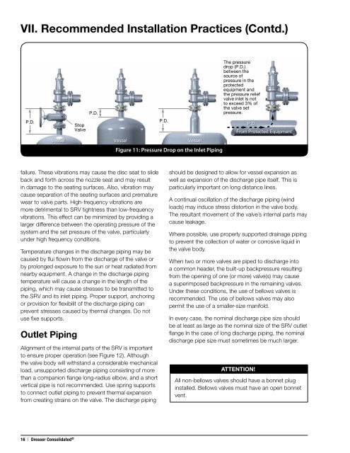
VII. Recommended Installation Practices (Contd.)P.D.StopValveP.D.P.D.Vessel Vessel VesselFigure 11: Pressure Drop on the Inlet PipingThe pressuredrop (P.D.)between thesource ofpressure in theprotectedequipment andthe pressure reliefvalve inlet is notto exceed 3% ofthe valve setpressure.P.D.From Protected Equipmentfailure. These vibrations may cause the disc seat to slideback and forth across the nozzle seat and may resultin damage to the seating surfaces. Also, vibration maycause separation of the seating surfaces and prematurewear to valve parts. High-frequency vibrations aremore detrimental to SRV tightness than low-frequencyvibrations. This effect can be minimized by providing alarger difference between the operating pressure of thesystem and the set pressure of the valve, particularlyunder high frequency conditions.Temperature changes in the discharge piping may becaused by flui flowin from the discharge of the valve orby prolonged exposure to the sun or heat radiated fromnearby equipment. A change in the discharge pipingtemperature will cause a change in the length of thepiping, which may cause stresses to be transmitted tothe SRV and its inlet piping. Proper support, anchoringor provision for flexibilit of the discharge piping canprevent stresses caused by thermal changes. Do notuse fixe supports.Outlet PipingAlignment of the internal parts of the SRV is importantto ensure proper operation (see Figure 12). Althoughthe valve body will withstand a considerable mechanicalload, unsupported discharge piping consisting of morethan a companion flange long-radius elbow, and a shortvertical pipe is not recommended. Use spring supportsto connect outlet piping to prevent thermal expansionfrom creating strains on the valve. The discharge pipingshould be designed to allow for vessel expansion aswell as expansion of the discharge pipe itself. This isparticularly important on long distance lines.A continual oscillation of the discharge piping (windloads) may induce stress distortion in the valve body.The resultant movement of the valve’s internal parts maycause leakage.Where possible, use properly supported drainage pipingto prevent the collection of water or corrosive liquid inthe valve body.When two or more valves are piped to discharge intoa common header, the built-up backpressure resultingfrom the opening of one (or more) valve(s) may causea superimposed backpressure in the remaining valves.Under these conditions, the use of bellows valves isrecommended. The use of bellows valves may alsopermit the use of a smaller-size manifold.In every case, the nominal discharge pipe size shouldbe at least as large as the nominal size of the SRV outletflange In the case of long discharge piping, the nominaldischarge pipe size must sometimes be much larger.ATTENTION!!All non-bellows valves should have a bonnet pluginstalled. Bellows valves must have an open bonnetvent.16 | Dresser Consolidated ®