1900 Series - Maintenance Manual
1900 Series - Maintenance Manual
1900 Series - Maintenance Manual

Create successful ePaper yourself
Turn your PDF publications into a flip-book with our unique Google optimized e-Paper software.
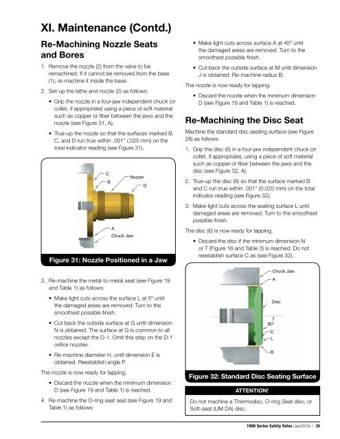
XI. <strong>Maintenance</strong> (Contd.)Re-Machining Nozzle Seatsand Bores1. Remove the nozzle (2) from the valve to beremachined. If it cannot be removed from the base(1), re-machine it inside the base.2. Set-up the lathe and nozzle (2) as follows:• Grip the nozzle in a four-jaw independent chuck (orcollet, if appropriate) using a piece of soft materialsuch as copper or fiber between the jaws and thenozzle (see Figure 31, A).• True-up the nozzle so that the surfaces marked B,C, and D run true within .001” (.025 mm) on thetotal indicator reading (see Figure 31).CBAChuck JawNozzleFigure 31: Nozzle Positioned in a JawD• Make light cuts across surface A at 45º untilthe damaged areas are removed. Turn to thesmoothest possible finish.• Cut back the outside surface at M until dimensionJ is obtained. Re-machine radius B.The nozzle is now ready for lapping.• Discard the nozzle when the minimum dimensionD (see Figure 19 and Table 1) is reached.Re-Machining the Disc SeatMachine the standard disc seating surface (see Figure28) as follows:1. Grip the disc (6) in a four-jaw independent chuck (orcollet, if appropriate), using a piece of soft materialsuch as copper or fiber between the jaws and thedisc (see Figure 32, A).2. True-up the disc (6) so that the surface marked Band C run true within .001" (0.025 mm) on the totalindicator reading (see Figure 32).3. Make light cuts across the seating surface L untildamaged areas are removed. Turn to the smoothestpossible finish.The disc (6) is now ready for lapping.• Discard the disc if the minimum dimension Nor T (Figure 16 and Table 3) is reached. Do notreestablish surface C as (see Figure 32).Chuck Jaw3. Re-machine the metal-to-metal seat (see Figure 19and Table 1) as follows:• Make light cuts across the surface L at 5º untilthe damaged areas are removed. Turn to thesmoothest possible finish.• Cut back the outside surface at G until dimensionN is obtained. The surface at G is common to allnozzles except the D-1. Omit this step on the D-1orifice nozzles.• Re-machine diameter H, until dimension E isobtained. Reestablish angle P.The nozzle is now ready for lapping.• Discard the nozzle when the minimum dimensionD (see Figure 19 and Table 1) is reached.4. Re-machine the O-ring seat seal (see Figure 19 andTable 1) as follows:ATTENTION!!90°CLDiscFigure 32: Standard Disc Seating SurfaceDo not machine a Thermodisc, O-ring Seat disc, orSoft-seat (UM DA) disc.BA<strong>1900</strong> <strong>Series</strong> Safety Valve (July/2010) | 35