1900 Series - Maintenance Manual
1900 Series - Maintenance Manual
1900 Series - Maintenance Manual

Create successful ePaper yourself
Turn your PDF publications into a flip-book with our unique Google optimized e-Paper software.
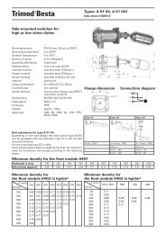
XVI . Conversion of <strong>1900</strong> <strong>Series</strong> Flanged SRVs (Contd.)Conversion from Bellows toConventional TypeConvert from a bellows to a conventional type valveas follows:1. Secure the eductor tube (40) in the base (1) byexpanding or swaging into the hole provided. Theupper end of the eductor tube should project abovethe guide surface of the base approximately .125˝(3.18 mm) and the lower end should point directlyand squarely toward the valve outlet. When the valveis assembled, the hole at the outer edge of the guideflange must fit loosely around the projection of theeductor tube.2. For F, G and H orifice valves only, machine the newlower spring washer (17) (see Figure 44 andTable 21).Machine toFit SpringFigure 44: Lower Spring WasherF, G, and H ValvesATTENTION!!For all <strong>1900</strong> <strong>Series</strong> SRVs, dimension A may notbe less than specified in Table 21.DEFATable 20: Machining Conventional to BellowsType Lower Spring WasherValve TypeBCin. mm in. mm1905F 1906F1910F 1912F1920F 1922F1905G 1906G.688 17.46 1.000 25.401910G 1912G1920G 1922G1914F 1916G1924F 1926F1914G 1916G .875 22.23 1.250 31.751918G 1924G1926G 1928G1918F 1928F 1.000 25.40 1.438 36.531905H1910H1920H1906H1922H.688 17.46 1.126 28.601912H 1924H .875 22.2 1.313 33.341914H1926H1916H 1.000 25.40 1.500 38.10Note: When indicated at surfaces D and E (see Figure 41), runout at surface F is not to exceed .005˝ (.127 mm) fullindicator reading.Table 21: Machining Bellows Type toConventional Lower Spring WasherValve TypeAin. mm1905-30F 1906-30F 1910-30F1920-30F 1922-30F 1905-30G1906-30G 1910-30G 1920-30G.250 6.351905-30H 1906-30H1912-30F 1922-30G1910-30H 1920-30H.313 7.941922-30H1914-30F 1916-30F 1924-30F1926-30F 1914-30G 1916-30G1918-30G 1924-30G 1926-30G.375 9.531928-30G 1912-30H 1924-30H1918-30F 1928-30F .438 11.111914-30H 1916-30H 1926-30H .500 12.70Note: When indicated at surfaces D and E (see Figure 46),run out at surface F is not to exceed .005˝ (.13 mm)full indicator reading.52 | Dresser Consolidated ®