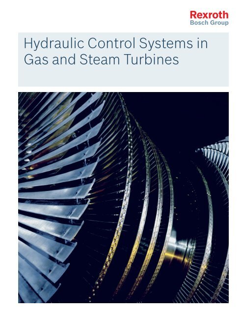
Hydraulic Control Systems in Gas and Steam ... - Bosch Rexroth
Hydraulic Control Systems in Gas and Steam ... - Bosch Rexroth
Hydraulic Control Systems in Gas and Steam ... - Bosch Rexroth

Create successful ePaper yourself
Turn your PDF publications into a flip-book with our unique Google optimized e-Paper software.
<strong>Hydraulic</strong> <strong>Control</strong> <strong>Systems</strong> <strong>in</strong><br />
<strong>Gas</strong> <strong>and</strong> <strong>Steam</strong> Turb<strong>in</strong>es
2 Industrial <strong>Hydraulic</strong>s | <strong>Systems</strong> & Eng<strong>in</strong>eer<strong>in</strong>g<br />
Always the Optimum Solution with<br />
<strong>Systems</strong> & Eng<strong>in</strong>eer<strong>in</strong>g from <strong>Rexroth</strong><br />
<strong>Rexroth</strong> has set up competence centers for virtually every<br />
application area of hydraulic drives <strong>and</strong> controls: <strong>Systems</strong> &<br />
Eng<strong>in</strong>eer<strong>in</strong>g. These <strong>in</strong>dustry-specifi c <strong>and</strong> specialist departments<br />
consist of a comb<strong>in</strong>ation of highly specialized eng<strong>in</strong>eers,<br />
project designers, <strong>and</strong> other experts. <strong>Rexroth</strong> customers<br />
are thus able to utilize the extensive application<br />
know-how of the world’s lead<strong>in</strong>g technology supplier.<br />
Application-focused system solutions are developed here to<br />
state-of-the-art technology—right through to turnkey systems.<br />
This means that customers are then able to concentrate<br />
on the core issues of their project design. <strong>Systems</strong> &<br />
Eng<strong>in</strong>eer<strong>in</strong>g produces the technical details, as it is the<br />
<strong>in</strong>tegration, <strong>in</strong> particular, of dem<strong>and</strong><strong>in</strong>g drive <strong>and</strong> control<br />
functions, that constitutes the success factors of customerspecifi<br />
c systems.<br />
This unique comb<strong>in</strong>ation of extensive application knowhow<br />
<strong>and</strong> reliable Drive & <strong>Control</strong> technology is maximized<br />
to the benefi t of the <strong>Rexroth</strong> customers. For this purpose<br />
<strong>Systems</strong> & Eng<strong>in</strong> eer<strong>in</strong>g is broken down <strong>in</strong>to four essential<br />
competencies:
Market <strong>and</strong> application competence<br />
<strong>Rexroth</strong> is able to offer extensive knowledge of the market<br />
with decades of experience <strong>in</strong> this branch <strong>and</strong> accurate<br />
knowledge of the dem<strong>and</strong>s <strong>and</strong> wishes of their customers.<br />
Eng<strong>in</strong>eer<strong>in</strong>g <strong>and</strong> project competence<br />
<strong>Rexroth</strong> meets all the necessary criteria to enable it to<br />
develop, simulate, <strong>and</strong> refi ne systems <strong>in</strong> an optimum way.<br />
In do<strong>in</strong>g so, we take <strong>in</strong>to account all relevant <strong>and</strong> <strong>in</strong>ter-<br />
nationally specifi c legal stipulations <strong>and</strong>, furthermore, also<br />
offer comprehensive risk, <strong>in</strong>surance, <strong>and</strong> site management.<br />
Technological competence<br />
With <strong>Rexroth</strong>, as with no other supplier worldwide, customers<br />
select from an extensive range of fi rst-class Drive &<br />
<strong>Control</strong> com ponents, such as cyl<strong>in</strong>ders, power units, valves,<br />
pumps, <strong>and</strong> control systems.<br />
International competence<br />
<strong>Rexroth</strong> has sales offi ces <strong>in</strong> over 80 countries, service<br />
centers <strong>in</strong> 37 countries, as well as 85 production locations<br />
around the world. This means that all products <strong>and</strong> services<br />
are available anywhere <strong>and</strong> at any time: <strong>in</strong> close proximity<br />
to the customer.<br />
www.boschrexroth-us.com<br />
<strong>Systems</strong> & Eng<strong>in</strong>eer<strong>in</strong>g | Industrial <strong>Hydraulic</strong>s<br />
Civil Eng<strong>in</strong>eer<strong>in</strong>g Technology<br />
Dredge Technology<br />
Energy Technology<br />
Enterta<strong>in</strong>ment Technology<br />
Materials H<strong>and</strong>l<strong>in</strong>g Technology<br />
Motion Technology<br />
Naval Technology<br />
Offshore Technology<br />
Research Technology<br />
Shiplift Technology<br />
Special Technology<br />
Stage Technology<br />
Test<strong>in</strong>g Technology<br />
Transport Technology<br />
Special Projects<br />
3
4 Industrial <strong>Hydraulic</strong>s | Installation<br />
All from One Source:<br />
<strong>Hydraulic</strong> <strong>Control</strong> <strong>Systems</strong> <strong>in</strong><br />
<strong>Gas</strong> <strong>and</strong> <strong>Steam</strong> Turb<strong>in</strong>es<br />
<strong>Hydraulic</strong> closed-loop control devices have a long tradition of use <strong>in</strong> turb<strong>in</strong>e construction<br />
<strong>and</strong> are certa<strong>in</strong>ly one of the “pioneers” of oil-hydraulic closed-loop control technology<br />
<strong>in</strong> general (e.g. centrifugal governors by J. Watt). Around 20 years ago, <strong>and</strong> with<br />
Siemens <strong>in</strong> particular, <strong>Rexroth</strong> started to replace the low-pressure closed-loop control<br />
concept, which had been used up to that po<strong>in</strong>t <strong>and</strong> was based on the bear<strong>in</strong>g lubrication<br />
system available, with a high-pressure concept. In turb<strong>in</strong>e manufacture the<br />
100–160 bar range is considered to be high pressure.<br />
The most important issues <strong>in</strong> this range are safety, availability,<br />
<strong>and</strong> life expectancy of the <strong>in</strong>stallations.<br />
<br />
<br />
Safety:<br />
Ensur<strong>in</strong>g that non-permissible operat<strong>in</strong>g conditions<br />
can be 100% controlled: If faults are not rectifi ed,<br />
this results <strong>in</strong> mach<strong>in</strong>e breakdown <strong>and</strong> potentially<br />
accidents <strong>and</strong> explosions may occur.<br />
Availability <strong>and</strong> life expectancy:<br />
Ensur<strong>in</strong>g that the generators can operate cont<strong>in</strong>uously:<br />
The most important issue with power stations is a non<strong>in</strong>terrupted<br />
power supply for maximum output. It must<br />
be guaranteed that the hydraulic components will last<br />
approx. 5 – 6 years without fail<strong>in</strong>g <strong>and</strong> caus<strong>in</strong>g a turbo<br />
assembly to break down.<br />
The application of hydraulic systems <strong>in</strong> gas <strong>and</strong> steam<br />
turb<strong>in</strong>es is expla<strong>in</strong>ed <strong>in</strong> greater detail <strong>in</strong> the follow<strong>in</strong>g<br />
description of turbo assemblies.<br />
In the course of development of power plant techno logy, an<br />
<strong>in</strong>creas<strong>in</strong>g number of so-called comb<strong>in</strong>ed cycle plants are<br />
built (comb<strong>in</strong>ed process of gas <strong>and</strong> steam turb<strong>in</strong>e). With<br />
the comb<strong>in</strong>ed cycle process, steam is generated with the<br />
hot waste gas from the gas turb<strong>in</strong>e by means of a wasteheat<br />
boiler, then be<strong>in</strong>g fed back to the power generation<br />
process via the downstream-connected steam turb<strong>in</strong>e. This<br />
process offers a degree of effi ciency of up to 60%.<br />
Both the control <strong>and</strong> the safety functions are met us<strong>in</strong>g<br />
<strong>Rexroth</strong> actuator technology.
Installation | Industrial <strong>Hydraulic</strong>s<br />
5
6 Industrial <strong>Hydraulic</strong>s | <strong>Hydraulic</strong> <strong>Control</strong> System<br />
<strong>Hydraulic</strong> <strong>Control</strong> System<br />
<strong>in</strong> <strong>Gas</strong> Turb<strong>in</strong>es<br />
A range of systems is required <strong>in</strong> the<br />
fuel circuit for master<strong>in</strong>g the closedloop<br />
con trol <strong>and</strong> safety functions of<br />
a gas turb<strong>in</strong>e. Basically, it is possible<br />
to equip the gas turb<strong>in</strong>e with two fuel<br />
systems, namely natural gas <strong>and</strong> fuel<br />
oil. Other fuels such as coal gas,<br />
synthesis gas, <strong>and</strong> naphtha can also<br />
be used.<br />
The layout of the gas turb<strong>in</strong>e will depend on the application.<br />
One relevant example of a fuel gas system is demonstrated<br />
<strong>in</strong> the diagram far right. As can be seen from the<br />
diagram, it is possible to operate the gas turb<strong>in</strong>e <strong>in</strong> pre-mix<br />
or diffusion mode. Us<strong>in</strong>g these modes requires application<br />
of the control <strong>and</strong> safety devices shown <strong>in</strong> the diagram.<br />
These devices consist of oil or gas valves, which are operated<br />
by hydraulic actuators from <strong>Rexroth</strong>.<br />
These components cover the complete power range of gas<br />
turb<strong>in</strong>es from around 25 MW to 340 MW.
<strong>Hydraulic</strong> <strong>Control</strong> System | Industrial <strong>Hydraulic</strong>s<br />
Fuel gas system for an annular combustion chamber<br />
Example of a diagram for a fuel gas system<br />
for an annular combustion chamber<br />
7
8 Industrial <strong>Hydraulic</strong>s | <strong>Hydraulic</strong> <strong>Control</strong> System<br />
<strong>Hydraulic</strong> <strong>Control</strong> System<br />
<strong>in</strong> <strong>Gas</strong> Turb<strong>in</strong>es<br />
The actuator can<br />
accommodate up to<br />
three positional<br />
transducers <strong>and</strong> six<br />
limit switches.<br />
All hydraulic cyl<strong>in</strong>ders are<br />
designed as low friction<br />
cyl<strong>in</strong>ders. The functional<br />
operation of the actuator<br />
is carried out <strong>in</strong> the cyl<strong>in</strong>der<br />
hous<strong>in</strong>g, which is designed<br />
as an <strong>in</strong>tegrated control<br />
block.
All fuel valves are kept open by hydraulic means aga<strong>in</strong>st a<br />
disc spr<strong>in</strong>g set arranged <strong>in</strong>side the cyl<strong>in</strong>der. The spr<strong>in</strong>g set<br />
closes the valves safely by mechanical means. The cyl<strong>in</strong>ders<br />
are designed as double-ended cyl<strong>in</strong>ders with double piston<br />
rods. As the oil volume is the same <strong>in</strong> both cyl<strong>in</strong>der chambers,<br />
the hydraulic oil can be led via the cyl<strong>in</strong>der hous<strong>in</strong>g<br />
directly to the rear side of the cyl<strong>in</strong>der dur<strong>in</strong>g the trip<br />
function (adjust<strong>in</strong>g time 120 – 300 ms). This design means<br />
that, for rapid switch<strong>in</strong>g movements, hydraulic oil does not<br />
need to be fed back to the power unit. As a result, the<br />
available pip<strong>in</strong>g is only required for “normal” control mode<br />
<strong>and</strong> therefore only needs to be designed for m<strong>in</strong>imal fl ows.<br />
With the exception of the servo valve, all hydraulic valves<br />
used are designed as leak-proof components. On the one<br />
h<strong>and</strong>, a high level of system security (safety cut-out) is<br />
guaranteed (all switch<strong>in</strong>g valves are seat valves); on the<br />
other h<strong>and</strong>, the leakage fl ow of the complete system is<br />
drastically reduced (e.g. if the trip actuators are completely<br />
leak-proof). The result is that, <strong>in</strong> many cases, a hydraulic<br />
power unit with only m<strong>in</strong>imal electric power will suffi ce for<br />
supply<strong>in</strong>g all the actuators.<br />
<strong>Hydraulic</strong> <strong>Control</strong> System | Industrial <strong>Hydraulic</strong>s<br />
As a special feature, all control valves can be fi tted with a superimposed trip<br />
function <strong>and</strong> the valves can match the seal<strong>in</strong>g re quirements of the trip valves.<br />
The pr<strong>in</strong>ciple of a redundant safety function is accomplished with a trip valve<br />
<strong>and</strong> a comb<strong>in</strong>ed trip-control valve. A second isolat<strong>in</strong>g valve is not applied. (e.g.<br />
with a control valve that is not leak-proof).<br />
9
10 Industrial <strong>Hydraulic</strong>s | <strong>Hydraulic</strong> <strong>Control</strong> System<br />
<strong>Hydraulic</strong> <strong>Control</strong> System<br />
<strong>in</strong> <strong>Steam</strong> Turb<strong>in</strong>es<br />
From its supply, the steam is fed to the HP-part of the<br />
turb<strong>in</strong>e via two <strong>in</strong>let valve comb<strong>in</strong>ations 1.1 <strong>and</strong> 1.2. After<br />
the <strong>in</strong>itial expansion, it is directed via <strong>in</strong>tercept valve comb<strong>in</strong>ations<br />
2.1 <strong>and</strong> 2.2 <strong>in</strong>to the IP-part. From the IP-part, the<br />
steam is led to the condenser via the LP-stages, from where<br />
it is fed back <strong>in</strong>to the process as feed water.<br />
For h<strong>and</strong>l<strong>in</strong>g <strong>in</strong>terruptions or faults, <strong>and</strong> for particular<br />
turb<strong>in</strong>e operat<strong>in</strong>g conditions, provision is made for<br />
HP-bypass station 4, IP-bypass station 5 <strong>and</strong> LP-bypass<br />
station 6. With the bypass stations it is possible to operate<br />
the steam supply <strong>in</strong>dependently of the turb<strong>in</strong>e.<br />
The valves <strong>in</strong>stalled for turb<strong>in</strong>e control are designed <strong>and</strong><br />
built by the turb<strong>in</strong>e manufacturer. The temperature range is<br />
up to 550 °C, with the pressure rang<strong>in</strong>g from 8 – 300 bar<br />
depend<strong>in</strong>g on the position of the valves <strong>in</strong> the <strong>in</strong>stallation.<br />
Each valve comb<strong>in</strong>ation consists of a trip valve <strong>and</strong> a con-
1 Ma<strong>in</strong> steam valve comb<strong>in</strong>ation<br />
2 Intercept valve comb<strong>in</strong>ation<br />
3 Butterfl y valve comb<strong>in</strong>ation<br />
4 HP – Bypass station<br />
5 IP – Bypass station<br />
6 LP – Bypass station<br />
<strong>Steam</strong> turb<strong>in</strong>e assembly<br />
Fig. 7 shows a typical layout of a steam turb<strong>in</strong>e<br />
assembly with the required steam valves<br />
<strong>Hydraulic</strong> <strong>Control</strong> System | Industrial <strong>Hydraulic</strong>s<br />
In contrast to a gas turb<strong>in</strong>e, the total thermal power of a steam turb<strong>in</strong>e has to be controlled<br />
by means of safety <strong>and</strong> control devices. With a gas turb<strong>in</strong>e the quantity of fuel fed is closedloop<br />
controlled (e.g. on a small scale comparable with the <strong>in</strong>jection pump on the diesel<br />
eng<strong>in</strong>e); on the steam turb<strong>in</strong>e, however, the complete steam fl ow has to be controlled by<br />
the steam valves. The steam valve nom<strong>in</strong>al diameters, the steam pressures, <strong>and</strong> temperatures<br />
on these components are many times higher than on the gas turb<strong>in</strong>e. This results <strong>in</strong> a<br />
considerably higher force requirement <strong>and</strong> thus greater diameters <strong>and</strong> spr<strong>in</strong>g forces of the<br />
hydraulic actuators used.<br />
trol valve. The safety <strong>and</strong> control functions are comb<strong>in</strong>ed <strong>in</strong><br />
a valve hous<strong>in</strong>g, onto which two hydraulic cyl<strong>in</strong>ders are<br />
mounted.<br />
<strong>Rexroth</strong> has a complete series of hydraulic cyl<strong>in</strong>ders with<br />
spr<strong>in</strong>g packs for use with various nom<strong>in</strong>al diameters <strong>and</strong><br />
pressure stages of these steam valves. The diameter can<br />
vary between 110 – 330 mm <strong>and</strong> the strokes range from<br />
50 – 250 mm.<br />
11
12 Industrial <strong>Hydraulic</strong>s | <strong>Hydraulic</strong> <strong>Control</strong> System<br />
<strong>Hydraulic</strong> <strong>Control</strong> System<br />
<strong>in</strong> <strong>Steam</strong> Turb<strong>in</strong>es
<strong>Hydraulic</strong> <strong>Control</strong> System | Industrial <strong>Hydraulic</strong>s<br />
As can be seen from the preced<strong>in</strong>g descriptions, <strong>Bosch</strong> <strong>Rexroth</strong> is <strong>in</strong> a position,<br />
via its modular system, to supply the complete hydraulic functions required <strong>in</strong><br />
gas <strong>and</strong> steam turb<strong>in</strong>es, the closed-loop control, <strong>and</strong> safety functions for the<br />
power range 25 – 1600 MW. A wide range of relevant reference projects,<br />
together with experience, are available <strong>and</strong> on h<strong>and</strong> if required.<br />
The complete actuator design is modular i.e. the diameter<br />
range is covered by three hous<strong>in</strong>g sizes <strong>and</strong> the spr<strong>in</strong>g<br />
forces by appropriate spr<strong>in</strong>g package sizes. As both cyl<strong>in</strong>der<br />
sizes <strong>and</strong> spr<strong>in</strong>g packs can vary, this series meets the<br />
requirements of steam valves for turb<strong>in</strong>e powers rang<strong>in</strong>g<br />
from 50 – 1600 MW.<br />
All necessary control functions are realized <strong>in</strong> a s<strong>in</strong>gle cyl<strong>in</strong>der<br />
hous<strong>in</strong>g, which is designed as an <strong>in</strong>tegral control block.<br />
Both cyl<strong>in</strong>der chambers are directly connected via the<br />
hous<strong>in</strong>g. The corrosion-proof spr<strong>in</strong>g packages ensure the<br />
system is closed <strong>and</strong> thus safe, once aga<strong>in</strong> purely by<br />
mechanical means (i.e. cut-off of the steam supply <strong>and</strong> thus<br />
that of the turb<strong>in</strong>e). The steam valves are kept open by<br />
hydraulic means aga<strong>in</strong>st the disc spr<strong>in</strong>gs, respective the<br />
steam control valves are position controlled via servo valves.<br />
Each valve comb<strong>in</strong>ation consists of a trip <strong>and</strong> a control<br />
part. Due to the steam cut-off already described, the control<br />
actuator is also equipped with a superimposed rapid<br />
clos<strong>in</strong>g feature.<br />
Here, too, as with the gas turb<strong>in</strong>e cyl<strong>in</strong>der, the high volume<br />
of oil occurr<strong>in</strong>g dur<strong>in</strong>g trip <strong>and</strong> short switch<strong>in</strong>g times is fed<br />
directly to the rear of the double-ended cyl<strong>in</strong>der.<br />
Accord<strong>in</strong>gly, the connections to the hydraulic power unit<br />
are only designed for closed-control operation, as no oil<br />
needs to be fed back to the power unit dur<strong>in</strong>g the trip<br />
function. Modular hydraulic power units, matched to the<br />
particular system <strong>and</strong> with the relevant performance data,<br />
are also available.<br />
13
14 Industrial <strong>Hydraulic</strong>s | Power Units<br />
<strong>Hydraulic</strong> <strong>Control</strong> System<br />
Power Units for<br />
<strong>Gas</strong> <strong>and</strong> <strong>Steam</strong> Turb<strong>in</strong>es<br />
Supply hydraulic pressure for control of fuel <strong>and</strong> gas<br />
valve actuators<br />
<strong>Steam</strong> turb<strong>in</strong>e safety <strong>and</strong> control systems<br />
Electronic control systems for the auxiliary functions for<br />
turb<strong>in</strong>es such as gas diverter control, turb<strong>in</strong>e starters,<br />
<strong>and</strong> steam bypass stations<br />
Redundant motor pump groups <strong>and</strong> valv<strong>in</strong>g for un<strong>in</strong>terrupted<br />
cont<strong>in</strong>uous safe operation<br />
Trip controls for fast shut down <strong>in</strong> the event the load on<br />
the turb<strong>in</strong>e is lost<br />
Low noise designs possible – 85 dB(A)<br />
Jack<strong>in</strong>g/lube oil supply<br />
<br />
Turb<strong>in</strong>e start<strong>in</strong>g
Power Unit Accessories<br />
Power Units | Industrial <strong>Hydraulic</strong>s<br />
All <strong>Rexroth</strong> sites worldwide operate <strong>in</strong> accordance with the same st<strong>and</strong>ards. This<br />
guarantees a supply of spare parts at every production site worldwide.<br />
<strong>Rexroth</strong> has a worldwide unique range of spare parts for<br />
power units – such as fl anges, screw fi tt<strong>in</strong>gs, measur<strong>in</strong>g<br />
<strong>and</strong> display devices, fi lters etc.<br />
15<br />
There are group-own production sites, subsidiaries, country<br />
units, sales offi ces <strong>and</strong> service centers <strong>in</strong> over 80 countries<br />
around the world. You can be assured that your power units<br />
are be<strong>in</strong>g ma<strong>in</strong>ta<strong>in</strong>ed throughout their complete service life<br />
– <strong>and</strong> beyond: from <strong>in</strong>stallation <strong>and</strong> ma<strong>in</strong>tenance right<br />
through to modifi cations <strong>and</strong> modernization.
16 Industrial <strong>Hydraulic</strong>s | Accessories<br />
Blocks, Plates, …<br />
Multifunctional System<br />
Components<br />
Whether check, pressure control, fl ow control functions,<br />
comb<strong>in</strong>ed pressure-check functions, or rapid traverse <strong>and</strong><br />
creep functions—<strong>Rexroth</strong> offers ready-to-<strong>in</strong>stall hydraulic<br />
control plates <strong>in</strong> modular design for your power unit. This<br />
modular solution offers a high level of variability, even <strong>in</strong><br />
comb<strong>in</strong>ation with complex functions. Segments with branch<br />
or customer-specifi c circuits can also easily be <strong>in</strong>tegrated.<br />
St<strong>and</strong>ard or Special Designs<br />
In cooperation with the customer <strong>Rexroth</strong> development<br />
eng<strong>in</strong>eers transform the required functions <strong>in</strong>to a detailed<br />
<strong>and</strong> optimally matched hydraulic schematic. Us<strong>in</strong>g <strong>in</strong>-house<br />
developed simulation programs all process steps are tested<br />
<strong>and</strong> matched under dynamic load<strong>in</strong>g conditions, <strong>and</strong> then<br />
comb<strong>in</strong>ed to form logical functional units.<br />
Manifold Assemblies for Power Generation <strong>in</strong>clude:<br />
Safety trip modules<br />
<br />
Turn<strong>in</strong>g gear blocks
Quality Determ<strong>in</strong>es the Function<br />
Experienced design eng<strong>in</strong>eers, production specialists, <strong>and</strong><br />
assembly workers guarantee smooth functional operation of<br />
the subassembly. Not only all of the components, but also<br />
the complete subassemblies are tested once more before<br />
dispatch <strong>and</strong> <strong>in</strong>stallation.<br />
Accessories | Industrial <strong>Hydraulic</strong>s<br />
17
18 Industrial <strong>Hydraulic</strong>s | Service<br />
Service Competence –<br />
World-wide<br />
<strong>Rexroth</strong> Service offers world-wide<br />
professionally coord<strong>in</strong>ated services<br />
on the highest level. All services are<br />
available to the same st<strong>and</strong>ard all<br />
around the world.
Intelligent<br />
<strong>Hydraulic</strong>s <strong>in</strong><br />
New Dimensions<br />
Whether it’s a case of<br />
rais<strong>in</strong>g or lower<strong>in</strong>g loads<br />
smoothly, undertak<strong>in</strong>g l<strong>in</strong>ear<br />
or rotational movements,<br />
achiev<strong>in</strong>g even acceleration<br />
or accurate position<strong>in</strong>g,<br />
ma<strong>in</strong>ta<strong>in</strong><strong>in</strong>g preset speeds,<br />
transmitt<strong>in</strong>g power or<br />
l<strong>in</strong>k<strong>in</strong>g motion sequences—<br />
<strong>in</strong> fact, wherever economical<br />
power is required, this<br />
is where hydraulics comes<br />
<strong>in</strong>to its own.<br />
<strong>Rexroth</strong> is the technology<br />
<strong>and</strong> market leader <strong>in</strong> <strong>in</strong>dustrial<br />
hydraulics with an<br />
extensive product program<br />
<strong>and</strong> proven applications<br />
know-how. With the widest<br />
selection of hydraulic products<br />
<strong>in</strong> the world, <strong>Rexroth</strong><br />
will provide you with st<strong>and</strong>ard<br />
products, applicationorientated<br />
systems, <strong>and</strong><br />
customized solutions of the<br />
highest quality. Furthermore,<br />
with the aid of the<br />
latest micro electronics,<br />
<strong>Rexroth</strong> has made hydraulics<br />
even more powerful<br />
than ever.<br />
<strong>Rexroth</strong> is the ideal partner<br />
if you want to develop<br />
highly effi cient mach<strong>in</strong>es<br />
<strong>and</strong> production facilities—<br />
from the fi rst po<strong>in</strong>t of contact<br />
right through to commission<strong>in</strong>g<br />
<strong>and</strong> across the<br />
complete life cycle. Teams<br />
operat<strong>in</strong>g worldwide will<br />
take on the complete project<br />
design work of your<br />
systems, even produc<strong>in</strong>g a<br />
turnkey solution, if required.<br />
Whether it’s competent<br />
support on the telephone,<br />
urgent repairs or supply of<br />
spare parts, or a callout<br />
by one of our eng<strong>in</strong>eers—<br />
whichever service you<br />
require, experienced personnel<br />
<strong>and</strong> a worldwide<br />
service network will guarantee<br />
that the problem is<br />
swiftly solved.<br />
Us<strong>in</strong>g hydraulic drive <strong>and</strong><br />
control technology from<br />
<strong>Rexroth</strong> will help you<br />
become more competitive<br />
than ever.<br />
Intelligent <strong>Hydraulic</strong>s | Industrial <strong>Hydraulic</strong>s<br />
Effi cient <strong>Hydraulic</strong>s<br />
Paired with MultitechnologyCompetence<br />
Intelligent hydraulics <strong>in</strong> new dimensions:<br />
As lead<strong>in</strong>g supplier <strong>in</strong> <strong>in</strong>dustrial<br />
hydraulics, <strong>Rexroth</strong> takes an outst<strong>and</strong><strong>in</strong>g<br />
position with components, systems,<br />
dist<strong>in</strong>ct application know-how,<br />
<strong>and</strong> high eng<strong>in</strong>eer<strong>in</strong>g competence.<br />
With <strong>Rexroth</strong>, you can choose from the world’s largest<br />
product range of application-related systems <strong>and</strong> customized<br />
special solutions of high quality. In conjunction with<br />
advanced microelectronics, <strong>Rexroth</strong> has made hydraulics<br />
even more effi cient. The products can be easily <strong>in</strong>tegrated<br />
<strong>in</strong>to modern mach<strong>in</strong>e concepts, are extremely powerful <strong>and</strong><br />
feature high energetic effi ciency. Be<strong>in</strong>g a supplier for all<br />
technologies, <strong>Rexroth</strong> always offers the ideal applicationspecifi<br />
c drive solution. <strong>Rexroth</strong> is your ideal development<br />
partner for highly effi cient mach<strong>in</strong>ery <strong>and</strong> production facilities—from<br />
the fi rst contact through to commission<strong>in</strong>g <strong>and</strong><br />
over the entire life cycle. Teams who are active all around<br />
the world assume the complete eng<strong>in</strong>eer<strong>in</strong>g of your plant<br />
<strong>and</strong> mach<strong>in</strong>ery, if requested, until maturity for series production<br />
or turnkey h<strong>and</strong>over. With multi-technological<br />
competence <strong>and</strong> the use of drive <strong>and</strong> control technology<br />
from <strong>Rexroth</strong> you will be more competitive than ever.<br />
19
<strong>Bosch</strong> <strong>Rexroth</strong> Corporation<br />
<strong>Hydraulic</strong>s<br />
2315 City L<strong>in</strong>e Road<br />
Bethlehem, PA 18017-2131<br />
Telephone (610) 694-8300<br />
Facsimile (610) 694-8467<br />
www.boschrexroth-us.com<br />
Power Gen 2010 – Brochure<br />
© <strong>Bosch</strong> <strong>Rexroth</strong> Corporation 2010 Pr<strong>in</strong>ted <strong>in</strong> the United States