MAINTENANCE MANUAL - Meritor
MAINTENANCE MANUAL - Meritor
MAINTENANCE MANUAL - Meritor
You also want an ePaper? Increase the reach of your titles
YUMPU automatically turns print PDFs into web optimized ePapers that Google loves.
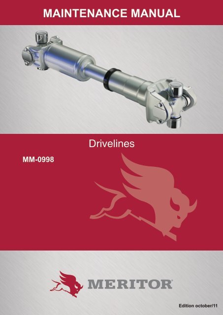
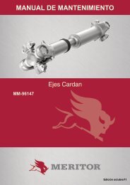
<strong>MAINTENANCE</strong> <strong>MANUAL</strong><br />
MM-0998<br />
Drivelines<br />
Edition october/11
Index<br />
1 - Drivelines............................................................................................................. 03<br />
2 - Introduction.......................................................................................................... 05<br />
3 - Removal and Disassembly.................................................................................. 06<br />
4 - Assembly and Installation.................................................................................... 08<br />
5 - Lubrication........................................................................................................... 11<br />
<strong>MAINTENANCE</strong> <strong>MANUAL</strong>
Service Notes<br />
About This Manual<br />
This manual provides service and repair procedures<br />
for <strong>Meritor</strong><br />
Xtended Lube MXL 17N, 176N and 18N Series<br />
drivelines.<br />
Before You Begin<br />
1. Read and understand all instructions and procedures<br />
before you begin to service components.<br />
2. Read and observe all Warning and Caution<br />
hazard alert messages in this publication.<br />
They provide information that can help prevent<br />
serious personal injury, damage to components,<br />
or both.<br />
3. Follow your company’s maintenance and service,<br />
installation, and diagnostics guidelines.<br />
4. Use special tools when required to help avoid<br />
serious personal injury and damage to components.<br />
How to Obtain Additional Maintenance<br />
and Service Information for<br />
<strong>Meritor</strong> MXL 17N, 176N and 18N<br />
Series Easy Service and Full-<br />
-Round Drivelines<br />
Refer to Maintenance Manual MM-96147, Drivelines;<br />
and Maintenance Manual 1, Preventive<br />
Maintenance and Lubrication. To obtain these<br />
publications, visit Literature on Demand at<br />
arvinmeritor.com.<br />
Hazard Alert Messages and Torque<br />
Symbols<br />
WARNING<br />
A Warning alerts you to an instruction or procedure<br />
that you must follow exactly to avoid<br />
serious personal injury and damage to components.<br />
CAUTION<br />
A Caution alerts you to an instruction or procedure<br />
that you must follow exactly to avoid damage<br />
to components.<br />
This symbol alerts you to tighten fasteners<br />
to a specified torque value.<br />
Information contained in this publication was in effect at the time<br />
the publication was approved for printing and is subject to change<br />
without notice or liability. <strong>Meritor</strong> Heavy Vehicle Systems, LLC,<br />
reserves the right to revise the information presented or to discontinue<br />
the production of parts described at any time.<br />
2 <strong>MAINTENANCE</strong> <strong>MANUAL</strong>
Drivelines<br />
Components<br />
TYPICAL DRIVELINE SYSTEM<br />
NOTE: Series shown are for illustration only.<br />
TRANSMISSION<br />
NON-SLIPCOU-<br />
PLINGSHAFTAS-<br />
SEMBLY<br />
STANDARD<br />
SLIP ASSEMBLY<br />
END YOKEOUTPUT<br />
WELD<br />
YOKE<br />
TUBING BEARING<br />
STUB<br />
CENTER<br />
BEARING<br />
KIT<br />
SPLINED<br />
YOKE<br />
SLIP<br />
YOKE SEAL<br />
STEEL<br />
SHROUD<br />
SPLINE<br />
PLUG<br />
TUBING<br />
WELD<br />
YOKE<br />
WELCH PLUG<br />
<strong>MAINTENANCE</strong> <strong>MANUAL</strong><br />
3
Drivelines<br />
TYPICAL DRIVELINE SYSTEM<br />
NOTE: Series shown are for illustration only.<br />
Figure 1.2<br />
SHORT COUPLE-<br />
DSLIP ASSEMBLY<br />
END<br />
YOKE<br />
INPUT<br />
FRONT<br />
AXLE<br />
END<br />
YOKE<br />
OUTPUT SLIP<br />
YOKE<br />
SEAL<br />
SHAFT<br />
YOKE<br />
END YOKE<br />
INPUT<br />
REAR<br />
AXLE<br />
UNIVERSAL JOINT COMPONENTS<br />
YOKE<br />
BEARING<br />
CUP<br />
CAPSCREWS<br />
4 <strong>MAINTENANCE</strong> <strong>MANUAL</strong>
Introduction<br />
Description<br />
<strong>Meritor</strong> Xtended Lube MXL 17N, 176N<br />
and 18N Series Drivelines<br />
The <strong>Meritor</strong> Xtended Lube MXL 17N, 176N<br />
and 18N Series drivelines have extended lubrication<br />
intervals for both the slip sections and<br />
universal joints at 100,000 miles (160 000 km)<br />
for linehaul applications.<br />
How to Identify an Xtended Lube MXL<br />
Series Driveline<br />
• The slip yoke seal includes a protective steel<br />
shroud to improve sealing and retain seals<br />
securely in place. Figure 2.1.<br />
• The universal joint cover plates are stamped<br />
“MXL.” Figure 2.1.<br />
EASY SERVICETM (1/2 ROUND)<br />
Figure 2.3<br />
STEEL<br />
SHROUD<br />
MXL<br />
MXL<br />
STAMP<br />
MXL<br />
<strong>Meritor</strong> Xtended Lube MXL Series<br />
Figure 2.1<br />
<strong>Meritor</strong> Full-Round and Easy Service<br />
(Greaseable)<br />
The Full-Round, Figure 2.2, and Easy Service,<br />
Figure 2.3, greaseable drivelines require<br />
periodic lubrication of the universal joints and<br />
slip yoke splines.<br />
FULL-ROUND<br />
Figure 2.2<br />
<strong>MAINTENANCE</strong> <strong>MANUAL</strong><br />
5
Removal and Disassembly<br />
Hazard Alert Messages<br />
Read and observe all Warning and Caution hazard<br />
alert messages in this publication. They<br />
provide information that can help prevent serious<br />
personal injury, damage to components,<br />
or both.<br />
4. Remove the second bearing cup. Figure 3.2.<br />
WARNING<br />
To prevent serious eye injury, always wear<br />
safe eye protection when you perform vehicle<br />
maintenance or service. Park the vehicle on a<br />
level surface. Block the wheels to prevent the<br />
vehicle from moving. Support the vehicle with<br />
safety stands. Do not work under a vehicle supported<br />
only by jacks. Jacks can slip and fall<br />
over. Serious personal injury and damage to<br />
components can result.<br />
Removal<br />
Driveline<br />
1. Park the vehicle on a level surface. Block the<br />
wheels to keep the vehicle from moving. Raise<br />
the vehicle so that the area you will service<br />
is off the ground. Support the vehicle with<br />
safety stands.<br />
2. Loosen and remove the capscrews from the<br />
end yoke bearing cups.<br />
3. Remove the first bearing cup. If necessary,<br />
use a bearing puller to remove the bearing<br />
cup from the yoke bore. Figure 3.1.<br />
UNIVERSAL<br />
JOINT PULLER<br />
TIGER TOOL<br />
NUMBER 10102<br />
BUSHING<br />
4001893a<br />
Figure 3.1<br />
Figure 3.2<br />
NOTE:<br />
Support the driveline when you remove it<br />
from the end yoke.<br />
5. Slide the yoke to one side until you can work<br />
a trunnion free from the yoke bore.<br />
6. Slide the yoke in the OPPOSITE direction<br />
while removing the universal joint from the<br />
end yoke.<br />
7. Repeat Step 2 to Step 6 to separate the slip<br />
yoke end of the driveline.<br />
Universal Joint<br />
1. Loosen and remove the capscrews from the<br />
two remaining bearing cups on the yoke end<br />
of the driveline.<br />
2. Remove the bearing cups. If necessary, use<br />
a commercial bearing puller to remove the<br />
bearing cups from the yoke bores.<br />
3. Work the trunnions free of the yoke bores.<br />
Remove the universal joint cross from the<br />
weld yoke.<br />
4. Repeat Step 1 to Step 3 to remove the universal<br />
joint cross from the slip yoke.<br />
Disassembly<br />
Slip Yoke<br />
WARNING<br />
4001839a<br />
Use a brass or synthetic mallet for assembly<br />
and disassembly procedures. Do not hit steel<br />
parts with a steel hammer. Pieces of a part can<br />
break off. Serious personal injury and damage<br />
to components can result.<br />
6 <strong>MAINTENANCE</strong> <strong>MANUAL</strong>
Removal and Disassembly<br />
1. Use a brass or copper hammer and a drift to<br />
tap the shroud off the slip seal. Be careful not<br />
to damage the shroud. Figure 3.3.<br />
4. Pull the slip yoke and slip shaft sections<br />
apart. Figure 3.6.<br />
HAMMER<br />
DRIFT<br />
MXL<br />
MXL<br />
MXL<br />
4007590a<br />
4007587a<br />
Figure 3.3<br />
2. Use a screwdriver to pry the seal out of the<br />
groove in the slip yoke. Figure 3.4.<br />
Figure 3.6<br />
5. Remove the seal. Figure 3.7. Remove the<br />
shroud. Figure 3.8.<br />
MXL<br />
4007588a<br />
Figure 3.4<br />
3. Mark the slip yoke and slip shaft sections to<br />
ensure that you reassemble them into their<br />
original positions. Figure 3.5.<br />
4001823a<br />
Figure 3.7<br />
MXL<br />
MXL<br />
MXL<br />
MXL<br />
4007589a<br />
4001824a<br />
Figure 3.5<br />
Figure 3.8<br />
<strong>MAINTENANCE</strong> <strong>MANUAL</strong><br />
7
Assembly and Installation<br />
Hazard Alert Messages<br />
Read and observe all Warning and Caution hazard<br />
alert messages in this publication. They<br />
provide information that can help prevent serious<br />
personal injury, damage to components,<br />
or both.<br />
SMALL<br />
DIAMETER<br />
LARGE<br />
DIAMETER<br />
WARNING<br />
SHROUD<br />
To prevent serious eye injury, always wear<br />
safe eye protection when you perform vehicle<br />
maintenance or service. Park the vehicle on a<br />
level surface. Block the wheels to prevent the<br />
vehicle from moving. Support the vehicle with<br />
safety stands. Do not work under a vehicle supported<br />
only by jacks. Jacks can slip and fall<br />
over. Serious personal injury and damage to<br />
components can result.<br />
4001829a<br />
Figure 4.2<br />
3. Align the slip yoke and spline shaft sections<br />
with the phasing marks you made on these<br />
sections during disassembly. Figure 4.3.<br />
Assembly<br />
MXL<br />
Slip Yoke<br />
1. Install the new shroud. Figure 4.1.<br />
PHASING MARKS<br />
MXL<br />
4007591a<br />
Figure 4.3<br />
4. Install the spline shaft into the slip yoke until<br />
the splines fully engage. Figure 4.3.<br />
5. Snap the seal into the groove. Figure 4.4.<br />
4001828a<br />
Figure 4.1<br />
2. Install the new seal onto the spline shaft<br />
neck. Ensure that the seal is installed with<br />
the SMALL diameter side facing DOWN for<br />
correct installation. Figure 4.2.<br />
MXL<br />
4007592a<br />
Figure 4.4<br />
8 <strong>MAINTENANCE</strong> <strong>MANUAL</strong>
Assembly and Installation<br />
6. Verify that the seal has been correctly installed<br />
on the slip yoke by rotating the seal.<br />
When the seal is installed correctly, the seal<br />
will rotate easily.<br />
• If the seal does not rotate easily: Remove the<br />
seal and reinstall it.<br />
7. Install the steel shroud over the seal by hand.<br />
Figure 4.5.<br />
• If it appears that a mallet is needed to install<br />
the shroud: It is likely the seal has not been<br />
installed correctly.Repeat Step 6.<br />
Figure 4.5<br />
MXL<br />
4007593a<br />
Installation<br />
Universal Joint<br />
WARNING<br />
Use a brass or synthetic mallet for assembly<br />
and disassembly procedures. Do not hit steel<br />
parts with a steel hammer. Pieces of a part can<br />
break off. Serious personal injury and damage<br />
to components can result.<br />
1. Install the universal joint cross into the yoke.<br />
2. Install the two bearing cups through the yoke<br />
bores and onto the universal joint cross trunnions.<br />
If necessary, use a copper or brass<br />
hammer to tap the bearing caps until they are<br />
fully seated.<br />
3. Hand-tighten the capscrews through the bearing<br />
cover plate and into the slip yoke.<br />
4. Use a torque wrench to alternately tighten the<br />
capscrews to the correct specifications. Refer<br />
to Table A.<br />
5. Repeat Step 1 to Step 3 to install the universal<br />
joint cross into the weld yoke.<br />
Figure 4.5<br />
8. Push together the driveline sections. Figure<br />
4.6.<br />
Driveline<br />
1. Wipe off the end yoke bearing bores. Insert<br />
the trunnion through the yoke bore.<br />
2. Check the bearing cup to ensure that the needle<br />
bearings are in place. Replace the bearing<br />
cup when the needle bearings are missing<br />
or out of place.<br />
3. Hold the cross. Use a copper or brass hammer<br />
to lightly tap the bearing cup completely<br />
into the yoke bore. Figure 4.7.<br />
MXL<br />
MXL<br />
4007595a<br />
Figure 4.6<br />
4001840a<br />
Figure 4.7<br />
<strong>MAINTENANCE</strong> <strong>MANUAL</strong><br />
9
Assembly and Installation<br />
4. Align the cover plate holes and the yoke ear.<br />
Figure 4.8. Install the bearing cover plate<br />
flush against the milled surface of the yoke.<br />
Table A: Torque Specifications — Full-<br />
-Round<br />
Driveline<br />
Series<br />
“A”<br />
Inches<br />
(mm)<br />
Thread<br />
Size<br />
Inches<br />
Torque<br />
Specs lb-ft<br />
(Nm)<br />
16N<br />
5.31<br />
(134.87)<br />
5/16-24<br />
26-35<br />
(35-47)<br />
CAPSCREWS<br />
4001841a<br />
17N<br />
6.09<br />
(154.69)<br />
3/8-24<br />
38-48<br />
(51-65)<br />
Figure 4.8<br />
176N<br />
7.00<br />
(177.8)<br />
3/8-24<br />
38-48<br />
(51-65)<br />
5. Install new capscrews and hand-tighten them<br />
through the bearing cover plate and into the<br />
yoke.<br />
18N<br />
7.55<br />
(191.77)<br />
3/8-24<br />
38-48<br />
(51-65)<br />
6. Repeat Step 2 to Step 5 to install the second<br />
bearing cup.<br />
• If the cover plate will not seat flush against<br />
the yoke surface: Remove each bearing cup<br />
from the yoke bore. Check the bottom of each<br />
bearing cup. If you find a needle bearing, replace<br />
the bearing cup.<br />
7. Use a torque wrench to alternately tighten the<br />
capscrews to correct specifications. Refer to<br />
Table A. Figure 4.9.<br />
“A”<br />
YOKE GAUGE<br />
TOOL<br />
Identifies driveline<br />
series<br />
“A” dimension<br />
across yoke ears<br />
determines end<br />
yoke/universal<br />
joint series.<br />
4001848a<br />
4001842a<br />
Figure 4.9<br />
10 <strong>MAINTENANCE</strong> <strong>MANUAL</strong>
Lubrication<br />
Hazard Alert Messages.<br />
Read and observe all Warning and Caution hazard<br />
alert messages in this publication. They<br />
provide information that can help prevent serious<br />
personal injury, damage to components,<br />
or both.<br />
WARNING<br />
To prevent serious eye injury, always wear<br />
safe eye protection when you perform vehicle<br />
maintenance or service. Park the vehicle on a<br />
level surface. Block the wheels to prevent the<br />
vehicle from moving. Support the vehicle with<br />
safety stands. Do not work under a vehicle supported<br />
only by jacks. Jacks can slip and fall<br />
over. Serious personal injury and damage to<br />
components can result.<br />
Universal Joint<br />
After installation into the end yokes, lubricate<br />
the universal joints at the grease fitting until<br />
grease flows from the bearing cup seals on all<br />
four trunnions. Use <strong>Meritor</strong> grease specification<br />
O-634-B, NLGI Grade 2 with EP additive. Figure<br />
5.1.<br />
• If grease does not purge from the seals:<br />
Follow the steps below.<br />
New grease mustflow<br />
at all four seals.<br />
4001844a<br />
Figure 5.2<br />
2. Loosen the bearing cup capscrews. Add grease<br />
until grease purges from the seals.<br />
• If grease still does not purge from all four<br />
trunnion seals: Remove the universal joint<br />
and correct the problem.<br />
• If you cannot determine the problem: Replace<br />
the universal joint.<br />
3. Tighten the capscrews. Refer to Table A.<br />
Slip Yoke Splines<br />
NOTE:<br />
To ensure correct and adequate lubrication<br />
of the splines, the slip assembly should be<br />
fully collapsed or nearly fully collapsed before<br />
applying grease.<br />
Add <strong>Meritor</strong> specification O-634-B, NLGI Grade<br />
2 with EP additive to the slip yoke grease<br />
fitting as shown in Figure 5.3.<br />
Shown without end<br />
yokes for clarity.<br />
4001843a<br />
Figure 5.1<br />
4001846a<br />
1. Move the assembly UP-AND-DOWN or SI-<br />
DE-TO-SIDE while you apply grease gun<br />
pressure. Figure 5.2.<br />
Figure 5.3<br />
<strong>MAINTENANCE</strong> <strong>MANUAL</strong><br />
11
Lubrication<br />
The amount of grease will vary with the driveline<br />
series. To avoid purging excess grease through<br />
the slip yoke welch plug when the assembly is<br />
fully collapsed, follow the recommendations in<br />
Table B.<br />
Table B<br />
* Xtended Lube MXL Series drivelines are<br />
identifiable from RN drivelines in the following<br />
two ways. (1) The slip yoke seal includes a protective<br />
steel shroud. (2) The universal joint cover<br />
plates are stamped with MXL.<br />
<strong>Meritor</strong> RPL25/20 Series drivelines are permanently<br />
lubricated. No greasing is required.<br />
Driveline<br />
Series<br />
Grease Volume<br />
Number of<br />
Pumps<br />
Table D: Approved Lubricants<br />
17N 0.7 oz (20 grams) 4-6<br />
176N 0.7 oz (20 grams) 4-6<br />
18N 1.1 oz (30 grams) 6-8<br />
For Removal, Installation and Lubrication<br />
Procedures for <strong>Meritor</strong> Easy Service<br />
and Full-Round 17N, 176N and 18N<br />
Series Drivelines<br />
Refer to Maintenance Manual MM-96147, Drivelines.<br />
To obtain this publication, refer to the<br />
Service Notes page on the front inside cover of<br />
this manual.<br />
Lubrication Intervals for <strong>Meritor</strong> Easy<br />
Service and Full-Round RN Series<br />
and Xtended Lube MXL Series Drivelines<br />
Table C: Lubrication Intervals<br />
Lubricant<br />
Universal Joint<br />
Grease<br />
Recommendation<br />
Must meet <strong>Meritor</strong> Specification<br />
O-634-B<br />
(NLGI Grade 2, Lithium<br />
12-Hydroxy Stearate with<br />
Molybdenum Disulfide)<br />
Amalie All Purpose Grease<br />
with<br />
Moly-L1-2M<br />
Exxon 5160<br />
Shell Super Duty Special FF<br />
Marathon Maralube Molycode<br />
529<br />
Phillips Petroleum Philube<br />
MW-EP2 Grease<br />
Shell Moly Poly Grease<br />
Kendall L424 Grease<br />
Amoco Super Chassis Grease<br />
Ford Specification M1C-75B<br />
or part<br />
number PN-C1AZ 19590<br />
Application MXL* 17N-18N RN 155N-18N<br />
City<br />
On Highway<br />
Linehaul<br />
25,000 miles<br />
(40 000 km) or 6<br />
months<br />
100,000 miles<br />
(160 000 km)<br />
100,000 miles<br />
(160 000 km)<br />
6,500 miles<br />
(10 400 km)<br />
16,000 miles<br />
(25 000 km)<br />
50,000 miles<br />
(80 000 km)<br />
Construction<br />
The greasing interval depends on<br />
the individual conditions, speed<br />
and loads. To determine the<br />
interval, inspect for the presence<br />
of grease at all positions until an<br />
interval can be determined. Grease<br />
the assembly as necessary.<br />
12 <strong>MAINTENANCE</strong> <strong>MANUAL</strong>
<strong>MAINTENANCE</strong> <strong>MANUAL</strong><br />
Always use Technical Manuals of...
Always use original parts<br />
For more details, see the Spare Parts Catalog<br />
Customer service<br />
55 11 3684.6741<br />
55 11 3684.6867<br />
Purchase the CD-ROM failure analysis of components of the axis<br />
traction<br />
Customer Service<br />
Av. João Batista, 825 - Osasco - SP - 06097-105<br />
Tel. (11) 3684-664 - (11) 3684-6867<br />
AfterMarket (Replace parts)<br />
R. Ester Rombenso, 403 - Osasco - SP - 06097-120<br />
Tel. (11) 0800-555530<br />
www.arvinmeritor.com


