

Installation Instructions - Sloan Valve Company
Installation Instructions - Sloan Valve Company
Installation Instructions - Sloan Valve Company

Create successful ePaper yourself
Turn your PDF publications into a flip-book with our unique Google optimized e-Paper software.
Code No. 0816546<br />
Rev. 2 (08/11)<br />
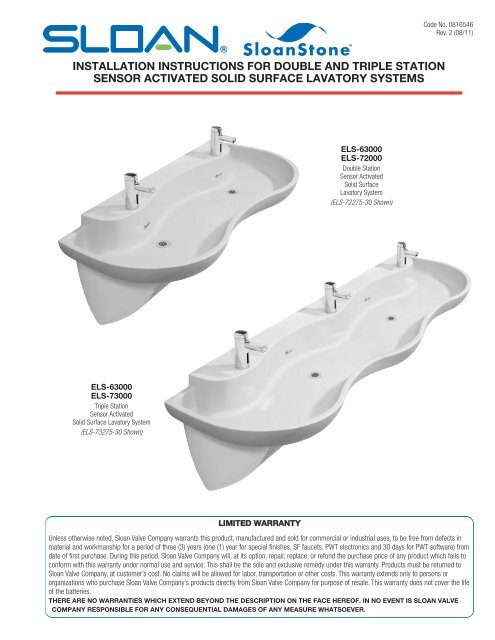
INSTALLATION INSTRUCTIONS FOR DOUBLE AND TRIPLE STATION<br />
SENSOR ACTIVATED SOLID SURFACE LAVATORY SYSTEMS<br />
ELS-63000<br />
ELS-72000<br />
Double Station<br />
Sensor Activated<br />
Solid Surface<br />
Lavatory System<br />
(ELS-72275-30 Shown)<br />
ELS-63000<br />
ELS-73000<br />
Triple Station<br />
Sensor Activated<br />
Solid Surface Lavatory System<br />
(ELS-73275-30 Shown)<br />
LIMITED WARRANTY<br />
Unless otherwise noted, <strong>Sloan</strong> <strong>Valve</strong> <strong>Company</strong> warrants this product, manufactured and sold for commercial or industrial uses, to be free from defects in<br />
material and workmanship for a period of three (3) years (one (1) year for special finishes, SF faucets, PWT electronics and 30 days for PWT software) from<br />
date of first purchase. During this period, <strong>Sloan</strong> <strong>Valve</strong> <strong>Company</strong> will, at its option, repair, replace, or refund the purchase price of any product which fails to<br />
conform with this warranty under normal use and service. This shall be the sole and exclusive remedy under this warranty. Products must be returned to<br />
<strong>Sloan</strong> <strong>Valve</strong> <strong>Company</strong>, at customer’s cost. No claims will be allowed for labor, transportation or other costs. This warranty extends only to persons or<br />
organizations who purchase <strong>Sloan</strong> <strong>Valve</strong> <strong>Company</strong>’s products directly from <strong>Sloan</strong> <strong>Valve</strong> <strong>Company</strong> for purpose of resale. This warranty does not cover the life<br />
of the batteries.<br />
THERE ARE NO WARRANTIES WHICH EXTEND BEYOND THE DESCRIPTION ON THE FACE HEREOF. IN NO EVENT IS SLOAN VALVE<br />
COMPANY RESPONSIBLE FOR ANY CONSEQUENTIAL DAMAGES OF ANY MEASURE WHATSOEVER.
ROUGH-IN (FAUCETS MAY VARY)<br />
FOR MODELS:<br />
ELS-62000<br />
ELS-72000<br />
Double Station Lavatory System<br />
Lavatory System Weight (Packaged):<br />
Approximately 88 Lbs (40 Kg)<br />
54”<br />
(1372 mm)<br />
30”<br />
(762 mm)<br />
FOR MODELS:<br />
ELS-63000<br />
ELS-73000<br />
Triple Station Lavatory System<br />
Lavatory System Weight (Packaged):<br />
Approximately 130 Lbs/59 Kg<br />
26”<br />
(660 mm)<br />
26”<br />
(660 mm)<br />
76”<br />
(2134 mm)<br />
LIVE TEXT<br />
1 13 /16” (46 mm)<br />
VARIABLE MOUNTING HEIGHT CHART<br />
DIMENSION T.A.S. T.A.S. A.D.A.<br />
DESCRIPTION AGES 4-10 AGES 11-15 STANDARD<br />
A ROUGH-IN 20-1/2” (521 mm) 22-1/2” (572 mm) 24” (610 mm)<br />
B RECOMMENDED RIM HEIGHT 29-7/8” (759 mm) 31-7/8” (810 mm) 33 (838 mm)<br />
C FLOOR CLEARANCE 10-7/8” (276 mm) 12-7/8” (327 mm) 14” (356 mm)<br />
D NOMINAL FRAME HEIGHT ‡ 25-1/8” (638 mm) 27-1/8 (689 mm) 28-1/4” (718 mm)<br />
‡ Refer to Step 3.<br />
2
PRIOR TO INSTALLATION<br />
Prior to installing the <strong>Sloan</strong> Optima ELS-60000/ELS-70000 Series<br />
Lavatory System, install the items listed below. Also, refer to the<br />
appropriate rough-in diagram on Page 2 and 3.<br />
• Electrical receptacle(s) – 120 VAC, 2 amp service for plug-in faucets<br />
and soap dispensers. The ELS-73000-xx-MSD 3-station sink with<br />
hardwire soap dispensers in conjunction with hardwire faucets<br />
require TWO electrical outlets (see rough-in on Page 2), all others<br />
require ONE.<br />
• Hot and cold water supply lines or tempered water supply line (If<br />
there is no tempered water supply, install thermostatic mixing valve<br />
between hot and cold water supply)<br />
• Drain lines<br />
IMPORTANT:<br />
• ADEQUATE STRUCTURAL SUPPORT IN OR BEHIND THE<br />
WALL IS REQUIRED. REFER TO THE APPROPRIATE<br />
ROUGH-IN DIAGRAM ON PAGE 2 FOR DRY WEIGHT OF<br />
SINK. STRUCTURAL SUPPORT MUST HAVE A MINIMUM<br />
PULLOUT RATING OF 1000 POUNDS (450 Kg) FOR EACH<br />
FASTENER.<br />
• ALL PLUMBING SHOULD BE INSTALLED IN<br />
ACCORDANCE WITH APPLICABLE CODES AND<br />
REGULATIONS.<br />
• BEFORE CONNECTING SUPPLY LINES TO SUPPLY<br />
STOPS, FLUSH ALL WATER LINES UNTIL WATER IS<br />
CLEAR.<br />
WHEN INSTALLING HARDWIRED FAUCETS AND<br />
SOAP DISPENSERS:<br />
• ALL ELECTRICAL WIRING SHOULD BE INSTALLED IN<br />
ACCORDANCE WITH NATIONAL/LOCAL CODES AND<br />
REGULATIONS.<br />
• A 24 VAC STEP-DOWN TRANSFORMER MUST BE USED<br />
FOR HARDWIRE FAUCETS(S) AND 6 VAC PLUG-IN<br />
ADAPTER FOR SOAP DISPENSER(S).<br />
• USE APPROPRIATE PRECAUTIONS WHILE<br />
CONNECTING TRANSFORMER TO 120 VAC POWER<br />
SOURCE.<br />
• DO NOT PLUG TRANSFORMER INTO POWER SOURCE<br />
(RECEPTACLE) UNTIL ALL WIRING IS COMPLETED.<br />
PERMANENT DAMAGE TO THE TRANSFORMER AND<br />
CIRCUIT CONTROL MODULE WILL RESULT IF 24 VAC<br />
WIRES TOUCH EACH OTHER OR SHORT WHEN POWER<br />
SUPPLY IS ACTIVE.<br />
TOOLS REQUIRED FOR INSTALLATION<br />
• Electric drill for drilling anchor holes.<br />
• Standard sockets and open end wrench set for installing anchoring<br />
fasteners and connecting water lines.<br />
• Open end wrench for connecting water lines.<br />
• Pipe wrench for installing drain lines.<br />
• Phillips and straight blade screwdrivers.<br />
SINK LOCATION<br />
Determine the appropriate wall location for the Lavatory System. Consider that hot and cold water supply lines, drain lines, and an electrical source<br />
(receptacle or wiring depending on type of transformer used when installing hardwire faucets and soap dispensers) will be required. Compare the<br />
physical dimensions of the Lavatory System to the space available for the installation. If wall is not load bearing, a carrier may be required behind the<br />
wall. Refer to the appropriate Rough-in diagram on Page 2 and 3 for Lavatory System dimensions.<br />
Prior to Lavatory System installation, electric wiring (when installing hardwire faucets and soap dispensers), water supply and drain must be installed.<br />
1 – INSTALL THERMOSTATIC MIXING VALVE<br />
A<br />
If there is no tempered water supply, install Thermostatic Mixing<br />
<strong>Valve</strong> between hot and cold water supply.
2 – MOUNTING WALL BRACKETS<br />
Double Station<br />
1/4”-20 x 1/2”<br />
TRUSS HEAD<br />
1/4”-20 SCREWS x 1/2” (6)<br />
TRUSS HEAD<br />
SCREWS (6)<br />
1/4”-20 x 1/2” Truss Head Screw<br />
(Actual Size)<br />
Triple Station<br />
DISTANCE BETWEEN<br />
BRACKETS<br />
DISTANCE BETWEEN<br />
BRACKETS<br />
1/4”-20 x 1/2”<br />
TRUSS HEAD<br />
1/4”-20 SCREWS x 1/2” (6)<br />
TRUSS HEAD<br />
SCREWS (6)<br />
A Attach brackets to basin using 1/4”-20 x 1/2”<br />
truss head screws.<br />
B<br />
Measure distance between brackets. Make<br />
sure the carrier (when needed) can<br />
accommodate the proper location for the<br />
brackets.<br />
C<br />
D<br />
DISTANCE BETWEEN<br />
BRACKETS<br />
DISTANCE BETWEEN<br />
BRACKETS<br />
Determine the appropriate location for the holes to secure the brackets to the wall. Use the following dimensions as a reference.<br />
Mount basin and brackets to wall using fasteners with waster that hold over 1000 lbf (pounds-force) withdrawal load each.<br />
NOTE: IF DESIRED, DETACH BRACKETS FROM BASIN AND MOUNT BRACKETS TO WALL FIRST. THEN<br />
MOUNT BASIN TO BRACKETS USING 1/4”-20 X 1/2” TRUSS HEAD SCREWS. GRID STRAINER MAY BE IN-<br />
STALLED PRIOR TO ATTACHING BASIN TO BRACKETS. REFER TO STEP 6.<br />
Double Station<br />
2-1/2” 1-1/4”<br />
(64 mm) (32 mm)<br />
2-1/2” 1-1/4”<br />
(64 mm) (32 mm)<br />
7-1/2”<br />
(191 mm)<br />
“F”<br />
7-1/2”<br />
SEE TABLE<br />
(191<br />
ON<br />
mm)<br />
PAGE “F” 2<br />
SEE TABLE ON<br />
PAGE 2<br />
DISTANCE BETWEEN<br />
BRACKETS<br />
DISTANCE BETWEEN<br />
BRACKETS<br />
FINISHED FLOOR<br />
FINISHED FLOOR<br />
2-1/2”<br />
Triple Station<br />
(64 mm)<br />
2-1/2”<br />
(64 mm)<br />
7-1/2”<br />
(191 mm)<br />
“F”<br />
7-1/2”<br />
SEE TABLE<br />
(191<br />
ON<br />
mm)<br />
PAGE “F” 2<br />
SEE TABLE ON<br />
PAGE 2<br />
1-1/4”<br />
(32 mm)<br />
1-1/4”<br />
(32 mm)<br />
DISTANCE BETWEEN<br />
BRACKETS<br />
DISTANCE DISTANCE BETWEEN DISTANCE<br />
BETWEEN BRACKETS BETWEEN<br />
BRACKETS DISTANCE - STEP 2B<br />
BRACKETS DISTANCE - STEP 2B<br />
BETWEEN<br />
BETWEEN<br />
BRACKETS - STEP 2B<br />
BRACKETS - STEP 2B<br />
FINISHED FLOOR<br />
FINISHED FLOOR
3 – REMOVE END CAPS FROM FRAME<br />
A Loosen (do not remove) screws on inside of frame. C For triple station sinks,<br />
remove the Front Panel<br />
Support.<br />
B<br />
Remove both End<br />
Caps by removing<br />
the two outer<br />
screws on each Cap.<br />
Slide Cap forward in<br />
slot and pull it out<br />
through enlarged<br />
hole in Frame.<br />
Bottom Backside of Frame<br />
Front Panel Support<br />
Front of Frame<br />
Enlarged Hole and<br />
Slot in Frame<br />
End Cap (2)<br />
4 – MOUNT FRAME TO WALL (FOR ELS-70000 SERIES)<br />
A If desired, apply adhesive to back surfaces of Frame. B Mount Frame to wall using 3/8" fasteners with 1000 lb min<br />
pull out strength in the following locations:<br />
1. Each hole in the extreme outer corners of top support<br />
2. One of either of the two holes in the top position of each<br />
upright<br />
3. The lower hole location in each upright<br />
Fasteners may be optionally applied to any of the remaining<br />
mounting hole locations.<br />
Level Frame in both directions before tightening fasteners<br />
Double Station<br />
securely. Triple Station<br />
D<br />
(See VARIABLE<br />
MOUNTING<br />
HEIGHT CHART<br />
On Page 2)<br />
FINISHED FLOOR<br />
C<br />
For triple station sinks, reinstall the Front Panel<br />
Support.<br />
D<br />
For installations including the optional SJS-1650 Soap Dispenser,<br />
refer to Soap Dispenser <strong>Installation</strong> <strong>Instructions</strong>.<br />
Front Panel Support<br />
5
5 – MOUNT BASIN TO FRAME (FOR ELS-70000 SERIES)<br />
Note: If desired, Grid Strainers, Faucets and Soap<br />
Dispensers may be installed prior to mounting Basin to the<br />
Frame. Refer to Steps 5 and 6.<br />
1/4”-20 x 1/2” Pan Head Screw (SEMS)<br />
(Actual Size)<br />
A Mount Basin to Frame using 1/4”-20 x 1/2” SEMS fasteners. B If desired, apply caulk between Basin and wall.<br />
Double Station<br />
Triple Station<br />
6 – INSTALL GRID STRAINERS AND CONNECT DRAIN LINE<br />
A<br />
Install Grid Strainers.<br />
Grid Strainer<br />
B<br />
Plumb drain outlets to wall.<br />
Drain Line<br />
7 – INSTALL FAUCETS AND SOAP DISPENSERS<br />
Install Faucets and Soap Dispensers as instructed in the installation MORE FAUCET OPTIONS<br />
instructions furnished with the Faucets and Soap Dispensers. Also see<br />
Step 7 for Transformer hookup.<br />
SOAP DISPENSER OPTIONS<br />
EAF-100/150<br />
EAF-275<br />
EAF-200/250<br />
EAF-225<br />
ETF-610/EBF-615<br />
SJS-1650<br />
FAUCET OPTIONS<br />
ESD-350<br />
EFX-3 SERIES<br />
EFX-6 SERIES<br />
ETF-80/EBF-85<br />
SF-2100/SF-2150 SF-2200/SF-2250 SF-2300/SF-2350<br />
ETF-600/EBF-650<br />
EFX-2 SERIES<br />
EBF-187<br />
6
8 – CONNECT FAUCET POWER CABLES TO TRANSFORMER AND PLUG TRANSFORMER<br />
INTO RECEPTACLE<br />
A<br />
Connect one Power Cable from each Control Module to a Twist<br />
On Terminal. Connect second Power Cable from each Control<br />
Module to a second Twist On Terminal.<br />
Control Modules<br />
B<br />
Connect terminals to<br />
transformer.<br />
Transformer<br />
Twist On<br />
Terminals<br />
C<br />
Plug Transformer into outlet.<br />
Faucet Power Cables<br />
Twist On Terminals<br />
9 – CONNECT SUPPLY LINE TO THERMOSTATIC MIXING VALVE<br />
A<br />
Install water Supply Line.<br />
10 – TURN ON WATER SUPPLY, CHECK FOR WATER LEAKS AND INSTALL END CAPS<br />
A<br />
B<br />
Turn on water supply.<br />
Check all plumbing for water leaks.<br />
Double Station Sink Shown<br />
C<br />
Replace End Caps. Insert the screw located on the inside of the<br />
Cap into the enlarged hole of the Frame. Then slide the Cap into<br />
place. Loosely install the two front screws. Slide End Cap UP to<br />
eliminate any gap between the End Cap and Basin. Tighten the<br />
inside screw securely. Lastly, tighten the two front screws<br />
securely. Follow the same procedure for the second End Cap.<br />
END CAP<br />
7
11 – INSTALL FRONT PANEL(S) – FOR ELS-70000 SERIES ONLY<br />
A<br />
Replace Front Panel by hanging top lip of Panel into track of<br />
Trim Rail under Basin. Swing panel into position and affix with 2<br />
Fasteners. For triple station sinks, repeat this procedure for<br />
second panel.<br />
Double Station<br />
Triple Station<br />
Front Panel (2)<br />
Fastener (2)<br />
Front Panel Fastener (2)<br />
12 – INSTALL COVER CABINET – FOR ELS-60000 SERIES ONLY<br />
NOTE: ENSURE THAT THERE ARE NO GAPS BETWEEN<br />
THE BASIN AND CABINET, AND THE CABINET AND WALL.<br />
A Replace cover and screws and tighten firmly in place with t-<br />
handled wrench.<br />
B<br />
Install plastic cabinet by fastening it to the wall via screws<br />
through cabinet’s mounting eyelets. Double-station (6) fasteners<br />
and triple-station (8) fasteners.<br />
Prior to fastening the triple-station cabinet to the wall, bring the<br />
cabinet to the basin and press the front of the cabinet to the<br />
basin ensuring that the velcro straps, pre-applied to the basin<br />
and cabinet, meet and attach firmly. Allow the cabinet to hang<br />
from the basin, while fastening the cabinet to the wall.<br />
P-TRAPS (2)<br />
(NOT INCLUDED)<br />
VELCRO<br />
STRAPS<br />
PLASTIC<br />
CABINET<br />
INSIDE<br />
CABINET<br />
MOUNTING<br />
EYELETS (6)<br />
PLASTIC<br />
CABINET<br />
MOUNTING<br />
EYELETS (8)<br />
P-TRAPS (2)<br />
(NOT INCLUDED)<br />
8
OPTIONAL – SOAP DISPENSER PUMP MOUNTING INSTRUCTIONS<br />
A<br />
FOR ELS-70000<br />
SERIES ONLY – Install<br />
Soap Dispenser Pump (SJS-<br />
1650 for battery powered<br />
applications and SJS-1750<br />
for hardwire applications) at<br />
the location(s) shown. Mount<br />
Soap Dispenser as instructed<br />
in the <strong>Installation</strong> <strong>Instructions</strong><br />
furnished with the Soap<br />
Dispenser using spacers and<br />
extended length screws<br />
provided.<br />
FRONT VIEW — DOUBLE STATION SINK<br />
SIDE VIEW<br />
DOUBLE AND TRIPLE<br />
STATION SINKS<br />
FRONT VIEW — TRIPLE STATION SINK<br />
SLOANSTONE® CARE AND MAINTENANCE<br />
<strong>Sloan</strong>Stone ® surfaces may be easily cleaned using a conventional cleaning agent such as an ammonia based liquid cleaner (glass cleaner). Cover<br />
faucet(s) and, if applicable, soap dispenser(s) to protect the finish. DO NOT USE the same cloth that was used to wipe down <strong>Sloan</strong>Stone surface as<br />
the faucet(s) and, if applicable, soap dispenser(s).<br />
Dry stains on a matte finish can be removed with a 3M Scotch-Brite scouring pad or a mild abrasive cleaner.<br />
Burns or scorches can be removed by sanding with the Light Duty Buffing Pad (included with <strong>Sloan</strong>Stone sinks). Follow sanding with the General<br />
Purpose Buffing Pad (included with <strong>Sloan</strong>Stone sinks) to match finish of sanding area to surrounding area. A final buffing may be required on polished<br />
surfaces. Accidental nicks or chips can be repaired with a special patch kit available in all <strong>Sloan</strong>Stone colors, contact <strong>Sloan</strong> 1-888-SLOAN-14<br />
(1-888-756-2614) or your <strong>Sloan</strong> Representative, if needed.<br />
Avoid exposing <strong>Sloan</strong>Stone surfaces to strong chemicals such as acetones, paint removers/thinners and sulfuric acid, or hydrochloric chemical<br />
cleaners. Exposure to strong chemicals may result in permanent damage to <strong>Sloan</strong>Stone surfaces.<br />
REFER TO FAUCET OR SOAP DISPENSER INSTALLATION INSTRUCTIONS<br />
SHEET FOR TROUBLESHOOTING AND OPERATION INSTRUCTIONS
PARTS LIST<br />
ELS-62000 Double Station Cabinet and Basin Assemblies<br />
1<br />
2<br />
4<br />
5<br />
3<br />
6<br />
ItemPart Description<br />
No. No.<br />
1 SEE TABLE Double Station Lavatory Basin Assembly<br />
2 ELC-41 Screw, Machine Truss Head 1/4-20 (6)<br />
3 EW-122 Mounting Bracket (4)<br />
ItemPart Description<br />
No. No.<br />
4 EW-127 Velcro Strip (Hook)<br />
5 ETF-725-A Grid Strainer Assembly (2)<br />
6 EW-105 Plastic Cabinet for Double Station Lavatory<br />
– EW-98 Light Duty Buffing Pad (Not Shown)<br />
– EW-108 General Duty Buffing Pad (Not Shown)<br />
ITEM NO. 1 — Double Station Lavatory Basin Hole Patterns<br />
Hole Pattern — A B C D<br />
Part No. ELS-9-A-XXX ELS-9-A-XXX-A ELS-12-A-XXX-B ELS-12-A-XXX-C ELS-12-A-XXX-D<br />
Basin Hole Pattern
PARTS LIST<br />
ELS-63000 Triple Station Cabinet and Basin Assemblies<br />
1<br />
2<br />
4<br />
5<br />
3<br />
6<br />
ItemPart Description<br />
No. No.<br />
1 SEE TABLE Triple Station Lavatory Basin Assembly<br />
2 ELC-41 Screw, Machine Truss Head 1/4-20 (6)<br />
3 EW-122 Mounting Bracket (4)<br />
ItemPart Description<br />
No. No.<br />
4 EW-127 Velcro Strip (Hook)<br />
5 ETF-725-A Grid Strainer Assembly (2)<br />
6 EW-123 Plastic Cabinet for Triple Station Lavatory<br />
– EW-98 Light Duty Buffing Pad (Not Shown)<br />
– EW-108 General Duty Buffing Pad (Not Shown)<br />
ITEM NO. 1 — Triple Station Lavatory Basin Hole Patterns<br />
Hole Pattern — A B C D<br />
Part No. ELS-11-A-XXX ELS-11-A-XXX-A ELS-11-A-XXX-B ELS-11-A-XXX-C ELS-11-A-XXX-D<br />
Basin Hole<br />
Pattern
PARTS LIST<br />
ELS-72000 Double Station Cabinet and Basin Assemblies<br />
8<br />
5<br />
9<br />
11<br />
10<br />
4<br />
2<br />
7<br />
6<br />
3<br />
ItemPart Description<br />
No. No.<br />
1 EW-20-A Cabinet Weldment, 2 Station<br />
2 EW-99 U-Type Nut Standard 1/4-20 Thread (6)<br />
3 EW-60 End Cap Right - Machined<br />
4 EW-52 End Cap Left - Machined<br />
5 EW-15 Screw, Pan Head 1/4-20 x 1/2” Long (SEMS) (2)<br />
6 EW-16 Screw, Pan Head 1/4-20 x 1” Long (SEMS) (4)<br />
7 EW-25 Front Panel, 2 Station<br />
ItemPart Description<br />
No. No.<br />
8 SEE TABLE Double Station Lavatory Basin Assembly<br />
9 ETF-725-A Grid Strainer Assembly (2)<br />
10 EW-15 Screw, Pan Head 1/4-20 x 1/2” Long (SEMS) (6)<br />
11 EW-61 Overflow Cover Plate (2)<br />
– EW-98 Light Duty Buffing Pad (Not Shown)<br />
– EW-108 General Duty Buffing Pad (Not Shown)<br />
ITEM NO. 8 — Double Station Lavatory Basin Hole Patterns<br />
Hole Pattern — A B C D<br />
Part No. ELS-9-A-XXX ELS-9-A-XXX-A ELS-12-A-XXX-B ELS-12-A-XXX-C ELS-12-A-XXX-D<br />
Basin Hole Pattern<br />
12
PARTS LIST<br />
ELS-73000 Triple Station Cabinet and Basin Assemblies<br />
10<br />
6<br />
13<br />
11<br />
4<br />
8<br />
12<br />
9<br />
ItemPart Description<br />
No. No.<br />
1 EW-149 Cabinet Weldment, 3 Station<br />
2 EW-50 Front Panel Support - Machined<br />
3 EW-36 Screw, Pan Head #8-32 x 7/16” Long (SEMS) (2)<br />
4 EW-99 U-type Nut, Standard 1/4-20 Thread (8)<br />
5 EW-60 End Cap Right - Machined<br />
6 EW-52 End Cap Left - Machined<br />
7 EW-16 Screw, Pan Head 1/4-20 x 1” Long (SEMS) (4)<br />
2<br />
5<br />
3<br />
1<br />
7<br />
ItemPart Description<br />
No. No.<br />
8 EW-15 Screw, Pan Head 1/4-20 x 1/2” Long (SEMS) (2)<br />
9 EW-155 Front Panel, 3 Station (2)<br />
10 SEE TABLE Triple Station Lavatory Basin Assembly<br />
11 ETF-725-A Grid Strainer Assembly (2)<br />
12 EW-15 Screw, Pan Head 1/4-20 x 1/2” Long (SEMS) (8)<br />
13 EW-61 Overflow Cover Plate (2)<br />
– EW-98 Light Duty Buffing Pad (Not Shown)<br />
– EW-108 General Duty Buffing Pad (Not Shown)<br />
ITEM NO. 10 — Triple Station Lavatory Basin Hole Patterns<br />
Hole Pattern — A B C D<br />
Part No. ELS-11-A-XXX ELS-11-A-XXX-A ELS-11-A-XXX-B ELS-11-A-XXX-C ELS-11-A-XXX-D<br />
Basin Hole<br />
Pattern<br />
When assistance is required, please contact <strong>Sloan</strong> Tech Support at:<br />
1-888-SLOAN-14 (1-888-756-2614)<br />
The information contained in this document is subject to change without notice.<br />
SLOAN COMPANY • 10500 SEYMOUR AVENUE • FRANKLIN PARK, IL 60131<br />
Phone: 1-800-982-5839 or 1-847-671-4300 • Fax: 1-800-447-8329 or 1-847-671-4380 • www.sloanvalve.com<br />
Copyright © 2011 SLOAN VALVE COMPANY Code No. 0816546 – Rev. 2 (08/11)


