

SloanStone EW-40000 Series - Sloan Valve Company
SloanStone EW-40000 Series - Sloan Valve Company
SloanStone EW-40000 Series - Sloan Valve Company

Create successful ePaper yourself
Turn your PDF publications into a flip-book with our unique Google optimized e-Paper software.
<strong>EW</strong>-<strong>40000</strong> <strong>Series</strong> I.I. — Rev. 0 (02/03)<br />
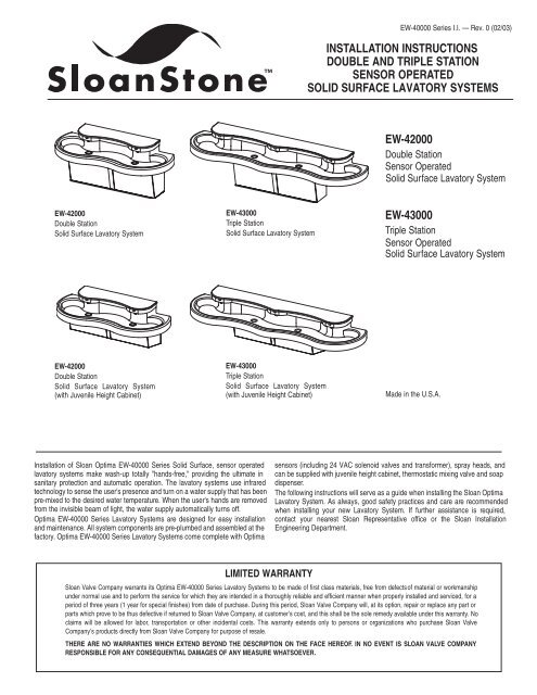
INSTALLATION INSTRUCTIONS<br />
DOUBLE AND TRIPLE STATION<br />
SENSOR OPERATED<br />
SOLID SURFACE LAVATORY SYSTEMS<br />
<strong>EW</strong>-42000<br />
Double Station<br />
Sensor Operated<br />
Solid Surface Lavatory System<br />
<strong>EW</strong>-42000<br />
Double Station<br />
Solid Surface Lavatory System<br />
<strong>EW</strong>-43000<br />
Triple Station<br />
Solid Surface Lavatory System<br />
<strong>EW</strong>-43000<br />
Triple Station<br />
Sensor Operated<br />
Solid Surface Lavatory System<br />
<strong>EW</strong>-42000<br />
Double Station<br />
Solid Surface Lavatory System<br />
(with Juvenile Height Cabinet)<br />
<strong>EW</strong>-43000<br />
Triple Station<br />
Solid Surface Lavatory System<br />
(with Juvenile Height Cabinet)<br />
Made in the U.S.A.<br />
Installation of <strong>Sloan</strong> Optima <strong>EW</strong>-<strong>40000</strong> <strong>Series</strong> Solid Surface, sensor operated<br />
lavatory systems make wash-up totally "hands-free," providing the ultimate in<br />
sanitary protection and automatic operation. The lavatory systems use infrared<br />
technology to sense the user's presence and turn on a water supply that has been<br />
pre-mixed to the desired water temperature. When the user's hands are removed<br />
from the invisible beam of light, the water supply automatically turns off.<br />
Optima <strong>EW</strong>-<strong>40000</strong> <strong>Series</strong> Lavatory Systems are designed for easy installation<br />
and maintenance. All system components are pre-plumbed and assembled at the<br />
factory. Optima <strong>EW</strong>-<strong>40000</strong> <strong>Series</strong> Lavatory Systems come complete with Optima<br />
sensors (including 24 VAC solenoid valves and transformer), spray heads, and<br />
can be supplied with juvenile height cabinet, thermostatic mixing valve and soap<br />
dispenser.<br />
The following instructions will serve as a guide when installing the <strong>Sloan</strong> Optima<br />
Lavatory System. As always, good safety practices and care are recommended<br />
when installing your new Lavatory System. If further assistance is required,<br />
contact your nearest <strong>Sloan</strong> Representative office or the <strong>Sloan</strong> Installation<br />
Engineering Department.<br />
LIMITED WARRANTY<br />
<strong>Sloan</strong> <strong>Valve</strong> <strong>Company</strong> warrants its Optima <strong>EW</strong>-<strong>40000</strong> <strong>Series</strong> Lavatory Systems to be made of first class materials, free from defects of material or workmanship<br />
under normal use and to perform the service for which they are intended in a thoroughly reliable and efficient manner when properly installed and serviced, for a<br />
period of three years (1 year for special finishes) from date of purchase. During this period, <strong>Sloan</strong> <strong>Valve</strong> <strong>Company</strong> will, at its option, repair or replace any part or<br />
parts which prove to be thus defective if returned to <strong>Sloan</strong> <strong>Valve</strong> <strong>Company</strong>, at customer’s cost, and this shall be the sole remedy available under this warranty. No<br />
claims will be allowed for labor, transportation or other incidental costs. This warranty extends only to persons or organizations who purchase <strong>Sloan</strong> <strong>Valve</strong><br />
<strong>Company</strong>’s products directly from <strong>Sloan</strong> <strong>Valve</strong> <strong>Company</strong> for purpose of resale.<br />
THERE ARE NO WARRANTIES WHICH EXTEND BEYOND THE DESCRIPTION ON THE FACE HEREOF. IN NO EVENT IS SLOAN VALVE COMPANY<br />
RESPONSIBLE FOR ANY CONSEQUENTIAL DAMAGES OF ANY MEASURE WHATSOEVER.
LAVATORY SYSTEM ROUGH-IN<br />
Double Station Lavatory System<br />
MODEL <strong>EW</strong>-42000 — 0.5 gpm (1.9 Lpm) Max. — Aerator<br />
LAVATORY SYSTEM WEIGHT (Empty) — 190 Lbs. (86 Kg)<br />
Standard Height Cabinet<br />
Juvenile Height Cabinet<br />
Triple Station Lavatory System<br />
MODEL <strong>EW</strong>-43000 — 0.5 gpm (1.9 Lpm) Max. — Aerator<br />
LAVATORY SYSTEM WEIGHT (Empty) — 250 Lbs. (113 Kg)<br />
Standard Height Cabinet<br />
Juvenile Height Cabinet<br />
VARIABLE MOUNTING HEIGHT CHART<br />
DIMENSION Texas Accessibility Texas Accessibility American Disability<br />
DESCRIPTION Standard (T.A.S.) Standard (T.A.S.) Act (A.D.A.)<br />
AGES 4-10 AGES 11-15 STANDARD<br />
A ROUGH-IN 20½” (521 mm) 22½” (572 mm) 24” (610 mm)<br />
B KNEE CLEARANCE 26” (660 mm) 28” (711 mm) 29½ (749 mm)<br />
C RIM HEIGHT 30” (762 mm) 32” (813 mm) 33½” (851 mm)<br />
D TOE CLEARANCE 13½” (343 mm) 15½” (394 mm) 17” (432 mm)<br />
2
PRIOR TO INSTALLATION<br />
Prior to installing the <strong>Sloan</strong> Optima <strong>EW</strong>-<strong>40000</strong> <strong>Series</strong> Lavatory System, install the<br />
items listed below. Also, refer to the appropriate rough-in diagram on Page 2.<br />
• When Using Plug-In Transformer — Install electrical receptacle(s) for plug-in<br />
transformer(s) — 120 VAC, 2 amp service for each ETF-233 (24 VAC, 35 VA)<br />
plug-in transformer used.<br />
• When Using Box Mount Transformer — Install electrical wiring to the transformer<br />
location — 120 VAC, 2 amp service for each standard EL-248-40 (24 VAC, 40 VA)<br />
or EL-154 (24 VAC, 50 VA) transformer used.<br />
• Hot and cold water supply lines or tempered water supply line<br />
• Drain lines<br />
Important:<br />
• ADEQUATE STRUCTURAL SUPPORT IN OR BEHIND THE WALL IS REQUIRED.<br />
REFER TO THE APPROPRIATE ROUGH-IN DIAGRAM ON PAGE 2 FOR DRY WEIGHT<br />
OF SINK. STRUCTURAL SUPPORT MUST HAVE A MINIMUM PULLOUT RATING OF<br />
1000 POUNDS (450 Kg).<br />
• ALL ELECTRICAL WIRING SHOULD BE INSTALLED IN ACCORDANCE WITH<br />
NATIONAL/LOCAL CODES AND REGULATIONS.<br />
• ALL PLUMBING SHOULD BE INSTALLED IN ACCORDANCE WITH APPLICABLE<br />
CODES AND REGULATIONS.<br />
• A 24 VAC STEP-DOWN TRANSFORMER MUST BE USED FOR HARDWIRE<br />
APPLICATIONS.<br />
• USE APPROPRIATE PRECAUTIONS WHILE CONNECTING TRANSFORMER TO 120<br />
VAC POWER SOURCE.<br />
• DO NOT PLUG TRANSFORMER INTO POWER SOURCE (RECEPTACLE)<br />
UNTIL ALL WIRING IS COMPLETED. PERMANENT DAMAGE TO THE<br />
TRANSFORMER AND CIRCUIT CONTROL MODULE WILL RESULT IF 24<br />
VAC WIRES TOUCH EACH OTHER OR SHORT WHEN POWER SUPPLY IS<br />
ACTIVE.<br />
• BEFORE CONNECTING FLEX HOSES TO SUPPLY STOPS, FLUSH ALL<br />
WATER LINES UNTIL WATER IS CLEAR.<br />
TOOLS REQUIRED FOR INSTALLATION<br />
• Electric drill for drilling anchor holes.<br />
• Socket or open end wrench for installing anchoring fasteners.<br />
• Open end wrench for connecting water lines.<br />
• Pipe wrench for installing drain lines.<br />
SINK LOCATION<br />
Determine the appropriate wall location for the Lavatory System. Consider<br />
that hot and cold water supply lines, a drain line, and an electrical source<br />
(receptacle or wiring depending on type of transformer used) will be<br />
required. For Cabinets with slide out panels, leave enough room on each<br />
side of the Cabinet for panel removal. Compare the physical dimensions<br />
of the Lavatory System to the space available for the installation. If wall is<br />
not load bearing, a carrier may be required behind the wall. Refer to the<br />
appropriate Rough-in diagram on Page 2 for Lavatory System dimensions.<br />
Prior to Lavatory System installation, electric wiring, water supply and<br />
drain must be installed.<br />
INSTALLATION INSTRUCTIONS<br />
Step 1 — Cabinet Mounting<br />
A Remove plastic protective coating from all stainless parts before installation.<br />
B Measure and mark vertical centerline of lavatory system on wall.<br />
C Determine desired cabinet height. Using rough-in diagrams on page 2, identify<br />
the type of cabinet being installed. When installing a juvenile cabinet, be sure<br />
to identify the proper clearance required between bottom of cabinet and<br />
finished floor. (Refer to variable mounting height chart at bottom of page 2).<br />
Once the dimension between finish floor and bottom of cabinet is determined,<br />
mark the wall at that height.<br />
D With help of an assistant, lift pedestal against wall, aligning bottom of cabinet<br />
with mark made on wall. Align Center hole of cabinet with vertical centerline<br />
on wall. Level cabinet, then mark or drill holes in wall through all mounting<br />
holes located on back of cabinet.<br />
E Secure Cabinet to wall using wall anchors that are specific for that type of wall:<br />
drywall, concrete, metal studs, wood studs, etc. (supplied by installer).<br />
MODEL <strong>EW</strong>-42000<br />
LEFT BACK PANEL<br />
MODEL <strong>EW</strong>-43000<br />
RIGHT BACK PANEL<br />
BACK PANEL OF<br />
CABINET<br />
Step 2 — Strainer Installation<br />
A Insert strainer into Basin using plumbers putty (supplied by installer).<br />
B From beneath basin, install the rubber gasket, cardboard seat and drain nut<br />
onto strainer. Secure drain nut against Basin.<br />
STRAINER<br />
RUBBER GASKET<br />
CARDBOARD SEAT<br />
DRAIN NUT<br />
3
Step 3 — Basin and Actuator Housing Assembly<br />
A Slide two ¼”-20 Tinnerman nuts into two center slots on top flange of<br />
Cabinet.<br />
Note: nuts should be approximately in center of slots.<br />
B With the help of an assistant, carefully lift Basin onto Cabinet aligning<br />
mounting holes in Basin with Tinnerman nuts of Cabinet.<br />
C Insert Left and Right Side Closure Panels between Cabinet and Basin as<br />
illustrated.<br />
Caution: Do not leave basin on cabinet unsupported. It may fall and cause damage or<br />
personal injury.<br />
D Align slots of Left Side Closure Panel with slots of Left Side Back Panel. Install<br />
¼"-20 x ½" fasteners loose enough for further alignment. Follow the same<br />
procedure for the right side.<br />
E From beneath Basin, align slots of Cabinet and Closure Panels with threaded<br />
mounting holes beneath Basin. Install ¼"-20 x ½" fasteners in all Basin<br />
mounting holes and tighten securely. Tighten all remaining fasteners securely.<br />
F Locate front panel of Cabinet kit, align holes with front inserts on Basin and<br />
secure with ¼”-20 x ½” fasteners.<br />
G Place Actuator Assemblies on top of Basin with holes aligned. Secure each<br />
Actuator Assembly with two (2) ¼”-20 x ½” fasteners in rear holes.<br />
LEFT SIDE<br />
CLOSURE<br />
PANEL<br />
ACTUATOR ASSEMBLY<br />
RIGHT SIDE<br />
CLOSURE<br />
PANEL<br />
ACTUATOR ASSEMBLY<br />
Step 4 — Sensor and Water Line Connection<br />
A Locate group of colored wires attached to Terminal Block of Cabinet. Feed two<br />
like-colored wires into each Actuator Assembly.<br />
Note: Use wire tie mounts and wire ties to route and secure wiring. Wires are long enough<br />
to accommodate various routing paths. Longer wires may need to be bundled with wire ties<br />
so they do not come in contact with sharp corners.<br />
B Attach both like-colored wires to Sensor (either wire will work on each<br />
connector).<br />
C Locate the 3/8” x 4” colored tubing water lines. Match up the color of tubing<br />
with the color of wire and run tubing into each Actuator Assembly. Loosen<br />
Plastic Nut and firmly push each tubing water line onto Spray Head, being<br />
sure to match each color together (wire and tubing). Tighten Plastic Nut<br />
securely.<br />
SPRAY<br />
HEAD<br />
TUBING<br />
WATER<br />
LINE<br />
SENSOR<br />
PLASTIC NUT<br />
ACTUATOR<br />
ASSEMBLY<br />
LIKE-COLORED<br />
WIRES<br />
Step 5 — Drain and Water Supply Line Connection<br />
A Install P-trap and drain lines making sure all connections are secure.<br />
Note: P-trap and drain lines furnished by others.<br />
B Flush supply line(s) of any debris. Install Flex Hose(s) to water supply line(s).<br />
Tighten fitting(s) securely.<br />
WALL<br />
WATER<br />
SUPPLY<br />
LINE<br />
STRAINER<br />
DRAIN<br />
LINE<br />
FLEX HOSE<br />
P-TRAP<br />
Step 6 — Supply Power to Lavatory System<br />
A For hardwire installations, make sure that power is off to the transformer prior<br />
to making connections. Run power wires from Transformer to Terminal Block<br />
as illustrated. Use wire ties to secure wiring. Once all wiring within the system<br />
is connected, supply power to the Transformer.<br />
B For Plug-in Transformer installations, make sure that power is supplied to the<br />
receptacle. Once all wiring within the system is connected, plug the<br />
Transformer into the receptacle.<br />
Important: Plug-in Transformer MUST be used with a Ground Fault Interrupt (GFCI)<br />
Receptacle to help prevent possible electrical shock.<br />
TERMINAL BLOCK<br />
MOUNTING<br />
BRACKET<br />
POWER WIRES<br />
WIRES TO<br />
ACTUATOR<br />
ASSEMBLIES<br />
TERMINAL BLOCK<br />
4
Step 7 — Start-Up<br />
A Turn on water supply to lavatory system. Check for leaks at water supply and drain<br />
lines. Repair any leaks.<br />
B With Aerator removed, activate Spray Head for 30 seconds by standing in front of<br />
the Spray Head. The Solenoid <strong>Valve</strong> should "click," Sensor LED indicator should<br />
blink and water should flow from the Spray Head. If this does not occur, refer to the<br />
Troubleshooting section of this instruction manual.<br />
C Close Supply Stops and reinstall Aerator (using the Key provided). Reopen Supply<br />
Stops, activate Spray Head and check for leaks.<br />
Optima <strong>EW</strong>-<strong>40000</strong> <strong>Series</strong> Lavatory Systems are equipped with EL-1500-LL self adaptive infrared<br />
sensors. No adjustment is necessary. Spray head will operate when user is 25 to 45 inches (635 to 1143<br />
mm) from the Sensor.<br />
Step 9 — Final Assembly<br />
A Slide a Tinnerman nut over the hole in each Filler Tray. Position Filler Trays between<br />
Actuator Assemblies.<br />
B Install a ¼”-20 x 1" hex bolt into the front hole of the Actuator Assembly and<br />
through the Basin. Secure using a Wing Nut. Follow the same procedure for the<br />
remaining Actuator Assemblies.<br />
C Thread a Coupling Nut half-way onto one end of a Threaded Rod. Thread the other<br />
end of the Threaded rod through the Actuator Assembly and into the threaded hole<br />
of the Basin. The top of the Coupling Nut should be positioned just below the top of<br />
the Actuator Assembly. Install a Wing Nut onto the lower end of the Threaded Rod to<br />
secure the Threaded Rod from turning. Follow the same procedure for the remaining<br />
Actuator Assemblies.<br />
D Position the Solid Surface Cover over the Actuator Assemblies aligning Cover<br />
mounting holes with Coupling Nuts.<br />
E Install a ¼”-20 x 1” flat head fastener through the Cover and into each Coupling<br />
Nut. Do not tighten fasteners at this time.<br />
F Install a ¼”-20 x 1½” flat head fastener through the Cover and into each Filler Tray.<br />
G Tighten all Cover fasteners at this time.<br />
H Slide ¼”-20 Tinnerman nuts over the remaining holes located on the front panel of<br />
the Cabinet. Install Solid Surface Front Access Panels with 1/4”-20 x 1” fasteners.<br />
FILLER TRAY<br />
FASTENER WITH<br />
WING NUT<br />
TINNERMAN NUT<br />
FASTENER<br />
COUPLING<br />
NUT<br />
THREADED<br />
ROD<br />
ACTUATOR<br />
ASSEMBLY<br />
WING NUT<br />
OPERATION<br />
As the users enters the beam’s effective range, the beam is reflected back into the sensor<br />
receiver and activates the solenoid valve allowing water to flow from the Spray Head. Water<br />
will flow until the user steps away from the Spray Head or until the automatic time out limit<br />
setting is reached.<br />
SOLENOID SCREEN FILTER CLEANING<br />
A Before cleaning the Screen Filter, turn off the water supply at supply stop(s).<br />
B Activate the Spray Head to relieve any pressure in the system.<br />
C Unscrew the Filter Cap and remove it from the Solenoid <strong>Valve</strong> Housing.<br />
D Carefully remove the Screen Filter from the Solenoid <strong>Valve</strong> Housing.<br />
E Clean the Screen Filter using fresh tap water only. If necessary, use a small brush to<br />
clean. Use caution while cleaning to prevent damage to Screen Filter.<br />
F Examine the Copper Washer for wear or damage; replace if necessary. Carefully<br />
replace the Screen Filter into the Filter Cap. Screw the Filter Cap with Copper<br />
Washer into the Solenoid <strong>Valve</strong> Housing and tighten securely to prevent leaks.<br />
G Turn on the water supply at the supply stop(s). Activate the Spray Head to purge any<br />
air from the system lines. Check for leaks and repair as necessary.<br />
COPPER WASHER<br />
SOLENOID VALVE<br />
SCREEN FILTER<br />
FILTER CAP<br />
TROUBLESHOOTING GUIDE<br />
I. No water flows when sensor is activated<br />
Ensure that main power supply is turned “ON.” Check receptacle, transformer, solenoid, leads and<br />
connections.<br />
If Sensor LED does not blink:<br />
A. Control module circuit board is faulty; replace.<br />
B. Sensor is faulty; replace sensor module.<br />
If Sensor LED blinks when user is sensed:<br />
A. Supply Stop(s) may be closed; open Supply Stop(s).<br />
B. Debris may be in Solenoid filter; remove, clean and reinstall.<br />
II. Very low flow or slow dribble<br />
5<br />
A. Supply Stop(s) may be closed; open Supply Stop(s).<br />
B. Debris is in solenoid, won’t close properly; remove operator and<br />
clean. Reassemble in the same manner.<br />
C. Debris may be in Solenoid filter; remove, clean and reinstall.<br />
D. Debris is in spray head; remove, clean and reinstall.<br />
III. Continues to run (even after power to faucet has been<br />
disconnected)<br />
A. Solenoid valve is installed backwards; install correctly.<br />
B. Debris is in solenoid, won’t close properly; remove operator and<br />
clean. Reassemble in the same manner.<br />
If further assistance is required, please contact the <strong>Sloan</strong> <strong>Valve</strong> <strong>Company</strong><br />
Installation Engineering Department at 1-888-SLOAN-14 (1-888-756-2614).
PARTS LIST<br />
2<br />
2<br />
9<br />
5<br />
9<br />
1<br />
5<br />
1<br />
4<br />
7<br />
8<br />
6<br />
11<br />
10<br />
6<br />
4<br />
3<br />
11<br />
10<br />
3<br />
Hardware Kit<br />
¼-20 x 4”<br />
THREADED ROD<br />
¼-20 x 1½”<br />
FASTENER<br />
¼-20 x 1”<br />
FASTENER<br />
¼-20 x 1”<br />
FASTENER<br />
(FLAT HEAD)<br />
¼-20 x ½”<br />
FASTENER<br />
¼-20 x 7/8”<br />
COUPLING NUT<br />
4 WAY WIRE TIE<br />
BASE<br />
AERATOR KEY<br />
4” WIRE TIE WRAP<br />
¼-20 TINNERMAN<br />
NUT<br />
¼-20 WING NUT<br />
TT30 PINNED TORX<br />
BIT<br />
TT27 PINNED TORX<br />
BIT<br />
Item<br />
No.<br />
Description<br />
1 Solid Surface Basin<br />
2 Solid Surface Top Cover<br />
3 Front Panels<br />
Front Panels (LP)<br />
4 Strainer Assembly<br />
5 Actuator Assembly<br />
6 Electronic <strong>Valve</strong> Assembly<br />
7 Left Side Closure Panel<br />
8 Right Side Closure Panel<br />
9 Filler Tray<br />
Soap Tray<br />
10 Cabinet (LP)<br />
Cabinet (Standard)<br />
Cabinet (Floor Mounted)<br />
11 Power Supply<br />
Hardware Kit<br />
Part<br />
No.<br />
Description<br />
MIXING VALVE<br />
MIX-135-A Below Deck Thermostatic Water Mixing <strong>Valve</strong> (BDT Variation)<br />
SENSOR REPLACEMENT KIT<br />
EL-1500-LL<br />
SOLENOID REPLACEMENT KIT<br />
ETF-408<br />
SOLENOID FILTER REPLACEMENT KIT<br />
ETF-1009-A<br />
NOTICE:<br />
The information contained in this document is subject to change without notice.<br />
Copyright © 2003 SLOAN VALVE COMPANY<br />
SLOAN VALVE COMPANY • 10500 Seymour Avenue • Franklin Park, IL 60131<br />
Phone: 1-800-9-VALVE-9 or 1-847-671-4300 • Fax: 1-800-447-8329 or 1-847-671-4380<br />
http://www.sloanvalve.com<br />
Printed in the U.S.A. 02-03


