

SloanStone EW-72000/73000 Installation Instructions - Sloan Valve ...
SloanStone EW-72000/73000 Installation Instructions - Sloan Valve ...
SloanStone EW-72000/73000 Installation Instructions - Sloan Valve ...

You also want an ePaper? Increase the reach of your titles
YUMPU automatically turns print PDFs into web optimized ePapers that Google loves.
Code No. 0816545<br />
Rev. 1 (03/07)<br />
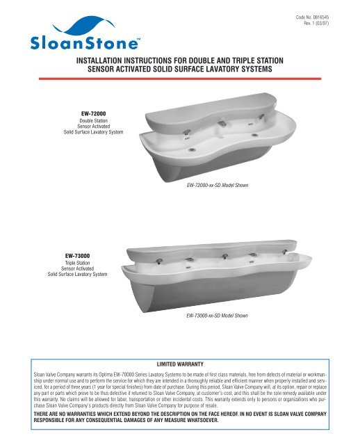
INSTALLATION INSTRUCTIONS FOR DOUBLE AND TRIPLE STATION<br />
SENSOR ACTIVATED SOLID SURFACE LAVATORY SYSTEMS<br />
<strong>EW</strong>-<strong>72000</strong><br />
Double Station<br />
Sensor Activated<br />
Solid Surface Lavatory System<br />
<strong>EW</strong>-<strong>72000</strong>-xx-SD Model Shown<br />
<strong>EW</strong>-<strong>73000</strong><br />
Triple Station<br />
Sensor Activated<br />
Solid Surface Lavatory System<br />
<strong>EW</strong>-<strong>73000</strong>-xx-SD Model Shown<br />
LIMITED WARRANTY<br />
<strong>Sloan</strong> <strong>Valve</strong> Company warrants its Optima <strong>EW</strong>-70000 Series Lavatory Systems to be made of first class materials, free from defects of material or workmanship<br />
under normal use and to perform the service for which they are intended in a thoroughly reliable and efficient manner when properly installed and serviced,<br />
for a period of three years (1 year for special finishes) from date of purchase. During this period, <strong>Sloan</strong> <strong>Valve</strong> Company will, at its option, repair or replace<br />
any part or parts which prove to be thus defective if returned to <strong>Sloan</strong> <strong>Valve</strong> Company, at customer’s cost, and this shall be the sole remedy available under<br />
this warranty. No claims will be allowed for labor, transportation or other incidental costs. This warranty extends only to persons or organizations who purchase<br />
<strong>Sloan</strong> <strong>Valve</strong> Company’s products directly from <strong>Sloan</strong> <strong>Valve</strong> Company for purpose of resale.<br />
THERE ARE NO WARRANTIES WHICH EXTEND BEYOND THE DESCRIPTION ON THE FACE HEREOF. IN NO EVENT IS SLOAN VALVE COMPANY<br />
RESPONSIBLE FOR ANY CONSEQUENTIAL DAMAGES OF ANY MEASURE WHATSOEVER.
LAVATORY SYSTEM ROUGH-IN<br />
MODEL <strong>EW</strong>-<strong>72000</strong><br />
Double Station Lavatory System<br />
Flow Rate: 0.5 gpm/1.9 Lpm Max. Spray<br />
Lavatory System Weight (Packaged):<br />
Approximately 145 Lbs/65 Kg<br />
MODEL <strong>EW</strong>-<strong>73000</strong><br />
Triple Station Lavatory System<br />
Flow Rate: 0.5 gpm/1.9 Lpm Max. Spray<br />
Lavatory System Weight (Packaged):<br />
Approximately 170 Lbs/80 Kg<br />
VARIABLE MOUNTING HEIGHT CHART<br />
DIMENSION T.A.S. † T.A.S. † A.D.A.<br />
DESCRIPTION AGES 4-10 AGES 11-15 STANDARD<br />
A ROUGH-IN 20-1/2” (521 mm) 22-1/2” (572 mm) 24” (610 mm)<br />
B RECOMMENDED RIM HEIGHT 29-7/8” (759 mm) 31-7/8” (810 mm) 33 (838 mm)<br />
C FLOOR CLEARANCE 10-7/8” (276 mm) 12-7/8” (327 mm) 14” (356 mm)<br />
D NOMINAL FRAME HEIGHT ‡ 25-1/8” (638 mm) 27-1/8 (689 mm) 28-1/4” (718 mm)<br />
† When no mirror is required above the basin.<br />
For T.A.S. compliant installations requiring a mirror above the basin, use ELS-<strong>72000</strong><br />
products.<br />
‡ Refer to Step 3.<br />
2
PRIOR TO INSTALLATION<br />
Prior to installing the <strong>Sloan</strong> Optima <strong>EW</strong>-70000 Series Lavatory System,<br />
install the items listed below. Also, refer to the appropriate rough-in<br />
diagram on Page 2.<br />
• Install electrical receptacle(s) for plug-in transformer(s) — 120 VAC,<br />
2 amp service for each ETF-233 (24 VAC, 35 VA) plug-in transformer<br />
used.<br />
• Hot and cold water supply lines or tempered water supply line (If there<br />
is no tempered water supply, install thermostatic mixing valve<br />
between hot and cold water supply)<br />
• Drain lines<br />
Important:<br />
• ADEQUATE STRUCTURAL SUPPORT IN OR BEHIND THE WALL IS<br />
REQUIRED. REFER TO THE APPROPRIATE ROUGH-IN DIAGRAM ON<br />
PAGE 2 FOR DRY WEIGHT OF SINK. STRUCTURAL SUPPORT<br />
MUST HAVE A MINIMUM PULLOUT RATING OF 1000 POUNDS<br />
(450 Kg) FOR EACH FASTENER.<br />
• ALL ELECTRICAL WIRING SHOULD BE INSTALLED IN ACCORDANCE<br />
WITH NATIONAL/LOCAL CODES AND REGULATIONS.<br />
• ALL PLUMBING SHOULD BE INSTALLED IN ACCORDANCE WITH<br />
APPLICABLE CODES AND REGULATIONS.<br />
• A 24 VAC STEP-DOWN TRANSFORMER MUST BE USED FOR<br />
HARDWIRE APPLICATIONS.<br />
• USE APPROPRIATE PRECAUTIONS WHILE CONNECTING<br />
TRANSFORMER TO 120 VAC POWER SOURCE.<br />
• DO NOT PLUG TRANSFORMER INTO POWER SOURCE (RECEPTACLE)<br />
UNTIL ALL WIRING IS COMPLETED. PERMANENT DAMAGE TO THE<br />
TRANSFORMER AND CIRCUIT CONTROL MODULE WILL RESULT IF<br />
24 VAC WIRES TOUCH EACH OTHER OR SHORT WHEN POWER<br />
SUPPLY IS ACTIVE.<br />
• BEFORE CONNECTING FLEX HOSES TO SUPPLY STOPS, FLUSH ALL<br />
WATER LINES UNTIL WATER IS CLEAR.<br />
TOOLS REQUIRED FOR INSTALLATION<br />
• Electric drill for drilling anchor holes.<br />
• Standard sockets and open end wrench set for installing anchoring<br />
fasteners and connecting water lines.<br />
• Pipe wrench for installing drain lines.<br />
• Phillips and straight blade screwdrivers.<br />
SINK LOCATION<br />
Determine the appropriate wall location for the Lavatory System.<br />
Consider that hot and cold water supply lines, drain lines, and an<br />
electrical source (receptacle or wiring depending on type of transformer<br />
used) will be required. Compare the physical dimensions of the Lavatory<br />
System to the space available for the installation. If wall is not load<br />
bearing, a carrier may be required behind the wall. Refer to the<br />
appropriate Rough-in diagram on Page 2 for Lavatory System<br />
dimensions.<br />
Prior to Lavatory System installation, electric wiring, water supply and<br />
drain must be installed.<br />
1<br />
Install<br />
Thermostatic Mixing <strong>Valve</strong><br />
2<br />
Remove<br />
End Caps from Frame<br />
A<br />
If there is no tempered water supply, install Thermostatic Mixing<br />
<strong>Valve</strong> between hot and cold water supply.<br />
A<br />
Loosen (do not remove) screws on inside of frame.<br />
B<br />
Remove both End<br />
Caps by removing<br />
the two outer screws<br />
on each Cap. Slide<br />
Cap forward in slot<br />
and pull it out<br />
through enlarged<br />
hole in Frame.<br />
Bottom Backside of Frame<br />
Enlarged Hole and<br />
Slot in Frame<br />
Front of Frame<br />
End Cap (2)<br />
C<br />
For triple station sinks,<br />
remove the Front Panel<br />
Support.<br />
3<br />
Front Panel Support
3<br />
Mount<br />
A<br />
If desired, apply adhesive to back<br />
surfaces of Frame.<br />
B<br />
Mount Frame to wall using 3/8" fasteners with 1000 lb min<br />
pull out strength in the following locations:<br />
1. Each hole in the extreme outer corners of top support<br />
2. One of either of the two holes in the top position of each upright<br />
3. The lower hole location in each upright<br />
Fasteners may be optionally applied to any of the remaining mounting hole locations.<br />
Level Frame in both directions before tightening fasteners securely.<br />
Frame to Wall<br />
4<br />
Double Station<br />
Triple Station<br />
D<br />
(See VARIABLE<br />
MOUNTING<br />
HEIGHT CHART<br />
On Page 2)<br />
FINISHED FLOOR<br />
C<br />
For triple station sinks, reinstall the Front Panel<br />
Support.<br />
Front Panel Support<br />
4<br />
Mount<br />
Basin to Frame<br />
Note: If desired, Grid Strainers may be installed prior to mounting<br />
Basin to the Frame. Refer to Step 5.<br />
1/4”-20 x 1/2” Pan Head Screw (SEMS)<br />
(Actual Size)<br />
A Mount Basin to Frame using 1/4”-20 x 1/2” SEMS fasteners. B If desired, apply caulk between Basin and wall.<br />
Double Station<br />
Triple Station
5<br />
Install<br />
Grid Strainers and Connect<br />
Drain Line<br />
6<br />
Remove<br />
Cover from Head<br />
A<br />
Install Grid Strainers.<br />
Grid Strainer<br />
A<br />
Insert T-Handled Wrench into access holes on left and right<br />
sides of the Head. Turn top of wrench toward front of Head<br />
rotating until it stops to fully open the latch. Remove the Cover.<br />
T-Handle<br />
Wrench<br />
B<br />
Plumb drain outlets to wall.<br />
Drain Line<br />
T-Handle<br />
Wrench<br />
7<br />
Mount<br />
Head to Basin<br />
1/4”-20 x 1-1/2” Truss Head Screw<br />
(Actual Size)<br />
A<br />
If desired, apply caulk between Basin and Head.<br />
B<br />
Mount Head to Basin using 1/4”-20 x 1-1/2” Truss Head<br />
Screws.<br />
Double Station<br />
Triple Station<br />
Fastener (4)<br />
Fastener (6)<br />
Bead of<br />
Caulk<br />
Bead of<br />
Caulk<br />
5
8<br />
Connect<br />
Supply Line to Shut Off<br />
<strong>Valve</strong> in Head<br />
9<br />
Connect<br />
Supply Line to<br />
Thermostatic Mixing <strong>Valve</strong><br />
A<br />
Drop Power Cord through service access hole.<br />
A<br />
Install water line.<br />
B<br />
Drop Braided Hose Supply Line through service access hole.<br />
C<br />
Connect Braided Hose Supply Line to right side of Shut Off<br />
<strong>Valve</strong> in Head.<br />
Note: To ease Supply Line installation, remove the two screws<br />
holding the Shut Off <strong>Valve</strong> Bracket. After connecting Supply Line,<br />
reinstall the Shut Off <strong>Valve</strong> Bracket.<br />
SHUT OFF VALVE<br />
BRACKET<br />
SHUT OFF<br />
VALVE<br />
BRAIDED HOSE<br />
SUPPLY LINE<br />
SERVICE ACCESS<br />
HOLE<br />
10<br />
Connect Power Cable to<br />
Transformer and Plug Transformer<br />
into Receptacle<br />
11<br />
Open Shut Off <strong>Valve</strong>, Turn on Water<br />
Supply, Check for Water Leaks and<br />
Install End Caps<br />
A<br />
Connect Spade Terminals<br />
on Power Cord to the<br />
Transformer.<br />
A<br />
B<br />
Open Shut Off <strong>Valve</strong> and turn on water supply.<br />
Check all plumbing for water leaks.<br />
Double Station Sink Shown<br />
Shut Off<br />
<strong>Valve</strong><br />
END CAP<br />
B<br />
Plug Transformer into<br />
outlet.<br />
6<br />
C<br />
Replace End Caps. Insert the screw located on the inside of the<br />
Cap into the enlarged hole of the Frame. Then slide the Cap into<br />
place. Loosely install the two front screws. Slide End Cap UP to<br />
eliminate any gap between the End Cap and Basin. Tighten the<br />
inside screw securely. Lastly, tighten the two front screws<br />
securely. Follow the same procedure for the second End Cap.
12<br />
Install Cover and Front Panel(s)<br />
A<br />
Replace Cover and latch firmly in place with T-Handled Wrench<br />
(Rotate top of handle toward wall until latch snaps into<br />
position).<br />
B<br />
Replace Front Panel(s) by hanging top lip of Panel into track of<br />
Trim Rail under Basin. Swing panel into position and affix with 2<br />
Fasteners. Triple Station Models — repeat this procedure for<br />
second panel.<br />
Double Station<br />
T-Handle<br />
Wrench<br />
Triple Station<br />
T-Handle<br />
Wrench<br />
Cover<br />
Cover<br />
T-Handle<br />
Wrench<br />
T-Handle<br />
Wrench<br />
Front Panel<br />
Fastener (2)<br />
Front Panel (2)<br />
Fastener (4)<br />
Solenoid Screen Filter Cleaning<br />
Troubleshooting Guide<br />
A<br />
B<br />
D<br />
E<br />
F<br />
G<br />
H<br />
Before cleaning the Screen Filter, turn off the water supply at<br />
supply stop(s).<br />
Activate the Spray Head to relieve any pressure in the system.<br />
C Remove Cover as instructed in Step 6.<br />
Unscrew the Filter Cap and remove it from the Solenoid <strong>Valve</strong><br />
Housing.<br />
Carefully remove the Screen Filter from the Solenoid <strong>Valve</strong><br />
Housing.<br />
Clean the Screen Filter using fresh tap water only. If necessary,<br />
use a small brush to clean. Use caution while cleaning to<br />
prevent damage to Screen Filter.<br />
Examine the Copper Washer for wear or damage; replace if<br />
necessary. Carefully replace the Screen Filter into the Filter Cap.<br />
Screw the Filter Cap with Copper Washer into the Solenoid<br />
<strong>Valve</strong> Housing and tighten securely to prevent leaks.<br />
Turn on the water supply at the supply stop(s). Activate the<br />
Spray Head to purge any air from the system lines. Check for<br />
leaks and repair as necessary.<br />
I Install Cover as instructed in Step 12.<br />
1. No water flows when sensor is activated<br />
Ensure that main power supply is turned “ON.” Check receptacle,<br />
transformer, solenoid, leads and connections.<br />
If Sensor LED does not blink:<br />
A. Control module circuit board is faulty; replace.<br />
B. Sensor is faulty; replace sensor module.<br />
If Sensor LED blinks when user is sensed:<br />
A. Supply Stop(s) may be closed; open Supply Stop(s).<br />
B. Debris may be in Solenoid filter; remove, clean and reinstall.<br />
2. Very low flow or slow dribble<br />
A. Supply Stop(s) may be closed; open Supply Stop(s).<br />
B. Debris is in solenoid, won’t close properly; remove operator<br />
and clean. Reassemble in the same manner.<br />
C. Debris is in Solenoid filter; remove, clean and reinstall.<br />
D. Debris is in spray head; remove, clean and reinstall.<br />
3. Continues to run (even after power to faucet has been<br />
disconnected)<br />
A. Solenoid valve is installed backwards; install correctly.<br />
B. Debris is in solenoid, won’t close properly; remove operator<br />
and clean. Reassemble in the same manner.<br />
7
Parts List<br />
25 28<br />
29<br />
<strong>EW</strong>-<strong>72000</strong> Double Station Head Assembly<br />
30<br />
7<br />
22 31<br />
26<br />
27<br />
3<br />
2<br />
20<br />
16<br />
1<br />
5<br />
24<br />
21<br />
4<br />
12<br />
13<br />
23 17 19 10 18 15<br />
14<br />
9<br />
8<br />
11<br />
6<br />
Item Part Description<br />
No. No.<br />
1 <strong>EW</strong>-46 Electronics Enclosure 2 Station Machined<br />
2 <strong>EW</strong>-41 Large Latch (2)<br />
3 <strong>EW</strong>-27 Screw, Flat Head #10-24 x 1/2” Long (4)<br />
4 <strong>EW</strong>-75-A Sensor Plate Assembly (2)<br />
5 <strong>EW</strong>-8 Spacer, #8 x 1” Long (4)<br />
6 <strong>EW</strong>-13 Mounting Clamp for ETF-370-A Solenoid (4)<br />
7 <strong>EW</strong>-9 Screw, Truss Head #8-32 x 1-1/2” Long (4)<br />
8 ETF-61 Male Connector (4)<br />
9 ETF-370-A Solenoid <strong>Valve</strong> Assembly (2)<br />
10 <strong>EW</strong>-19 Compression Tee Fitting 3/8" Tube<br />
11 <strong>EW</strong>-89-00362 Tube, 3/8" x 3-5/8” Long (2)<br />
12 <strong>EW</strong>-89-00188 Tube, 3/8" x 1-7/8” Long (2)<br />
13 <strong>EW</strong>-18 Compression Elbow Fitting, 3/8" Tube<br />
14 <strong>EW</strong>-5 Mounting Bracket for Shut-off <strong>Valve</strong><br />
15 <strong>EW</strong>-74 Panel Mount Ball <strong>Valve</strong> - 3/8" Compression<br />
Fitting<br />
16 <strong>EW</strong>-36 Screw, Pan Head #8-32 x 7/16” Long (SEMS)(2)<br />
17 <strong>EW</strong>-89-02525 Tube, 3/8" x 25-1/4” Long<br />
18 <strong>EW</strong>-89-00388 Tube, 3/8" x 3-7/8” Long<br />
19 ETF-450-A Splash Proof Junction Box Assembly (2)<br />
20 <strong>EW</strong>-28 Screw, Round Head #8-32 x 1/2” Long (4)<br />
21 † ESD-255-A Manual Soap Pump Assembly<br />
8<br />
Item Part<br />
Description<br />
No. No.<br />
22 † ESD-245-A Manual Soap Reservoir Assembly<br />
23 <strong>EW</strong>-37 Screw, Truss Head 1/4-20 x 1-1/2” (4)<br />
— <strong>EW</strong>-26 Tube Support 3/8" (5) (Not Shown)<br />
— MIX-135-A Thermostatic Mixing <strong>Valve</strong> (Below Deck)<br />
(Not shown)<br />
— <strong>EW</strong>-87 Flexible Supply Hose, 2 Station (Not Shown)<br />
— <strong>EW</strong>-82-A Wiring Harness, 2 Station (Not Shown)<br />
— ETF-233 Transformer (Not shown)<br />
— ETF-731 Vandal Proof Key, Standard and Junior<br />
(Not shown)<br />
24 <strong>EW</strong>-96 T-Handle Hex Wrench, 7/32"<br />
25 <strong>EW</strong>-48-X Cover, Electronics Enclosure, 2 Station Machined<br />
26 <strong>EW</strong>-42 Large Encased Receiver (2)<br />
27 <strong>EW</strong>-27 Screw, Flat Head #10-24 x 1/2” Long (4)<br />
28 ‡ ESD-242 Sleeve for Fill Cap<br />
29 ‡ ESD-241 Fill Cap for Soap Reservoir<br />
30 ‡ <strong>EW</strong>-11 Gasket - Fill Cap Sleeve (Manual Soap Reservoir)<br />
31 ‡ ESD-243 Jam Nut for Fill Cap Sleeve<br />
— ‡ ESD-249 Fill Cap Spanner (Not Shown)<br />
† Included on models with Soap Dispenser.<br />
‡ Included on models with Fill Cap.
Parts List<br />
<strong>EW</strong>-<strong>72000</strong> Double Station Cabinet and Basin Assemblies<br />
8<br />
5<br />
9<br />
11<br />
10<br />
4<br />
2<br />
7<br />
6<br />
3<br />
1<br />
Item Part Description<br />
No. No.<br />
1 <strong>EW</strong>-20-A Cabinet Weldment, 2 Station<br />
2 <strong>EW</strong>-99 U-Type Nut Standard 1/4-20 Thread (6)<br />
3 <strong>EW</strong>-60 End Cap Right - Machined<br />
4 <strong>EW</strong>-52 End Cap Left - Machined<br />
5 <strong>EW</strong>-15 Screw, Pan Head 1/4-20 x 1/2” Long (SEMS) (4)<br />
6 <strong>EW</strong>-16 Screw, Pan Head 1/4-20 x 1” Long (SEMS) (4)<br />
7 <strong>EW</strong>-25 Front Panel, 2 Station<br />
Item Part Description<br />
No. No.<br />
8 <strong>EW</strong>-44 Basin 2-Station Machined<br />
9 ETF-725-A Grid Strainer Assembly (2)<br />
10 <strong>EW</strong>-15 Screw, Pan Head 1/4-20 x 1/2” Long (SEMS) (6)<br />
11 <strong>EW</strong>-61 Overflow Cover Plate (2)<br />
— <strong>EW</strong>-98 Light Duty Buffing Pad (Not Shown)<br />
9
Parts List<br />
24<br />
28<br />
27<br />
<strong>EW</strong>-<strong>73000</strong> Triple Station Head Assembly<br />
7<br />
22<br />
29<br />
30<br />
25<br />
26<br />
2<br />
17<br />
1<br />
3<br />
21<br />
20<br />
5<br />
4<br />
13<br />
23<br />
19<br />
14<br />
12<br />
15 18<br />
16<br />
9<br />
8<br />
11<br />
6 10<br />
Item Part Description<br />
No. No.<br />
1 <strong>EW</strong>-56 Electronics Enclosure, 3 Station Machined<br />
2 <strong>EW</strong>-41 Large Latch (2)<br />
3 <strong>EW</strong>-27 Screw, Flat Head #10-24 x 1/2” Long (4)<br />
4 <strong>EW</strong>-75-A Sensor Plate Assembly (3)<br />
5 <strong>EW</strong>-8 Spacer #8 x 1” Long (6)<br />
6 <strong>EW</strong>-13 Mounting Clamp ETF-370-A Solenoid (6)<br />
7 <strong>EW</strong>-9 Screw, Truss Head #8-32 x 1-1/2” Long (6)<br />
8 ETF-61 Male Connector (6)<br />
9 ETF-370-A Solenoid <strong>Valve</strong> Assembly (3)<br />
10 <strong>EW</strong>-89-00362 Tube 3/8” x 3-5/8” Long (3)<br />
11 <strong>EW</strong>-89-00188 Tube 3/8” x 1-7/8” Long (3)<br />
12 <strong>EW</strong>-19 Compression Tee Fitting 3/8” Tube (2)<br />
13 <strong>EW</strong>-18 Compression Elbow Fitting 3/8” Tube<br />
14 <strong>EW</strong>-89-02525 Tube 3/8” x 25-1/4” Long (2)<br />
15 <strong>EW</strong>-89-00388 Tube 3/8” x 3-7/8” Long (1)<br />
16 <strong>EW</strong>-5 Mounting Bracket for Shut-off <strong>Valve</strong><br />
17 <strong>EW</strong>-36 Screw, Pan Hd #8-32 x 7/16” Long (SEMS) (2)<br />
18 <strong>EW</strong>-74 Panel Mount Ball <strong>Valve</strong> - 3/8” Compression<br />
Fitting<br />
19 ETF-450-A Splash Proof Junction Box Assembly (3)<br />
20 <strong>EW</strong>-28 Screw, Round Head #8-32 x 1/2” Long (6)<br />
21 † ESD-255-A Manual Soap Pump Assembly (2)<br />
10<br />
Item Part Description<br />
No. No.<br />
22 † ESD-245-A Soap Reservoir Assembly (2)<br />
23 <strong>EW</strong>-37 Screw, Truss Head 1/4-20 x 1-1/2” Long (6)<br />
(Not Shown)<br />
— <strong>EW</strong>-26 Tube Support 3/8” (7) (Not Shown)<br />
— MIX-135-A Thermostatic Mixing <strong>Valve</strong> (Below Deck)<br />
(Not Shown)<br />
— <strong>EW</strong>-92-A Wiring Harness 3 Station (Not Shown)<br />
— ETF-233 Transformer (Not Shown)<br />
— ETF-731 Vandal Proof Key, Standard and Junior (Not<br />
Shown)<br />
— <strong>EW</strong>-97 Flexible Supply Hose, 3 Station (Not Shown)<br />
— <strong>EW</strong>-96 T-Handle Hex Wrench 7/32” (Not Shown)<br />
24 <strong>EW</strong>-58-X Cover, Electronics Enclosure, 3 Station Machined<br />
25 <strong>EW</strong>-42 Large Encased Receiver (2)<br />
26 <strong>EW</strong>-27 Screw, Flat Head #10-24 x 1/2” Long (4)<br />
27 ‡ ESD-242 Sleeve for Fill Cap (2)<br />
28 ‡ ESD-241 Fill Cap for Soap Reservoir (2)<br />
29 ‡ <strong>EW</strong>-11 Gasket for Fill Cap Sleeve (2)<br />
30 ‡ ESD-243 Jam Nut for Fill Cap Sleeve (2)<br />
— ‡ ESD-249 Fill Cap Spanner (Not Shown)<br />
† Included on models with Soap Dispenser.<br />
‡ Included on models with Fill Cap.
Parts List<br />
<strong>EW</strong>-<strong>73000</strong> Triple Station Cabinet and Basin Assemblies<br />
10<br />
6<br />
13<br />
11<br />
4<br />
8<br />
12<br />
9<br />
2<br />
5<br />
3 1 7<br />
Item Part Description<br />
No. No.<br />
1 <strong>EW</strong>-30-A Cabinet Weldment, 3 Station<br />
2 <strong>EW</strong>-50 Front Panel Support - Machined<br />
3 <strong>EW</strong>-36 Screw, Pan Head #8-32 x 7/16” Long (SEMS) (2)<br />
4 <strong>EW</strong>-99 U-type Nut, Standard 1/4-20 Thread (8)<br />
5 <strong>EW</strong>-60 End Cap Right - Machined<br />
6 <strong>EW</strong>-52 End Cap Left - Machined<br />
7 <strong>EW</strong>-16 Screw, Pan Head 1/4-20 x 1” Long (SEMS) (4)<br />
Item Part Description<br />
No. No.<br />
8 <strong>EW</strong>-15 Screw, Pan Head 1/4-20 x 1/2” Long (SEMS) (2)<br />
9 <strong>EW</strong>-35 Front Panel, 3 Station (2)<br />
10 <strong>EW</strong>-54 Triple Station Lavatory Basin Assembly<br />
11 ETF-725-A Grid Strainer Assembly (2)<br />
12 <strong>EW</strong>-15 Screw, Pan Head 1/4-20 x 1/2” Long (SEMS) (8)<br />
13 <strong>EW</strong>-61 Overflow Cover Plate (2)<br />
— <strong>EW</strong>-98 Light Duty Buffing Pad (Not Shown)<br />
Operation<br />
As the user’s hands pass under the spray head and enter the beam’s effective<br />
range, the beam is reflected back into the sensor receiver and activates the<br />
solenoid valve allowing water to flow from the Spray Head. Water will flow until<br />
the user’s hands are removed from under the Spray Head or until the automatic<br />
time out limit setting is reached.<br />
When assistance is required, please contact <strong>Sloan</strong> <strong>Valve</strong> Company <strong>Installation</strong> Engineering Department at:<br />
1-888-SLOAN-14 (1-888-756-2614)<br />
OR<br />
1-847-233-2016<br />
The information contained in this document is subject to change without notice.<br />
Copyright © 2007 SLOAN VALVE COMPANY<br />
SLOAN VALVE COMPANY • 10500 Seymour Avenue • Franklin Park, IL 60131<br />
Phone: 1-800-9-VALVE-9 or 1-847-671-4300 • Fax: 1-800-447-8329 or 1-847-671-4380<br />
www.sloanvalve.com<br />
Printed in the U.S.A. 03-07


