

ELC and ELB Lavatory Series Installation Instructions - Sloan Valve ...
ELC and ELB Lavatory Series Installation Instructions - Sloan Valve ...
ELC and ELB Lavatory Series Installation Instructions - Sloan Valve ...

Create successful ePaper yourself
Turn your PDF publications into a flip-book with our unique Google optimized e-Paper software.
Code No. 0816547<br />
Rev. 1 (12/10)<br />
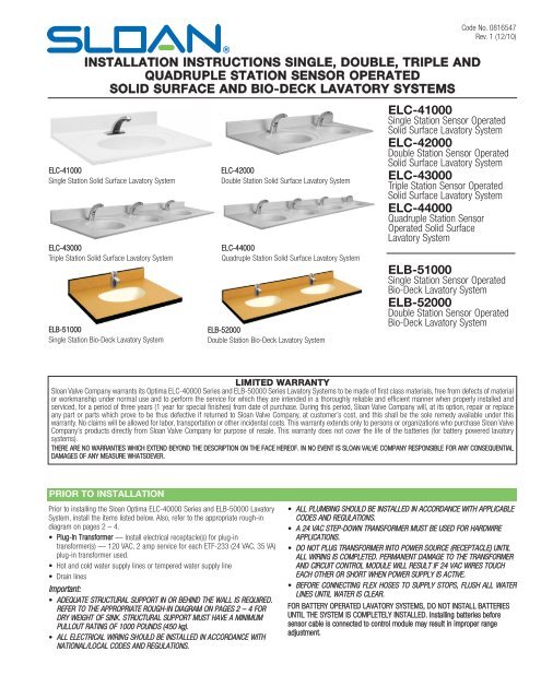
INSTALLATION INSTRUCTIONS SINGLE, DOUBLE, TRIPLE AND<br />
QUADRUPLE STATION SENSOR OPERATED<br />
SOLID SURFACE AND BIO-DECK LAVATORY SYSTEMS<br />
<strong>ELC</strong>-41000<br />
Single Station Solid Surface <strong>Lavatory</strong> System<br />
<strong>ELC</strong>-43000<br />
Triple Station Solid Surface <strong>Lavatory</strong> System<br />
<strong>ELB</strong>-51000<br />
Single Station Bio-Deck <strong>Lavatory</strong> System<br />
<strong>ELC</strong>-42000<br />
Double Station Solid Surface <strong>Lavatory</strong> System<br />
<strong>ELC</strong>-44000<br />
Quadruple Station Solid Surface <strong>Lavatory</strong> System<br />
<strong>ELB</strong>-52000<br />
Double Station Bio-Deck <strong>Lavatory</strong> System<br />
<strong>ELC</strong>-41000<br />
Single Station Sensor Operated<br />
Solid Surface <strong>Lavatory</strong> System<br />
<strong>ELC</strong>-42000<br />
Double Station Sensor Operated<br />
Solid Surface <strong>Lavatory</strong> System<br />
<strong>ELC</strong>-43000<br />
Triple Station Sensor Operated<br />
Solid Surface <strong>Lavatory</strong> System<br />
<strong>ELC</strong>-44000<br />
Quadruple Station Sensor<br />
Operated Solid Surface<br />
<strong>Lavatory</strong> System<br />
<strong>ELB</strong>-51000<br />
Single Station Sensor Operated<br />
Bio-Deck <strong>Lavatory</strong> System<br />
<strong>ELB</strong>-52000<br />
Double Station Sensor Operated<br />
Bio-Deck <strong>Lavatory</strong> System<br />
LIMITED WARRANTY<br />
<strong>Sloan</strong> <strong>Valve</strong> Company warrants its Optima <strong>ELC</strong>-40000 <strong>Series</strong> <strong>and</strong> <strong>ELB</strong>-50000 <strong>Series</strong> <strong>Lavatory</strong> Systems to be made of first class materials, free from defects of material<br />
or workmanship under normal use <strong>and</strong> to perform the service for which they are intended in a thoroughly reliable <strong>and</strong> efficient manner when properly installed <strong>and</strong><br />
serviced, for a period of three years (1 year for special finishes) from date of purchase. During this period, <strong>Sloan</strong> <strong>Valve</strong> Company will, at its option, repair or replace<br />
any part or parts which prove to be thus defective if returned to <strong>Sloan</strong> <strong>Valve</strong> Company, at customer’s cost, <strong>and</strong> this shall be the sole remedy available under this<br />
warranty. No claims will be allowed for labor, transportation or other incidental costs. This warranty extends only to persons or organizations who purchase <strong>Sloan</strong> <strong>Valve</strong><br />
Company’s products directly from <strong>Sloan</strong> <strong>Valve</strong> Company for purpose of resale. This warranty does not cover the life of the batteries (for battery powered lavatory<br />
systems).<br />
THERE ARE NO WARRANTIES WHICH EXTEND BEYOND THE DESCRIPTION ON THE FACE HEREOF. IN NO EVENT IS SLOAN VALVE COMPANY RESPONSIBLE FOR ANY CONSEQUENTIAL<br />
DAMAGES OF ANY MEASURE WHATSOEVER.<br />
PRIOR TO INSTALLATION<br />
Prior to installing the <strong>Sloan</strong> Optima <strong>ELC</strong>-40000 <strong>Series</strong> <strong>and</strong> <strong>ELB</strong>-50000 <strong>Lavatory</strong><br />
System, install the items listed below. Also, refer to the appropriate rough-in<br />
diagram on pages 2 – 4.<br />
• Plug-In Transformer — Install electrical receptacle(s) for plug-in<br />
transformer(s) — 120 VAC, 2 amp service for each ETF-233 (24 VAC, 35 VA)<br />
plug-in transformer used.<br />
• Hot <strong>and</strong> cold water supply lines or tempered water supply line<br />
• Drain lines<br />
Important:<br />
• ADEQUATE STRUCTURAL SUPPORT IN OR BEHIND THE WALL IS REQUIRED.<br />
REFER TO THE APPROPRIATE ROUGH-IN DIAGRAM ON PAGES 2 – 4 FOR<br />
DRY WEIGHT OF SINK. STRUCTURAL SUPPORT MUST HAVE A MINIMUM<br />
PULLOUT RATING OF 1000 POUNDS (450 kg).<br />
• ALL ELECTRICAL WIRING SHOULD BE INSTALLED IN ACCORDANCE WITH<br />
NATIONAL/LOCAL CODES AND REGULATIONS.<br />
• ALL PLUMBING SHOULD BE INSTALLED IN ACCORDANCE WITH APPLICABLE<br />
CODES AND REGULATIONS.<br />
• A 24 VAC STEP-DOWN TRANSFORMER MUST BE USED FOR HARDWIRE<br />
APPLICATIONS.<br />
• DO NOT PLUG TRANSFORMER INTO POWER SOURCE (RECEPTACLE) UNTIL<br />
ALL WIRING IS COMPLETED. PERMANENT DAMAGE TO THE TRANSFORMER<br />
AND CIRCUIT CONTROL MODULE WILL RESULT IF 24 VAC WIRES TOUCH<br />
EACH OTHER OR SHORT WHEN POWER SUPPLY IS ACTIVE.<br />
• BEFORE CONNECTING FLEX HOSES TO SUPPLY STOPS, FLUSH ALL WATER<br />
LINES UNTIL WATER IS CLEAR.<br />
FOR BATTERY OPERATED LAVATORY SYSTEMS, DO NOT INSTALL BATTERIES<br />
UNTIL THE SYSTEM IS COMPLETELY INSTALLED. Installing batteries before<br />
sensor cable is connected to control module may result in improper range<br />
adjustment.
LAVATORY SYSTEM ROUGH-IN<br />
Single Station <strong>Lavatory</strong> System<br />
MODEL <strong>ELC</strong>-41000 SERIES — 0.5 gpm (1.9 Lpm) Max. — Aerator<br />
LAVATORY SYSTEM WEIGHT (Empty) — 60 Lbs. (27 kg)<br />
Single Station<br />
15½”<br />
<strong>Lavatory</strong> System<br />
15½”<br />
(394 mm)<br />
(394 mm)<br />
MODEL <strong>ELB</strong>-51000 SERIES<br />
31”<br />
LAVATORY SYSTEM WEIGHT (762(Less mm) Faucet <strong>and</strong> Empty) — 68 Lbs. (31 kg)<br />
15½”<br />
(394 mm)<br />
31”<br />
(762 mm)<br />
15½”<br />
(394 mm)<br />
2
LAVATORY SYSTEM ROUGH-IN<br />
Double Station <strong>Lavatory</strong> System<br />
MODEL <strong>ELC</strong>-42000 SERIES — 0.5 gpm (1.9 Lpm) Max. — Aerator<br />
LAVATORY SYSTEM WEIGHT (Empty) — 120 Lbs. (54 kg)<br />
Double Station <strong>Lavatory</strong> System<br />
MODEL <strong>ELB</strong>-52000 SERIES<br />
LAVATORY SYSTEM WEIGHT (Less Faucet <strong>and</strong> Empty) — 131 Lbs. (59 kg)<br />
15”<br />
(381 mm)<br />
15½”<br />
(394 mm)<br />
15½”<br />
(394 mm)<br />
31”<br />
(762 mm)<br />
30”<br />
(762 mm)<br />
60”<br />
(1524 mm)<br />
15”<br />
(381 mm)<br />
3
LAVATORY SYSTEM ROUGH-IN<br />
Triple Station <strong>Lavatory</strong> System<br />
MODEL <strong>ELC</strong>-43000 SERIES — 0.5 gpm (1.9 Lpm) Max. — Aerator<br />
LAVATORY SYSTEM WEIGHT (Empty) — 180 Lbs. (81 kg)<br />
Quadruple Station <strong>Lavatory</strong> System<br />
MODEL <strong>ELC</strong>-44000 SERIES — 0.5 gpm (1.9 Lpm) Max. — Aerator<br />
LAVATORY SYSTEM WEIGHT (Empty) — 240 Lbs. (108 kg)<br />
TOOLS REQUIRED FOR INSTALLATION<br />
• Electric drill for drilling anchor holes.<br />
• Socket or open end wrench for installing anchoring fasteners.<br />
• Open end wrench for connecting water lines.<br />
• Pipe wrench for installing drain lines.<br />
SINK LOCATION<br />
Determine the appropriate wall location for the <strong>Lavatory</strong> System. Consider that hot <strong>and</strong> cold water supply lines, a drain line, <strong>and</strong> an electrical source (receptacle) will<br />
be required. Compare the physical dimensions of the <strong>Lavatory</strong> System to the space available for the installation. If wall is not load bearing, a carrier may be required<br />
behind the wall. Refer to the appropriate Rough-in diagram on pages 2 – 4 for <strong>Lavatory</strong> System dimensions.<br />
Prior to <strong>Lavatory</strong> System installation, electric wiring, water supply <strong>and</strong> drain must be installed.<br />
4
1– STRAINER INSTALLATION<br />
A<br />
Insert Strainer into Basin using plumbers putty (supplied by installer).<br />
STRAINER<br />
B<br />
From beneath Basin, install the Rubber Gasket, Cardboard Seat <strong>and</strong><br />
Drain Nut onto Strainer. Secure Drain Nut against Basin.<br />
RUBBER GASKET<br />
CARDBOARD SEAT<br />
DRAIN NUT<br />
2A – VANITY MOUNTING<br />
A<br />
B<br />
Apply adhesive caulk to perimeter of vanity casework <strong>and</strong> corners of<br />
deck.<br />
With the help of another person, place the lavatory deck on vanity.<br />
2B – WALL MOUNTING (OPTIONAL)<br />
A<br />
B<br />
C<br />
D<br />
E<br />
F<br />
Note: Wall mounting fasteners supplied by others.<br />
Measure <strong>and</strong> mark a level line on the wall at 5/8” below the desired<br />
Basin height (this line is a guide for the top of all the brackets).<br />
Measure <strong>and</strong> mark the Bracket locations as shown. Drill holes in the<br />
wall using the Mounting Bracket as a template.<br />
Install wall anchors that are specific for that type of wall: drywall,<br />
concrete, metal studs, wood studs, etc. (supplied by installer). Some<br />
wall materials will require additional reinforcement.<br />
Secure Mounting Brackets to the wall. Use left <strong>and</strong> right Brackets as<br />
required.<br />
Note: Be sure Mounting Bracket is level <strong>and</strong> plumb against wall so<br />
that <strong>Lavatory</strong> will drain correctly once assembly is completed.<br />
FOR <strong>ELC</strong> SERIES – Apply adhesive to brackets <strong>and</strong> corners of lavatory<br />
deck. With the help of another person, place the <strong>Lavatory</strong> on the<br />
Mounting Brackets. Optional Step for <strong>ELB</strong> <strong>Series</strong>.<br />
Caution: Do not leave lavatory on mounting brackets unsupported.<br />
It may fall <strong>and</strong> cause damage or personal injury.<br />
FOR <strong>ELB</strong> SERIES – secure <strong>Lavatory</strong> with the hardware provided through<br />
the holes provided in the brackets.<br />
3 - INSTALL FAUCET, SENSOR, AND WATER LINE CONNECTIONS<br />
MOUNTING BRACKETS<br />
A<br />
Install faucet, sensor, <strong>and</strong> water line connections as instructed in the<br />
installation instructions furnished with the Faucet.<br />
C<br />
Flush supply line(s) of any debris. Install Flex Hose(s) to water supply<br />
line(s). Tighten fitting(s) securely.<br />
WALL<br />
STRAINER<br />
WATER<br />
SUPPLY<br />
LINE<br />
B<br />
Install P-trap <strong>and</strong> drain lines making sure that all connections are<br />
secure.<br />
Note: P-trap <strong>and</strong> drain lines furnished by others.<br />
DRAIN<br />
LINE<br />
FLEX HOSE<br />
P-TRAP<br />
5
4 – SUPPLY POWER TO LAVATORY SYSTEM<br />
A<br />
For Plug-in Transformer <strong>and</strong> Adapter installations, make sure that power<br />
is supplied to the receptacle. Once all wiring within the system is<br />
connected, plug the Transformer or Adapter into the receptacle.<br />
Important: Plug-in Transformer MUST be used with a Ground Fault Interrupt (GFCI)<br />
Receptacle to help prevent possible electrical shock.<br />
B<br />
For battery powered installations, once all wiring within the system is<br />
connected, install batteries into the control module as indicated by the<br />
"+" <strong>and</strong> "-" marks. Refer to the faucet installation instructions furnished<br />
with the Faucet.<br />
ETF-233<br />
PLUG-IN<br />
TRANSFORMER<br />
5 – START-UP<br />
A<br />
Turn on water supply to lavatory system. Check for leaks at water<br />
supply <strong>and</strong> drain lines. Repair any leaks.<br />
C<br />
Close Supply Stops <strong>and</strong> reinstall Aerator (using the Key provided).<br />
Reopen Supply Stops, activate Faucet <strong>and</strong> check for leaks.<br />
B With Aerator removed, activate Faucet for 30 seconds by st<strong>and</strong>ing in<br />
front of the Faucet. The Solenoid <strong>Valve</strong> should "click," Sensor LED<br />
indicator should blink <strong>and</strong> water should flow from the Faucet. If this<br />
does not occur, refer to the Troubleshooting section of this instruction<br />
manual.<br />
OPERATION<br />
As the users h<strong>and</strong>s enter the beam’s effective range, the beam is<br />
reflected back into the sensor receiver <strong>and</strong> activates the solenoid valve<br />
allowing water to flow from the Faucet. Water will flow until the user<br />
removes h<strong>and</strong>s from the Faucet or until the automatic time out limit<br />
setting is reached.<br />
SOLENOID SCREEN FILTER CLEANING<br />
A<br />
B<br />
Before cleaning the Screen Filter, turn off the water supply at supply<br />
stop(s).<br />
Activate the Faucet to relieve any pressure in the system.<br />
For Example:<br />
For Transformer Models*<br />
C<br />
D<br />
Unscrew the Filter Cap <strong>and</strong> remove it from the Solenoid <strong>Valve</strong> Housing.<br />
Carefully remove the Screen Filter from the Solenoid <strong>Valve</strong> Housing.<br />
SOLENOID<br />
VALVE<br />
E<br />
F<br />
G<br />
Clean the Screen Filter using fresh tap water only. If necessary, use a<br />
small brush to clean. Use caution while cleaning to prevent damage to<br />
Screen Filter.<br />
Examine the Copper Washer or O-ring for wear or damage; replace if<br />
necessary. Carefully replace the Screen Filter into Filter Cap. Screw the<br />
Filter Cap with Copper Washer or O-ring into Solenoid <strong>Valve</strong> Housing<br />
<strong>and</strong> tighten securely to prevent leaks.<br />
Turn on the water supply at the supply stop(s). Activate the Faucet to<br />
purge any air from the system lines. Check for leaks <strong>and</strong> repair as<br />
necessary.<br />
SCREEN FILTER<br />
COPPER WASHER<br />
FILTER CAP<br />
* Please contact a <strong>Sloan</strong> Representative or <strong>Sloan</strong> <strong>Valve</strong> Company<br />
<strong>Installation</strong> Engineering Department for further information on the model<br />
installed with lavatory for screen filter cleaning at 1-888-SLOAN-14<br />
(1-888-756-2614).<br />
6
TROUBLESHOOTING GUIDE<br />
I. No water flows when sensor is activated<br />
Ensure that main power supply is turned “ON.” Check receptacle,<br />
transformer, batteries (battery powered models), solenoid, leads <strong>and</strong><br />
connections.<br />
If Sensor LED does not blink:<br />
A. Control module circuit board is faulty; replace.<br />
B. Sensor is faulty; replace sensor module.<br />
If Sensor LED blinks when user is sensed:<br />
A. Supply Stop(s) may be closed; open Supply Stop(s).<br />
B. Debris may be in Solenoid filter; remove, clean <strong>and</strong> reinstall.ß<br />
CARE AND CLEANING<br />
II. Very low flow or slow dribble<br />
A. Supply Stop(s) may be closed; open Supply Stop(s).<br />
B. Debris is in solenoid, won’t close properly; remove operator<br />
<strong>and</strong> clean. Reassemble in the same manner.<br />
C. Debris may be in Solenoid filter; remove, clean <strong>and</strong> reinstall.<br />
D. Debris is in aerator; remove, clean <strong>and</strong> reinstall.<br />
III. Continues to run (even after power to faucet has been disconnected)<br />
A. Solenoid valve is installed backwards; install correctly.<br />
B. Debris is in solenoid, won’t close properly; remove operator<br />
<strong>and</strong> clean. Reassemble in the same manner.<br />
If further assistance is required, please contact the <strong>Sloan</strong> <strong>Valve</strong> Company <strong>Installation</strong><br />
Engineering Department at 1-888-SLOAN-14 (1-888-756-2614).<br />
DO NOT USE abrasive or chemical cleaners (including chlorine bleach) to clean lavatory deck or faucets that may dull the luster <strong>and</strong> attack the finish.<br />
Use ONLY soap <strong>and</strong> water, then wipe dry with clean cloth or towel.<br />
While cleaning the sink area, protect the faucet from any splattering of cleaner. Acids <strong>and</strong> cleaning fluids will discolor or remove chrome plating.<br />
PARTS LIST<br />
<strong>ELB</strong> <strong>Series</strong><br />
6<br />
6<br />
5<br />
1<br />
4<br />
3<br />
2<br />
4<br />
5<br />
7<br />
4<br />
3<br />
Item Part Description<br />
No. No.<br />
1 <strong>ELB</strong>-51000 Bio-Deck Surface – Single Station<br />
2 <strong>ELB</strong>-52000 Bio-Deck Surface – Double Station<br />
3 <strong>ELB</strong>-3 Right Mounting Bracket (Optional)<br />
4 <strong>ELB</strong>-4 Left Mounting Bracket (Optional)<br />
7<br />
Item Part Description<br />
No. No.<br />
5 SS-7 Vitreous China Undermount Sink<br />
6 ETF-460-A Grid Strainer Assembly<br />
7 <strong>ELB</strong>-7-A Mounting Hardware includes ¼” Fender Washer<br />
<strong>and</strong> ¼” x 1” Sheet Metal Screw<br />
– –– <strong>Sloan</strong> Faucet (model varies)
PARTS LIST<br />
<strong>ELC</strong> <strong>Series</strong><br />
1<br />
3<br />
2<br />
4<br />
1<br />
3<br />
2<br />
5<br />
1<br />
3<br />
1<br />
3<br />
2<br />
2<br />
Item<br />
No.<br />
Description<br />
1 Solid Surface Basin (single)<br />
Solid Surface Basin (double)<br />
Solid Surface Basin (triple)<br />
Solid Surface Basin (quadruple)<br />
2 Faucet (Model Varies)<br />
3 Strainer Assembly<br />
4 Right Mounting Bracket (Optional)<br />
5 Left Mounting Bracket (Optional)<br />
NOTICE:<br />
The information contained in this document is subject to change without notice.<br />
SLOAN VALVE COMPANY • 10500 SEYMOUR AVENUE • FRANKLIN PARK, IL 60131<br />
Phone: 1-800-9-VALVE-9 or 1-847-671-4300 • Fax: 1-800-447-8329 or 1-847-671-4380 • www.sloanvalve.com<br />
COPYRIGHT © 2010 SLOAN VALVE COMPANY Code No. 0816547 – Rev. 1 (12/10)


