

900 Series Flushometers - Sloan Valve Company
900 Series Flushometers - Sloan Valve Company
900 Series Flushometers - Sloan Valve Company

You also want an ePaper? Increase the reach of your titles
YUMPU automatically turns print PDFs into web optimized ePapers that Google loves.
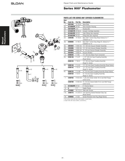
Repair Parts and Maintenance Guide<br />
<strong>Series</strong> <strong>900</strong> ® Flushometer<br />
PARTS LIST FOR SERIES <strong>900</strong> ® EXPOSED FLUSHOMETER<br />
Manual<br />
<strong>Flushometers</strong><br />
9<br />
10<br />
8<br />
4A<br />
6A<br />
2E<br />
2D<br />
2A<br />
4D<br />
5<br />
2C<br />
2B<br />
6A<br />
7<br />
1<br />
4C<br />
6C<br />
3A<br />
11A<br />
4B<br />
6B<br />
3B<br />
11B<br />
Item<br />
No. Code No. Part No. Description<br />
1. 0301048 A-143-A <strong>Valve</strong> Body<br />
2A. 0318065PK HY-65 <strong>Valve</strong> Actuator Housing<br />
2B. 0301082PK A-6 Housing Nut<br />
2C. 3318001PK HY-83-A Actuator Cartridge Assembly<br />
2D. 0318023PK HY-24 Tube Fittings (two required)<br />
2E. 0318033PK HY-35 Fitting Nuts (two required)<br />
3A. 3308386 H-700-A Bak-Chek ® Control Stop (Royal <strong>Valve</strong>s) for 1”<br />
3308384 for ¾”<br />
3B. 0388065 H-790-A Bak-Chek ® Control Stop (Regal XL <strong>Valve</strong>s) for 1”<br />
0388064 for ¾”<br />
4A. 3893004 V-600-AA 1½” (38 mm) Vacuum Breaker Assembly<br />
4B. 3393006 V-600-AA 1¼” (32 mm) Vacuum Breaker Assembly<br />
4C. 3393004 V-600-AA ¾” (19 mm) Vacuum Breaker Assembly<br />
4D. 0393003 V-600-A Vacuum Breaker<br />
5. 0396293 F-109 1½” (38 mm) Elbow Flush Connection<br />
6A. 0306146 F-5-AT 1-1/2” (38 mm) Spud Coupling Assembly<br />
(Royal <strong>Valve</strong>s)<br />
0306145 F-56-A 1½” (38 mm) Spud Coupling Assembly<br />
(Regal XL <strong>Valve</strong>s)<br />
6B. 0306140 F-5-AU 1¼” (32 mm) Spud Coupling Assembly (Royal <strong>Valve</strong>s)<br />
0306142 F-55-A 1¼” (32 mm) Spud Coupling Assembly<br />
(Regal XL <strong>Valve</strong>s)<br />
6C. 0306125 F-5-AW ¾” (19 mm) Spud Coupling Assembly (Royal <strong>Valve</strong>s)<br />
0306102 F-54-A ¾” (19 mm) Spud Coupling Assembly<br />
(Regal XL <strong>Valve</strong>s)<br />
7. 3308782 H-633-AA 1” (25 mm) Sweat Solder Kit & Cast Wall Flange<br />
w/Set Screw<br />
3308788 H-636-AA ¾” (19 mm) Sweat Solder Kit & Cast Wall Flange<br />
w/Set Screw<br />
8. 0318064PK HY-64 6” Chrome Sleeve<br />
9. ‡ F-7 Supply Flange<br />
10. 3318002 HY-112-A Plate with Screws<br />
11A. 3308772 H-1010-A Free Spinning Vandal Resistant Stop Cap<br />
(Royal <strong>Valve</strong>s)<br />
11B. 5388002 H-528 Vandal Resistant Hole Plug (Regal <strong>Valve</strong>s)<br />
† Part number varies with valve model variation; consult factory.<br />
‡ Length varies with valve variation; consult factory.<br />
22
Repair Parts and Maintenance Guide<br />
<strong>Series</strong> <strong>900</strong> ® Flushometer<br />
PARTS LIST FOR SERIES <strong>900</strong> ® CONCEALED FLUSHOMETER<br />
Item<br />
No. Code No. Part No. Description<br />
1. 0301173 A-72 RB Royal ® Cover<br />
2. 0301168 A-71 Inside Cover<br />
3. SEE THE INSIDE PARTS KIT CHART ON NEXT PAGE<br />
4. 3323182 V-651-A Vacuum Breaker Repair Kit<br />
5. 0308690 H-550 RB Tailpiece Coupling<br />
6. 0308802 H-551-A RB Adjustable Tailpiece, 2-1/16” (52 mm)<br />
7A. 5308696 H-553 O-ring – 24 per package<br />
7B. 5308381 H-552 Locking ring – 12 per package<br />
8. 0388010 H-730-A RB Wheel Handle Bak-Chek ® Control Stop<br />
9A. 3308855 H-541-A 1” Wheel Handle Repair Kit for H-730-A Control Stop<br />
9B. 3308858 H-543-A 3/4” Wheel Handle Repair Kit for H-730-A<br />
Control Stop<br />
10. 0308919 H-558-A Wheel Handle<br />
11A. 0308615 H-623 1” RB Bonnet<br />
11B. 0208083 H-623 3/4” RB Bonnet<br />
12. See page V-600-AA Royal Vacuum Breaker Flush Connection<br />
111 (specify length and size)<br />
13. 0306619 F-2-AA 1-1/2” (38 mm) RB Couplings (2 each), Friction Rings<br />
(2 each), and Rubber Gaskets (2 each)<br />
14. 0206146 F-21 RB Elbow<br />
15. 0306091 F-2-A 1-1/2” (38 mm) RB Coupling and S-21 Flat Rigid<br />
Gasket<br />
16. See pages F-100 RB Flared End Flush Connection (specify length)<br />
111-116<br />
17. See pages F-15-A 3/4” (19 mm) RB Elbow Flush Connection with<br />
111-116 Coupling and Rubber Gasket (specify length)<br />
18. 0306054 F-2-A 3/4” (19 mm) RB Coupling, Friction Ring, and<br />
Rubber Gasket<br />
19. 0318024 HY-25 RB <strong>Valve</strong> Actuator Housing only<br />
20. 0318023 HY-24 Tube Fitting (2 required)<br />
21. 0318033 HY-35 Tube Fitting Nut (2 required)<br />
22. 0318093 HY-30 1/4” (6 mm) x 48” (1219 mm) Connecting Tubes<br />
(2 required)<br />
23. 0301082 A-6 RB Handle Coupling Nut<br />
24. 3318005 HY-109-A Actuator Housing Assembly<br />
(includes Item 19, 20, 21, 23 and 26)<br />
25. 3318001 HY-83-A Actuator Cartridge Assembly<br />
26. 0337086 DO-22 O-ring for HY-109-A Adapter<br />
27. SEE SLIP JOINT GASKETS AND RINGS TABLE BELOW<br />
28. 0301050 A143-A RB <strong>Valve</strong> Body<br />
22<br />
<strong>Series</strong> <strong>900</strong> ®<br />
Concealed<br />
Flushometer<br />
21<br />
20<br />
24<br />
19<br />
23<br />
To Push Button Actuator<br />
See Actuator Variations for<br />
applicable Push Button style.<br />
26<br />
1<br />
2<br />
3<br />
25<br />
17<br />
27<br />
10<br />
11A<br />
11B<br />
9A<br />
9B<br />
7B<br />
28<br />
4<br />
12<br />
Includes<br />
Item No. 4<br />
5<br />
7A<br />
8<br />
6<br />
Manual<br />
<strong>Flushometers</strong><br />
18<br />
27<br />
13<br />
14<br />
27<br />
ITEM 27. SLIP JOINT GASKETS AND RINGS<br />
Size Code No. Part No. Description<br />
1-1/2” 5306058 F-3 Red Friction Ring<br />
5322001 VBF-5 Black Slip Joint Gasket<br />
0319086/5319086 S-30 Flexible Seat<br />
0319079 S-21 Rigid Seat (rubber over brass)<br />
1-1/2” x 1-1/4” 0396062 F-105 Slip Joint Gasket – Rigid<br />
1-1/4” 5306057 F-3 Red Friction Ring<br />
5322176 VBF-5 Black Slip Joint Gasket<br />
0307052/5307052 G-21 Rigid Seat (rubber over brass)<br />
1” 5306056 F-3 Red Friction Ring<br />
5306115 F-5 Black Slip Joint Gasket<br />
3/4” 5306055 F-3 Red Friction Ring<br />
5306113 F-5 Black Slip Joint Gasket<br />
15<br />
S-21 Rigid Seat<br />
TAILPIECES, CONTROL STOPS, PUSH BUTTONS AND<br />
FLUSH CONNECTIONS<br />
For additional information on tailpieces, control stops, push<br />
buttons and flush connections see Showerheads, Parts and<br />
Accessories Tab.<br />
16<br />
27<br />
ABBREVIATIONS:<br />
CP = Chrome plated<br />
RB = Rough brass<br />
gpf = gallons per flush<br />
Lpf = Liters per flush<br />
LC = Low consumption<br />
WH = Wheel handle<br />
23
Repair Parts and Maintenance Guide<br />
<strong>Series</strong> <strong>900</strong> ® Flushometer<br />
Manual<br />
<strong>Flushometers</strong><br />
Connecting<br />
Tubes<br />
BODY<br />
ACTUATOR<br />
(FLUSHOMETER)<br />
COVER<br />
TAILPIECE<br />
COUPLING<br />
CONTROL<br />
STOP<br />
FLUSH CONNECTION<br />
(VACUUM BREAKER)<br />
STOP<br />
COUPLING<br />
ITEM 3. INSIDE PARTS KITS (SEE ILLUSTRATION ON PREVIOUS PAGE)<br />
Code No. Part No. Application<br />
3301502 A-1041-A Low Consumption Water Closets-<br />
1.6 gpf (6.0 Lpf)*<br />
3301501 A-1038-A Water Saver Water Closets-3.5 gpf (13.2 Lpf)*<br />
3301505 A-1044-A 9 Liter European Water Closets-2.4 gpf (9.0 Lpf)<br />
3301504 A-1043-A Wash Down Urinals-0.5 gpf (1.9 Lpf)<br />
3301503 A-1042-A Low Consumption Urinals-1.0 gpf (3.8 Lpf)*<br />
3301500 A-1037-A Water Saver Urinals-1.5 gpf (5.7 Lpf)*<br />
3301506 A-1045-A High-Efficiency Water Closets-1.28 gpf (4.8 Lpf)<br />
* Water Saver (3.5 gpf closet and 1.5 gpf urinal) and Low Consumption (1.6 gpf closet and 1.0 gpf urinal) fixtures<br />
must use matching gpf (Lpf) diaphragm kits; using a smaller gpf (Lpf) kit in fixtures not intended for less volume<br />
will result in inadequate dilution in urinals and improper evacuation in closets.<br />
Push Button Actuator<br />
(Specify Type)<br />
HYDRAULIC INSIDE PARTS REPAIR KITS<br />
HY-1101-A<br />
Elbow flush connection,<br />
couplings & outlet Tube<br />
Code No. Part No. Description<br />
3318011 HY-1101-A Hydraulic Royal 1.6C<br />
3318012 HY-1102-A Hydraulic Royal 3.5C<br />
3318013 HY-1103-A Hydraulic Royal 2.4C<br />
3318014 HY-1106-A Hydraulic Royal 0.5U<br />
3318015 HY-1107-A Hydraulic Royal 1.0U<br />
3318016 HY-1108-A Hydraulic Royal 1.5U<br />
Comes with: Diaphragm, Actuator Cartridge Assembly,<br />
Tailpiece O-ring and Vacuum Breaker Assembly<br />
24
Repair Parts and Maintenance Guide<br />
<strong>Series</strong> <strong>900</strong> ® Flushometer<br />
HY-49-A (0318049)<br />
METAL PARTITION PUSH BUTTON<br />
HY-72-A (0318072)<br />
SIDE WALL PUSH BUTTON<br />
HY-108-A (0318119)<br />
PENAL WARE METAL<br />
PUSH BUTTON<br />
Manual<br />
<strong>Flushometers</strong><br />
Item<br />
No. Code No. Part No. Description<br />
1. 3318007 HY-1000-A Push Button Kit –<br />
includes Push Button,<br />
Flange, Spring & Set<br />
Screw<br />
2. 0318004 HY-3 Spring<br />
3. 3318010 HY-1003-A Mounting Flange Kit –<br />
includes Mounting<br />
Flange, Mounting Nut,<br />
Screws (2) & Tinnerman<br />
Nuts (2)<br />
4. 0318123 HY-71-A Actuator Assembly<br />
NOTE: Includes HY-32-A cartridge (shown at right)<br />
NOTE: Maximum distance from button to valve is 20’<br />
(longer tubing required)<br />
HY-100-A (0318117)<br />
FIXTURE WALL METAL PUSH BUTTON<br />
Item<br />
No. Code No. Part No. Description<br />
1. 0318117 HY-100-A Fixture Wall Metal Button Assembly<br />
2. 3318006 HY-111-A Metal Button Kit<br />
3. 0305134 EL-109 Spring<br />
4. 0318078 HY-50-A Actuator Assembly<br />
5. 0318033 HY-35 Tube Fitting Nut (2 required)<br />
6. 0318028 HY-29 Threaded Rod<br />
7. 0318109 HY-105 Spacer<br />
8. 3318009 HY-1002-A Mounting Strap Kit<br />
Item<br />
No. Code No. Part No. Description<br />
1. 3318007 HY-1000-A Push Button Kit – includes<br />
Push Button, Flange,<br />
Spring & Set Screw<br />
2. 0318004 HY-3 Spring<br />
3. 3318008 HY-1001-A Mounting Flange Kit –<br />
includes Mounting Flange,<br />
Mounting Nut, Screws (2),<br />
Nuts (2) & Washers (2)<br />
4. 0318123 HY-71-A Actuator Assembly<br />
5. 0318041 HY-40 Plate<br />
6. 0305173 EL-173 Screws (4)<br />
7. 0318073 HY-73 Extension Adapter<br />
8. 0318074 HY-74 Extension Stem<br />
NOTE: Includes HY-32-A cartridge (shown at right)<br />
NOTE: Maximum distance from button to valve is 20’<br />
(longer tubing required)<br />
Item<br />
No. Code No. Part No. Description<br />
1. 0318116 HY-91 Flange<br />
2. 0318111 HY-94 Mounting Washer<br />
3. 0318112 HY-93 Mounting Nut<br />
4. 0318115 HY-86-A Push Button Assembly<br />
5. 0305134 EL-109 Spring<br />
6. 0318078 HY-50-A Actuator Assembly<br />
NOTE: Includes HY-32-A cartridge (shown below)<br />
NOTE: Maximum distance from button to valve is 20’<br />
(longer tubing required)<br />
HY-32-A ACTUATOR CARTRIDGE ASSEMBLY<br />
For use with<br />
HY-50-A and<br />
HY-71-A actuator<br />
assemblies<br />
HY-33-A (0318001)<br />
FIXTURE WALL PUSH BUTTON<br />
1. 0318001 HY-33-A Fixture Wall Push Button Assembly<br />
2. 3318007 HY-1000-A Push Button Kit<br />
3. 0318004 HY-3 Spring<br />
4. 3318008 HY-1001-A Mounting Flange Kit<br />
5. 0318078 HY-50-A Actuator Assembly<br />
6. 0318033 HY-35 Tube Fitting Nut (2 required)<br />
7. 0318028 HY-29 Threaded Rod<br />
8. 0318109 HY-105 Spacer<br />
9. 3318009 HY-1002-A Mounting Strap Kit<br />
25
Repair Parts and Maintenance Guide<br />
<strong>Series</strong> <strong>900</strong> ® Flushometer<br />
Manual<br />
<strong>Flushometers</strong><br />
TROUBLESHOOTING GUIDE<br />
1. Push Button Leaks.<br />
The actuator cartridge has an accumulation of lime or its seals are<br />
damaged or worn. Replace with a new HY-32-A cartridge.<br />
2. The flushometer does not flush and a small amount of leakage is<br />
visible below the valve.<br />
A. Foreign material lodged in the cartridge. Remove the cartridge and<br />
inspect for foreign material. Clean under running water.<br />
B. The actuator cartridge has an accumulation of lime or its seals are<br />
damaged or worn. Replace with a new HY-32-A cartridge.<br />
C. Plastic Tubing is installed incorrectly. Install plastic tubing correctly<br />
(Steps 4 and 6).<br />
ACTUATOR CARTRIDGE REMOVAL<br />
Plastic Push Button Actuator Removal:<br />
(1)Loosen the setscrew in the button flange and remove the button,<br />
flange, and spring from the actuator body.<br />
(2)Unscrew the cartridge from the actuator body.<br />
NOTE: An automatic check valve in the actuator body allows<br />
removal of the cartridge without turning off the water.<br />
Metal Push Button Actuator Removal:<br />
(1) Remove the button or actuator assembly from the wall or fixture.<br />
(2) Disassemble the flange or button assembly from the actuator body.<br />
(3) Unscrew the cartridge from the actuator body.<br />
NOTE: The metal Push Button is designed to be vandal-proof and<br />
must be removed from the wall or fixture for service.<br />
3. The flushometer does not flush or flushes only once and will not<br />
flush a second time when the button is pushed.<br />
A. The plunger is lodged in the actuator cartridge or the plunger bypass<br />
hole is clogged. Remove actuator housing and cartridge from the<br />
Flushometer. Clean under running water. If cartridge parts are worn,<br />
deteriorated or limed up and problem persists after cleaning, replace<br />
with a new HY-83-A cartridge.<br />
B. Plastic Tubing is installed incorrectly. Install plastic tubing correctly.<br />
REMOVAL OF THE ACTUATOR FROM THE FLUSHOMETER:<br />
Turn off water at the Control Stop. Unscrew the actuator housing<br />
coupling nut from the flushometer. Remove the actuator housing from<br />
the flushometer. The tubing connections can be left intact. Carefully<br />
remove the actuator cartridge from the flushometer body to prevent the<br />
actuator from abrupt separation due to expansion of an internal spring. If<br />
the actuator cartridge is lodged in the flushometer body cavity, gently<br />
grip the exposed portion of the cartridge with a channel-lock pliers and<br />
rotate back and forth to loosen the o-ring seal. Carefully separate the<br />
actuator housing to reveal the spring and plunger.<br />
4. Flushometer does not function (no flush).<br />
A. Control Stop or Main <strong>Valve</strong> is Closed. Open Control Stop or Main<br />
<strong>Valve</strong>.<br />
B. Relief valve is worn. Replace Performance Kit (Royal) or Inside Parts<br />
Kit (Regal XL).<br />
5. Volume of water is not sufficient to siphon fixture.<br />
A. Control Stop is not open wide enough. Adjust Control Stop for desired<br />
delivery of water volume.<br />
B. Urinal flushometer parts installed in a closet flushometer. Replace<br />
inside urinal Flushometer parts with proper closet flushometer parts.<br />
C. Incorrect dual filtered diaphragm assembly (Royal) or inside parts kit<br />
(Regal XL) is installed in flushometer; for instance, Urinal assembly<br />
inside a Closet flushometer, or Low Consumption assembly inside a<br />
higher consumption fixture. Determine the flush volume required by<br />
the fixture and replace Royal Performance Kit or Inside Parts Kit. Use<br />
valve label and markings on fixture for reference.<br />
D. Water supply volume or pressure is inadequate. If no gauges are<br />
available to properly measure supply pressure or volume of water at<br />
the Flushometer, then remove the Relief <strong>Valve</strong> from the Dual Filtered<br />
Diaphragm Assembly (Royal) or Inside Parts Kit (Regal XL),<br />
reassemble the flushometer and completely open the Control Stop. If<br />
the fixture siphons, more water volume is required.<br />
For Royal — Install a higher flushing volume Royal Performance Kit.<br />
For Regal XL — If a 3.5 gpf Inside Parts Kit is installed in the<br />
flushometer, then first flip the refill head (under the diaphragm) to obtain<br />
a 4.5 gpf volume. If this volume is still inadequate, remove the flow ring<br />
from the guide to obtain a 6.5 gpf Kit. If additional flow is still required,<br />
try a low pressure guide kit A-175-A (0301104).<br />
IMPORTANT — LAWS AND REGULATIONS REQUIRING PROHIBIT<br />
THE USE OF HIGHER FLUSHING VOLUMES THAN LISTED ON<br />
FIXTURE OR FLUSHOMETER.<br />
If the fixture does not siphon or if a Low Consumption flush is required,<br />
steps must be taken to increase the water supply pressure and/or<br />
volume. Contact the fixture manufacturer for minimum water supply<br />
requirements of the fixture.<br />
6. Flushometer closes off immediately.<br />
A. Ruptured or damaged diaphragm. Replace Royal Performance Kit<br />
(Royal) or Inside Parts Kit (Regal XL).<br />
B. For Regal XL— An enlarged bypass orifice from corrosion or<br />
damage. Replace Inside Parts Kit.<br />
7. Length of flush is too short (Short Flush).<br />
A. For Regal XL — The diaphragm Assembly and Guide Assembly are<br />
not hand tight. Screw the two assemblies hand tight.<br />
B. For Regal XL — An enlarged bypass orifice from corrosion or<br />
damage. Replace Inside Parts Kit.<br />
C. Dual Filtered Diaphragm Assembly (Royal) or Inside Parts Kit (Regal<br />
XL) is damaged. Replace Royal Performance Kit or Inside Parts Kit.<br />
D. Incorrect dual filtered diaphragm assembly (Royal) or Inside Parts Kit<br />
(Regal XL) is installed in flushometer; for instance, urinal assembly<br />
inside a closet flushometer, or Low Consumption assembly inside a<br />
higher consumption fixture. Determine the flush volume required by<br />
the fixture and replace Royal Performance Kit or Inside Parts Kit. Use<br />
valve label and markings on fixture for reference.<br />
26
Repair Parts and Maintenance Guide<br />
<strong>Series</strong> <strong>900</strong> ® Flushometer<br />
TROUBLESHOOTING GUIDE (CONTINUED)<br />
7. Length of flush is too long (Long Flush) or continuous.<br />
A. For Royal — Metering bypass hole in Diaphragm is clogged.<br />
Remove the Dual filtered Diaphragm Assembly. Remove the Primary<br />
and Secondary Filter Rings from the Diaphragm and wash under<br />
running water. Replace Royal Performance Kit if cleaning does not<br />
correct the problem.<br />
B. For Regal XL — Relief <strong>Valve</strong> (A-19-A) is not seating properly or<br />
bypass orifice is clogged. Disassemble the working parts and wash<br />
thoroughly.<br />
NOTE: SIZE OF THE ORIFICE IN THE BYPASS IS OF UTMOST<br />
IMPORTANCE FOR THE PROPER METERING OF WATER INTO THE<br />
UPPER CHAMBER OF THE FLUSHOMETER. DO NOT ENLARGE OR<br />
DAMAGE THIS ORIFICE. REPLACE INSIDE PARTS KIT IF CLEANING<br />
DOES NOT CORRECT PROBLEM.<br />
C. Supply line water pressure has dropped and is not sufficient to close<br />
the valve. Close Control Stop until pressure is restored.<br />
D. Dual filtered diaphragm assembly (Royal) or Inside Parts Kit (Regal XL)<br />
is damaged. Replace Royal Performance Kit or Inside Parts Kit.<br />
E. Incorrect dual filtered diaphragm assembly (Royal) or Inside Parts Kit<br />
(Regal XL) is installed in flushometer; for instance, Urinal assembly<br />
inside a Closet flushometer, or Low Consumption assembly inside a<br />
higher consumption fixture. Determine the flush volume required by<br />
the fixture and replace Royal Performance Kit or Inside Parts Kit. Use<br />
valve label and markings on fixture for reference.<br />
F. White Closet Relief <strong>Valve</strong> has been used in a urinal flushometer.<br />
Replace Closet Relief <strong>Valve</strong> (A-19-AC) with Black Urinal Relief <strong>Valve</strong><br />
(A-19-AU).<br />
G. Inside Cover is cracked or damaged. Replace the Inside Cover (A-71).<br />
H. Conditions in the piping system may contribute to the noise. A degree<br />
of high pressure in the piping may be relieved by adjustments to<br />
Control Stop. Other noises created by loose pipes, lack of air<br />
chambers, inadequate pipe sizes, etc., are problems that must be<br />
discussed with the building engineer.<br />
8. Chattering noise is heard during flush.<br />
A. Inside cover is damaged. Replace Inside Cover (A-71).<br />
B. For Regal XL — A-156-A Segment Diaphragm has been installed<br />
upside-down. Reposition the Segment Diaphragm properly (see<br />
markings on the Diaphragm).<br />
Manual<br />
<strong>Flushometers</strong><br />
CARE AND CLEANING INSTRUCTIONS<br />
DO NOT use abrasive or chemical cleaners to clean flushometers, they may<br />
dull the luster and attack the chrome or special decorative finishes. Use<br />
ONLY mild soap and water, then wipe dry with a clean towel or cloth.<br />
While cleaning the bathroom tile, the exposed flushometer handle, button or<br />
piping should be protected from any splattering of cleaner. Acids and<br />
cleaning fluids can discolor or remove chrome plating.<br />
When assistance is required, please contact<br />
<strong>Sloan</strong> Technical Support at: 1-888-SLOAN-14 (1-888-756-2614).<br />
27


