offshore benefits digging deep lng turbine expanders - Cryostar
offshore benefits digging deep lng turbine expanders - Cryostar
offshore benefits digging deep lng turbine expanders - Cryostar

You also want an ePaper? Increase the reach of your titles
YUMPU automatically turns print PDFs into web optimized ePapers that Google loves.
N°14<br />
autumn 2009<br />
OFFSHORE BENEFITS<br />
The floating solution for LNG<br />
LNG TURBINE EXPANDERS<br />
A flash of <strong>Cryostar</strong> inspiration<br />
DIGGING DEEP<br />
<strong>Cryostar</strong> geothermal technology in German debut
EDITORIAL<br />
<strong>Cryostar</strong> Magazine’s Spring issue celebrated our company’s<br />
long term, core business segment – industrial gases. But it<br />
is also increasingly obvious to those following trends in the<br />
energy industry that both natural gas and liquefied natural<br />
gas (LNG) are fuels to look to in the future. So it should<br />
come as no surprise that <strong>Cryostar</strong> is present and making<br />
use of its technical expertise at critical points all along the<br />
natural gas production and distribution chain.<br />
SUMMARY<br />
3<br />
Offshore Benefits<br />
<strong>Cryostar</strong> regularly supplies the natural gas processing industry<br />
with equipment. For instance, our news pages detail<br />
agreements in Algeria worth over €7m to supply <strong>turbine</strong>s<br />
for natural gas processing plants. Other key technologies in<br />
this area include <strong>Cryostar</strong>’s recent HPP pump technology,<br />
designed with well stimulation applications in mind.<br />
6<br />
8<br />
9<br />
10<br />
11<br />
Liquid Expanders<br />
Geothermal Project<br />
API Standard<br />
BOG Compressors<br />
News<br />
Training Centre<br />
<strong>Cryostar</strong>’s liquid <strong>turbine</strong> is well established in the air<br />
separation market. The company’s next move is to translate<br />
this technology for the LNG audience. A derivative of the<br />
turbo expander installed in natural gas treatment plants,<br />
the new LNG flashing liquid expander based on radial<br />
inflow <strong>turbine</strong> technology has the potential to become yet<br />
another great success in <strong>Cryostar</strong>’s portfolio. More details<br />
can be found on p6.<br />
On the ground, Crystar has developed automatic compressed<br />
and liquid natural gas fuelling station to fill natural<br />
gas vehicles, and is involved in the LNG supply chain via its<br />
truck-mounted transfer pumps. LNG carriers on the ocean<br />
increasingly benefit from built in efficiency thanks to <strong>Cryostar</strong><br />
compressors, a natural choice to recover and transfer<br />
the boil-off gas (BOG) produced as LNG ships unload (see<br />
p10). BOG compressors may also be used during the LNG<br />
storage and transport stages. With further LNG import terminals<br />
planned worldwide, <strong>Cryostar</strong>’s proven technology<br />
is ideally placed to optimise product volume and revenues,<br />
while cutting the environmental impact.<br />
Another instance of <strong>Cryostar</strong> is leading the pack is showcased<br />
in the main article in this edition of <strong>Cryostar</strong> Magazine,<br />
the LNG floating storage and regasification unit (FSRU).<br />
Old-fashioned methods are rapidly falling away as the LNG<br />
industry adapts to new developments in LNG transportation<br />
and cargo handling processes. Moored at sea to take<br />
on LNG, the FRSU is not only more cost-effective but also<br />
gets around the issues associated with building terminals<br />
on-shore. <strong>Cryostar</strong>’s EcoVAP regasification system is undergoing<br />
final testing now.<br />
<strong>Cryostar</strong>’s technologies for natural gas and LNG are found<br />
in a number of the company’s business segments, but the<br />
common theme is taking proven ideas and re-creating them<br />
to stay one step ahead of tomorrow’s customer. If you want<br />
to take a guess at the gas industry of the future, ask <strong>Cryostar</strong>.<br />
We’re already there.<br />
Daniel MEYER<br />
President<br />
2<br />
Autumn 2009
OFFSHORE BENEFITS<br />
Offshore <strong>benefits</strong><br />
The traditionally conservative LNG industry has recently embraced many changes<br />
and new developments in LNG transportation and cargo handling processes.<br />
The LNG floating storage and regasification unit (FSRU) is one of the latest<br />
technologies to enter the fray, resolving issues associated with cost and approvals<br />
required for on-shore receiving terminals<br />
Why an FSRU?<br />
Onshore receiving terminals have three primary<br />
requirements:<br />
● A suitable site<br />
● A large capital investment in storage tanks,<br />
receiving jetties, vaporisation plant, pipework<br />
and a means to treat the boil off gas (BOG)<br />
during periods of low or no sendout<br />
● Appropriate approvals from local authorities<br />
and, more importantly, the local population<br />
When compared to onshore terminals, FSRU<br />
technology has a number of advantages.<br />
Offshore terminals are located some distance<br />
from the coast, which tends to reduce opposition<br />
by local residents and make it easier to<br />
gain local authority approvals. In addition,<br />
construction time is relatively short and<br />
considerably less expensive, making FSRUs<br />
a good solution for fast capacity growth, or<br />
short-term capacity requirements. Operators<br />
moor a floating buoy <strong>offshore</strong> and connect a<br />
suitably equipped LNG carrier/FSRU to feed<br />
vaporized LNG into an undersea pipeline<br />
linking the buoy to the NG distribution network.<br />
Many regasification solutions are available<br />
for onshore receiving terminals, whereas<br />
the possibilities for <strong>offshore</strong> regasification<br />
are limited. Offshore systems may use heat<br />
from seawater for this process, but in some<br />
areas this is banned and in others the sea is<br />
relatively cool, making the plants larger and<br />
more expensive.<br />
<strong>Cryostar</strong> has developed three different technologies<br />
using steam generated on board or<br />
seawater as heating medium:<br />
● EcoVAP GW – Steam/glycol water in an<br />
intermediate loop system<br />
● EcoVAP DST - A directly steam heated<br />
water-bath<br />
● EcoVAP SW - Sea water/propane intermediate<br />
loop (patented).<br />
<strong>Cryostar</strong> offers tailored processes to meet<br />
the market’s needs, and to adapt to different<br />
conditions of an <strong>offshore</strong> regasification<br />
terminal location, especially local seawater<br />
temperatures.<br />
In simple terms LNG regasification is a<br />
vaporization process<br />
that requires<br />
energy. When this<br />
energy is provided<br />
by the vessel itself<br />
the regasification<br />
system is referred<br />
to as a closed-loop<br />
system because<br />
it re-uses energy<br />
generated by the<br />
FSRU. When the<br />
heating energy is<br />
provided by an<br />
external source<br />
(e.g. sea water),<br />
the system is<br />
referred to as an<br />
open-loop system.<br />
Autumn 2009<br />
3
OFFSHORE BENEFITS<br />
Fully operational<br />
Discharge pressure of 100 to 120 bars is typically<br />
required for <strong>offshore</strong> regasification. Determined<br />
by onshore grid consumption, send-out rates will<br />
require one or more regasification units. Units<br />
are designed so that 16 to 100 percent of the<br />
send-out range can be covered.<br />
1 Module 2 Modules 3 Modules<br />
1200<br />
1000<br />
800<br />
600<br />
400<br />
200<br />
LNG Flow (m3/h)<br />
<strong>Cryostar</strong>’s EcoVAP system is equipped with the<br />
following modules:<br />
- LNG drum module, to feed the high pressure<br />
pumps with LNG<br />
- Booster pump module, to bring the LNG from<br />
atmospheric storage pressure to the required high<br />
pressure<br />
- Vaporization module, to vaporize the high pressure<br />
LNG<br />
- Heating module, to adjust the required NG<br />
temperature<br />
Typical redundancy requirements provide for n+1<br />
regasification units. So for three units in normal<br />
operation, a fourth unit is supplied as backup.<br />
This also allows maintenance on one unit without<br />
interrupting delivery.<br />
Lets go into more detail:<br />
LNG drum module<br />
The LNG drum module has three roles. It acts<br />
as a buffer to damp process variations in case of<br />
a cargo pump trip, ensure sufficient NPSH (net<br />
positive suction head) for the booster pumps and<br />
to function as a re-condenser for excess BOG<br />
flow.<br />
Booster pump module<br />
Increasing natural gas pressure is far more efficient<br />
while it is still in the liquid phase.<br />
The booster pump module’s duty is therefore to<br />
increase the pressure of the LNG to the required<br />
pressure before vaporization takes place.<br />
A typical booster pump module is equipped with<br />
two 50 percent pumps having a total operation<br />
range of 50 to over 120 bar discharge pressure,<br />
with flow range of 120 to 500 m 3 /h. These pressure<br />
and flow ranges are adjusted to customer<br />
requirements.<br />
The booster pump module is equipped with the<br />
necessary lines, valves and instrumentation to<br />
ensure smooth start-up and safe cool-down.<br />
<strong>Cryostar</strong> equips Booster Pump Modules with<br />
one or two booster pumps, although for added<br />
5<br />
From Booster<br />
Pumps<br />
1<br />
LOOP A<br />
Propane / LNG<br />
Vaporizer<br />
LC<br />
Number of Operating Modules<br />
flexibility, two pumps per module are generally<br />
preferred. This configuration enables an operating<br />
range from 10 percent to 100 percent of<br />
design send-out rates.<br />
Vaporization and heating<br />
The Vaporization module performs the LNG<br />
phase change, while the heating module adjusts<br />
the send-out temperature to the required levels.<br />
Typical send-out temperatures are 0 to 10°C, but<br />
customers can also request higher temperatures.<br />
The heating medium for this process is seawater.<br />
The set up uses propane in an intermediate loop<br />
to avoid direct contact between LNG/NG and<br />
seawater.<br />
Vaporization and heating loop schematics<br />
4<br />
3<br />
2<br />
LOOP B<br />
Propane / NG<br />
Heater<br />
LC<br />
Send-out<br />
Propane Loops<br />
Sea Water Loop<br />
In the loop<br />
Propane Loop A performs the phase change from<br />
LNG to NG. In each loop, a seamless pump circulates<br />
liquid propane, which then enters a plate<br />
heat exchanger going against the seawater<br />
current. Within the heat exchanger, the propane<br />
partially vaporizes. The system is equipped with<br />
a separator that sends the propane vapour to the<br />
LNG/NG loop. From here from, the separated<br />
liquid travels back to the propane tank and recirculates.<br />
Vaporized propane vapour enters a printed<br />
circuit LNG/NG heat exchanger, where heat<br />
4<br />
Autumn 2009
OFFSHORE BENEFITS<br />
from the propane condensation vaporizes the<br />
LNG, and superheats the NG. In the LNG/NG<br />
heat exchanger, the propane in re-condensed and<br />
flows to the propane tank.<br />
Propane Loop B adjusts the temperature to meet<br />
send-out requirements, using exactly the same<br />
process as described above, but with different<br />
operating set points. Apart from propane inventory<br />
storage, the propane tank provides a suitable<br />
NPSH for the circulation pumps.<br />
System control<br />
During transient operations - such as stand-by,<br />
start-up and stop - the propane loop process selfregulates<br />
and pressure in the propane loop will<br />
float according to the thermal load (flow and<br />
pressure) of both LNG and sea water.<br />
In stand-by mode, the propane loop pressure will<br />
vary according to the ambient conditions. For<br />
example, at 30°C the propane loop will settle to<br />
around 11.5 bar, as shown on the graph on the<br />
right.<br />
(HAZOP), a dynamic simulator and pilot plant<br />
testing during 2009.<br />
To demonstrate the new process to customers,<br />
<strong>Cryostar</strong> invested in a 1 MW regasification test<br />
plant. This unique situation allows full process<br />
testing and validation of its control philosophy,<br />
on a reasonably large scale. This pilot also helps<br />
to optimise full-size plant performance by carrying<br />
out dedicated testing of heat exchangers,<br />
flow, transient operations and other special<br />
conditions.<br />
A team of over 30 people was dedicated to this<br />
project to fast track testing to October 2009.<br />
After demonstration to shipyards, ship owners,<br />
charterers and consultants, <strong>Cryostar</strong> will be<br />
able to offer a proven, fully engineered and safe<br />
system.<br />
Winning qualities<br />
● EcoVAP SW is designed to ensure safe regasification<br />
● No direct contact between LNG/NG and sea<br />
water<br />
● Maintainability is one of the key design criteria<br />
● Modular design allows simple process integration<br />
with vessel systems<br />
<strong>Cryostar</strong> boasts<br />
● Over 1000 cryogenic pumps delivered annually<br />
● Over 750 heat exchangers and mist separators<br />
delivered<br />
● Over 900 cryogenic compressors delivered<br />
● Over 30 years experience with <strong>offshore</strong> LNG<br />
operation on LNG carriers<br />
● Experienced team of service engineers, worldwide<br />
based<br />
● Branches and service centres in five countries<br />
and representatives in many more<br />
Proven design<br />
<strong>Cryostar</strong> embarked on a complex process to ensure<br />
its fully developed and qualified technology<br />
was market-ready.<br />
The first step was to work closely with DNV to<br />
achieve New Technology Qualification status.<br />
This process includes hazard identification<br />
studies (HAZID), failure mode and effects<br />
analysis (FMEA), hazard and operability studies<br />
Pilot plant vital statistics<br />
Regasification Duty…<br />
● 12 tons/h – 1/15 of real plant size<br />
● 1MW vaporization unit – 1/40 of real plant size<br />
Additional Equipment planned for the test<br />
● 50m 3 LN2 tank<br />
● 5m 3 Propane storage tank<br />
● Booster pump unit built in addition to the vaporization<br />
system<br />
● Water supply system<br />
● Pilot plant controlled through I/O system (similar to<br />
IAS used on LNG carriers)<br />
● Process control station (multi-screen data acquisition<br />
station with direct pressures, flows, temperatures and<br />
levels)<br />
CRYOSTAR EcoVAP,<br />
A Step Change in LNG HP Distribution……<br />
Autumn 2009<br />
5
LIQUID EXPANDERS<br />
More efficiency in a flash<br />
Now that <strong>Cryostar</strong> has successfully<br />
established its liquid <strong>turbine</strong> in the air<br />
separation plant market, the company’s<br />
next move is to offer a similar <strong>turbine</strong><br />
to the liquid natural gas (LNG) industry.<br />
The new LNG version is a derivative<br />
of the turbo expander installed in<br />
natural gas treatment plants. It’s clear<br />
that this new product has the potential<br />
to become yet another great success in<br />
<strong>Cryostar</strong>’s portfolio.<br />
Air separation inspiration<br />
The air separation industry has often taken the lead<br />
in developing cryogenic equipment that was later successfully<br />
applied in an LNG industry context. Not<br />
surprisingly, liquid <strong>expanders</strong> were first operated<br />
in an air separation plant in the mid 1980s before<br />
they were installed in a LNG plant about 10 years<br />
later. <strong>Cryostar</strong> argues that the LNG industry can<br />
take inspiration once again from the air separation<br />
community when considering liquid expander installation<br />
in an LNG plant. <strong>Cryostar</strong>’s liquid <strong>expanders</strong><br />
are based on the radial inflow <strong>turbine</strong> technology.<br />
The advantages of using a liquid expander in parallel<br />
with a Joule Thompson valve are well known and<br />
documented. Two liquid expander applications are<br />
possible in a LNG production plant. The first is to<br />
expand high pressure LNG (from production) to low<br />
pressure LNG (for storage). This application results<br />
in pressure ratios over the expander in the range of<br />
20 - 60. The second use is in the cooling medium loop<br />
(mixed refrigerant). This application results in pressure<br />
ratios over the expander in the range of 10 – 15.<br />
Currently the only liquid <strong>expanders</strong> operating in<br />
LNG plants are installed in series with a downstream<br />
pressure control valve. These liquid <strong>expanders</strong> are<br />
a derivative of submerged pumps, a technology<br />
<strong>Cryostar</strong> knows well. Liquid <strong>expanders</strong> based on<br />
this technology must avoid flashing at the expander<br />
discharge. Flashing occurs when the liquid expands<br />
rapidly to a pressure below the saturated liquid line.<br />
The phenomenon can be illustrated by gas that is<br />
released when opening a soda water bottle or when<br />
popping the cork on a previously shaken bottle of<br />
champagne.<br />
The liquid <strong>expanders</strong> derived from submerged pumps<br />
are designed in a multistage configuration with a<br />
single shaft. These liquid <strong>expanders</strong> are particularly<br />
unsuited for a flashing liquid because the flashing will<br />
considerably upset the flow path. Flashing in a liquid<br />
expander based on submerged pump technology<br />
could lead to efficiency deterioration and flow choking.<br />
This is why the purpose of the downstream valve<br />
is to ensure that the liquid expander always operates<br />
at a safe distance from the saturated liquid pressure<br />
line.<br />
Recent studies by <strong>Cryostar</strong> have shown that radial<br />
inflow expander technology is much better suited for<br />
the purpose of flashing liquid expansion. <strong>Cryostar</strong>’s<br />
6 Autumn 2009
LIQUID EXPANDERS<br />
liquid <strong>expanders</strong> are always designed in a single stage<br />
configuration regardless of the pressure ratio. In its<br />
behavior, a flashing liquid expander is closer to a<br />
turbo expander operating with a saturated gas than<br />
a reverse pump operating with a liquid. The turbo<br />
<strong>expanders</strong> are generally designed and manufactured<br />
to chapter four of American Petroleum Institute<br />
standard API 617 (also see p9 for an article in this<br />
issue on API 614) and are well known to the natural<br />
gas treatment and ethylene industry. The <strong>expanders</strong><br />
could be successfully applied to the LNG industry too<br />
- installing a flashing liquid expander could eliminate<br />
the downstream pressure control valve and result in<br />
more efficient heat extraction from the process fluid.<br />
<strong>Cryostar</strong> offers a wide range of liquid <strong>expanders</strong> with<br />
and without flashing at <strong>turbine</strong> discharge. The success<br />
of this innovative engineering product is based<br />
on the same components used in turbo <strong>expanders</strong><br />
that have proven their reliability over thousands of<br />
operating hours.<br />
Cash expander<br />
For a typical LNG plant with a production of four<br />
million tons of LNG per year, installing a liquid<br />
expander without flashing in the LNG stream would<br />
improve the plant throughput by about four percent<br />
compared to the installation of a Joule-Thompson<br />
valve. The installation of a liquid expander with<br />
flashing in the LNG stream enhances this improvement<br />
by yet another percentage point, resulting in<br />
a total increase of plant throughput of about five<br />
percent compared to one with a Joule-Thompson<br />
valve. The difference of one percent LNG throughput<br />
corresponds to 40,000 tons of LNG per year for the<br />
above-mentioned LNG plant. At the LNG price of<br />
€10/MWhr (approximately $4/MBTU) this adds up<br />
to extra sales worth more than €6m per year.. This is<br />
an increase in sales that is only due to the installation<br />
of a single stage flashing liquid expander delivered by<br />
<strong>Cryostar</strong>.<br />
As well as offering clear advantages for all new LNG<br />
plants, flashing liquid <strong>expanders</strong> can also be considered<br />
to upgrade certain existing plants too.<br />
Autumn 2009 7
GEOTHERMAL PROJECT<br />
<strong>Cryostar</strong> turns up the heat in Unterhaching<br />
When Unterhaching Community Council decided<br />
to install a safe and reliable CO 2<br />
-free energy source<br />
<strong>Cryostar</strong> was naturally interested. A technology<br />
leader in cryogenic rotating machine design for several<br />
decades, <strong>Cryostar</strong>’s expansion <strong>turbine</strong> is an ideal<br />
fit for the new geothermal project, which involves<br />
converting thermal water energy into electrical<br />
energy, and using the geothermal water in parallel<br />
for district heating.<br />
Geothermal energy uses heat present <strong>deep</strong> in the<br />
earth. Pumps bring hot water up from an aquifer<br />
source, and this natural heat then vaporizes an appropriate<br />
working fluid mixture with a boiling point<br />
below 100°C. The vapour is expanded through a<br />
radial inflow <strong>turbine</strong>, which drives a generator and<br />
delivers electricity to the grid. The low-pressure vapour<br />
condenses with an existing cold source, and the<br />
pump returns the liquid to the evaporator to begin<br />
the cycle again. Uses for the hot geothermal water<br />
include district heating or electricity supply, before<br />
it returns underground. The inlet geothermal water<br />
begins the cycle at 122°C and the outlet temperature<br />
is 60°C.<br />
The Unterhaching Community Council also elected<br />
to install a Kalina-based power plant cycle, supplied<br />
by Siemens. A Kalina cycle is a closed cycle using a<br />
mixture of ammonia and water. The patented Kalina<br />
technology helps to produce CO 2<br />
free energy.<br />
For this project, Unterhaching asked <strong>Cryostar</strong> to<br />
supply a TG-500 type expansion <strong>turbine</strong>, capable of<br />
producing up to 3.7 MW of electricity from geothermal<br />
heat. This <strong>turbine</strong> was adapted from the <strong>Cryostar</strong><br />
range of turbogenerators originally developed<br />
for operation with natural gas in pressure let down<br />
applications, ammonia/water mixtures for Kalina<br />
applications or organic fluid for organic Rankine<br />
cycle (ORC) applications.<br />
The process fluid for the project contains 92 percent<br />
8 Autumn 2009<br />
ammonia and eight percent water. <strong>Cryostar</strong> experts<br />
designed the TG 500 expander carefully to suit the<br />
application in the form of a radial inflow <strong>turbine</strong>,<br />
able to handle this corrosive mixture with a very low<br />
consumption of sealing gas. In design conditions, this<br />
<strong>turbine</strong> is capable of producing up to 3.5 MW with<br />
the fluid flowing at 2100 ls-1 and a gas expansion<br />
from 122°C at 20 bars to 6.9 bars. In addition to<br />
increased efficiency, another great benefit of using a<br />
radial inflow <strong>turbine</strong> lies in its standard execution<br />
using variable inlet nozzles. This allows for smooth<br />
seasonal variations inherent to a geothermal process,<br />
and maximizes the power recovered throughout the<br />
year.<br />
Everyone now recognizes that we need to produce<br />
energy without harming the environment. Using<br />
its 3O-years of industrial gas experience, <strong>Cryostar</strong><br />
plans to further grow its business in this area, with<br />
the development of its Lo-C (Low Carbon) clean<br />
energy product line.<br />
Photos (c) Geothermie Unterhaching GmbH & Co KG
API STANDARD<br />
Oiling the wheels<br />
Important components in <strong>Cryostar</strong>’s engineering, oil systems are governed by industry-wide standards. Fortunately,<br />
the company’s engineers know these standards inside out.<br />
Most of <strong>Cryostar</strong>’s <strong>expanders</strong> are equipped with oil-lubricated tilting pad bearings.<br />
Oil systems are engineered according to application specifics, and are adapted to suit customers’ requirements<br />
(customer specifications, specific local codes and standards).<br />
The American Petroleum Institute (API) gives the recognized standard for oil<br />
systems. For hydrocarbon applications, <strong>Cryostar</strong> strictly follows API 614, which<br />
covers lubrication, shaft sealing and oil control systems and auxiliaries. The<br />
U.S petroleum industry’s primary trade organization, the API is an accredited<br />
American National Standards Organization (ANSI), which publishes around<br />
500 standards.<br />
<strong>Cryostar</strong> engineers have proven expertise with each of the four API 614 chapters.<br />
The first chapter, ‘General requirements’ gives the minimum requirements<br />
for piping, instrumentation, control, electrical system, inspection,<br />
testing and preparation for shipment. This chapter is used in conjunction<br />
with the other three chapters.<br />
Chapter two is called ‘Special purpose oil systems,’ and is appropriate for equipment<br />
designed for uninterrupted, continuous operation applications in critical service,<br />
where there is usually no spare equipment. That means that all critical equipment (cooler,<br />
pump, filter, control valves, etc.) are double-piped in a parallel arrangement. If equipment has to be isolated for<br />
any reason, the operator can switch over to the stand-by equipment and perform maintenance or repairs without<br />
stopping the expander. In this chapter, design requirements and sizing criteria are specified for all oil system components,<br />
to ensure sufficient safety margins and increase reliability. Therefore, all of the main equipment <strong>benefits</strong><br />
from following the API. This type of oil system is shown in picture one. <strong>Cryostar</strong>’s experience with oil systems<br />
covered in this chapter has been built upon 30<br />
years of oil gas projects, with major players such<br />
as Shell, Exxon, Technip, and JGC.<br />
Chapter three, ‘General-purpose<br />
oil systems,’ covers equipment<br />
usually used as spare or in noncritical<br />
service. That means that the<br />
requirements are less stringent than<br />
for chapter two, and single equipment<br />
philosophy prevails (redundant<br />
equipment can be used upon<br />
request). <strong>Cryostar</strong> generally uses<br />
this chapter as a guideline for<br />
<strong>expanders</strong> in the industrial gas<br />
market. A standard oil system<br />
design using chapter three is<br />
shown in picture two.<br />
Chapter four covers ‘Self acting gas seal<br />
support systems,’ and specifies requirements<br />
for dry gas seals systems.<br />
So in summary, oil systems designed according<br />
chapter two have a larger footprint and a greater<br />
cost than those designed with chapter three,<br />
but they offer a higher availability by enabling<br />
maintenance operations without stopping the<br />
expander. <strong>Cryostar</strong> engineers take a lot of care in<br />
designing oil systems, and the API614 standard<br />
helps to maximize both our <strong>expanders</strong>’ reliability<br />
and availability.<br />
Autumn 2009<br />
9
GREEN BOG COMPRESSORS<br />
SOLUTION<br />
Unloading the <strong>benefits</strong><br />
With plans for new LNG import terminals under discussion<br />
worldwide, <strong>Cryostar</strong> technology offers proven<br />
methods to optimise product volume and revenues,<br />
and minimise the environmental impact at the same<br />
time. Both reliable and efficient, <strong>Cryostar</strong> compressors<br />
are a natural choice to recover and transfer the<br />
boil-off gas (BOG) produced as LNG ships unload.<br />
BOG compressors may also be used during the LNG<br />
storage and transport stages.<br />
Once berthed, LNG ships transfer their product in<br />
liquid form through flexible unloading arms. The<br />
unloading header transfers LNG to the onshore LNG<br />
storage tanks. As the cargo is transferred from the<br />
ship to the storage tanks, radiant heat plus friction<br />
from the pumps adds heat into the pipeline and tank.<br />
This makes some of the liquid boil off and creates<br />
vapour within the LNG tank.<br />
To avoid pressure build up in the onshore tanks,<br />
vapour return blowers connected to the onshore tank<br />
vapour space transfer vapour from these tanks back<br />
to the ship through a vapour return arm. This helps to<br />
minimize vapour pressure increase in the tank, while<br />
maintaining a constant vapour pressure on the ship<br />
during unloading. Depending on pipe diameter and<br />
length, a return gas blower is sometimes needed to<br />
assist this process. <strong>Cryostar</strong>’s integrally geared singlestage<br />
cryogenic compressors have the suitable flow/<br />
head range to fulfil this function.<br />
BOG refers to the LNG vapour produced as a result of<br />
heat input and pressure variations that occur during<br />
various LNG storage and transfer operations. To avoid<br />
loss of product and revenue, while reducing and environmental<br />
impact, <strong>Cryostar</strong> multi-stage centrifugal<br />
compressors recover this BOG, which can then be used<br />
for other purposes. In comparison to reciprocating (or<br />
LNG Tanker<br />
Vapour Return Line<br />
Return Gas Blower<br />
BOG Compressor<br />
Recondenser<br />
screw) compressors,<br />
the multi-stage compressors<br />
are pulsation<br />
free, require very<br />
little maintenance<br />
and are more reliable.<br />
The small amount of<br />
BOG released during<br />
storage is often used as fuel or combined with the<br />
facility’s daily sendout. During transport, although the<br />
cargo compartment is well insulated, a small amount<br />
of LNG vaporizes. Operators can use this boil-off to<br />
auto-refrigerate the remaining LNG, and to supplement<br />
bunker oil as fuel for the tankers. Another alternative<br />
is to recycle boil-off with <strong>Cryostar</strong>’s “Ecorel” reliquefaction<br />
plant back to the storage tanks.<br />
<strong>Cryostar</strong> compressors feature heavy-duty 304 stainless<br />
steel casings with high performance aluminium<br />
or titanium impellers, inlet guide vanes, and a<br />
compact layout incorporating the compressor,<br />
gearbox, drive motor, lube oil and seal gas system<br />
on a single skid. To benefit from lower cost and<br />
shorter delivery times, we recommend choosing<br />
our standard design like the many hundreds of<br />
reference machines already running onboard<br />
LNG ships. <strong>Cryostar</strong> is also happy to offer customised<br />
API 617 execution if required.<br />
LNG Storage Tank<br />
Send-out pumps<br />
10<br />
Autumn 2009
NEWS / TRAINING CENTRE<br />
News<br />
California LNG trucks clean up<br />
This summer saw <strong>Cryostar</strong> complete the first<br />
phase of its Port of Long Beach (POLB) clean<br />
energy fuels project in California. Currently<br />
the largest station of its kind in the world,<br />
POLB fuels up to 300 trucks per day.<br />
POLB together with its neighbour, the Port<br />
of Los Angeles, handles 35 percent of ocean<br />
imports into the US. POLB has implemented<br />
a “Clean Truck Program” which will slowly<br />
eliminate older, polluting trucks from the<br />
port.<br />
Organized and designed by <strong>Cryostar</strong> Automation<br />
(CSA) with support from <strong>Cryostar</strong> USA<br />
(CSUSA), commissioning for the first phase of<br />
the project was carried out during June 2009<br />
and includes the first software developed by<br />
<strong>Cryostar</strong> to control its SubTran LNG submerged<br />
pumps.<br />
<strong>Cryostar</strong> reveals breakthrough LNG technologies<br />
October offers an opportunity for LNG customers to witness <strong>Cryostar</strong> unveiling two new<br />
key products, which the company is confident will revolutionise regasification and fuel gas<br />
supply.<br />
LNG shipping and distribution technology is advancing rapidly, and <strong>Cryostar</strong>’s pioneering<br />
work in this field yields constant <strong>benefits</strong> to customers wishing to stay ahead of the game.<br />
“We are very proud to present and demonstrate two new products to the market on the 14th<br />
and 15th of October 2009, at our headquarters in Hésingue, France,” says <strong>Cryostar</strong>’s Director<br />
Process and LNG, Bernard Mann.<br />
Customers are invited to groundbreaking demonstrations of EcoVap, <strong>Cryostar</strong>’s patented propane<br />
loop regasification process, and also a new HP fuel gas supply system. EcoVap features<br />
a 1MW rated regasification skid with open loop technology, suitable for installation on LNG<br />
RVs and FSRUs.<br />
The HP fuel gas supply system is for two-stroke marine diesel DF engines, and leverages <strong>Cryostar</strong>’s<br />
expertise in supply, installation and control of high-pressure liquid pumping systems.<br />
“These products will change the face of regasification and fuel gas supply as we know it,”<br />
says Mann.<br />
Hydrocarbon <strong>turbine</strong>s for Algeria<br />
June saw <strong>Cryostar</strong> book two major orders worth €7 million for natural gas processing plant <strong>turbine</strong>s for Algerian projects. At El Merk, oil and gas<br />
infrastructure supplier Petrofac put in the order with <strong>Cryostar</strong>, while Italy’s Saipem has bought <strong>turbine</strong>s for project Hassi Messaoud. The orders,<br />
for magnetic bearing <strong>turbine</strong>s model MTC500, will be shipped in the later part of 2010<br />
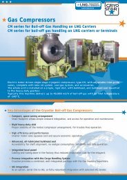
<strong>Cryostar</strong> Training Centre Catalogue<br />
Scheduled sessions performed at <strong>Cryostar</strong> Training Centre, from January to July 2010:<br />
Jan. Feb. March April May June July<br />
Reciprocating pumps -<br />
Industrial Gases<br />
Reciprocating pumps -<br />
Process Application<br />
week 8<br />
23-25 Feb<br />
week 8<br />
23-25 Feb<br />
week 24<br />
7-11 June<br />
week 24<br />
7-11 June<br />
Centrifugal pumps -<br />
Industrial Gases<br />
Centrifugal pumps -<br />
Process Application<br />
week 4<br />
26-28 Jan<br />
week 4<br />
26-28 Jan<br />
week 18<br />
4-6 May<br />
week 18<br />
4-6 May<br />
TEOB - ECO : Turbo Expander<br />
Oil Bearings - ECO<br />
TEOB - TP : Turbo Expander<br />
Oil Bearings - TP<br />
Compressor loaded expansion<br />
<strong>turbine</strong> - TC<br />
week 11<br />
15-19 March<br />
week 11<br />
15-19 March<br />
week 28<br />
5-9 July<br />
week 28<br />
5-9 July<br />
Turbo expander Magnetic<br />
bearing - MTC<br />
week 17<br />
19-23 April<br />
Other courses (see course chart<br />
on www.cryostar.com)<br />
O N<br />
R E Q U E S T<br />
Specific inquiry O N R E Q U E S T<br />
Autumn 2009 11
© <strong>Cryostar</strong> - all rights reserved<br />
Contact: magazine@cryostar.com<br />
www.cryostar.com