The Cryostar Magazine N°3 : pdf file
The Cryostar Magazine N°3 : pdf file
The Cryostar Magazine N°3 : pdf file
- No tags were found...

Create successful ePaper yourself
Turn your PDF publications into a flip-book with our unique Google optimized e-Paper software.
N°3Spring 2004Clean electricityDo expansion turbineshold the key?Breakthrough!<strong>The</strong> latest inliquid O 2 partscleaning technology<strong>The</strong> futurehere todayNew propulsionconcepts forLNG carriers
EDITOWelcome to CRYOSTAR <strong>Magazine</strong>. This, the third edition, looks toprovide a taste of some of the new developments <strong>Cryostar</strong> has introducedto the Energy sector.<strong>Cryostar</strong>, predominantly a solutions provider to the industrial gasesmarket, has over the last 40 years invested in research and developmentto meet the needs of many niche markets, such as LNG and hydrocarbonturbo expanders.By applying this experience and proven technology, Croystar has developednew applications – in particular the Energy Recovery expansionturbine, recently commissioned in a natural gas pressure let down stationin Switzerland.<strong>The</strong> liquid turbines described in the feature on page 10 also provideadded value options. Customers can choose to reduce main compressorenergy costs or produce more with the same amount of energy input.Clean energy production has a great future in all industrialised countriesand <strong>Cryostar</strong>, a supplier of leading edge technology, constantly looks topioneer applications for that technology.In line with that commitment, <strong>Cryostar</strong> has developed solutions inresponse to several processes presently being considered in the energymarket place.And the synergies realised between the demand for high performanceequipment and <strong>Cryostar</strong> technology clearly demonstrate we are at theforefront of innovative and eco-friendly energy handling and recovery.I hope you enjoy this edition.Daniel MEYERManaging DirectorEnergy Recovery with <strong>Cryostar</strong> - TurbinesBreakthrough for liquid O 2 cleaningBelgian filling stations renewal performedby <strong>Cryostar</strong> AutomationLNG transport - the future here todayNewsLiquid turbine generates growthEventsTools and datasp 03p 06p 07p 08p 09p 10p 11p 112Spring 2004
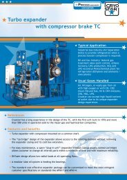
Energy-Recovery with<strong>Cryostar</strong> - TurbinesProducing clean energy is the way of the future. Through the use of expansion turbinesin natural gas pressure let down stations, <strong>Cryostar</strong> combines the growing demand fornatural gas fuel with production of clean, ‘green’, electricity.Clean Energy-Production andEnergy-Recovery (ER) havebeen high on the agenda of theenergy sector for many years.<strong>Cryostar</strong> realised the advantagesof ER early on, and since 1985has been developing expansionturbines for such applications.<strong>The</strong> first ER-unit with a<strong>Cryostar</strong> turbine was installedat Ravenna, Italy, in 1987, withan output of 1,400 kW.Since then, ER-units havebeen operating successfully inItaly, Germany and the Netherlands.<strong>The</strong> latest, and mostmodern unit utilising <strong>Cryostar</strong>technology, was commissionedin Arlesheim, Switzerland, forthe gas utility company GasverbundMittelland AG (GVM).<strong>The</strong> installed power is 3,050kW, with electricity productionstanding at about 18,000 MWhper year. Output is produced byone <strong>Cryostar</strong> expansion turbineTechnical Data of the PlantP r e s s u r e d r o p o f t h e natural gas :M a x . t h r o u g h - p u t o f t h e natural gas :A n nual elec t r i c p o w e r p r o d u c t i o n :T h e r m a l e f f i c i e n c y : 85%Tu r b i n e e f f i c i e n c y : 81%El e c t r i c a l p o w e r o f t h e t u r b i n e :El e c t r i c a l p o w e r o f t h e t w o B H K W s :Tot a l e l e c t r i c a l p o w e r :S u p p l y v o l t a g e i nto the net w o r k :and two block-type thermalpower stations (BHKW) fromJenbacher, and will run at fullpower for about 5,000 hours peryear. <strong>The</strong> general planning ofthe Arlesheim site was done bySwiss engineering firm, Eicher +Pauli AG.4 0 to 55 b a r35,0 0 0 N m 3 / h18 , 0 0 0 M W h1, 8 0 0 k W2 x 6 25 k W3, 0 5 0 k W13 k VSpring 2004 3
ENERGY-RECOVERY<strong>The</strong> reaction turbine is of a radial type and theconstruction is based on a proven design for easymaintenance. But the use of a synchronous generatoris new in the energy recovery business.Previously, asynchronous generators were favouredpurely for simplicity of use. But, in comparison,the combination of a synchronous generator andexpansion turbine produces no reactive current,drastically elevating the ER-unit’s profitability.Such ER-units utilise the potential energy of naturalgas being delivered under high-pressure. <strong>The</strong>gas is only expanded when it reaches the pressurelet down station, and it is here ER-units come intotheir own.To reduce the gas pipeline pressure of 55-bar tomeet the low pressure of 5.5-bar of the local gasdistribution networks, a pressure drop is needed.In other words, the gas is allowed to expand andduring this process drives the <strong>Cryostar</strong> turbinewithin the ER-unit.<strong>The</strong> resulting electricity recovered in this way isthen supplied to local electricity suppliers. <strong>The</strong>efficiency of these units is about 85 per cent, vastlysuperior value when compared to BHKWs, to gasandsteam-turbines or even fuel cells.<strong>The</strong> new ER-unit in Arlesheim is quite revolutionary.It uses a two-stage expansion turbine,equipped with a synchronous generator, to ensureeach stage produces the same power.It allows 35,000 Nm3/h of natural gas to expandfrom 55-bar to 5.5-bar at full capacity, generating1,800 kW. <strong>The</strong> expanded gas volume canalso be reduced in summer time from 35,000 to15,000 Nm3/h, and the inlet pressure of 55-barcan decrease to 30-bar on very cold days.<strong>The</strong> turbine system consists of the dual stageexpansion turbine, a turbo-gearbox, low speedcoupling and the synchronous generator. <strong>The</strong> wholeunit, including the seal gas and lube oil system ismounted on a rigid base frame.And for simplicity of use, control of the turbine andthe auxiliary systems is performed by a programmablelogic controller (PLC). <strong>The</strong> PLC controlsa constant outlet pressure (pressure control) ora constant gas flow (flow control) through theturbine.In other words, under pressure control, the outletpressure is adjusted to a set point by opening orclosing of the adjustable inlet nozzles. In turn, thegas flow through the turbine will change so thatthe actual downstream gas pressure will adjust tothe set point. In case of flow control, the adjustableinlet nozzles will supply a constant flow, and willbe opened or closed only by higher or lower flowdemand.To use the energy for the new ER-unit in the mostefficient way, all heating losses (waste heat ofall auxiliary systems) is recycled to preheat thenatural gas. <strong>The</strong>refore the ER-unit is equipped notonly with a high temperature heating system, butalso with a low temperature heating system. Thisrecycles all heat losses from the turbine coolersand BHKW’s exhaust gases. Each turbine stage isequipped with a preheater fed by the low temperatureheating system and with a second preheater fedby the high temperature heating system. This heatsthe natural gas up to 30ºC (LT system) respectivelyup to 78ºC (HT system).Where a plant operates in low-flow conditions, thehigh temperature heating system is fed from theBHKWs, At high-flow it is fed from the BHKWsin combination with the existing heating boilers,which also supply the heating system of an adjacentoffice building.4Spring 2004
ENERGY-RECOVERY<strong>The</strong> electricity from the synchronous generators(BHKW 400V, Turbine 6.3kV) is fed into the electricitygrid and delivered to local consumers. Forthis the expansion turbine as well as the BHKW’sare equipped with a transformer.<strong>The</strong> whole plant is controlled by a master PLC,which sends all necessary information fordispatching. It operates in separate system groups,and each group is equipped with a PLC (slave) tocontrol their own auxiliary system. This arrangementallows independent operation of each group,and gives better plant redundancy.<strong>The</strong> big advantage of ER-units is that they supplyabsolutely clean energy, and therefore fulfil allregulations regarding environmental protection.ER-units are not only more efficient and profitablebut meet the environmental criteria – no emissionsof sulphur dioxide, nitrogen oxide or carbondioxide.And even though the investment in such plant isrelatively high, demand is increasing year-on-year.This mirrors the increasing pressure on the energygeneration sector to produce clean, environmentally-friendly,electricity.Use of natural gas is a step in this direction and,with reasonable reserves available worldwide,looks to have a bright future.Certainly no one can afford to ignore the shorttermvalue of coal and oil to produce energy, butthe production of clean electrical power is growingin importance.Already, where possible, many household consumersand trade and industry companies are movingto heating by natural gas instead of coal or oil. <strong>The</strong>reasons are simple: not only is it ‘greener’ thancoal/oil but it’s cheaper.<strong>The</strong> market is also shifting towards designingER-plants on a smaller scale for villages and smalltowns.And, timely investment in research and developmentmeans <strong>Cryostar</strong> already has the technologies– solutions like expansion turbines with magneticbearings and/or high frequency generators – toservice this new sector.Spring 2004 5
LIQUID O 2CLEANINGBreakthrough for liquid O 2 cleaningS afet y i s C r yo s t a r . . . t h e r e i s n o o t h e r way t o d o b u s i n e s s , b e i t i nternallyt hrough b e s t o p e rating p ra c t i c e s o r ex t e r n a lly, a p p l y i n g t h e s a m e s afet yp r i n c i p l e s t o t h e b e n e f i t of c u s t o m e r s . N o t hing i s m o r e i m p o r t a nt t h a n g u a r -a nteeing t h a t a ll p a r t s a n d m a c hines u s e d i n liquid ox yg e n o p e rations a r et o t a lly degreased.<strong>Cryostar</strong> is using an innovative solution forcleaning liquid oxygen process machinery.<strong>The</strong> technology, a result of two years research anddevelopment, utilises an automatic closed-chamberprocess based on chlorinated hydrocarbons as thecleaning agent.<strong>The</strong> development of the new system means the gasesindustry is assured that all <strong>Cryostar</strong> machinery andspare parts for processing liquid oxygen are totallydegreased – negating the risk of catastrophic failurewhen the unit/parts come into contact with liquidoxygen.<strong>The</strong> methodology behind <strong>Cryostar</strong>’s new technologyconsists of a cleaning and a drying process in a hermetically-sealed,closed work chamber, managed byan automatic control system to maximise efficiency.All parameters such as pressure, temperature andtime are governed by predetermined settings withinthe control system’s programmes. Operator interfaceis strictly limited.<strong>The</strong> system also permits rotation and swivel movementsduring both the cleaning and the drying phases.Cleaning efficiency is further enhanced through theuse of ultrasonics and an ingenious, patented, airflowdisplacement process.<strong>The</strong> system continuously re-treats the cleaningagent via an integrated vacuum distillation, waterseparation and residual distillation unit that limitsconsumption while guaranteeing efficiency.Each week the solvent pH, alkalinity acceptance andacidity acceptance checks are carried out to ensureproduct quality and avoid any risk of deviation tothe cleaning acceptance criteria. <strong>The</strong> whole processguarantees total degreasing of parts.To date excellent results have been achieved forvarious materials with different degrees of soiling.<strong>The</strong> design has also proved to be very user-friendlyand is in line with industry safety and environmentalprotection standards.N O T Eu n d e r C r y o s t a r ’s s t r i c t h e a l t h a n ds a f e t y a n d b e s t o p e r a t i n g p r a c t i c er u l e s , a l l p a r t s c l e a n e d – r e g a r d l e s s o fe n d - u s e – a r e s u b j e c t t o r i d g e d q u a l i t yc o n t r o l w i p e t e s t s o r b l a c k l i g h t t e s t s .S i m i l a r l y, a l l s p a r e p a r t s d e s i g n e dt o c o m e i n t o c o n t a c t w i t h l i q u i do x y g e n a r e a u t o m a t i c a l l y d e g r e a s e da n d t h e n v a c u u m - s e a l e d i n p l a s t i c b a g st h a t a r e m a r k e d w i t h t h e O 2c l e a n i n gm e n t i o n . .6Spring 2004
BUSINESS CENTRESBelgian filling stations renewalperformed by <strong>Cryostar</strong> AutomationIn the first quarter of 2003, <strong>Cryostar</strong> Automationwas approached by independent Belgian gas supplier,IJS Fabriek Strombeek, to fully modernise itsturn-of-the-century installation.<strong>The</strong> customer was in search of solutions to providegreater efficiency and traceability, and softwaretechnology to enable precise production managementcontrol.After the initial assessment phase, Automationidentified the need to replace electrical cabinets,based on small PCs, Elintec input/output cards andTSX17 PLC, with <strong>Cryostar</strong> standard cabinets basedon SIEMENS and Profibus technology.<strong>Cryostar</strong> engineers opted, for the most part, torecycle the mechanics and kept the fully equipped,steel frame, valves and electrical cabinets. However,filling modules were added to enable the multitaskcapability.<strong>The</strong> greater part of the challenge was to replaceeverything without any loss of production.<strong>Cryostar</strong> Automation engineers achieved thisthrough the use of ‘configuration software’ to adaptthe new management programme to the existingconfiguration. <strong>The</strong>y also initiated a programme ofrigorous mechanical, electrical and software testingat the <strong>Cryostar</strong> factory test facility.<strong>The</strong> outcome was <strong>Cryostar</strong> Automation solutionsprovided many new capabilities to IJS FabriekStromBeek’s installation, but above all the entiredesign was achieved with <strong>Cryostar</strong>’s main priority inmind – safety.<strong>Cryostar</strong> secured the safety of operators throughthree redundant levels – electrical, mechanical andsoftware. Plus, the software system is also secured bylimiting access to password and log-in.This is further enhanced by designating a certainlevel of access to individual operators, ensuring thesystem provides the rightinformation to the right person.Further more, there is apermanent check between thetechnical configuration of thefilling systems – through thesupervision PC – and the actionsselected by the operator.Thus negating ‘human error’as a source of fault.<strong>The</strong> filling station reconstruction was completedduring the summer of 2003 and to ensure ongoingsupport – first level assistance – a permanent link viamodem exists to <strong>Cryostar</strong> engineers.<strong>Cryostar</strong> configuration<strong>The</strong> new plant installed for IJS Fabriek Strombeekincludes:> four Systems including: Monogas filling systems(N 2O, CO 2, O 2,) and mixtures systems (CO 2,O 2, Ar, N 2and He). <strong>The</strong>se systems are fillingindustrial and medical gases. Each system has itsown interface;> five vacuum pumps;> seven cryogenic pumps;> one Supervision PC; and> five wireless barcode readers.<strong>Cryostar</strong> added valueSome of the new capabilities brought to IJS FabriekStrombeek’s process are:> multitask facility;> synchronisation function to minimise the gaslosses and therefore increase the productivity;> barcode traceability (filling and delivery process);> supervision software;> production reports software: results, time date,time spent;> maintenance support software: preventive andcurative, traceability of the defaults; and> link with existing AS400 software that controls thewhole fill plant (filling and delivery traceability,work orders).Spring 2004 7
LNG TRANSPORTusing the counter-current plate fin heat exchangerto bring the gas back to ambient temperature andallow compressor suction. <strong>The</strong> three-stage compressorand the expansion turbine are combined asa compander on a common gearbox.EcoChill vs. EcoRelIn simple terms, with EcoChill the boil-off gasvapour does not need to be compressed forreliquefaction. In comparison, the boil-off gascompression energy for EcoRel requires a 20per cent higher energy input to the Braytoncycle, than with the EcoChill without the gascompression.EcoChill also has the added advantage that boiloffgas compressors can be avoided altogether.Instead, compression power is replaced inEcoChill by the very low pumping power forLNG re-circulation in the sub-cooling cycle.<strong>The</strong> result is that the heat in-leak compensationfunction of EcoRel with, for example, 5,000kWtotal input power (this being the typical powerrequirement for 200 to 250,000m3 LNGC) canbe achieved by EcoChill using only 4,000 kW.<strong>The</strong> 1,000kW difference corresponds to US$12-14million in fuel cost savings during the 40-year lifeof an LNGC. Plus, the investment cost for EcoChillis slightly lower again.Leading edge<strong>Cryostar</strong> products for the current cargo handlingsystem for LNGC’s with Steam Turbine Propulsionare single stage boil-off gas and warm-up compressors,gas heaters and vaporisers. <strong>Cryostar</strong>’s rangewas extended during 2003 to include mediumpressure two-stage boil-off gas compressors forLNGC’s with Diesel-Electric Propulsion. In linewith <strong>Cryostar</strong>’s commitment to leading edge oftechnology, it now offers four-stage boil-off gascompressors with up to 40-bar discharge pressurefor LNGCs using Gas Turbine Propulsion.Patent protection: <strong>The</strong> <strong>Cryostar</strong> intellectual propertiesfor both the EcoRel and EcoChill principles areprotected by patent<strong>The</strong> new propulsion concepts for future LNG Carrierswere described extensively in <strong>Cryostar</strong> magazine Spring2003 issueNews<strong>Cryostar</strong> France investment<strong>Cryostar</strong> France is investing in an additional 300m 2of floor space to meet the growing needs of itsengineering section.New propulsion system delivered<strong>Cryostar</strong> delivered the world’s first two-stageboil-off gas compressors to France’s Chantier deL’Atlantique in January for its first LNG carrier usingDiesel-electric propulsion.Central bank rates <strong>Cryostar</strong> tops!<strong>The</strong> French central bank, Banque de France, hasawarded <strong>Cryostar</strong> with its top financial ratings.For the third year in a row, <strong>Cryostar</strong> has achieved acredit rating of three, and scored seven for paymentsperformance. NB: A rating of ‘three’ reflects thehighest level of excellence that can be awarded tocompanies in terms of quality of credit and ability tofully honour financial commitments. A ‘seven’ ratingis the highest indicator that payments are madeon a regular basis and that the company has neverexperienced payment incidents.Spring 2004 9
LIQUID TURBINELiquid turbine generates growthdesign features of a liquid turbine includedouble sealing philosophy, careful coldbarrier design and a comprehensive monitoringof crucial machine parameters.It all started in 1983 when <strong>Cryostar</strong>commissioned its first liquid turbine forthe BOC Widness plant. This first liquidturbine was based on a Pelton wheel designand its isentropic efficiency level wasbetween 33-36 per cent.Soon afterwards a Francis wheel replacedthe Pelton wheel and efficiency levelssoared to values higher than 70 per centwith a liquid turbine that was commissionedfor BOC Scunthorpe in 1986.growing number of <strong>Cryostar</strong> customers areA opting for the ‘liquid turbine’ in combinationwith a conventional expander-generator orexpander-compressor unit. And with reportedpower savings of more than 500 kW and flexibilityof use, this comes as no surprise.Liquid turbines can be used in most of the liquefactioncycles (air separation, nitrogen liquefaction,LNG liquefaction, hydrocarbon processes, etc.).<strong>The</strong>y are installed in parallel to the Joule-Thompsonvalve and are supposed to replace them duringthe operation of the plant.<strong>The</strong> growing popularity of the liquid turbine, thelatest addition to rotating machinery for industrialgas plants, is another example of <strong>Cryostar</strong>’s commitmentto research and development in order toprovide innovative engineering solutions.Over the years, <strong>Cryostar</strong> engineers conducteda number of design studies in order to satisfystringent customer requirements. <strong>The</strong> resultingWhat followed was a minute fine-tuning ofthis prototype over the next decade untilthe liquid turbine reached its technicalmaturity.In 1999, for the first time in its history, a liquidturbine – due to be commissioned for Air Liquide– underwent a full-load, full-pressure test at<strong>Cryostar</strong>’s unique cryogenic test facility in France.<strong>The</strong> results were more than satisfactory – theturbine reached isentropic efficiencies of up to 84per cent.Since then, liquid turbines have become standardequipment installed in air separation plants and<strong>Cryostar</strong> has seen many customers including thesein new plants, but also in existing plants since thepay back is so short!10Spring 2004
EVENTS & TOOLSEventsApril 27-30, 2004CRYOGENICS 2004 and CRYO-MARKET 2004, ExhibitionPraha, Prague, Czech Republic.May 11-14, 200420th International CryogenicEngineering Conference (ICEC20), Beijing, China.May 18-20, 20044th Annual World GTL Summit2004, London, UK.May 27-28, 2004LNG North Am Summit, Houston,Texas, USA.September 22-14, 2004Energie 2004, Avignon, France.October 26-28, 2004NGV 2004, Buenos Aires,Argentina.For more details:www.ngv2004.comTools and datas:Carbon Dioxide Conversion DataWe have decided to dedicate this section of our magazine to include usefull tools and datas that are handy in ourindustry. In this issue, the Carbon Dioxide Conversion Data table.Weight Gas Liquid SolidPounds(Lb)Kilograms(KG)Cubic Feet(SCF)Cubic Meters(Nm 3 )Gallons(Gal)Liters(L)Cubic Feet(CuFt)Cubic Meters(m 3 )1 Pound 1.000000 0.453592 8.741500 0.229427 0.118149 0.447242 0.010246 0.0002901 Kilogram 2.204622 1.000000 19.271707 0.505800 0.260474 0.986000 0.022589 0.0006401 SCF Gas 0.114397 0.051890 1.000000 0.026285 0.013516 0.051163 0.001172 0.0000331 Nm 3 Gas 4.358684 1.977066 38.044053 1.000000 0.514974 1.949387 0.044659 0.0012651 Gal Liquid 8.463899 3.839160 73.987173 1.941847 1.000000 3.785412 0.086721 0.0024561 L Liquid 2.235925 1.014199 19.545342 0.512982 0.264172 1.000000 0.022909 0.0006491 CuFt Solid 97.599063 44.270193 853.162212 22.391862 11.531218 43.650411 1.000000 0.0283171 m 3 Solid 3446.677978 1563.386936 30129.135546 790.761062 407.221068 1541.499516 35.314662 1.000000SCF (Standard Cubic Foot) gas measured at 1 atmosphere and 70°F.Liquid measured at 21.42 atmospheres and 1.7°F.Solid measured at -109.25°FNm3 (normal cubic meter) gas measured at 1 atmosphere and 0°C.All values rounded to nearest 4/5 significant numbers.Spring 2004 11
© CRYOSTAR - all rights reservedContact: magazine@cryostar.comwww.cryostar.com