Birkett Technical Catalogue - Safety Systems UK Ltd
Birkett Technical Catalogue - Safety Systems UK Ltd
Birkett Technical Catalogue - Safety Systems UK Ltd

You also want an ePaper? Increase the reach of your titles
YUMPU automatically turns print PDFs into web optimized ePapers that Google loves.
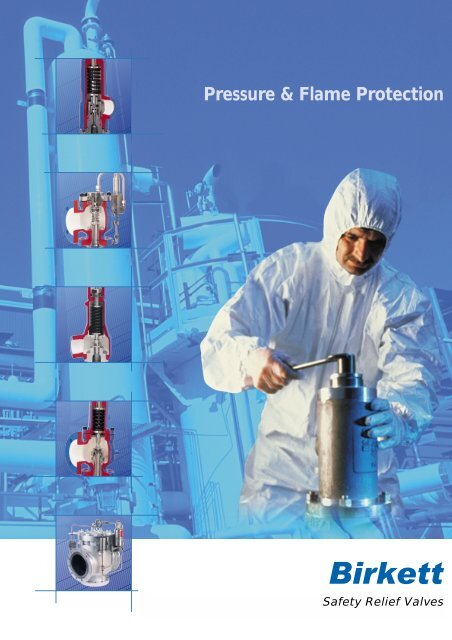
Pressure & Flame Protection<br />
<strong>Safety</strong> Relief Valves
<strong>Safety</strong> Relief Valves<br />
‘WB’ SERIES SPRING LOADED<br />
SAFETY RELIEF VALVES<br />
The WB is designed to safely relieve excess pressure in<br />
pumps, pipework, tanks, calorifiers, gas and oil<br />
separators and other process vessels. It is suitable for<br />
gas, steam, vapour and liquid applications. The WB<br />
conforms to API 526 pressure/temperature ranges,<br />
orifice areas and dimensions.<br />
‘SAFEFLO’ SAFETY AND<br />
THERMAL RELIEF VALVES<br />
Safeflo valves are designed for similar duties to the WB<br />
but for small capacity applications.They safely relieve<br />
thermal expansion of process fluids in vessels and long<br />
lengths of pipework, and are suitable for gas and liquid<br />
applications.<br />
‘SAFESET’ PILOT OPERATED<br />
SAFETY RELIEF VALVES<br />
Safeset valves are self contained pilot operated safety<br />
relief valves which use the system pressure to control<br />
the valve opening and closing. No other source of<br />
energy is required.<br />
A choice of different types of Safeset pilot valves are<br />
available, including pop and modulating action to suit a<br />
variety of applications.<br />
1<br />
Safeset valves conform to API 526 pilot operated<br />
pressure/temperature ranges and dimensions, with<br />
multiple orifice areas contained within each valve<br />
body size.
CONTENTS<br />
Page<br />
<strong>Birkett</strong> Range<br />
3 Introduction<br />
4 International approvals and authorisations<br />
5 WB Series<br />
6 Features and benefits<br />
7 - 10 Valve types and action<br />
11 - 14 Drawings<br />
15 - 16 Accessories<br />
17 Figure numbering system<br />
18 Material temperature ranges<br />
19 - 46 Valve selection charts, D to T<br />
47 - 48 Valve adjustment<br />
49 - 50 Seat tightness/seat leakage testing<br />
Page<br />
Sizing<br />
81 - 82 Sizing formula<br />
83 Nomenclature<br />
84 Back pressure/blowdown limits and<br />
orifice areas<br />
85 - 90 Sizing factors<br />
91 - 96 Capacity charts<br />
97 Reaction forces<br />
98 Definitions<br />
98 Definitions of terms<br />
99 Operational characteristics<br />
100 Pressure term relationships<br />
51 Safeflo<br />
52 Features and benefits<br />
53 - 54 Drawings<br />
55 Accessories<br />
56 Figure numbering system<br />
57 - 58 Dimensions<br />
59 Safeset<br />
60 Features and benefits<br />
61 Dual Outlet/Full Bore Pilot Valve<br />
62 Pilot types and basic operation<br />
63 - 64 Type 2 - Pop Action Pilot<br />
65 - 68 Type 4 and 8 - Modulating Action Pilot<br />
69 <strong>Technical</strong> specification<br />
69 - 70 Drawings and materials of construction<br />
71 - 75 Accessories<br />
76 Figure numbering system<br />
77 - 78 Dimensions<br />
79 - 80 Operating pressure/temperature limits<br />
2
<strong>Safety</strong> Relief Valves<br />
INTRODUCTION<br />
The effects of exceeding safe pressure levels in an<br />
unprotected pressure vessel or system can have<br />
catastrophic effects on both plant and personnel.<br />
<strong>Safety</strong> relief valves should be used to protect any<br />
pressurised system from the effects of exceeding its<br />
design pressure limit.<br />
A safety relief valve is designed to automatically<br />
discharge gas, steam, vapour or liquid from any<br />
pressure containing system, preventing a<br />
predetermined safe pressure being exceeded, and<br />
protecting plant and personnel.<br />
The <strong>Birkett</strong> range of safety relief valves<br />
contains three distinct valve types:<br />
WB Series – spring loaded safety relief valves.<br />
Safeflo – safety and thermal relief valves.<br />
Safeset – pilot operated safety relief valves.<br />
All types are certified in accordance<br />
with ASME Code Section VIII.<br />
All <strong>Birkett</strong> valves are available through our global<br />
agent distribution network supported by our own<br />
regional sales offices around the world.<br />
3
INTERNATIONAL APPROVALS AND AUTHORISATIONS<br />
Our approvals and accreditations<br />
include ISO 9001:2008, ASME,<br />
Chinese <strong>Safety</strong> Quality Licence,<br />
TUV, Bureau Veritas,<br />
Stoomwezen, PED, ATEX and<br />
GOST-R.<br />
APPLICABLE STANDARDS<br />
ISO 9001:2008<br />
Quality Standard<br />
ASME Code Section VIII<br />
All valves are UV certified<br />
API 520 : Part 1<br />
Sizing and selection<br />
API 526<br />
Dimensions<br />
API 527<br />
Leakage Rates<br />
ANSI B16.5<br />
Flange Ratings<br />
4
WB Series -<br />
Spring loaded safety relief valve<br />
1 Insitu testing<br />
2 Accessories<br />
3 High performance springs<br />
4 Bellows back up piston<br />
(not shown)<br />
5 Guiding<br />
6 Bellows<br />
(not shown)<br />
7 Trim<br />
8 Seat integrity<br />
9 Adjustable blow down<br />
10 Nozzle design<br />
11 API 526 face to face<br />
dimensions<br />
5
FEATURES AND BENEFITS<br />
Design verification – all design options and the<br />
various effects of system conditions, back pressure<br />
etc. have been verified on <strong>Birkett</strong>’s<br />
in-house, extensive mass flow test facility.<br />
Lighter and more compact construction –<br />
continuous design improvements have created<br />
smaller and lighter valves to support current<br />
industry design trends, especially space and weight<br />
savings.<br />
Interchangeable parts – valves can be modified<br />
from type to type, gas, liquid, conventional and<br />
bellows simply by changing only a few parts.<br />
Simplified maintenance and service -<br />
re-engineering has reduced the number of parts,<br />
making maintenance easier and more cost<br />
effective.<br />
Material selection – a wide range of materials<br />
are offered including non-ferrous for low<br />
temperature and oxygen service, as well as exotic<br />
alloys specifically for the chemical and process<br />
industries.<br />
Cryogenic and oxygen service – <strong>Birkett</strong>’s<br />
state-of-the-art clean room and vapour degreasing<br />
facilities ensure compliance with the stringent<br />
demands of cryogenic and oxygen applications.<br />
1 In-situ testing – valves can be supplied<br />
suitable for application of “in-situ” set<br />
pressure verification devices.<br />
2 Wide range of accessories – available to<br />
comply with international codes and to suit<br />
system requirements.<br />
3 High performance springs – safety relief<br />
valve springs are specifically designed to<br />
guarantee set point repeatability.<br />
4 Bellows back-up piston – an optional<br />
auxiliary back-up piston for balanced bellows<br />
valves ensures fail-safe operation in the event<br />
of bellows failure (see page 16).<br />
5 Guiding surfaces – the material selection of<br />
guiding components, together with a selfaligning<br />
disc and spindle pivot point, ensures<br />
correct alignment and no galling of guiding<br />
surfaces.<br />
6 Bellows – ensures correct valve<br />
performance under difficult back pressure<br />
conditions (see page 12).<br />
7 Trim – specific gas and liquid trim designs<br />
give stable operation and eliminate the<br />
damaging effect of chatter.<br />
8 Seat leakage integrity – choice of nozzle<br />
and disc materials (coupled with superior<br />
lapping techniques) provides seat tightness to<br />
API 527/ASME VIII.<br />
9 Adjustable blow down – the valve<br />
reseating pressure (blow down) can be simply<br />
adjusted to suit special or specific<br />
performance requirements.<br />
10 Nozzle design – the method and location of<br />
attachment to the body avoids transmission<br />
of pipe stresses to the nozzle/disc mating<br />
surfaces.<br />
11 API 526 dimensions – standardised<br />
dimensions allows pipework layouts to be<br />
detailed confidently.<br />
6
DIFFERENT TYPES<br />
There are four basic types of WB Series safety<br />
relief valve:<br />
WB400 – conventional gas type.<br />
WB300 – bellows gas type.<br />
WB200 – conventional liquid type.<br />
WB100 – bellows liquid type.<br />
Conventional safety relief valves:<br />
Can be used on systems where the discharge is<br />
relatively simple. The pressure in the discharge<br />
system can be atmospheric, at a constant level or<br />
where the pressure may build up to a maximum of<br />
10% of the set pressure. When a constant back<br />
pressure exists, the valve should be set at the<br />
differential pressure (refer to page 8).<br />
Liquid service<br />
Valves operating on liquid service require a<br />
modified valve design to cope with the differing<br />
dynamics of liquid flow.<br />
A contoured plug disc is used to minimise initial<br />
flow rate, eliminating any potential inlet pressure<br />
drops due to excessive valve lift. The valve will<br />
simmer until sufficient pressure is available to<br />
generate lift. Once this has occurred, the lift will<br />
stabilise to suit the flow and pressure conditions<br />
required, thus avoiding the problem of chatter.<br />
‘Chatter’ is the rapid opening and closing of the<br />
valve which can have a damaging effect on the disc<br />
and nozzle, causing it to leak.<br />
Bellows safety relief valves:<br />
The WB Bellows Valves are statically balanced and<br />
can be used on more complex discharge systems<br />
such as common discharge manifolds and flares<br />
where several valves may discharge. This type of<br />
system creates a variable superimposed back<br />
pressure. The balanced bellows unit cancels out<br />
the effects of variable back pressure, on the set<br />
pressure of the safety relief valve.<br />
Gas and vapour service:<br />
The gas/vapour disc can be distinguished by the flat<br />
underside, unlike the cone profile of the liquid disc.<br />
Typical liquid relief valve disc<br />
7
THE EFFECT OF BACK PRESSURE<br />
The configuration of a closed discharge pipework<br />
system, typically for toxic or hazardous duty, can<br />
generate back pressure. Back pressure applied to<br />
the outlet of the valve will adversely affect its<br />
performance, unless it is addressed.<br />
Back pressure may take three forms:<br />
1. Superimposed constant back pressure<br />
This exists permanently and a conventional or<br />
bellows valve can be used. A conventional valve<br />
can be set at the differential pressure so that the<br />
spring load is adjusted to take account of the back<br />
pressure.<br />
2. Built up back pressure<br />
Built up back pressure is created by the<br />
configuration of discharge pipework systems and<br />
varies from zero when the valve is closed, to a<br />
maximum, when fully open. Conventional spring<br />
loaded valves can tolerate up to 10% of set<br />
pressure as built up back pressure. For back<br />
pressures in excess of 10%, a balanced bellows<br />
design is required to maintain valve lift.<br />
3. Superimposed variable back pressure<br />
This is caused by other valves discharging into a<br />
common disposal system, or other circumstances<br />
that cause the back pressure to be variable.<br />
Balanced bellows valves should be used for this<br />
condition, adjusted to the predetermined set<br />
pressure.<br />
Constant back pressure - conventional valve<br />
Variable back pressure - balanced bellows valve<br />
8
VALVE ACTION<br />
Principles of operation – spring loaded<br />
safety and thermal relief valves<br />
SPRING FORCE<br />
<strong>Safety</strong> relief valves use a spring force to hold a disc<br />
against a nozzle. Under normal system operating<br />
pressure, the valve will remain closed as the spring<br />
force is greater than the inlet system pressure<br />
force. The valve opens when the system pressure<br />
force becomes greater than the closing force of<br />
the spring.<br />
Spring loaded safety and thermal relief valve<br />
The WB and B/C series are designed to have a<br />
short simmer, open rapidly to full lift position and<br />
then re-seat at a controlled shut off pressure.<br />
This is demonstrated in the graph below, which<br />
shows the valve action and corresponding pressure<br />
at the valve inlet.<br />
SYSTEM PRESSURE FORCE<br />
POPPING PRESSURE<br />
SET PRESSURE<br />
RE-SEAT PRESSURE<br />
Popping and blowdown<br />
The opening and closing characteristics of the valve<br />
can be controlled by the adjustment of a<br />
blowdown ring, as its position affects the shape<br />
and volume of the huddling chamber. When the<br />
blowdown ring is adjusted to its top position, the<br />
exit area from the huddling chamber is restricted<br />
to its minimum. The valve will pop distinctly with a<br />
short simmer and long blowdown. Conversely,<br />
when the blowdown ring is in its lowest position<br />
there is a maximum exit area from the huddling<br />
chamber and the valve will have a longer simmer<br />
with a shorter blowdown. The blowdown ring can<br />
be positioned between these two extremes to give<br />
the required performance, but it is usually factory<br />
set to achieve re-seating 7-10% below set pressure.<br />
9
LIFT CYCLE<br />
Stage 1 – Closed<br />
Inlet pressure < set pressure<br />
Inlet pressure is below the set pressure. The valve is<br />
closed and there is no flow through the valve.<br />
Stage 2 – Simmering<br />
Inlet pressure is = > set pressure and < popping pressure<br />
Inlet pressure increases to set pressure. At this point, the spring<br />
force and system pressure force are equal; a further rise in inlet<br />
pressure will then begin to lift the disc slightly. A small amount of<br />
fluid is released into the huddling chamber (the valve simmers).<br />
The system fluid is now acting on a larger area inside the<br />
huddling chamber.<br />
Stage 3 – Popping and opening<br />
Inlet pressure = > popping pressure, valve fully open<br />
The inlet pressure acting on a larger area produces a significant<br />
force to accelerate the opening. A combination of this pressure<br />
force, the kinetic energy from the fluid within the nozzle and the<br />
deflection force of the fluid flow turning through the reaction<br />
hood, is transformed into disc lifting force. The valve pops open<br />
at < 5% overpressure and the valve reaches the full open<br />
position at 110% of set pressure, in accordance with<br />
international codes.<br />
Stage 4 – Reseating<br />
Inlet pressure falls to re-seating pressure<br />
As system pressure starts to fall, the force from the spring<br />
begins to close the valve. Typically, the system pressure falls<br />
between 5-10% below the valve set pressure at which point<br />
the spring force accelerates the valve disc to re-seat the valve.<br />
The difference between the set pressure and the re-seating<br />
pressure is known as blowdown.<br />
10
WB 400 - CONVENTIONAL GAS TYPE<br />
(up to and including class 600)<br />
ITEM PART CARBON STEEL STAINLESS STEEL<br />
1 Body SA 216-WCB CARB ST SA 351-CF8M ST ST<br />
2 Casing SA 216-WCB CARB ST SA 351-CF8M ST ST<br />
3 Cap SA 216-WCB CARB ST SA 351-CF8M ST ST<br />
4* Nozzle 316 ST ST 316 ST ST<br />
5* Disc 316 ST ST 316 ST ST<br />
6* Disc holder ASTM A479-316L ASTM A479-316L<br />
8 Blowdown ring SA 351-CF8M ST ST SA 351-CF8M ST ST<br />
9 Guide Assy CARBON ST/17-4 ST ST 316L/17-4 ST ST<br />
10* Spindle ASTM A479-431 ASTM A479-431<br />
11 Lower spring plate ASTM A108-1021/Ni PLT ASTM A479-431<br />
12 Adjusting screw ASTM A479-410 ASTM A479-410<br />
13 Locking nut ASTM A108-1021 ASTM A479-316L<br />
14 Setting screw ASTM A479-431 ASTM A479-431<br />
15 Setting screw rod ASTM A479-316L ASTM A479-316L<br />
18 Stud SA 193-B7 CR/MOL ST SA 193-B8T ST ST<br />
19 Nut SA 194-2H CARB ST SA 194-8T ST ST<br />
22* Spring CARBON STEEL ASTM A313-316<br />
27* Body gasket ST-706 ST-706<br />
28* Cap gasket ST-706 ST-706<br />
29* Set screw gasket ST-706 ST-706<br />
31* Ball AISI 440C ST ST AISI 440C ST ST<br />
32 Upper spring plate ASTM A108-1021/Ni PLT ASTM A479-431<br />
33 Data plate 321 ST ST 321 ST ST<br />
34 Hammer drive screw ELECTRO BRASSED ST ASTM A479-316L<br />
35 Grooved pin ASTM A479-431 ASTM A479-431<br />
42 Drain plug HTS HOLO-KROME ASTM A479-316L<br />
80* Circlip ASTM A313-316 ASTM A313-316<br />
* Recommended spares<br />
11
WB 300 - BALANCED BELLOWS GAS TYPE<br />
(up to and including class 600)<br />
ITEM PART CARBON STEEL STAINLESS STEEL<br />
1 Body SA 216-WCB CARB ST SA 351-CF8M ST ST<br />
2 Casing SA 216-WCB CARB ST SA 351-CF8M ST ST<br />
3 Cap SA 216-WCB CARB ST SA 351-CF8M ST ST<br />
4* Nozzle 316 ST ST 316 ST ST<br />
5* Disc 316 ST ST 316 ST ST<br />
6* Disc holder INCLUDED IN ITEM 23 INCLUDED IN ITEM 23<br />
8 Blowdown ring SA 351-CF8M ST ST SA 351-CF8M ST ST<br />
9 Guide Assy CARBON ST/17-4 ST ST 316 L/17-4 ST ST<br />
10* Spindle ASTM A479-431 ASTM A479-431<br />
11 Lower spring plate ASTM A108-1021/Ni PLT ASTM A479-431<br />
12 Adjusting screw ASTM A479-410 ASTM A479-410<br />
13 Locking nut ASTM A108-1021 ASTM A479-316L<br />
14 Setting screw ASTM A479-431 ASTM A479-431<br />
15 Set screw rod ASTM A479-316L ASTM A479-316L<br />
18 Stud SA 193-B7 CR/MOL ST SA 193-B8T ST ST<br />
19 Nut SA 194-2H CARB ST SA 194-8T ST ST<br />
22* Spring CARBON STEEL ASTM A313-316<br />
23* Bellows assembly ASTM A479-316L/SA240-316L ASTM A479-316L/SA240-316L<br />
27* Body gasket ST-706 ST-706<br />
28* Cap gasket ST-706 ST-706<br />
29* Set screw gasket ST-706 ST-706<br />
31* Ball AISI 440C ST ST AISI 440C ST ST<br />
32 Upper spring plate ASTM A108-1021/Ni PLT ASTM A479 431<br />
33 Data plate 321 ST ST 321 ST ST<br />
34 Hammer drive screw ELECTRO BRASSED ST ASTM A479-316L<br />
35 Grooved pin ASTM A479-431 ASTM A479-431<br />
42 Drain plug HTS HOLO-KROME ASTM A479-316L<br />
80* Circlip ASTM A313-316 ASTM A313-316<br />
* Recommended spares<br />
12
WB 400 - CONVENTIONAL GAS TYPES<br />
(class 900 and above)<br />
ITEM PART CARBON STEEL STAINLESS STEEL<br />
1 Body SA 216-WCB CARB ST SA 351-CF8M ST ST<br />
2 Casing SA 216-WCB CARB ST SA 351-CF8M ST ST<br />
3 Cap SA 216-WCB CARB ST SA 351-CF8M ST ST<br />
4* Nozzle 316 ST ST 316 ST ST<br />
5* Disc 316 ST ST 316 ST ST<br />
6* Disc holder ASTM A479-316L ASTM A479-316L<br />
7 Reaction hood ASTM A479-431 ASTM A479-431<br />
8 Blowdown ring SA 351-CF8M ST ST SA 351-CF8M ST ST<br />
9 Guide plate 17-4 ST ST 17-4 ST ST<br />
10* Spindle ASTM A479-431 ASTM A479-431<br />
11 Lower spring cap ASTM A108-1021/Ni PLT ASTM A479-431<br />
12 Adjusting screw ASTM A479-410 ASTM A479-410<br />
13 Locking nut ASTM A108-1021 ASTM A479-316L<br />
14 Setting screw ASTM A479-431 ASTM A479-431<br />
15 Setting screw rod ASTM A479-316L ASTM A479-316L<br />
16* Tabwasher BS 1449-304S15 ST ST BS 1449-304S15 ST ST<br />
17* Pinning screw ASTM A479-431 ASTM A479-431<br />
18 Body stud SA 193-B7 CR/MOL ST SA 193-B8T ST ST<br />
19 Body nut SA 194-2H CARB ST SA 194-8T ST ST<br />
20 Casing stud SA 193-B7 CR/MOL ST SA 193-B8T ST ST<br />
21 Casing nut SA 194-2H CARB ST SA 194-8T ST ST<br />
22* Spring CARBON STEEL ASTM A313-316<br />
24* Spindle head ASTM A479-431 ASTM A479-431<br />
27* Body gasket ST-706 ST-706<br />
28* Cap gasket ST-706 ST-706<br />
29* Setting screw gasket ST-706 ST-706<br />
31* Ball AISI 440C ST ST AISI 440C ST ST<br />
32 Upper spring cap ASTM A108-1021/Ni PLT ASTM A479 431<br />
33 Data plate 321 ST ST 321 ST ST<br />
34 Hammer drive screw ELECTRO BRASSED ST ASTM A479-316L<br />
35* Grooved pin ASTM A479-431 ASTM A479-431<br />
42 Drain plug HTS HOLO-KROME ASTM A479-316L<br />
* Recommended spares<br />
13
WB 300 - BALANCED BELLOWS GAS TYPE<br />
(class 900 and above)<br />
ITEM PART CARBON STEEL STAINLESS STEEL<br />
1 Body SA 216-WCB CARB ST SA 351-CF8M ST ST<br />
2 Casing SA 216-WCB CARB ST SA 351-CF8M ST ST<br />
3 Cap SA 216-WCB CARB ST SA 351-CF8M ST ST<br />
4* Nozzle 316 ST ST 316 ST ST<br />
5* Disc 316 ST ST 316 ST ST<br />
6* Disc holder base ASTM A479-321 ASTM A479-321<br />
7 Reaction hood ASTM A479-431 ASTM A479-431<br />
8 Blowdown ring SA 351-CF8M ST ST SA 351-CF8M ST ST<br />
9 Guide plate 17-4 ST ST 17-4 ST ST<br />
10* Spindle ASTM A479-431 ASTM A479-431<br />
11 Lower spring cap ASTM A108-1021/Ni PLT ASTM A479-431<br />
12 Adjusting screw ASTM A479-410 ASTM A479-410<br />
13 Locking nut ASTM A108-1021 ASTM A479-316L<br />
14 Setting screw ASTM A479-431 ASTM A479-431<br />
15 Setting screw rod ASTM A479-316L ASTM A479-316L<br />
16* Tabwasher BS 1449-304S15 ST ST BS 1449-304S15 ST ST<br />
17* Pinning screw ASTM A479-431 ASTM A479-431<br />
18 Body stud SA 193-B7 CR/MOL ST SA 193-B8T ST ST<br />
19 Body nut SA 194-2H CARB ST SA 194-8T ST ST<br />
20 Casing stud SA 193-B7 CR/MOL ST SA 193-B8T ST ST<br />
21 Casing nut SA 194-2H CARB ST SA 194-8T ST ST<br />
22* Spring CARBON STEEL ASTM A313-316<br />
23* Bellows SA240-316L SA240-316L<br />
24* Spindle head ASTM A479-431 ASTM A479-431<br />
25 Piston ASTM A479-431 ASTM A479-431<br />
26 Guide spindle ASTM A479-321 ASTM A479-3431<br />
27* Body gasket ST-706 ST-706<br />
28 Cap gasket ST-706 ST-706<br />
29 Setting screw gasket ST-706 ST-706<br />
31 Ball AISI 440C ST ST AISI 440C ST ST<br />
32 Upper spring cap ASTM A108-1021/Ni PLT ASTM A479 431<br />
33 Data plate 321 ST ST 321 ST ST<br />
34 Hammer drive screw ELECTRO BRASSED ST ASTM A479-316L<br />
35 Grooved pin ASTM A479-431 ASTM A479-431<br />
42 Drain plug HTS HOLO-KROME ASTM A479-316L<br />
50 Grubscrew ASTM A479-321 ASTM A479-321<br />
* Recommended spares<br />
14
ACCESSORIES<br />
Screwed cap<br />
This is the standard option on all valves.<br />
Bolted cap<br />
Option available on the WB Series when required<br />
by the customer or for critical service where<br />
fragile gaskets materials may be fitted.<br />
Open lever*<br />
The open lever assembly is not pressure tight and<br />
is therefore only suitable where vapour can safely<br />
be allowed to escape to atmosphere.<br />
Packed lever*<br />
The design of the packed lever assembly ensures<br />
that leakage does not occur when the valve is open<br />
or when back pressure is present.<br />
*A lift lever can be used to test for correct valve operation where corrosion or deposits could prevent the valve from<br />
opening. They can be used to release foreign particles trapped on the seat and must be fitted when codes dictate.<br />
GAG SCREW<br />
SEALING PLUG<br />
Test gag<br />
The test gag is used to prevent the safety valve<br />
from lifting. This is mainly used when carrying out<br />
a hydrostatic test on the system, during<br />
commissioning.<br />
After testing, the test gag must be removed and<br />
replaced with the sealing plug.<br />
15
FERRULE<br />
Ferrule (government ring)<br />
A ferrule, sometimes known as a government ring,<br />
is a collar fitted beneath the head of the pressure<br />
adjusting screw. Some authorities will require a<br />
ferrule to be fitted to prevent unauthorised interference<br />
with the set pressure.<br />
Soft seat<br />
An O-ring seal offers maximum seat tightness,<br />
over and above that of the standard metal-tometal<br />
seats. A wide range of seal materials are<br />
available including Viton, Nitrile, Kalrez and PTFE.<br />
For high integrity seat leakage, specify soft seat.<br />
Steam jacket<br />
Some process media can solidify or<br />
form crystals if they cool within<br />
the system. The medium within<br />
the valve nozzle is not in the<br />
flow path and thus cooling can<br />
occur. Should the medium<br />
solidify, crystallise, or if<br />
sublimation of vapour<br />
was to occur within<br />
the nozzle, the valve<br />
may not lift.<br />
The steam jacket is<br />
designed to keep the process<br />
medium hot, helping to<br />
maximise plant safety. The steam jacket has both<br />
an inlet and outlet so that low pressure steam can<br />
be passed through the jacket, keeping the valves<br />
hot. This allows the valves to stay operational,<br />
enabling the valve to successfully relieve pressure,<br />
should an overpressure situation occur.<br />
The steam jacket is manufactured out of material<br />
that is compatible with the body of the valve and<br />
the connections to the jacket can either be flanged<br />
or screwed.<br />
Auxiliary back-up piston<br />
In the event of bellows failure, a potentially<br />
dangerous situation can arise. The back pressure<br />
causes an “out-of-balance” situation which may<br />
cause:<br />
1 Increase in set pressure.<br />
2 Decrease in flow capacity.<br />
3 Increase in re-seat pressure.<br />
Specifying bellows valves with an auxiliary back-up<br />
piston ensures that the above does not occur. The<br />
piston itself has the same effective diameter as the<br />
failed bellows, so any effect of the back pressure<br />
increasing the set pressure is counteracted by an<br />
upward thrust of the piston. This is an added<br />
safety feature. The WB 300 valve has<br />
incorporated the auxiliary back-up piston since its<br />
inception. It is available as standard in all pressure<br />
classes 900 and above and as an optional feature<br />
for class 600 and below.<br />
To ensure absolute safety, specify the auxiliary<br />
back-up piston.<br />
16
WB SERIES FIGURE NUMBERING SYSTEM<br />
/<br />
Inlet diameter<br />
1” - 8”<br />
API orifice letter<br />
D - T<br />
Outlet diameter<br />
2” - 10”<br />
Design<br />
H ANSI 150, 300 and 600<br />
/ ANSI 900, 1500 and 2500<br />
Accessories<br />
B Auxiliary<br />
back-up piston<br />
C Bolted cap<br />
D Screwed cap<br />
F Ferrule<br />
(Government ring)<br />
G Test gag<br />
H* High Pressure<br />
M Open lever<br />
P Packed lever<br />
R Soft seat<br />
S Special feature<br />
3 WB300 Bellows<br />
Valve type<br />
1 Liquid bellows<br />
2 Liquid conventional<br />
3 Vapour bellows<br />
4 Vapour conventional<br />
ANSI flange rating inlet x outlet<br />
1 150 x 150<br />
2 300 x 150<br />
3 600 x 150<br />
4 900 x 150<br />
5 900 x 300<br />
6 1500 x 150<br />
7 1500 x 300<br />
8 2500 x 300<br />
O Special<br />
Flange face<br />
1 ANSI RF x RF<br />
2 ANSI RTJ inlet x RF<br />
O Special<br />
Trim material nozzle and disc<br />
1 Stainless steel PH 17/4<br />
2 Stainless steel 316<br />
3 Aluminium bronze / Monel<br />
4 Hastelloy B<br />
5 Stainless steel 316 stellited<br />
6 Monel<br />
7 Stainless steel 304<br />
O Special<br />
Spring material<br />
1 Carbon steel<br />
2 Stainless steel 316<br />
6 Tungsten alloy<br />
9 Hastelloy B<br />
A Aluminium Coated CS<br />
N Stainless steel PH 17/4<br />
Q Stainless steel PH 17/4 NACE<br />
T Aluminium Coated Tungsten<br />
Z Inconel X750<br />
O Special<br />
*In some instances when<br />
both high pressures and<br />
alloy springs are required,<br />
the ‘H’ needs adding to<br />
accessories. See individual<br />
orifice pages.<br />
Body material<br />
1 Carbon steel WCB<br />
2 Carbon steel WCB NACE<br />
3 Stainless steel CF8M NACE<br />
4 Stainless steel CF8M<br />
5 Carbon steel low temperature LCB<br />
6 Bronze<br />
8 Carbon steel WC6 - 0.5% Moly<br />
9 Hastelloy B<br />
O Special<br />
17
RECOMMENDED MATERIAL TEMPERATURE RANGES<br />
Description Minimum Maximum<br />
deg F deg C deg F deg C<br />
BODY<br />
1 Carbon steel SA 216-WCB –20 –29 800 427<br />
2 Carbon steel (NACE) SA 216-WCB –20 –29 800 427<br />
3 Stainless steel (NACE) SA 351-CF8M –450 –267 1000 538<br />
4 Stainless steel SA 351-CF8M –450 –267 1000 538<br />
5 Low Temp. CS SA 352-LCB –50 –46 800 427<br />
6 Bronze (Oxygen spec.) BS 1400 LG2 –450 –267 450 232<br />
8 0.5% MOLY CS SA 217-WC6 –20 –29 1000 538<br />
9 Hastelloy B SA 494-N12MV –20 –29 1000 538<br />
SPRING<br />
1 Carbon steel –75 –59 450 232<br />
A Aluminium coated CS –75 –59 450 232<br />
2 Stainless steel (316) –450 –267 500 260<br />
6 Tungsten alloy (BH12) –4 –20 1000 427<br />
T Aluminium coated tungsten –4 –20 1000 427<br />
9 Hastelloy B –20 –29 800 427<br />
N Stainless steel (PH17/4) –130 –90 752 400<br />
Q Stainless steel (PH17/4 NACE) –130 –90 752 400<br />
Z Inconel X750 –450 –267 1000 538<br />
TRIM (Nozzle and disc)<br />
1 Stainless steel (PH 17/4 NACE 29-33 HRC) –130 –90 752 400<br />
2 Stainless steel (316) –450 –267 1000 538<br />
3 Al. Bronze/Monel –76 –60 572 300<br />
4 Hastelloy B –20 –29 1000 538<br />
5 Stainless steel (316 Stellited 39-43 HRC) –321 –196 1000 538<br />
6 Monel –321 –196 800 427<br />
7 Stainless steel 304 –238 –150 1000 538<br />
GASKETS<br />
NAF (ST-706) –40 –40 800 427<br />
Graphite (Supergraf) –328 –200 932 500<br />
Gylon 3504 –321 –196 500 260<br />
SOFT SEAT<br />
Nitrile –40 –40 212 100<br />
Viton –22 –30 392 200<br />
Silicon –85 –65 446 230<br />
Ethylene Propylene –58 –50 275 135<br />
PTFE –454 –270 428 220<br />
Kalrez –20 –29 500 260<br />
BOLTING<br />
B7 Alloy steel –20 –29 800 427<br />
B8T Stainless Steel –454 –270 1000 538<br />
Monel K500 –274 –170 482 250<br />
Notes<br />
1 All temperatures are at valve inlet.<br />
2 Trim items 1 and 5 are recommended for maximum durability.<br />
3 Alternative materials may be specified if agreed on enquiry.<br />
18
VALVE SELECTION GUIDE<br />
D<br />
– 0.110 in 2<br />
– 71 mm 2<br />
TEMPERATURE<br />
LIMITS API 526<br />
538 1000<br />
427 800<br />
232 450<br />
-29 -20<br />
-59 -75<br />
-268 -450<br />
SPRING<br />
BODY<br />
STAINLESS STEEL<br />
CARBON STEEL TUNGSTEN<br />
SS - CF8M CARBON STEEL - WCB<br />
CS - WC6<br />
SET PRESSURE - PSIG<br />
0<br />
7<br />
8 9 10 11<br />
1<br />
2 3 4 5 6<br />
12<br />
13 14 15 16 17<br />
1000 538<br />
500<br />
900<br />
450<br />
800<br />
400<br />
700<br />
350<br />
600<br />
300<br />
500 250<br />
400 200<br />
300 150<br />
100<br />
200<br />
50<br />
100<br />
0<br />
0<br />
-50<br />
-100<br />
-100<br />
-200<br />
-150<br />
-300<br />
-200<br />
-400 -250<br />
-450 -268<br />
100 200 300 400 500 1000 2000 3000 4000 5000 6000<br />
SET PRESSURE - BAR G.<br />
0 10 20 30 34.5 50 69 100 200 300 413.8<br />
ORIFICE D (All dimensions in inches)<br />
Size Rating A B C* D E F G H† Wt<br />
(ins)<br />
lbs (kg)<br />
1 x 2 150 x 150 4.125 1.437 13.875 4.500 0.582 2 3/8 3/4 40 (18)<br />
300 x 150 4.125 1.437 13.875 4.500 0.582 2 3/8 3/4 40 (18)<br />
600 x 150 4.125 1.437 13.875 4.500 0.582 2 3/8 3/4 42 (19)<br />
1 1 /2 x 2 900 x 300 4.125 1.750 25.000 5.500 0.625 5 3/8 3/4 90 (41)<br />
1500 x 300 4.125 1.750 25.000 5.500 0.625 5 3/8 3/4 97 (44)<br />
1 1 /2 x 3 2500 x 300 5.500 2.375 26.875 6.500 0.625 5 3/8 3/4 115 (52)<br />
* – If a gag is fitted, add 0.5 ins.<br />
– If a bellows is fitted in the 1 x 2 inch valve add 1.125 inch.<br />
– If a lever is fitted, add a maximum of 3.5 inch. (Only if flange rating is 600# or less.)<br />
– For certified height (c), consult factory.<br />
† Vent hole ‘H’ on bellows valves only.<br />
19
VALVE SELECTION TABLE<br />
D<br />
– 0.110 in 2<br />
– 71 mm 2<br />
Flanges ANSI<br />
Key Valve size<br />
No. inlet x outlet Inlet Outlet Body<br />
(ins)<br />
Mat’l<br />
-76°F<br />
to<br />
-450°F<br />
-60°C<br />
to<br />
-268°C<br />
Max. Set Pressure (psig)<br />
and Temperature Limits<br />
-21°F<br />
to<br />
-75°F<br />
-30°C<br />
to<br />
-59°C<br />
100°F<br />
to<br />
-20°F<br />
38°C<br />
to<br />
-29°C<br />
450°F 800°F 1000°F<br />
232°C 427°C 538°C<br />
Max. Back<br />
Pressure<br />
(psig)<br />
Conventional<br />
Valve<br />
Balanced<br />
Bellows Valve<br />
1 1 x 2 150#RF 150#RF - - 285 185 80 - 285 230<br />
2 1 x 2 300#RF 150#RF - - 740 615 410 - 285 230<br />
3 1 x 2 600#RF 150#RF - - 1480 1235 825 - 285 230<br />
WCB<br />
4 1 1 /2 x 2 900#RF 300#RF - - 2220 1845 1235 - 600 500<br />
5 1 1 /2 x 2 1500#RF 300#RF - - 3705 3080 2060 - 600 500<br />
6 1 1 /2 x 3 2500#RF 300#RF - - 6000 5135 3430 - 740 500<br />
7 1 x 2 300#RF 150#RF - - - - 510 225 285 230<br />
8 1 x 2 600#RF 150#RF - - - - 1015 445 285 230<br />
9 1 1 /2 x 2 900#RF 300#RF WC6 - - - - 1525 670 600 500<br />
10 1 1 /2 x 2 1500#RF 300#RF - - - - 2540 1115 600 500<br />
11 1 1 /2 x 3 2500#RF 300#RF - - - - 4230 1860 740 500<br />
12 1 x 2 150#RF 150#RF 275 275 - - - - 275 230<br />
13 1 x 2 300#RF 150#RF 720 720 - - - - 275 230<br />
14 1 x 2 600#RF 150#RF 1440 1440 - - - - 275 230<br />
15 1 1 CF8M<br />
/2 x 2 900#RF 300#RF 2160 2160 - - - - 600 500<br />
16 1 1 /2 x 2 1500#RF 300#RF 3600 3600 - - - - 600 500<br />
17 1 1 /2 x 3 2500#RF 300#RF 4000 6000 - - - - 720 500<br />
RF=Raised Face<br />
Minimum set pressure limits for metal seat trim<br />
Conventional – 7 psig<br />
Bellows - Gas – 22 psig<br />
Bellows - Liquid – 59 psig*<br />
Conventional – 2 psig<br />
(Inverted)<br />
*For liquid bellows valves below this pressure refer to factory<br />
Note: Soft seated valves require a minimum set pressure of 15 psig.<br />
High Pressure Version<br />
There is no requirement to have an high pressure version for this orifice.<br />
20
VALVE SELECTION GUIDE<br />
E<br />
– 0.196 in 2<br />
– 127 mm 2<br />
TEMPERATURE<br />
LIMITS API 526<br />
538 1000<br />
427 800<br />
232 450<br />
-29 -20<br />
-59 -75<br />
-268 -450<br />
SPRING<br />
BODY<br />
STAINLESS STEEL<br />
CARBON STEEL TUNGSTEN<br />
SS - CF8M CARBON STEEL - WCB<br />
CS - WC6<br />
SET PRESSURE - PSIG<br />
0<br />
7<br />
8 9 10 11<br />
1<br />
2 3 4 5 6<br />
12<br />
13 14 15 16 17<br />
1000 538<br />
500<br />
900<br />
450<br />
800<br />
400<br />
700<br />
350<br />
600<br />
300<br />
500 250<br />
400 200<br />
300 150<br />
100<br />
200<br />
50<br />
100<br />
0<br />
0<br />
-50<br />
-100<br />
-100<br />
-200<br />
-150<br />
-300<br />
-200<br />
-400 -250<br />
-450 -268<br />
100 200 300 400 500 1000 2000 3000 4000 5000 6000<br />
SET PRESSURE - BAR G.<br />
0 10 20 30 34.5 50 69 100 200 300 413.8<br />
ORIFICE E (All dimensions in inches)<br />
Size Rating A B C* D E F G H† Wt<br />
(ins)<br />
lbs (kg)<br />
1 x 2 150 x 150 4.125 1.437 13.875 4.500 0.582 2 3/8 3/4 40 (18)<br />
300 x 150 4.125 1.437 13.875 4.500 0.582 2 3/8 3/4 40 (18)<br />
600 x 150 4.125 1.437 13.875 4.500 0.582 2 3/8 3/4 42 (19)<br />
1 1 /2 x 2 900 x 300 4.125 1.750 25.000 5.500 0.625 5 3/8 3/4 90 (41)<br />
1500 x 300 4.125 1.750 25.000 5.500 0.625 5 3/8 3/4 97 (44)<br />
1 1 /2 x 3 2500 x 300 5.500 2.375 26.875 6.500 0.625 5 3/8 3/4 115 (52)<br />
* – If a gag is fitted, add 0.5 ins.<br />
– If a bellows is fitted in the 1 x 2 inch valve add 1.125 inch.<br />
– If a lever is fitted, add a maximum of 3.5 inch. (Only if flange rating is 600# or less.)<br />
– For certified height (c), consult factory.<br />
† Vent hole ‘H’ on bellows valves only.<br />
21
VALVE SELECTION TABLE<br />
E<br />
– 0.196 in 2<br />
– 127 mm 2<br />
Flanges ANSI<br />
Key Valve size<br />
No. inlet x outlet Inlet Outlet Body<br />
(ins)<br />
Mat’l<br />
-76°F<br />
to<br />
-450°F<br />
-60°C<br />
to<br />
-268°C<br />
Max. Set Pressure (psig)<br />
and Temperature Limits<br />
-21°F<br />
to<br />
-75°F<br />
-30°C<br />
to<br />
-59°C<br />
100°F<br />
to<br />
-20°F<br />
38°C<br />
to<br />
-29°C<br />
450°F 800°F 1000°F<br />
232°C 427°C 538°C<br />
Max. Back<br />
Pressure<br />
(psig)<br />
Conventional<br />
Valve<br />
Balanced<br />
Bellows Valve<br />
1 1 x 2 150#RF 150#RF - - 285 185 80 - 285 230<br />
2 1 x 2 300#RF 150#RF - - 740 615 410 - 285 230<br />
3 1 x 2 600#RF 150#RF - - 1480 1235 825 - 285 230<br />
WCB<br />
4 1 1 /2 x 2 900#RF 300#RF - - 2220 1845 1235 - 600 500<br />
5 1 1 /2 x 2 1500#RF 300#RF - - 3705 3080 2060 - 600 500<br />
6 1 1 /2 x 3 2500#RF 300#RF - - 6000 5135 3430 - 740 500<br />
7 1 x 2 300#RF 150#RF - - - - 510 225 285 230<br />
8 1 x 2 600#RF 150#RF - - - - 1015 445 285 230<br />
9 1 1 /2 x 2 900#RF 300#RF WC6 - - - - 1525 670 600 500<br />
10 1 1 /2 x 2 1500#RF 300#RF - - - - 2540 1115 600 500<br />
11 1 1 /2 x 3 2500#RF 300#RF - - - - 4230 1860 740 500<br />
12 1 x 2 150#RF 150#RF 275 275 - - - - 275 230<br />
13 1 x 2 300#RF 150#RF 720 720 - - - - 275 230<br />
14 1 x 2 600#RF 150#RF 1440 1440 - - - - 275 230<br />
15 1 1 CF8M<br />
/2 x 2 900#RF 300#RF 2160 2160 - - - - 600 500<br />
16 1 1 /2 x 2 1500#RF 300#RF 3600 3600 - - - - 600 500<br />
17 1 1 /2 x 3 2500#RF 300#RF 4000 6000 - - - - 720 500<br />
RF=Raised Face<br />
Minimum set pressure limits for metal seat trim<br />
Conventional – 7 psig<br />
Bellows - Gas – 22 psig<br />
Bellows - Liquid – 59 psig*<br />
Conventional – 2 psig<br />
(Inverted)<br />
*For liquid bellows valves below this pressure refer to factory<br />
Note: Soft seated valves require a minimum set pressure of 15 psig.<br />
High Pressure Version<br />
There is no requirement to have an high pressure version for this orifice.<br />
22
VALVE SELECTION GUIDE<br />
F<br />
– 0.307 in 2<br />
– 198 mm 2<br />
TEMPERATURE<br />
LIMITS API 526<br />
538 1000<br />
427 800<br />
232 450<br />
-29 -20<br />
-59 -75<br />
-268 -450<br />
SPRING<br />
BODY<br />
CS - WC6<br />
STAINLESS STEEL<br />
CARBON STEEL TUNGSTEN<br />
SS - CF8M CARBON STEEL - WCB<br />
SET PRESSURE - PSIG<br />
0<br />
7<br />
8 9 10 11<br />
1<br />
2 3 4 5 6<br />
16 17<br />
12<br />
13 14 15 17<br />
1000 538<br />
500<br />
900<br />
450<br />
800<br />
400<br />
700<br />
350<br />
600<br />
300<br />
500 250<br />
400 200<br />
300 150<br />
100<br />
200<br />
50<br />
100<br />
0<br />
0<br />
-50<br />
-100<br />
-100<br />
-200<br />
-150<br />
-300<br />
-200<br />
-400 -250<br />
-450 -268<br />
100 200 300 400 500 600 700 1000 3000 5000<br />
SET PRESSURE - BAR G.<br />
0 10 20 30 40 48.3 69 200 344.8<br />
ORIFICE F (All dimensions in inches)<br />
Size Rating A B C* D E F G H† Wt<br />
(ins)<br />
lbs (kg)<br />
1 1 /2 x 2 150 x 150 4.875 1.625 14.625 4.750 0.750 2 3/8 3/4 46 (21)<br />
300 x 150 4.875 1.625 14.625 6.000 0.750 2 3/8 3/4 46 (21)<br />
600 x 150 4.875 1.625 14.625 6.000 0.750 2 3/8 3/4 46 (21)<br />
1 1 /2 x 3 900 x 300 4.875 1.750 26.750 6.500 0.500 5 3/8 3/4 101 (46)<br />
1500 x 300 4.875 1.750 26.750 6.500 0.500 5 3/8 3/4 101 (46)<br />
2500 x 300 5.500 2.375 26.875 6.500 0.625 5 3/8 3/4 117 (53)<br />
* – If a gag is fitted, add 0.5 ins.<br />
– If a lever is fitted, add a maximum of 3.5 inch. (Only if flange rating is 600# or less.)<br />
– For certified height (c), consult factory.<br />
† Vent hole ‘H’ on bellows valves only.<br />
23
VALVE SELECTION TABLE<br />
F<br />
– 0.307 in 2<br />
– 198 mm 2<br />
Flanges ANSI<br />
Key Valve size<br />
No. inlet x outlet Inlet Outlet Body<br />
(ins)<br />
Mat’l<br />
-76°F<br />
to<br />
-450°F<br />
-60°C<br />
to<br />
-268°C<br />
Max. Set Pressure (psig)<br />
and Temperature Limits<br />
-21°F<br />
to<br />
-75°F<br />
-30°C<br />
to<br />
-59°C<br />
100°F<br />
to<br />
-20°F<br />
38°C<br />
to<br />
-29°C<br />
450°F 800°F 1000°F<br />
232°C 427°C 538°C<br />
Max. Back<br />
Pressure<br />
(psig)<br />
Conventional<br />
Valve<br />
Balanced<br />
Bellows Valve<br />
1 1 1 /2 x 2 150#RF 150#RF - - 285 185 80 - 285 230<br />
2 1 1 /2 x 2 300#RF 150#RF - - 740 615 410 - 285 230<br />
3 1 1 /2 x 2 600#RF 150#RF - - 1480 1235 825 - 285 230<br />
WCB<br />
4 1 1 /2 x 3 900#RF 300#RF - - 2220 1845 1235 - 740 500<br />
5 1 1 /2 x 3 1500#RF 300#RF - - 3705 3080 2060 - 740 500<br />
6 1 1 /2 x 3 2500#RF 300#RF - - 5000 5000 3430 - 740 500<br />
7 1 1 /2 x 2 300#RF 150#RF - - - - 510 225 285 230<br />
8 1 1 /2 x 2 600#RF 150#RF - - - - 1015 445 285 230<br />
9 1 1 /2 x 3 900#RF 300#RF WC6 - - - - 1525 670 740 500<br />
10 1 1 /2 x 3 1500#RF 300#RF - - - - 2540 1115 740 500<br />
11 1 1 /2 x 3 2500#RF 300#RF - - - - 4230 1860 740 500<br />
12 1 1 /2 x 2 150#RF 150#RF 275 275 - - - - 275 230<br />
13 1 1 /2 x 2 300#RF 150#RF 720 720 - - - - 275 230<br />
14 1 1 /2 x 2 600#RF 150#RF 1440 1440 - - - - 275 230<br />
15 1 1 /2 x 3 900#RF 300#RF<br />
CF8M<br />
2160 2160 - - - - 720 500<br />
16 1 1 /2 x 3 1500#RF 300#RF 2200 3600 - - - - 720 500<br />
17 1 1 /2 x 3 2500#RF 300#RF 3400 5000 - - - - 720 500<br />
RF=Raised Face<br />
Minimum set pressure limits for metal seat trim<br />
Conventional – 7 psig<br />
Bellows - Gas – 22 psig<br />
Bellows - Liquid – 59 psig*<br />
Conventional – 2 psig<br />
(Inverted)<br />
*For liquid bellows valves below this pressure refer to factory<br />
Note: Soft seated valves require a minimum set pressure of 15 psig.<br />
High Pressure Version<br />
There is no requirement to have an high pressure version for this orifice.<br />
24
VALVE SELECTION GUIDE<br />
G<br />
– 0.503 in 2<br />
– 325 mm 2<br />
TEMPERATURE<br />
LIMITS API 526<br />
538 1000<br />
427 800<br />
232 450<br />
-29 -20<br />
-59 -75<br />
-268 -450<br />
SPRING<br />
BODY<br />
CS - WC6<br />
STAINLESS STEEL<br />
CARBON STEEL TUNGSTEN<br />
SS - CF8M CARBON STEEL - WCB<br />
SET PRESSURE - PSIG<br />
0<br />
7<br />
8 9 10 11<br />
6<br />
1 2 3 4 5<br />
15 16 + 17<br />
12 13 14 16 17<br />
1000 538<br />
500<br />
900<br />
450<br />
800<br />
400<br />
700<br />
350<br />
600<br />
300<br />
500 250<br />
400 200<br />
300 150<br />
100<br />
200<br />
50<br />
100<br />
0<br />
0<br />
-50<br />
-100<br />
-100<br />
-200<br />
-150<br />
-300<br />
-200<br />
-400 -250<br />
-450 -268<br />
100 200 300 500 1000 2000 3000 4000<br />
SET PRESSURE - BAR G.<br />
0 10 20 50 69 100 150 200 275.9<br />
ORIFICE G (All dimensions in inches)<br />
Size Rating A B C* D E F G H† Wt<br />
(ins)<br />
lbs (kg)<br />
1 1 /2 x 3 150 x 150 4.875 1.312 18.750 4.750 0.500 2 3/8 3/4 60 (27)<br />
300 x 150 4.875 1.312 18.750 6.000 0.500 2 3/8 3/4 64 (29)<br />
600 x 150 4.875 1.437 18.750 6.000 0.500 2 3/8 3/4 66 (30)<br />
900 x 300 4.875 1.750 27.500 6.500 0.500 5 3/8 3/4 119 (54)<br />
2 x 3 1500 x 300 6.125 2.125 32.000 6.750 0.500 5 1/2 3/4 126 (57)<br />
2500 x 300 6.125 2.812 32.000 6.750 0.687 2 1/2 3/4 139 (63)<br />
* – If a gag is fitted, add 0.5 ins.<br />
– If a lever is fitted, add a maximum of 3.5 inch. (Only if flange rating is 600# or less.)<br />
– For certified height (c), consult factory.<br />
† Vent hole ‘H’ on bellows valves only.<br />
25
VALVE SELECTION TABLE<br />
G<br />
– 0.503 in 2<br />
– 325 mm 2<br />
Flanges ANSI<br />
Key Valve size<br />
No. inlet x outlet Inlet Outlet Body<br />
(ins)<br />
Mat’l<br />
-76°F<br />
to<br />
-450°F<br />
-60°C<br />
to<br />
-268°C<br />
Max. Set Pressure (psig)<br />
and Temperature Limits<br />
-21°F<br />
to<br />
-75°F<br />
-30°C<br />
to<br />
-59°C<br />
100°F<br />
to<br />
-20°F<br />
38°C<br />
to<br />
-29°C<br />
450°F 800°F 1000°F<br />
232°C 427°C 538°C<br />
Max. Back<br />
Pressure<br />
(psig)<br />
Conventional<br />
Valve<br />
Balanced<br />
Bellows Valve<br />
1 1 1 /2 x 3 150#RF 150#RF - - 285 185 80 - 285 230<br />
2 1 1 /2 x 3 300#RF 150#RF - - 740 615 410 - 285 230<br />
3 1 1 /2 x 3 600#RF 150#RF - - 1480 1235 825 - 285 230<br />
WCB<br />
4 1 1 /2 x 3 900#RF 300#RF - - 2220 1845 1235 - 740 470<br />
5 2 x 3 1500#RF 300#RF - - 3705 3080 2060 - 740 470<br />
6 2 x 3 2500#RF 300#RF - - 3705 3705 3430 - 740 470<br />
7 1 1 /2 x 3 300#RF 150#RF - - - - 510 225 285 230<br />
8 1 1 /2 x 3 600#RF 150#RF - - - - 1015 445 285 230<br />
9 1 1 /2 x 3 900#RF 300#RF WC6 - - - - 1525 670 740 470<br />
10 2 x 3 1500#RF 300#RF - - - - 2540 1115 740 470<br />
11 2 x 3 2500#RF 300#RF - - - - 3705 1860 740 470<br />
12 1 1 /2 x 3 150#RF 150#RF 275 275 - - - - 275 230<br />
13 1 1 /2 x 3 300#RF 150#RF 720 720 - - - - 275 230<br />
14 1 1 /2 x 3 600#RF 150#RF 1440 1440 - - - - 275 230<br />
15 1 1 /2 x 3 900#RF 300#RF<br />
CF8M<br />
1600 2160 - - - - 720 470<br />
16 2 x 3 1500#RF 300#RF 2450 3600 - - - - 720 470<br />
17 2 x 3 2500#RF 300#RF 2600 3600 - - - - 720 470<br />
RF=Raised Face<br />
Minimum set pressure limits for metal seat trim<br />
Conventional – 13 psig<br />
Bellows - Gas – 13 psig<br />
Bellows - Liquid – 40 psig*<br />
Conventional – 2 psig<br />
(Inverted)<br />
*For liquid bellows valves below this pressure refer to factory<br />
Note: Soft seated valves require a minimum set pressure of 15 psig.<br />
High Pressure Version<br />
There is no requirement to have an high pressure version for this orifice.<br />
26
VALVE SELECTION GUIDE<br />
H<br />
– 0.785 in 2<br />
– 506 mm 2<br />
TEMPERATURE<br />
LIMITS API 526<br />
SPRING<br />
BODY<br />
538 1000<br />
427 800<br />
232 450<br />
-29 -20<br />
-59 -75<br />
-268 -450<br />
STAINLESS STEEL<br />
CARBON STEEL TUNGSTEN<br />
SS - CF8M CARBON STEEL - WCB<br />
CS - WC6<br />
SET PRESSURE - PSIG 0<br />
7<br />
8 9 10<br />
2<br />
1<br />
3 4 5 6<br />
11 + 12 13 14<br />
15<br />
16<br />
1000 538<br />
500<br />
900<br />
450<br />
800<br />
400<br />
700<br />
350<br />
600<br />
300<br />
500 250<br />
400 200<br />
300 150<br />
100<br />
200<br />
50<br />
100<br />
0<br />
0<br />
-50<br />
-100<br />
-100<br />
-200<br />
-150<br />
-300<br />
-200<br />
-400 -250<br />
-450 -268<br />
100 200 300 400 500 1000 2000 3000<br />
SET PRESSURE - BAR G.<br />
0 10 20 30 34.5 50 69 100 150 206.9<br />
ORIFICE H (All dimensions in inches)<br />
Size Rating A B C* D E F G H† Wt<br />
(ins)<br />
lbs (kg)<br />
1 1 /2 x 3 150 x 150 5.125 1.375 18.750 4.875 0.500 2 3/8 3/4 60 (27)<br />
300 x 150 5.125 1.375 18.750 4.875 0.500 2 3/8 3/4 60 (27)<br />
2 x 3 300 x 150 5.125 1.375 19.000 4.875 0.500 2 3/8 3/4 64 (29)<br />
600 x 150 6.062 1.687 20.000 6.375 0.687 2 3/8 3/4 86 (39)<br />
900 x 150 6.062 2.312 31.750 6.375 0.687 5 1/2 3/4 176 (80)<br />
1500 x 300 6.062 2.375 32.000 6.375 0.750 5 1/2 3/4 187 (85)<br />
* – If a gag is fitted, add 0.5 ins.<br />
– If a lever is fitted, add a maximum of 3.5 inch. (Only if flange rating is 600# or less.)<br />
– For certified height (c), consult factory.<br />
† Vent hole ‘H’ on bellows valves only.<br />
27
VALVE SELECTION TABLE<br />
H<br />
– 0.785 in 2<br />
– 506 mm 2<br />
Flanges ANSI<br />
Key Valve size<br />
No. inlet x outlet Inlet Outlet Body<br />
(ins)<br />
Mat’l<br />
-76°F<br />
to<br />
-450°F<br />
-60°C<br />
to<br />
-268°C<br />
Max. Set Pressure (psig)<br />
and Temperature Limits<br />
-21°F<br />
to<br />
-75°F<br />
-30°C<br />
to<br />
-59°C<br />
100°F<br />
to<br />
-20°F<br />
38°C<br />
to<br />
-29°C<br />
450°F 800°F 1000°F<br />
232°C 427°C 538°C<br />
Max. Back<br />
Pressure<br />
(psig)<br />
Conventional<br />
Valve<br />
Balanced<br />
Bellows Valve<br />
1 1 1 /2 x 3 150#RF 150#RF - - 285 185 80 - 285 230<br />
2 1 1 /2 x 3 300#RF 150#RF - - 285 285 285 - 285 230<br />
3 2 x 3 300#RF 150#RF<br />
WCB<br />
- - 740 615 410 - 285 230<br />
4 2 x 3 600#RF 150#RF - - 1480 1235 825 - 285 230<br />
5 2 x 3 900#RF 150#RF - - 2220 1845 1235 - 285 230<br />
6 2 x 3 1500#RF 300#RF - - 2750 2750 2060 - 740 415<br />
7 2 x 3 300#RF 150#RF - - - - 510 225 285 230<br />
8 2 x 3 600#RF 150#RF - - - - 815 445 285 230<br />
9 2 x 3 900#RF 150#RF WC6 - - - - 1225 670 285 230<br />
10 2 x 3 1500#RF 300#RF - - - - 2040 1115 740 415<br />
11 1 1 /2 x 3 150#RF 150#RF 275 275 - - - - 275 230<br />
12 1 1 /2 x 3 300#RF 150#RF 275 275 - - - - 275 230<br />
13 2 x 3 300#RF 150#RF 720 720 - - - - 275 230<br />
14 2 x 3 600#RF 150#RF CF8M 1440 1440 - - - - 275 230<br />
15 2 x 3 900#RF 150#RF 1485 2160 - - - - 275 230<br />
16 2 x 3 1500#RF 300#RF 1600 2750 - - - - 720 415<br />
RF=Raised Face<br />
Minimum set pressure limits for metal seat trim<br />
Conventional – 7 psig<br />
Bellows - Gas – 13 psig<br />
Bellows - Liquid – 28 psig*<br />
Conventional – 2 psig<br />
(Inverted)<br />
*For liquid bellows valves below this pressure refer to factory<br />
Note: Soft seated valves require a minimum set pressure of 15 psig.<br />
High Pressure Version.<br />
Certain spring materials cannot be used in the low pressure version of the valve, up to the maximum<br />
pressure. If the required set pressure with your choice of spring material is in excess of the figure shown in<br />
the table either choose another material or add “H” to the valve accessories to select an high pressure valve.<br />
Inlet Max. Set Spring Material (pressures in Psig)<br />
Orifice rating Pressure Psig Carbon st. 316 SS Tungsten 17/4PH 17/4PH NACE Inconel X750<br />
1.5H 150# 285 n/a n/a n/a n/a n/a n/a<br />
1.5H 300# 285 n/a n/a n/a n/a n/a n/a<br />
2H 300# 740 n/a n/a n/a n/a n/a n/a<br />
2H 600# 1480 n/a 1000 n/a n/a 1000 n/a<br />
28
VALVE SELECTION GUIDE – 1.287 in 2<br />
J<br />
– 830 mm 2<br />
TEMPERATURE<br />
LIMITS API 526<br />
538 1000<br />
427 800<br />
232 450<br />
-29 -20<br />
-59 -75<br />
-268 -450<br />
SPRING<br />
BODY<br />
STAINLESS STEEL<br />
CARBON STEEL TUNGSTEN<br />
SS - CF8M CARBON STEEL - WCB<br />
SET PRESSURE - PSIG<br />
CS - WC6<br />
0<br />
1<br />
7<br />
2<br />
100 200 300 400 500<br />
8 9<br />
11 + 12 13 14 15 +16<br />
10<br />
3 4 5 6<br />
1000<br />
900<br />
800<br />
700<br />
600<br />
500<br />
400<br />
300<br />
538<br />
500<br />
450<br />
400<br />
350<br />
300<br />
250<br />
200<br />
150<br />
200<br />
100<br />
100<br />
50<br />
0<br />
0<br />
14 15 16<br />
-50<br />
-100<br />
-100<br />
-200<br />
-150<br />
-300<br />
-200<br />
-400 -250<br />
-450 -268<br />
1000 2000 3000<br />
SET PRESSURE - BAR G.<br />
0 10 20 30 34.5 50 69 100 150 206.9<br />
ORIFICE J (All dimensions in inches)<br />
Size Rating A B C* D E F G H† Wt<br />
(ins)<br />
lbs (kg)<br />
2 x 3 150 x 150 5.375 1.625 19.250 4.875 0.750 2 3/8 3/4 64 (29)<br />
300 x 150 5.375 1.625 19.250 4.875 0.750 2 3/8 3/4 64 (29)<br />
3 x 4 300 x 150 7.250 2.125 21.750 7.125 0.750 2 3/8 3/4 82 (37)<br />
600 x 150 7.250 2.125 23.000 7.125 0.750 2 3/8 3/4 99 (45)<br />
900 x 150 7.250 2.375 33.875 7.125 0.750 5 1/2 3/4 231 (105)<br />
1500 x 300 7.250 2.750 33.875 7.125 0.750 5 1/2 3/4 253 (115)<br />
* – If a gag is fitted, add 0.5 ins.<br />
– If a lever is fitted, add a maximum of 3.5 inch. (Only if flange rating is 600# or less.)<br />
– For certified height (c), consult factory.<br />
† Vent hole ‘H’ on bellows valves only.<br />
29
VALVE SELECTION TABLE – 1.287 in 2<br />
J<br />
– 830 mm 2<br />
Flanges ANSI<br />
Key Valve size<br />
No. inlet x outlet Inlet Outlet Body<br />
(ins)<br />
Mat’l<br />
-76°F<br />
to<br />
-450°F<br />
-60°C<br />
to<br />
-268°C<br />
Max. Set Pressure (psig)<br />
and Temperature Limits<br />
-21°F<br />
to<br />
-75°F<br />
-30°C<br />
to<br />
-59°C<br />
100°F<br />
to<br />
-20°F<br />
38°C<br />
to<br />
-29°C<br />
450°F 800°F 1000°F<br />
232°C 427°C 538°C<br />
Max. Back<br />
Pressure<br />
(psig)<br />
Conventional<br />
Valve<br />
Balanced<br />
Bellows Valve<br />
1 2 x 3 150#RF 150#RF - - 285 185 80 - 285 230<br />
2 2 x 3 300#RF 150#RF - - 285 285 285 - 285 230<br />
3 3 x 4 300#RF 150#RF<br />
WCB<br />
- - 740 615 410 - 285 230<br />
4 3 x 4 600#RF 150#RF - - 1480 1235 825 - 285 230<br />
5 3 x 4 900#RF 150#RF - - 2220 1845 1235 - 285 230<br />
6 3 x 4 1500#RF 300#RF - - 2700 2700 2060 - 600 230<br />
7 3 x 4 300#RF 150#RF - - - - 510 225 285 230<br />
8 3 x 4 600#RF 150#RF<br />
WC6<br />
- - - - 815 445 285 230<br />
9 3 x 4 900#RF 150#RF - - - - 1225 670 285 230<br />
10 3 x 4 1500#RF 300#RF - - - - 2040 1115 600 230<br />
11 2 x 3 150#RF 150#RF 275 275 - - - - 275 230<br />
12 2 x 3 300#RF 150#RF 275 275 - - - - 275 230<br />
13 3 x 4 300#RF 150#RF 500 720 - - - - 275 230<br />
CF8M<br />
14 3 x 4 600#RF 150#RF 625 1440 - - - - 275 230<br />
15 3 x 4 900#RF 150#RF 800 2160 - - - - 275 230<br />
16 3 x 4 1500#RF 300#RF 800 2700 - - - - 600 230<br />
RF=Raised Face<br />
Minimum set pressure limits for metal seat trim<br />
Conventional – 5 psig<br />
Bellows - Gas – 13 psig<br />
Bellows - Liquid – 34 psig*<br />
Conventional – 1.5 psig<br />
(Inverted)<br />
*For liquid bellows valves below this pressure refer to factory<br />
Note: Soft seated valves require a minimum set pressure of 15 psig.<br />
High Pressure Version.<br />
Certain spring materials cannot be used in the low pressure version of the valve, up to the maximum<br />
pressure. If the required set pressure with your choice of spring material is in excess of the figure shown in<br />
the table either choose another material or add “H” to the valve accessories to select an high pressure valve.<br />
Inlet Max. Set Spring Material (pressures in Psig)<br />
Orifice rating Pressure Psig Carbon st. 316 SS Tungsten 17/4PH 17/4PH NACE Inconel X750<br />
2J 150# 285 n/a n/a n/a n/a n/a n/a<br />
2J 300# 285 n/a n/a n/a n/a n/a n/a<br />
3J 300# 740 n/a 500 n/a n/a 430 n/a<br />
3J 600# 1480 n/a 900 n/a 900 870 900<br />
30
VALVE SELECTION GUIDE<br />
K<br />
– 1.838 in 2<br />
– 1185 mm 2<br />
TEMPERATURE<br />
LIMITS API 526<br />
538 1000<br />
427 800<br />
232 450<br />
-29 -20<br />
-59 -75<br />
-268 -450<br />
SPRING<br />
BODY<br />
INCONEL<br />
CS - WC6<br />
STAINLESS STEEL<br />
CARBON STEEL TUNGSTEN<br />
SS - CF8M CARBON STEEL - WCB<br />
SET PRESSURE - PSIG<br />
0<br />
1<br />
6<br />
10 11<br />
7 8<br />
12<br />
+<br />
13<br />
14<br />
100 200 300 400 500 600 700<br />
9<br />
2 3 4<br />
1000<br />
900<br />
800<br />
700<br />
600<br />
500<br />
400<br />
300<br />
538<br />
500<br />
450<br />
400<br />
350<br />
300<br />
250<br />
200<br />
150<br />
200<br />
100<br />
100<br />
50<br />
0<br />
0<br />
14<br />
-50<br />
-100<br />
-100<br />
-200<br />
-300<br />
-150<br />
-200<br />
-400 -250<br />
-450 -268<br />
1000 2000 3000<br />
12 13<br />
5<br />
SET PRESSURE - BAR G.<br />
0 10 20 30 40 48.3 69 100 150 206.9<br />
ORIFICE K (All dimensions in inches)<br />
Size Rating A B C* D E F G H† Wt<br />
(ins)<br />
lbs (kg)<br />
3 x 4 150 x 150 6.125 2.000 21.750 6.375 0.875 3 3/8 3/4 108 (49)<br />
300 x 150 6.125 2.000 21.750 6.375 0.875 3 3/8 3/4 108 (49)<br />
600 x 150 7.250 2.125 23.500 7.125 0.875 3 3/8 3/4 141 (64)<br />
3 x 6 900 x 150 7.812 2.562 40.000 8.500 0.937 5 3/4 3/4 339 (154)<br />
1500 x 300 7.750 2.875 40.000 8.500 0.875 5 3/4 3/4 353 (160)<br />
* – If a gag is fitted, add 0.5 ins.<br />
– If a lever is fitted, add a maximum of 3.5 inch. (Only if flange rating is 600# or less.)<br />
– For certified height (c), consult factory.<br />
† Vent hole ‘H’ on bellows valves only.<br />
31
VALVE SELECTION TABLE<br />
K<br />
– 1.838 in 2<br />
– 1185 mm 2<br />
Flanges ANSI<br />
Key Valve size<br />
No. inlet x outlet Inlet Outlet Body<br />
(ins)<br />
Mat’l<br />
-76°F<br />
to<br />
-450°F<br />
-60°C<br />
to<br />
-268°C<br />
Max. Set Pressure (psig)<br />
and Temperature Limits<br />
-21°F<br />
to<br />
-75°F<br />
-30°C<br />
to<br />
-59°C<br />
100°F<br />
to<br />
-20°F<br />
38°C<br />
to<br />
-29°C<br />
450°F 800°F 1000°F<br />
232°C 427°C 538°C<br />
Max. Back<br />
Pressure<br />
(psig)<br />
Conventional<br />
Valve<br />
Balanced<br />
Bellows Valve<br />
1 3 x 4 150#RF 150#RF - - 285 185 80 - 285 150<br />
2 3 x 4 300#RF 150#RF - - 740 615 410 - 285 150<br />
3 3 x 4 600#RF 150#RF WCB - - 1480 1235 825 - 285 200<br />
4 3 x 6 900#RF 150#RF - - 2220 1845 1235 - 285 200<br />
5 3 x 6 1500#RF 300#RF - - 2220 2220 2060 - 600 200<br />
6 3 x 4 300#RF 150#RF - - - - 510 215 285 150<br />
7 3 x 4 600#RF 150#RF - - - - 815 445 285 200<br />
WC6<br />
8 3 x 6 900#RF 150#RF - - - - 1225 670 285 200<br />
9 3 x 6 1500#RF 300#RF - - - - 2040 1115 600 200<br />
10 3 x 4 150#RF 150#RF 275 275 - - - - 275 150<br />
11 3 x 4 300#RF 150#RF 525 720 - - - - 275 150<br />
12 3 x 4 600#RF 150#RF CF8M 600 1440 - - - - 275 200<br />
13 3 x 6 900#RF 150#RF 600 2160 - - - - 275 200<br />
14 3 x 6 1500#RF 300#RF 750 2220 - - - - 600 200<br />
RF=Raised Face<br />
Minimum set pressure limits for metal seat trim<br />
Conventional – 5 psig<br />
Bellows - Gas – 13 psig<br />
Bellows - Liquid – 26 psig*<br />
Conventional – 1.5 psig<br />
(Inverted)<br />
*For liquid bellows valves below this pressure refer to factory<br />
Note: Soft seated valves require a minimum set pressure of 15 psig.<br />
High Pressure Version.<br />
Certain spring materials can not be used in the low pressure version of the valve, up to the maximum<br />
pressure. If the required set pressure with your choice of spring material is in excess of the figure shown in<br />
the table either choose another material or add “H” to the valve accessories to select an high pressure valve.<br />
Inlet Max. Set Spring Material (pressures in Psig)<br />
Orifice rating Pressure Psig Carbon st. 316 SS Tungsten 17/4PH 17/4PH NACE Inconel X750<br />
K 150# 285 n/a n/a n/a n/a n/a n/a<br />
K 300# 740 n/a 450 n/a n/a 600 n/a<br />
K 600# 1480 n/a 750 n/a n/a 570 1070<br />
32
VALVE SELECTION GUIDE<br />
L<br />
– 2.853 in 2<br />
– 1840 mm 2<br />
TEMPERATURE<br />
LIMITS API 526<br />
538 1000<br />
427 800<br />
232 450<br />
-29 -20<br />
-59 -75<br />
-268 -450<br />
SPRING<br />
BODY<br />
CS - WC6<br />
STAINLESS STEEL<br />
CARBON STEEL TUNGSTEN<br />
SS - CF8M CARBON STEEL - WCB<br />
SET PRESSURE - PSIG<br />
0<br />
10<br />
7<br />
8 9<br />
6<br />
2<br />
1<br />
3 4 5<br />
13<br />
14 15<br />
11 + 12 13 + 14 15<br />
1000 538<br />
500<br />
900<br />
450<br />
800<br />
400<br />
700<br />
350<br />
600<br />
300<br />
500 250<br />
400 200<br />
300 150<br />
100<br />
200<br />
50<br />
100<br />
0<br />
0<br />
-50<br />
-100<br />
-100<br />
-200<br />
-150<br />
-300<br />
-200<br />
-400 -250<br />
-450 -268<br />
200 400 600 800 1000 1500<br />
SET PRESSURE - BAR G.<br />
0 10 20 30 40 50 60 69<br />
103.5<br />
ORIFICE L (All dimensions in inches)<br />
Size Rating A B C* D E F G H† Wt<br />
(ins)<br />
lbs (kg)<br />
3 x 4 150 x 150 6.125 2.000 21.750 6.500 0.875 4 3/8 3/4 108 (49)<br />
300 x 150 6.125 2.000 21.750 6.500 0.875 4 3/8 3/4 108 (49)<br />
4 x 6 300 x 150 7.062 2.062 27.000 7.125 0.812 5 1/2 1 234 (106)<br />
600 x 150 7.062 2.312 28.250 8.000 0.812 5 1/2 1 249 (113)<br />
900 x 150 7.750 2.687 41.875 8.750 0.750 5 1/2 1 353 (160)<br />
1500 x 150 7.750 2.937 44.000 8.750 0.812 5 1/2 1 361 (164)<br />
* – If a gag is fitted, add 0.5 ins.<br />
– If a lever is fitted, add a maximum of 3.5 inch. (Only if flange rating is 600# or less.)<br />
– For certified height (c), consult factory.<br />
† Vent hole ‘H’ on bellows valves only.<br />
33
VALVE SELECTION TABLE<br />
L<br />
– 2.853 in 2<br />
– 1840 mm 2<br />
Flanges ANSI<br />
Key Valve size<br />
No. inlet x outlet Inlet Outlet Body<br />
(ins)<br />
Mat’l<br />
-76°F<br />
to<br />
-450°F<br />
-60°C<br />
to<br />
-268°C<br />
Max. Set Pressure (psig)<br />
and Temperature Limits<br />
-21°F<br />
to<br />
-75°F<br />
-30°C<br />
to<br />
-59°C<br />
100°F<br />
to<br />
-20°F<br />
38°C<br />
to<br />
-29°C<br />
450°F 800°F 1000°F<br />
232°C 427°C 538°C<br />
Max. Back<br />
Pressure<br />
(psig)<br />
Conventional<br />
Valve<br />
Balanced<br />
Bellows Valve<br />
1 3 x 4 150#RF 150#RF - - 285 185 80 - 285 100<br />
2 3 x 4 300#RF 150#RF - - 285 285 285 - 285 100<br />
3 4 x 6 300#RF 150#RF<br />
WCB<br />
- - 740 615 410 - 285 170<br />
4 4 x 6 600#RF 150#RF - - 1000 1000 825 - 285 170<br />
5 4 x 6 900#RF 150#RF - - 1500 1500 1235 - 285 170<br />
6 4 x 6 1500#RF 150#RF - - 1500 1500 1500 - 285 170<br />
7 4 x 6 300#RF 150#RF - - - - 510 225 285 170<br />
8 4 x 6 600#RF 150#RF<br />
WC6<br />
- - - - 1000 445 285 170<br />
9 4 x 6 900#RF 150#RF - - - - 1500 670 285 170<br />
10 4 x 6 1500#RF 150#RF - - - - 1500 1115 285 170<br />
11 3 x 4 150#RF 150#RF 275 275 - - - - 275 100<br />
12 3 x 4 300#RF 150#RF 275 275 - - - - 275 100<br />
13 4 x 6 300#RF 150#RF CF8M 535 720 - - - - 275 170<br />
14 4 x 6 600#RF 150#RF 535 1000 - - - - 275 170<br />
15 4 x 6 900#RF 150#RF 700 1500 - - - - 275 170<br />
RF=Raised Face<br />
Minimum set pressure limits for metal seat trim<br />
Conventional – 5 psig<br />
Bellows - Gas – 13 psig<br />
Bellows - Liquid – 23 psig*<br />
Conventional – 1.5 psig<br />
(Inverted)<br />
*For liquid bellows valves below this pressure refer to factory<br />
Note: Soft seated valves require a minimum set pressure of 15 psig.<br />
High Pressure Version.<br />
Certain spring materials cannot be used in the low pressure version of the valve, up to the maximum<br />
pressure. If the required set pressure with your choice of spring material is in excess of the figure shown in<br />
the table either choose another material or add “H” to the valve accessories to select an high pressure valve.<br />
Inlet Max. Set Spring Material (pressures in Psig)<br />
Orifice rating Pressure Psig Carbon st. 316 SS Tungsten 17/4PH 17/4PH NACE Inconel X750<br />
3L 150# 285 n/a n/a n/a n/a 255 n/a<br />
3L 300# 285 n/a n/a n/a n/a 255 n/a<br />
4L 300# 740 n/a n/a n/a n/a n/a n/a<br />
4L 600# 1000 n/a 850 n/a n/a 825 n/a<br />
34
VALVE SELECTION GUIDE<br />
M<br />
– 3.60 in 2<br />
– 2320 mm 2<br />
TEMPERATURE<br />
LIMITS API 526<br />
538 1000<br />
427 800<br />
232 450<br />
-29 -20<br />
-59 -75<br />
-268 -450<br />
SPRING<br />
BODY<br />
INCONEL<br />
CS - WC6<br />
STAINLESS STEEL<br />
CARBON STEEL TUNGSTEN<br />
SS - CF8M CARBON STEEL - WCB<br />
SET PRESSURE - PSIG<br />
0<br />
1<br />
5<br />
8 9 10<br />
6 7<br />
2 3<br />
200 400 600 800<br />
10<br />
4<br />
1000<br />
900<br />
800<br />
700<br />
600<br />
500<br />
400<br />
300<br />
538<br />
500<br />
450<br />
400<br />
350<br />
300<br />
250<br />
200<br />
150<br />
100<br />
200<br />
50<br />
100<br />
0<br />
0<br />
-50<br />
-100<br />
-100<br />
-200<br />
-150<br />
-300<br />
-200<br />
-400 -250<br />
-450 -268<br />
1000 1500<br />
SET PRESSURE - BAR G.<br />
0 10 20 30 40 50 60 69<br />
103.5<br />
ORIFICE M (All dimensions in inches)<br />
Size Rating A B C* D E F G H† Wt<br />
(ins)<br />
lbs (kg)<br />
4 x 6 150 x 150 7.000 2.000 26.500 7.250 0.750 5 1/2 1 234 (106)<br />
300 x 150 7.000 2.000 26.500 7.250 0.750 5 1/2 1 234 (106)<br />
600 x 150 7.000 2.250 28.250 8.000 0.750 5 1/2 1 249 (113)<br />
900 x 150 7.750 2.500 41.875 8.750 0.750 5 1/2 1 377 (171)<br />
* – If a gag is fitted, add 0.5 ins.<br />
– If a lever is fitted, add a maximum of 3.5 inch. (Only if flange rating is 600# or less.)<br />
– For certified height (c), consult factory.<br />
† Vent hole ‘H’ on bellows valves only.<br />
35
VALVE SELECTION TABLE<br />
M<br />
– 3.60 in 2<br />
– 2320 mm 2<br />
Flanges ANSI<br />
Key Valve size<br />
No. inlet x outlet Inlet Outlet Body<br />
(ins)<br />
Mat’l<br />
-76°F<br />
to<br />
-450°F<br />
-60°C<br />
to<br />
-268°C<br />
Max. Set Pressure (psig)<br />
and Temperature Limits<br />
-21°F<br />
to<br />
-75°F<br />
-30°C<br />
to<br />
-59°C<br />
100°F<br />
to<br />
-20°F<br />
38°C<br />
to<br />
-29°C<br />
450°F 800°F 1000°F<br />
232°C 427°C 538°C<br />
Max. Back<br />
Pressure<br />
(psig)<br />
Conventional<br />
Valve<br />
Balanced<br />
Bellows Valve<br />
1 4 x 6 150#RF 150#RF - - 285 185 80 - 285 80<br />
2 4 x 6 300#RF 150#RF - - 740 615 410 - 285 160<br />
WCB<br />
3 4 x 6 600#RF 150#RF - - 1100 1100 825 - 285 160<br />
4 4 x 6 900#RF 150#RF - - 1100 1100 1100 - 285 160<br />
5 4 x 6 300#RF 150#RF - - - - 510 225 285 160<br />
6 4 x 6 600#RF 150#RF WC6 - - - - 1015 445 285 160<br />
7 4 x 6 900#RF 150#RF - - - - 1100 670 285 160<br />
8 4 x 6 150#RF 150#RF 275 275 - - - - 275 80<br />
9 4 x 6 300#RF 150#RF CF8M 525 720 - - - - 275 160<br />
10 4 x 6 600#RF 150#RF 600 1000 - - - - 275 160<br />
RF=Raised Face<br />
Minimum set pressure limits for metal seat trim<br />
Conventional – 4 psig<br />
Bellows - Gas – 13 psig<br />
Bellows - Liquid – 27 psig*<br />
Conventional – 1.5 psig<br />
(Inverted)<br />
*For liquid bellows valves below this pressure refer to factory<br />
Note: Soft seated valves require a minimum set pressure of 15 psig.<br />
High Pressure Version.<br />
Certain spring materials can not be used in the low pressure version of the valve, up to the maximum<br />
pressure. If the required set pressure with your choice of spring material is in excess of the figure shown in<br />
the table either choose another material or add “H” to the valve accessories to select an high pressure valve.<br />
Inlet Max. Set Spring Material (pressures in Psig)<br />
Orifice rating Pressure Psig Carbon st. 316 SS Tungsten 17/4PH 17/4PH NACE Inconel X750<br />
M 150# 285 n/a n/a n/a n/a n/a n/a<br />
M 300# 740 n/a 500 n/a n/a 590 n/a<br />
M 600# 1100 n/a 825 n/a 1000 900 1000<br />
36
VALVE SELECTION GUIDE<br />
N<br />
– 4.34 ins 2<br />
– 2800 mm 2<br />
TEMPERATURE<br />
LIMITS API 526<br />
538 1000<br />
427 800<br />
232 450<br />
-29 -20<br />
-59 -75<br />
-268 -450<br />
SPRING<br />
BODY<br />
STAINLESS STEEL<br />
CARBON STEEL TUNGSTEN<br />
SS - CF8M CARBON STEEL - WCB<br />
SET PRESSURE - PSIG<br />
CS - WC6<br />
0<br />
1<br />
5<br />
8 9 10<br />
6 7<br />
2 3<br />
200 400 600 800<br />
10<br />
4<br />
1000<br />
900<br />
800<br />
700<br />
600<br />
500<br />
400<br />
300<br />
538<br />
500<br />
450<br />
400<br />
350<br />
300<br />
250<br />
200<br />
150<br />
100<br />
200<br />
50<br />
100<br />
0<br />
0<br />
-50<br />
-100<br />
-100<br />
-200<br />
-150<br />
-300<br />
-200<br />
-400 -250<br />
-450 -268<br />
1000<br />
SET PRESSURE - BAR G.<br />
0 10 20 30 40 50 60 69<br />
ORIFICE N (All dimensions in inches)<br />
Size Rating A B C* D E F G H† Wt<br />
(ins)<br />
lbs (kg)<br />
4 x 6 150 x 150 7.750 2.000 29.250 8.250 0.750 5 1/2 1 242 (110)<br />
300 x 150 7.750 2.000 29.250 8.250 0.750 5 1/2 1 242 (110)<br />
600 x 150 7.750 2.250 34.250 8.750 0.750 5 1/2 1 258 (117)<br />
900 x 150 7.750 2.500 41.500 8.750 0.750 5 1/2 1 395 (179)<br />
* – If a gag is fitted, add 0.5 ins.<br />
– If a lever is fitted, add a maximum of 3.5 inch. (Only if flange rating is 600# or less.)<br />
– For certified height (c), consult factory.<br />
† Vent hole ‘H’ on bellows valves only.<br />
37
VALVE SELECTION TABLE<br />
N<br />
– 4.34 ins 2<br />
– 2800 mm 2<br />
Flanges ANSI<br />
Key Valve size<br />
No. inlet x outlet Inlet Outlet Body<br />
(ins)<br />
Mat’l<br />
-76°F<br />
to<br />
-450°F<br />
-60°C<br />
to<br />
-268°C<br />
Max. Set Pressure (psig)<br />
and Temperature Limits<br />
-21°F<br />
to<br />
-75°F<br />
-30°C<br />
to<br />
-59°C<br />
100°F<br />
to<br />
-20°F<br />
38°C<br />
to<br />
-29°C<br />
450°F 800°F 1000°F<br />
232°C 427°C 538°C<br />
Max. Back<br />
Pressure<br />
(psig)<br />
Conventional<br />
Valve<br />
Balanced<br />
Bellows Valve<br />
1 4 x 6 150#RF 150#RF - - 285 185 80 - 285 80<br />
2 4 x 6 300#RF 150#RF - - 740 615 410 - 285 160<br />
WCB<br />
3 4 x 6 600#RF 150#RF - - 1000 1000 825 - 285 160<br />
4 4 x 6 900#RF 150#RF - - 1000 1000 1000 - 285 160<br />
5 4 x 6 300#RF 150#RF - - - - 510 225 285 160<br />
6 4 x 6 600#RF 150#RF WC6 - - - - 1000 445 285 160<br />
7 4 x 6 900#RF 150#RF - - - - 1000 670 285 160<br />
8 4 x 6 150#RF 150#RF 275 275 - - - - 275 80<br />
9 4 x 6 300#RF 150#RF CF8M 450 720 - - - - 275 160<br />
10 4 x 6 600#RF 150#RF 500 1000 - - - - 275 160<br />
RF=Raised Face<br />
Minimum set pressure limits for metal seat trim<br />
Conventional – 5 psig<br />
Bellows - Gas – 13 psig<br />
Bellows - Liquid – 29 psig*<br />
Conventional – 1.5 psig<br />
(Inverted)<br />
*For liquid bellows valves below this pressure refer to factory<br />
Note: Soft seated valves require a minimum set pressure of 15 psig.<br />
High Pressure Version.<br />
Certain spring materials can not be used in the low pressure version of the valve, up to the maximum<br />
pressure. If the required set pressure with your choice of spring material is in excess of the figure shown in<br />
the table either choose another material or add “H” to the valve accessories to select an high pressure valve.<br />
Inlet Max. Set Spring Material (pressures in Psig)<br />
Orifice rating Pressure Psig Carbon st. 316 SS Tungsten 17/4PH 17/4PH NACE Inconel X750<br />
N 150# 285 n/a n/a n/a n/a n/a n/a<br />
N 300# 740 n/a 680 n/a n/a 700 n/a<br />
N 600# 1000 n/a n/a n/a n/a n/a n/a<br />
38
VALVE SELECTION GUIDE<br />
P<br />
– 6.38 ins 2<br />
– 4120 mm 2<br />
TEMPERATURE<br />
LIMITS API 526<br />
538 1000<br />
427 800<br />
232 450<br />
-29 -20<br />
-59 -75<br />
-268 -450<br />
SPRING<br />
BODY<br />
INCONEL<br />
CS - WC6<br />
STAINLESS STEEL<br />
CARBON STEEL TUNGSTEN<br />
SS - CF8M CARBON STEEL - WCB<br />
SET PRESSURE - PSIG<br />
0<br />
1<br />
5<br />
8 9 10<br />
6 7<br />
2 3<br />
10<br />
200 400 600 800<br />
4<br />
1000<br />
900<br />
800<br />
700<br />
600<br />
500<br />
400<br />
300<br />
538<br />
500<br />
450<br />
400<br />
350<br />
300<br />
250<br />
200<br />
150<br />
100<br />
200<br />
50<br />
100<br />
0<br />
0<br />
-50<br />
-100<br />
-100<br />
-200<br />
-150<br />
-300<br />
-200<br />
-400 -250<br />
-450 -268<br />
1000<br />
SET PRESSURE - BAR G.<br />
0 10 20 30 40 50 60 69<br />
ORIFICE P (All dimensions in inches)<br />
Size Rating A B C* D E F G H† Wt<br />
(ins)<br />
lbs (kg)<br />
4 x 6 150 x 150 7.125 2.000 27.750 9.000 0.750 5 1/2 1 254 (115)<br />
300 x 150 8.875 2.000 29.250 10.000 0.750 5 1/2 1 254 (115)<br />
600 x 150 8.875 2.250 35.250 10.000 0.750 5 1/2 1 269 (122)<br />
900 x 150 8.875 2.500 45.000 10.000 0.750 5 1/2 1 412 (187)<br />
* – If a gag is fitted, add 0.5 ins.<br />
– If a lever is fitted, add a maximum of 3.5 inch. (Only if flange rating is 600# or less.)<br />
– For certified height (c), consult factory.<br />
† Vent hole ‘H’ on bellows valves only.<br />
39
VALVE SELECTION TABLE<br />
P<br />
– 6.38 ins 2<br />
– 4120 mm 2<br />
Flanges ANSI<br />
Key Valve size<br />
No. inlet x outlet Inlet Outlet Body<br />
(ins)<br />
Mat’l<br />
-76°F<br />
to<br />
-450°F<br />
-60°C<br />
to<br />
-268°C<br />
Max. Set Pressure (psig)<br />
and Temperature Limits<br />
-21°F<br />
to<br />
-75°F<br />
-30°C<br />
to<br />
-59°C<br />
100°F<br />
to<br />
-20°F<br />
38°C<br />
to<br />
-29°C<br />
450°F 800°F 1000°F<br />
232°C 427°C 538°C<br />
Max. Back<br />
Pressure<br />
(psig)<br />
Conventional<br />
Valve<br />
Balanced<br />
Bellows Valve<br />
1 4 x 6 150#RF 150#RF - - 285 185 80 - 285 80<br />
2 4 x 6 300#RF 150#RF - - 525 525 410 - 285 150<br />
WCB<br />
3 4 x 6 600#RF 150#RF - - 1000 1000 825 - 285 150<br />
4 4 x 6 900#RF 150#RF - - 1000 1000 1000 - 285 150<br />
5 4 x 6 300#RF 150#RF - - - - 510 225 285 150<br />
6 4 x 6 600#RF 150#RF WC6 - - - - 1000 445 285 150<br />
7 4 x 6 900#RF 150#RF - - - - 1000 670 285 150<br />
8 4 x 6 150#RF 150#RF 175 275 - - - - 275 80<br />
9 4 x 6 300#RF 150#RF CF8M 300 525 - - - - 275 150<br />
10 4 x 6 600#RF 150#RF 480 1000 - - - - 275 150<br />
RF=Raised Face<br />
Minimum set pressure limits for metal seat trim<br />
Conventional – 4 psig<br />
Bellows - Gas – 13 psig<br />
Bellows - Liquid – 24 psig*<br />
Conventional – 1.5 psig<br />
(Inverted)<br />
*For liquid bellows valves below this pressure refer to factory<br />
Note: Soft seated valves require a minimum set pressure of 15 psig.<br />
High Pressure Version.<br />
Certain spring materials can not be used in the low pressure version of the valve, up to the maximum<br />
pressure. If the required set pressure with your choice of spring material is in excess of the figure shown in<br />
the table either choose another material or add “H” to the valve accessories to select an high pressure valve.<br />
Inlet Max. Set Spring Material (pressures in Psig)<br />
Orifice rating Pressure Psig Carbon st. 316 SS Tungsten 17/4PH 17/4PH NACE Inconel X750<br />
P 150# 285 n/a n/a n/a n/a n/a n/a<br />
P 300# 525 n/a 350 n/a n/a 390 460<br />
P 600# 1000 n/a 640 n/a n/a 336 n/a<br />
40
VALVE SELECTION GUIDE<br />
Q<br />
– 11.05 in 2<br />
– 7130 mm 2<br />
TEMPERATURE<br />
LIMITS API 526<br />
538 1000<br />
427 800<br />
232 450<br />
-29 -20<br />
-59 -75<br />
-268 -450<br />
SPRING<br />
BODY<br />
CS - WC6<br />
STAINLESS STEEL<br />
CARBON STEEL TUNGSTEN<br />
SS - CF8M CARBON STEEL - WCB<br />
SET PRESSURE - PSIG<br />
0<br />
4<br />
5<br />
1<br />
6<br />
7<br />
2 3<br />
8<br />
8<br />
10 50 100 200 300 400 500<br />
1000 538<br />
500<br />
900<br />
450<br />
800<br />
400<br />
700<br />
350<br />
600<br />
300<br />
500 250<br />
400 200<br />
300 150<br />
100<br />
200<br />
50<br />
100<br />
0<br />
0<br />
-50<br />
-100<br />
-100<br />
-200<br />
-150<br />
-300<br />
-200<br />
-400 -250<br />
-450 -268<br />
600<br />
SET PRESSURE - BAR G.<br />
0 0.69 2 4 6 6.9 10 15 20 30 41.4<br />
ORIFICE Q (All dimensions in inches)<br />
Size Rating A B C* D E F G H† Wt<br />
(ins)<br />
lbs (kg)<br />
6 x 8 150 x 150 9.437 2.312 31.750 9.500 0.812 3 1/2 1 364 (165)<br />
300 x 150 9.437 2.312 31.750 9.500 0.812 3 1/2 1 364 (165)<br />
600 x 150 9.437 2.750 36.750 9.500 0.812 6 1/2 1 399 (181)<br />
* – If a gag is fitted, add 0.5 ins.<br />
– If a lever is fitted, add a maximum of 3.5 inch. (Only if flange rating is 600# or less.)<br />
– For certified height (c), consult factory.<br />
† Vent hole ‘H’ on bellows valves only.<br />
41
VALVE SELECTION TABLE<br />
Q<br />
– 11.05 in 2<br />
– 7130 mm 2<br />
Flanges ANSI<br />
Key Valve size<br />
No. inlet x outlet Inlet Outlet Body<br />
(ins)<br />
Mat’l<br />
-76°F<br />
to<br />
-450°F<br />
-60°C<br />
to<br />
-268°C<br />
Max. Set Pressure (psig)<br />
and Temperature Limits<br />
-21°F<br />
to<br />
-75°F<br />
-30°C<br />
to<br />
-59°C<br />
100°F<br />
to<br />
-20°F<br />
38°C<br />
to<br />
-29°C<br />
450°F 800°F 1000°F<br />
232°C 427°C 538°C<br />
Max. Back<br />
Pressure<br />
(psig)<br />
Conventional<br />
Valve<br />
Balanced<br />
Bellows Valve<br />
1 6 x 8 150#RF 150#RF - - 165 165 80 - 115 70<br />
2 6 x 8 300#RF 150#RF WCB - - 300 300 300 - 115 115<br />
3 6 x 8 600#RF 150#RF - - 600 600 600 - 115 115<br />
4 6 x 8 300#RF 150#RF<br />
WC6<br />
- - - - 165 165 115 115<br />
5 6 x 8 600#RF 150#RF - - - - 600 445 115 115<br />
6 6 x 8 150#RF 150#RF 165 165 - - - - 115 70<br />
7 6 x 8 300#RF 150#RF CF8M 250 300 - - - - 115 115<br />
8 6 x 8 600#RF 150#RF 300 600 - - - - 115 115<br />
RF=Raised Face<br />
Minimum set pressure limits for metal seat trim<br />
Conventional – 4 psig<br />
Bellows - Gas – 13 psig<br />
Bellows - Liquid – 23 psig*<br />
Conventional – 1.5 psig<br />
(Inverted)<br />
*For liquid bellows valves below this pressure refer to factory<br />
Note: Soft seated valves require a minimum set pressure of 15 psig.<br />
High Pressure Version.<br />
Certain spring materials can not be used in the low pressure version of the valve, up to the maximum<br />
pressure. If the required set pressure with your choice of spring material is in excess of the figure shown in<br />
the table either choose another material or add “H” to the valve accessories to select an high pressure valve.<br />
Inlet Max. Set Spring Material (pressures in Psig)<br />
Orifice rating Pressure Psig Carbon st. 316 SS Tungsten 17/4PH 17/4PH NACE Inconel X750<br />
Q 150# 165 n/a 109 n/a n/a 117 n/a<br />
Q 300# 300 n/a 109 n/a 165 117 165<br />
Q 600# 600 n/a 109 n/a 400 117 390<br />
42
VALVE SELECTION GUIDE<br />
R<br />
– 16.00 in 2<br />
– 10300 mm 2<br />
TEMPERATURE<br />
LIMITS API 526<br />
538 1000<br />
427 800<br />
232 450<br />
-29 -20<br />
-59 -75<br />
-268 -450<br />
SPRING<br />
BODY<br />
STAINLESS STEEL<br />
CARBON STEEL TUNGSTEN<br />
SS - CF8M CARBON STEEL - WCB<br />
SET PRESSURE - PSIG<br />
CS - WC6<br />
0<br />
7 + 8<br />
5<br />
1<br />
10 20 30 40 50 100 200<br />
9<br />
2<br />
6<br />
3 4<br />
10<br />
10<br />
1000 538<br />
500<br />
900<br />
450<br />
800<br />
400<br />
700<br />
350<br />
600<br />
300<br />
500 250<br />
400 200<br />
300 150<br />
100<br />
200<br />
50<br />
100<br />
0<br />
0<br />
-50<br />
-100<br />
-100<br />
-200<br />
-150<br />
-300<br />
-200<br />
-400 -250<br />
-450 -268<br />
300<br />
SET PRESSURE - BAR G.<br />
0 1 2 3 3.45 5 6.9 10 15 20.7<br />
ORIFICE R (All dimensions in inches)<br />
Size Rating A B C* D E F G H† Wt<br />
(ins)<br />
lbs (kg)<br />
6 x 8 150 x 150 9.437 2.312 34.750 9.500 0.812 3 1/2 1 370 (168)<br />
300 x 150 9.437 2.312 34.750 9.500 0.812 3 1/2 1 370 (168)<br />
6 x 10 300 x 150 9.437 2.312 34.750 10.500 0.812 3 1/2 1 465 (211)<br />
600 x 150 9.437 2.750 40.750 10.500 0.812 6 1/2 1 489 (222)<br />
* – If a gag is fitted, add 0.5 ins.<br />
– If a lever is fitted, add a maximum of 3.5 inch. (Only if flange rating is 600# or less.)<br />
– For certified height (c), consult factory.<br />
† Vent hole ‘H’ on bellows valves only.<br />
43
VALVE SELECTION TABLE<br />
R<br />
– 16.00 in 2<br />
– 10300 mm 2<br />
Flanges ANSI<br />
Key Valve size<br />
No. inlet x outlet Inlet Outlet Body<br />
(ins)<br />
Mat’l<br />
-76°F<br />
to<br />
-450°F<br />
-60°C<br />
to<br />
-268°C<br />
Max. Set Pressure (psig)<br />
and Temperature Limits<br />
-21°F<br />
to<br />
-75°F<br />
-30°C<br />
to<br />
-59°C<br />
100°F<br />
to<br />
-20°F<br />
38°C<br />
to<br />
-29°C<br />
450°F 800°F 1000°F<br />
232°C 427°C 538°C<br />
Max. Back<br />
Pressure<br />
(psig)<br />
Conventional<br />
Valve<br />
Balanced<br />
Bellows Valve<br />
1 6 x 8 150#RF 150#RF - - 100 100 80 - 60 60<br />
2 6 x 8 300#RF 150#RF - - 100 100 100 - 60 60<br />
WCB<br />
3 6 x 10 300#RF 150#RF - - 230 230 230 - 100 100<br />
4 6 x 10 600#RF 150#RF - - 300 300 300 - 100 100<br />
5 6 x 8 300#RF 150#RF - - - - 100 100 60 60<br />
WC6<br />
6 6 x 10 600#RF 150#RF - - - - 300 300 100 100<br />
7 6 x 8 150#RF 150#RF 55 100 - - - - 60 60<br />
8 6 x 8 300#RF 150#RF 55 100 - - - - 60 60<br />
CF8M<br />
9 6 x 10 300#RF 150#RF 150 230 - - - - 100 100<br />
10 6 x 10 600#RF 150#RF 200 300 - - - - 100 100<br />
RF=Raised Face<br />
Minimum set pressure limits for metal seat trim<br />
Conventional – 4 psig<br />
Bellows - Gas – 13 psig<br />
Bellows - Liquid – 25 psig*<br />
Conventional – 1.5 psig<br />
(Inverted)<br />
*For liquid bellows valves below this pressure refer to factory<br />
Note: Soft seated valves require a minimum set pressure of 15 psig.<br />
High Pressure Version.<br />
Certain spring materials can not be used in the low pressure version of the valve, up to the maximum<br />
pressure. If the required set pressure with your choice of spring material is in excess of the figure shown in<br />
the table either choose another material or add “H” to the valve accessories to select an high pressure valve.<br />
Inlet Max. Set Spring Material (pressures in Psig)<br />
Orifice rating Pressure Psig Carbon st. 316 SS Tungsten 17/4PH 17/4PH NACE Inconel X750<br />
6R8 150# 100 n/a 73 n/a n/a 90 n/a<br />
6R8 300# 100 n/a 73 n/a n/a 90 n/a<br />
6R10 300# 230 n/a 73 n/a 224 90 147<br />
6R10 600# 300 n/a 190 n/a n/a 180 n/a<br />
44
VALVE SELECTION GUIDE<br />
T<br />
– 26.00 in 2<br />
– 16770 mm 2<br />
TEMPERATURE<br />
LIMITS API 526<br />
538 1000<br />
427 800<br />
232 450<br />
-29 -20<br />
-59 -75<br />
-268 -450<br />
SPRING<br />
BODY<br />
STAINLESS STEEL<br />
CARBON STEEL TUNGSTEN<br />
SS - CF8M CARBON STEEL - WCB<br />
SET PRESSURE - PSIG<br />
CS - WC6<br />
0<br />
4<br />
1<br />
5<br />
3<br />
10 20 30 40 50 60 70 80 90 100 200<br />
5<br />
2<br />
1000 538<br />
500<br />
900<br />
450<br />
800<br />
400<br />
700<br />
350<br />
600<br />
300<br />
500 250<br />
400 200<br />
300 150<br />
100<br />
200<br />
50<br />
100<br />
0<br />
0<br />
-50<br />
-100<br />
-100<br />
-200<br />
-150<br />
-300<br />
-200<br />
-400 -250<br />
-450 -268<br />
300<br />
SET PRESSURE - BAR G.<br />
0 1 2 3 4 5 6 6.9<br />
20.7<br />
ORIFICE T (All dimensions in inches)<br />
Size Rating A B C* D E F G H† Wt<br />
(ins)<br />
lbs (kg)<br />
8 x 10 150 x 150 10.875 2.625 42.250 11.000 1.000 6 1/2 1 661 (300)<br />
300 x 150 10.875 2.625 42.250 11.000 1.000 6 1/2 1 683 (310)<br />
* – If a gag is fitted, add 0.5 ins.<br />
– If a lever is fitted, add a maximum of 3.5 inch. (Only if flange rating is 600# or less.)<br />
– For certified height (c), consult factory.<br />
† Vent hole ‘H’ on bellows valves only.<br />
45
VALVE SELECTION TABLE<br />
T<br />
– 26.00 in 2<br />
– 16770 mm 2<br />
Flanges ANSI<br />
Key Valve size<br />
No. inlet x outlet Inlet Outlet Body<br />
(ins)<br />
Mat’l<br />
-76°F<br />
to<br />
-450°F<br />
-60°C<br />
to<br />
-268°C<br />
Max. Set Pressure (psig)<br />
and Temperature Limits<br />
1 8 x 10 150#RF 150#RF - - 65 65 65 - 30 30<br />
WCB<br />
2 8 x 10 300#RF 150#RF - - 300 300 300 - 100 100<br />
3 8 x 10 300#RF 150#RF WC6 - - - - 300 225 100 100<br />
4 8 x 10 150#RF 150#RF 50 65 - - - - 30 30<br />
CF8M<br />
5 8 x 10 300#RF 150#RF 65 120 - - - - 60 60<br />
-21°F<br />
to<br />
-75°F<br />
-30°C<br />
to<br />
-59°C<br />
100°F<br />
to<br />
-20°F<br />
38°C<br />
to<br />
-29°C<br />
450°F 800°F 1000°F<br />
232°C 427°C 538°C<br />
Max. Back<br />
Pressure<br />
(psig)<br />
Conventional<br />
Valve<br />
Balanced<br />
Bellows Valve<br />
RF=Raised Face<br />
Minimum set pressure limits for metal seat trim<br />
Conventional – 4 psig<br />
Bellows - Gas – 13 psig<br />
Bellows - Liquid – 18 psig*<br />
Conventional – 1.5 psig<br />
(Inverted)<br />
*For liquid bellows valves below this pressure refer to factory<br />
Note: Soft seated valves require a minimum set pressure of 15 psig.<br />
High Pressure Version.<br />
Certain spring materials can not be used in the low pressure version of the valve, up to the maximum<br />
pressure. If the required set pressure with your choice of spring material is in excess of the figure shown in<br />
the table either choose another material or add “H” to the valve accessories to select an high pressure valve.<br />
Inlet Max. Set Spring Material (pressures in Psig)<br />
Orifice rating Pressure Psig Carbon st. 316 SS Tungsten 17/4PH 17/4PH NACE Inconel X750<br />
T 150# 65 n/a n/a n/a n/a n/a n/a<br />
T 300# 300 200 79 200 138 96 83<br />
46
PRESSURE ADJUSTMENT<br />
Each valve is factory set and normally would not<br />
need any pressure adjustment; however, if the<br />
occasion arises, the following procedures apply:<br />
ASME<br />
If the valve is ASME stamped (UV)(NB), repairs<br />
must be carried out by an ASME authorised repair<br />
company, i.e. one holding either the (UV) or (VR)<br />
stamp.<br />
3<br />
13<br />
12<br />
Test rig<br />
It is normally desirable to remove the valve from<br />
the plant and use a suitable test rig, specifically<br />
designed for safety relief valves.<br />
Range<br />
Each spring has a definite range, the limits of which<br />
should not be exceeded. These should be checked<br />
with the factory, since if a set pressure change is<br />
required, it may be necessary to obtain a new<br />
spring. Should the set pressure be changed it is<br />
important to ensure that the valve will still have<br />
sufficient capacity under the new service<br />
conditions.<br />
Procedure<br />
1) Remove the cap (3). This exposes the<br />
compression screw (12).<br />
2) Slacken the locknut (13).<br />
3) Introduce pressure to the valve inlet. The spring<br />
pressure and consequently the valve set<br />
pressure may be increased or decreased by<br />
turning the compression screw.<br />
Clockwise - increases set pressure<br />
Anti-clockwise - decreases set pressure<br />
Check against a calibrated pressure gauge.<br />
4) Re-tighten the locknut and refit the cap.<br />
Replace cap gasket if damaged.<br />
5) Check seat leakage (see page 49/50).<br />
COLD DIFFERENTIAL TEST PRESSURE<br />
When setting a valve intended for use at high<br />
temperature on a test rig using a test fluid at<br />
ambient temperatures, it is necessary to set<br />
the valve at a slightly higher pressure, so that<br />
it will open at the correct set pressure under<br />
relieving conditions. The necessary allowance<br />
is shown in the following table.<br />
Relieving Relieving % Increase in set<br />
temperature – temperature – pressure at ambient<br />
Centigrade Fahrenheit temperature<br />
WB, B + C Series<br />
Up to 121°C Up to 250°F None<br />
>121°C to 316°C >250°F to 600°F 1<br />
>316°C to 427°C >600°F to 800°F 2<br />
>427°C to 538°C >800°F to 1000°F 3<br />
D Series<br />
Up to 100°C Up to 212°F None<br />
>100°C to 150°C >212°F to 302°F 2<br />
>150°C to 260°C >302°F to 500°F 3<br />
47
BLOWDOWN RING SETTING<br />
The blowdown adjustment is achieved by means of<br />
a single blowdown ring.<br />
By reducing the blowdown gap,<br />
blowdown is increased.<br />
By increasing the blowdown gap,<br />
blowdown is decreased.<br />
Blowdown is defined as the difference between the<br />
set pressure of the valve and the reseating<br />
pressure.<br />
Important<br />
It is important to reset the blowdown ring to<br />
the correct position after maintenance has<br />
been carried out on the valve.<br />
Method<br />
Note: It is dangerous to adjust the blowdown ring<br />
when the valve is under pressure, unless a suitable<br />
‘test gag’ is fitted to prevent inadvertent valve<br />
opening<br />
1) Removing the setting screw in the body permits<br />
access to the blowdown ring.<br />
2) Close the blowdown gap until the ring is<br />
touching the face of the disc (turn the ring from<br />
left to right).<br />
3) Consult the chart in the maintenance manual to<br />
determine the correct blowdown ring setting,<br />
or consult the factory.<br />
4) Wind back the blowdown ring the right number<br />
of notches to establish the correct position<br />
(count the number of notches or serrations on<br />
the outside of the blowdown ring).<br />
5) Relocate the locking pin into the notches<br />
provided on the outside diameter of the<br />
blowdown ring.<br />
6) Tighten up the setting screw, ensuring that an<br />
undamaged gasket is in place.<br />
48
SEAT TIGHTNESS / SEAT LEAKAGE TESTING<br />
(in accordance with API 527)<br />
Described here are methods of determining the<br />
seat tightness of metal and soft-seated pressure<br />
relief valves, including those of conventional,<br />
bellows and pilot-operated designs.<br />
The maximum acceptable leakage rates are defined<br />
for pressure relief valves with set pressures from<br />
15 Psig to 6,000 Psig. If greater seat tightness is<br />
required, the purchaser shall specify it in the<br />
purchase order.<br />
The test medium for determining the seat tightness<br />
- air, steam or water - shall be the same as that<br />
used for determining the set pressure of the valve.<br />
For dual-service valves, the test medium - air,<br />
steam or water - shall be the same as the primary<br />
relieving medium.<br />
To ensure safety, the procedures outlined shall be<br />
performed by persons experienced in the use and<br />
functions of pressure relief valves.<br />
Test apparatus for<br />
air seat tightness<br />
Tube 5 ⁄16" o.d. x 0.035" wall<br />
1<br />
⁄2"<br />
TESTING WITH AIR<br />
A1 Test apparatus<br />
A test arrangement for determining seat tightness<br />
with air is shown opposite. Leakage shall be<br />
measured using a tube with an outside diameter of<br />
5/16 inch and a wall thickness of 0.035 inch. The<br />
tube end shall be cut square and smooth. The tube<br />
opening shall be 1 ⁄2 inch below the surface of the<br />
water. The tube shall be perpendicular to the<br />
surface of the water.<br />
A2 Test medium<br />
The test medium shall be air (or nitrogen) near<br />
ambient temperature.<br />
A3 Test configuration<br />
The valve shall be vertically mounted on the test<br />
stand and the test apparatus shall be attached to<br />
the valve outlet, as shown opposite. All openings -<br />
including but not limited to caps, drain holes, vents,<br />
and outlets – shall be closed.<br />
A4 Test pressure<br />
For a valve whose set pressure is greater than<br />
50 Psig, the leakage rate (in bubbles per minute)<br />
shall be determined with the test pressure at the<br />
valve inlet held at 90% of the set pressure. For a<br />
valve set at 50 Psig or less, the test pressure shall<br />
be held at 5 Psig less than the set pressure.<br />
A5 Leakage test<br />
Before the leakage test, the set pressure shall be<br />
demonstrated and all valve body joints and fittings<br />
should be checked with a suitable solution to<br />
ensure that all joints are tight.<br />
Air receiver<br />
API 527 Air Leakage Rates<br />
Cover plate<br />
Before the bubble count, the test pressure shall be<br />
applied for the following times:<br />
Valve size<br />
Time<br />
Up to 2ins<br />
1 min<br />
3ins to 4ins<br />
2 min<br />
6ins and above 5 min<br />
The valve shall then be observed for leakage for at<br />
least 1 minute.<br />
A6 Acceptance criteria<br />
For a valve with a metal seat, the leakage rate in<br />
bubbles per minute shall not exceed the<br />
appropriate value in chart opposite. For a softseated<br />
valve, there shall be no leakage for 1 minute<br />
(0 bubbles per minute).<br />
49
SEAT TIGHTNESS / SEAT LEAKAGE TESTING<br />
(in accordance with API 527)<br />
TESTING WITH STEAM<br />
S1 Test medium<br />
The test medium shall be saturated steam.<br />
S2 Test configuration<br />
The valve shall be vertically mounted on the steam<br />
test stand.<br />
S3 Test pressure<br />
For a valve whose set pressure is greater than<br />
50 Psig, the seat tightness shall be determined<br />
with the test pressure at the valve inlet held at<br />
90% of the set pressure. For a valve set at 50 Psig<br />
or less, the test pressure shall be held at<br />
5 Psig less than the set pressure.<br />
S4 Leakage test<br />
Before starting the seat tightness test, the set<br />
pressure shall be demonstrated and the test<br />
pressure shall be held for at least 3 minutes. Any<br />
condensate in the body bowl shall be removed<br />
before the seat tightness test. Air (or nitrogen)<br />
may be used to dissipate condensate.<br />
After any condensate has been removed, the inlet<br />
pressure shall be increased to the test pressure.<br />
Tightness shall then be checked visually using a<br />
black background.<br />
The valve shall then be observed for leakage for at<br />
least 1 minute.<br />
S5 Acceptance criteria<br />
For both metal and soft-seated valves, there shall<br />
be no audible or visible leakage for 1 minute.<br />
TESTING WITH WATER<br />
IMPORTANT– ALL LIQUID TRIM VALVES<br />
MUST BE TESTED ON WATER.<br />
OTHERWISE SET PRESSURES AND<br />
LEAKAGE RATE RESULTS WILL BE FALSE.<br />
W1 Test medium<br />
The test medium shall be water near ambient<br />
temperature.<br />
W2 Test configuration<br />
The valve shall be vertically mounted on the water<br />
test stand.<br />
W3 Test pressure<br />
For a valve whose set pressure is greater than<br />
50 Psig, the seat tightness shall be determined<br />
with the test pressure at the valve inlet held at<br />
90% of the set pressure. For a valve set at 50 Psig<br />
or less, the test pressure shall be held at<br />
5 Psig less than the set pressure.<br />
W4 Leakage test<br />
Before starting the seat tightness, the set pressure<br />
shall be demonstrated and the outlet body bowl<br />
shall be filled with water. The pressure gauge shall<br />
be allowed to stabilise with no visible flow from<br />
the valve outlet. The inlet pressure shall then be<br />
increased to the test pressure. The valve shall then<br />
be observed for 1 minute at the test pressure.<br />
W5 Acceptance criteria<br />
For a metal-seated valve whose inlet has a nominal<br />
pipe-size of 1 inch or larger, the leakage rate shall<br />
not exceed 10 cubic centimetres per hour per inch<br />
of nominal inlet size. For a metal-seated valve<br />
whose inlet has a nominal pipe size of less than<br />
1 inch, the leakage rate shall not exceed 10 cubic<br />
centimetres per hour. For soft-seated valves, there<br />
shall be no leakage for 1 minute.<br />
IMPORTANT: Test rig cleanlines is vital to avoid contamination and damage to the safety relief<br />
valve seat surfaces.<br />
50
Safeflo -<br />
<strong>Safety</strong> and thermal relief valves<br />
1 Accessories<br />
2 High<br />
performance<br />
springs<br />
3 Guiding<br />
surfaces<br />
4 Trim<br />
51
FEATURES AND BENEFITS<br />
Design verification – The:<br />
B Series (gas/vapour)<br />
C Series (liquid)<br />
D Series (gas, liquid and steam)<br />
have been developed on <strong>Birkett</strong>’s in-house,<br />
extensive mass flow test facility.<br />
Simplified maintenance – For the flanged<br />
version, a slip on inlet flange makes it easier to<br />
realign into existing pipework after servicing.<br />
Interchangeable parts – Valves can easily be<br />
modified from gas to liquid or liquid to gas with<br />
the minimum number of parts. The<br />
D Series is certified for all media without<br />
modification.<br />
Safe and reliable – Proven dependability<br />
ensures safe and reliable performance.<br />
Cryogenic and oxygen service – <strong>Birkett</strong>’s<br />
state-of-the-art clean room and vapour<br />
degreasing facilities ensure compliance with the<br />
stringent demands of cryogenic and oxygen<br />
applications. (The D Series is not available for<br />
cryogenic service.)<br />
1. Wide range of accessories – Available to<br />
comply with international codes and to suit<br />
system requirements.<br />
2. High performance springs – <strong>Safety</strong> relief<br />
valve springs are specially designed to guarantee<br />
set point repeatability.<br />
3. Guiding surfaces – The material selection of<br />
guiding components, together with self aligning<br />
disc pivot points, ensures correct alignment and<br />
no galling of guiding surfaces.<br />
4. Trim – B/C Series valves have been designed<br />
with metal trim to give optimum performance<br />
at higher pressures. The 7D is available with a<br />
soft seat or metal seat, while the 6D is metal<br />
seated only.<br />
Balanced piston – Available on the 7D Series to<br />
counter the effects of variable back pressure.<br />
Material selection – A wide range of<br />
materials are offered, including non-ferrous for<br />
low temperature and oxygen service, and<br />
exotic alloys specified for the chemical and<br />
process industries.<br />
52
B/C SERIES THERMAL RELIEF VALVES<br />
Cryogenic versions of the B and C Series are available<br />
ITEM PART CARBON STEEL STAINLESS STEEL<br />
1 Body SA 216-WCB CARB ST SA 351-CF8M ST ST<br />
3 Cap ASTM A108-1021 ASTM A479-316L<br />
4* Nozzle 316 ST ST 316 ST ST<br />
5* Disc 316 ST ST 316 ST ST<br />
6* Disc holder SA564 17/4 (33HRC) SA564 17/4 (33HRC)<br />
9 Guide SA351-CF8M ST ST SA351-CF8M ST ST<br />
11 Lower spring plate ASTM A479-431 ASTM A479-431<br />
12 Adjusting screw ASTM A479-410 ASTM A479-410<br />
13 Locking nut ASTM A479-316L ASTM A479-316L<br />
22* Spring C.S. ALUMINIUM COATED ASTM A313-316<br />
28* Cap gasket ST-706 ST-706<br />
31* Ball AISI 440C ST ST AISI 440C ST ST<br />
32 Upper spring plate ASTM A479 431 ASTM A479 431<br />
33 Data plate 321 ST ST 321 ST ST<br />
34 Hammer drive screw ELECTRO BRASSED CS ASTM A479-316L<br />
76 Capscrew ST ST BS6105 A2-70 ST ST BS6105 A2-70<br />
85 Flange SA 105 CARB ST SA 182-F316 ST ST<br />
* Recommended spares.<br />
53
D SERIES THERMAL RELIEF VALVES<br />
ITEM PART CARBON STEEL STAINLESS STEEL<br />
1 Body SA 216-WCB CARB ST SA 351-CF8M ST ST<br />
3 Cap SA 216-WCB CARB ST SA 351-CF8M ST ST<br />
4* Nozzle 316 ST ST 316 ST ST<br />
5* Disc 316 ST ST 316 ST ST<br />
9 Guide 17/4 PH ST ST 17/4 PH ST ST<br />
10 Spindle 316 ST ST 316 ST ST<br />
12 Adjusting screw ASTM A479-410 ASTM A479-410<br />
13 Locking nut ASTM A479-316L ASTM A479-316L<br />
22* Spring C.S. ALUMINIUM COATED ASTM A313-316<br />
28* Cap gasket ST-706 ST-706<br />
30 Body gasket ST-706 ST-706<br />
33 Data plate 321 ST ST 321 ST ST<br />
34 Hammer drive screw ELECTRO BRASSED CS. ASTM A479-316L<br />
75 Grub screw ASTM A479-316L ASTM A479-316L<br />
85 Inlet flange SA 105 CARB ST SA 182-F316 ST ST<br />
147 Flange nut SA564 17/4 (33HRC) SA564 17/4 (33HRC)<br />
188 Adjusting screw bush VIRGIN PTFE VIRGIN PTFE<br />
235 Spring end plate ASTM A479-431 ASTM A479-431<br />
* Recommended spares.<br />
54
ACCESSORIES<br />
Packed lever<br />
The design of the packed lever assembly ensures that<br />
leakage does not occur when the valve is open or<br />
when back pressure is present.<br />
Balanced piston<br />
This option is only available on the 7D Series<br />
valves. It is designed to overcome the effects of<br />
variable back pressure.<br />
Open lever design is not available on Safeflo valves.<br />
Gag Screw<br />
Sealing Plug<br />
Test gag<br />
The test gag is used to prevent the<br />
safety valve from lifting. This is<br />
mainly used when carrying out a<br />
hydrostatic test on the system,<br />
during commissioning.<br />
The test gag must never be left in<br />
the valve. The sealing plug should<br />
be fitted at all other times, allowing<br />
the valve to operate freely.<br />
Pressure adjustment: refer to page 47.<br />
Cold differential test pressure: refer to page 47.<br />
Seat tightness/Seat leakage testing: refer to page 49/50.<br />
Minimum pressure setting: B Series, normal attitude 10 Psig.<br />
C Series, normal attitude 15 Psig.<br />
7D Series, normal attitude 5 Psig.<br />
6D Series, normal attitude 740 Psig.<br />
Lower pressures are NOT available by inverting the valve.<br />
55
SAFEFLO - SAFETY AND THERMAL RELIEF VALVE<br />
Different types: There are two different types, both are conventional designs.<br />
B Series - <strong>Safety</strong> and thermal relief valve, gas duty.<br />
C Series - <strong>Safety</strong> and thermal relief valve, liquid duty.<br />
D Series - <strong>Safety</strong> and thermal relief valve, gas, steam and liquid duty.<br />
All are certified in accordance with ASME Code Section VIII.<br />
SAFEFLO FIGURE NUMBERING SYSTEM<br />
/ /<br />
Orifice<br />
Area in 2<br />
1 0.062**<br />
2 0.110**<br />
3 0.196**<br />
4 0.442**<br />
6 0.070*<br />
7 0.169*<br />
Accessories<br />
C Screwed cap<br />
P Packed lever<br />
G Test gag<br />
F Ferrule (Government ring)<br />
S Special feature<br />
B Balanced piston†<br />
R Soft seat†<br />
Valve series<br />
B Gas vapour<br />
C Liquid<br />
D Gas, steam and liquid<br />
Connection size<br />
1 1<br />
⁄2" x 1" orifice 1, 2, 6 or 7<br />
2 3<br />
⁄4" x 1" orifice 1, 2, 6 or 7<br />
3 1" x 1 1 ⁄2" orifice 3<br />
4 1 1 ⁄2" x 2" orifice 4 – screwed only<br />
5 1" x 1" orifice 1, 2, 6 or 7<br />
Inlet connection type<br />
A BSP Tr male screwed<br />
B BSP female screwed<br />
C API male screwed<br />
D API female screwed<br />
1 ANSI 300/600 RF flange<br />
2 ANSI 900/1500 RF flange**<br />
3 ANSI 2500 RF flange**<br />
7 ANSI 150 RF flange<br />
O Special**<br />
Outlet connection type<br />
E BSP female screwed<br />
F API female screwed<br />
1 ANSI 150 RF flange<br />
2 ANSI 300 RF flange**<br />
O Special**<br />
Trim - nozzle and disc material<br />
1 Stainless steel PH 17/4<br />
2 Stainless steel 316<br />
4 Hastelloy B**<br />
5 Stainless steel 316 stellited**<br />
6 Monel 400**<br />
7 Stainless steel 304**<br />
O Special**<br />
Spring material<br />
A Aluminium Coated CS<br />
2 Stainless steel 316<br />
6 Tungsten alloy<br />
9 Hastelloy B**<br />
T Aluminium Coated Tungsten<br />
Z Inconel X750<br />
O Special**<br />
Body material<br />
1 Carbon steel WCB<br />
2 Carbon steel WCB NACE<br />
3 Stainless steel CF8M NACE<br />
4 Stainless steel CF8M<br />
O Special**<br />
*Available on D Series only.<br />
**Not available on D Series.<br />
†Available on 7D only.<br />
56
B/C SERIES DIMENSIONS<br />
Female screwed Male screwed Flanged<br />
Note: A packed<br />
lever version and<br />
gagging facility are<br />
also available.<br />
Sizes (ins)<br />
inlet & outlet<br />
Inlet & Outlet<br />
connection<br />
Orifice<br />
No.<br />
Max pressure upto<br />
Dimensions ins (mm)<br />
100°F (Psig)<br />
A B C* D Inlet Outlet<br />
Weight<br />
lbs (kg)<br />
1/2 x 1 Screwed 1 2.500 - 8.625 1.687 5000<br />
Female 2 (64) (219) (43) 3600<br />
425 9 (4)<br />
3/4 x 1<br />
x 1 2.500 - 8.625 1.687 5000<br />
Female 2 (64) (219) (43) 3600<br />
425 9 (4)<br />
1 x 1<br />
1 2.500 - 8.625 1.687 5000<br />
2 (64) (219) (43) 3600<br />
425 9 (4)<br />
1 x 11/2 3<br />
3.250 - 13.750 2.375<br />
(83) (349) (60)<br />
5000 425 26 (12)<br />
11/2 x 2 4<br />
3.250 - 13.750 2.375<br />
(83) (349) (60)<br />
2500 375 26 (12)<br />
1/2 x 1<br />
Screwed 1 2.562 0.750 9.375 1.687 3000<br />
Male 2 (65) (19) (238) (43) 1480<br />
425 9 (4)<br />
3/4 x 1<br />
x 1 2.562 0.750 9.375 1.687 5000<br />
Female 2 (65) (19) (238) (43) 3600<br />
425 9 (4)<br />
1 x 1<br />
1 2.312 1.000 9.375 1.687 5000<br />
2 (59) (25) (238) (43) 3600<br />
425 9 (4)<br />
1 x 11/2 3<br />
3.250 1.000 14.750 2.375<br />
(83) (25) (375) (60)<br />
3000 425 26 (12)<br />
11/2 x 2 4<br />
3.250 1.125 14.875 2.375<br />
(83) (29) (378) (60)<br />
2500 375 26 (12)<br />
3/4 x 1,<br />
4.625 1.000 10.250 3.750<br />
150# x 150# 1 + 2<br />
1 x 1 (117) (25) (260) (95)<br />
285 285 17 (7.25)<br />
1/2 x 1, 3 /4 x 1,<br />
4.625 1.375 10.250 3.750<br />
300/600# x 150# 1 + 2<br />
1 x 1 (117) (35) (260) (95)<br />
1480 285†† 17 (7.25)<br />
1/2 x 1, 3 /4 x 1,<br />
4.625 1.187 10.375 3.750<br />
900/1500# x 300# 1 + 2<br />
1 x 1 (117) (46) (264) (95)<br />
3600 425 20 (9)<br />
3/4 x 1, 1 x 1 2500# x 300#<br />
1 4.750 2.000 10.500 3.750 5000<br />
2 (121) (51) (267) (95) 3600<br />
425 20 (9)<br />
1 x 11/2 150# x 150# 3<br />
5.625 1.000 16.750 5.500<br />
(143) (25) (425) (140)<br />
285 285 40 (18)<br />
1 x 11/2 300/600# x 150# 3<br />
5.625 1.375 16.750 5.500<br />
(143) (35) (425) (140)<br />
1480 285†† 40 (18)<br />
1 x 11/2 900/1500# x 300# 3<br />
5.625 1.812 16.750 5.500<br />
(143) (46) (425) (140)<br />
3600 425 40 (18)<br />
1 x 11/2 2500# x 300# 3<br />
5.625 2.000 16.750 5.500<br />
(143) (51) (425) (140)<br />
5000 425 40 (18)<br />
*If a gag screw is fitted, add 2 ins (51mm) to dimension C for orifice nos. 1 & 2 only.<br />
*If a packed lever is fitted, add 1 3 ⁄4 ins (44mm) to dimension C for orifice nos. 1 & 2 only.<br />
Orifice sizes: refer to sizing section, page 84.<br />
Minimum set pressure<br />
B Series (Gas) = 10 Psig (0.7 Barg)<br />
C Series (Liquid) = 15 Psig (1.035 Barg)<br />
Orifice No.1 = 1480 Psig (102 Barg)<br />
Temperature range (with suitable material selection)<br />
-320°F to 1,000°F (-196°C to 538°C)<br />
†425 Psig with 300# outlet<br />
57
D SERIES DIMENSIONS<br />
Female screwed Male screwed Flanged<br />
Note: A packed<br />
lever version and<br />
gagging facility are<br />
also available.<br />
Sizes (ins)<br />
inlet & outlet<br />
Inlet & Outlet<br />
connection<br />
Orifice<br />
No.<br />
Max pressure upto<br />
Dimensions ins (mm)<br />
100°F (Psig)<br />
A B C† D Inlet Outlet<br />
†If a packed lever is fitted, add 1.062 ins (27mm) to dimension C for orifice 7 only.<br />
†If a gag screw is fitted, add 0.395 ins (10mm) to dimension C for orifice 7 only.<br />
†If a balanced piston is fitted, add 2.125 ins (54mm) to dimension C for orifice 7 only.<br />
†If a gagged balanced piston is fitted, add 2.520 ins (64mm) to dimension C for orifice 7 only.<br />
Orifice sizes: refer to sizing section, page 84.<br />
Minimum set pressure<br />
7D (Gas, Steam or Liquid) = 5 Psig (0.35 Barg)<br />
6D (Gas, Steam or Liquid) = 740 Psig (51 Barg)<br />
Temperature range (with suitable material selection)<br />
6D and 7D -51°F to 500°F (-46°C to 260°C)<br />
Weight<br />
lbs (kg)<br />
1/2 x 1 Screwed<br />
6<br />
1.732 - 7.440 2.165<br />
3/4 x 1 Female x Female (44) (189) (55)<br />
1480 285 9 (4)<br />
1 x 1<br />
Screwed<br />
1.687 0.750 8.230 2.165<br />
6<br />
Male x Female (43) (19) (209) (55)<br />
1480 285 9 (4)<br />
3/4 x 1<br />
4.610 1.625 10.315 3.750<br />
ANSI 600# x 150# 6<br />
1 x 1 (117) (41) (262) (95)<br />
1480 285 14 (6.5)<br />
1/2 x 1 Screwed<br />
7<br />
1.732 - 7.440 2.165<br />
3/4 x 1 Female x Female (44) (189) (55)<br />
740 285 9 (4)<br />
1 x 1<br />
Screwed<br />
1.687 0.750 8.230 2.165<br />
7<br />
Male x Female (43) (19) (209) (55)<br />
740 285 9 (4)<br />
3/4 x 1 ANSI 150# x 150#<br />
4.610 1.625 10.315 3.750 285<br />
7<br />
1 x 1 ANSI 300# x 150# (117) (41) (262) (95) 740<br />
285 14 (6.5)<br />
58
Safeset -<br />
Pilot operated safety relief valve<br />
1 Close differential<br />
pressure setting<br />
15 State-of-the-art<br />
piston seals<br />
2 Close blowdown<br />
and overpressure<br />
tolerance<br />
14 Two part piston<br />
assembly<br />
3 Non-flowing<br />
pilots<br />
4 Integral<br />
pilot filter<br />
5 All stainless<br />
steel pilots,<br />
dome, tubes<br />
and fittings<br />
6 Adjustable<br />
orifice areas<br />
7 Full lift<br />
capability<br />
8 Soft seat<br />
9 Enhanced<br />
seat<br />
tightness<br />
10 Unique full<br />
nozzle design<br />
11 API 526<br />
compliant<br />
13 Dual outlet option<br />
12 Integral sensing<br />
of pilot<br />
59
FEATURES AND BENEFITS<br />
Close system operating pressure<br />
The system operating pressure can be much closer<br />
to the set pressure on a pilot operated valve than<br />
with a standard spring loaded safety relief valve.<br />
System pressures in the region of 95% to 98% of<br />
set pressure are often accommodated.<br />
Tolerates high inlet pressure loss<br />
High inlet pressure losses due to difficult inlet<br />
piping systems can be accommodated by remote<br />
sensing the pilots, hence trouble free operation can<br />
be assured.<br />
1. Close differential pressure setting – Pop<br />
acting pilot valves are quick acting and hence<br />
there is no delay between the pilot and the main<br />
valve opening pressures. Modulating valves<br />
inherently have a delay, which is nominally 2%.<br />
This ensures the pilot is not leaking when the<br />
system pressure is close to the set pressure.<br />
2. Close blowdown and overpressure<br />
tolerance – Pop action pilots can be adjusted<br />
to give zero overpressure and a blowdown<br />
typically equal to 3% of set pressure.<br />
3. Non flowing pilot – Safeset pilots are of the<br />
non flowing design. The risk of freezing due to<br />
pressure drops in the flowing medium is<br />
removed. Additionally, dirt particles are not<br />
transported to the pilot as the medium is static.<br />
This improves life in service and ensures trouble<br />
free operation.<br />
7. Full lift capability – Pilot valves will maintain full<br />
lift against high levels of back pressure. Unlike<br />
spring loaded valves, which would need either<br />
differential setting or the addition of balanced<br />
bellows.<br />
8. Soft seat – Safeset pilots and main valves are soft<br />
seated to give optimum leak tightness. Materials are<br />
available for a wide range of duties. Maintenance is<br />
simplified as seat lapping is reduced.<br />
9. Enhanced seat tightness – The main valve is<br />
piston operated. The piston area is in excess of<br />
30% larger than the seat bore area. This ensures<br />
the seat closing force is always at least 30% greater<br />
than the seat opening force for all pressures, right<br />
up to the set point. This produces more effective<br />
seat tightness, reducing the possibility of seat<br />
leakage.<br />
A spring loaded valve will have maximum seat<br />
clamping force when there is no system pressure.<br />
As the system pressure approaches the set point,<br />
the upward acting valve opening force approaches<br />
the closing force generated by the spring, hence the<br />
clamping force approaches zero and seat leakage<br />
may occur. A pilot valve with a 30% differential<br />
piston design will maintain a 30% seat clamping<br />
force right up to the set point, ensuring maximum<br />
seat tightness.<br />
4. Integral pilot filter – Safeset pilots are fitted<br />
with integral filters.<br />
5. Stainless steel – Safeset pilots, domes, tubes<br />
and fittings, pistons and nozzles are made from<br />
stainless steel as a minimum, i.e. all process<br />
wetted parts. This reduces the risk of oxides<br />
contaminating seals and hence prolongs their life<br />
in service.<br />
6. Adjustable orifice areas – The standard<br />
range of single outlet main valves consists of 8<br />
body sizes, which by simple adjustment<br />
accommodates all 21 standard orifice sizes. This<br />
allows for easy adjustment should service<br />
conditions dictate a change in required orifice<br />
area.<br />
Seat clamping =<br />
force<br />
Valve closing force<br />
– Valve opening force<br />
60
10. Unique full nozzle design – The nozzle is<br />
a patented push-in design, held in position<br />
with a locking ring. Being of the full nozzle<br />
design, it reduces mechanical and thermal<br />
stresses at the seat, reduces inlet pressure<br />
losses, increases the discharge co-efficient<br />
and allows for lower specification body<br />
materials on corrosive duties.<br />
11. API 526 compliant – Fully conforms to the<br />
latest edition of API 526 for pressure/<br />
temperature ratings and over flange<br />
dimensions for pilot valves.<br />
14. Two part piston-disc assembly – This gives a<br />
reduced guiding geometry, keeping the size of the<br />
components within the body bowl to a minimum,<br />
thus increasing the effective discharge area<br />
through the valve outlet.<br />
15. State of the art piston seals and bearing<br />
rings – Reduce friction and galling of materials at<br />
the guide and pistons surfaces – essential for<br />
modulating pilots.<br />
12. Integral sensing – Safeset pilots are sensed<br />
from the nozzle, giving a compact design and<br />
accurate pressure sense from within the flow<br />
stream. Remote sensing for difficult inlet<br />
piping systems is recommended.<br />
13. Dual outlet option – The 8 inch valve is<br />
also available with a dual outlet (see below).<br />
DUAL OUTLET / FULL BORE PILOT VALVE<br />
This valve is suitable for extremely high<br />
capacity duties. It achieves maximum discharge<br />
capacities by having a full bore 8 inch inlet with<br />
an available discharge area of 44.178 sq.in. and<br />
two opposing 10 inch outlets, which can assist<br />
with reaction force problems.<br />
Available with all Pilot Types 2, 4, and 8.<br />
61
MODE OF OPERATION<br />
Safeset consists of a separate pilot valve<br />
connected to a main valve via a sensing pipe.<br />
This pipe senses the inlet pressure within the main<br />
valve nozzle and provides the pressure signal to<br />
the pilot.<br />
Pilot valve<br />
The pilot valve controls the<br />
discharge of fluid through the<br />
main valve by responding<br />
accurately to the system<br />
pressure. All <strong>Birkett</strong> pilots<br />
are of a non flowing design,<br />
which means there is an absence<br />
of system flow through the pilot<br />
during the relief cycle.<br />
Main valve<br />
The main valve conforms to the latest version of<br />
API 526 Pressure/Temperature ratings and face to<br />
face dimensions. It has 21 orifice variants in just 8<br />
inlet x outlet body sizes. Safeset is a differential<br />
piston operated design, the opening is controlled<br />
by the pilot valve.<br />
The benefits of non flowing<br />
designs are that freezing of<br />
moisture-containing fluid and<br />
the carrying of particulate<br />
matter into the pilot are<br />
minimised, ensuring correct<br />
valve performance.<br />
PILOT VALVE TYPES<br />
Pop (Type 2) – Controls the main valve in a<br />
rapid manner, it is either open or closed.<br />
Specifically for gas applications.<br />
Modulating (Types 4 and 8) – The main valve is<br />
opened in a controlled manner, the over pressure is<br />
constantly monitored and the opening of the main<br />
valve is proportionate to the overpressure.<br />
BASIC OPERATION OF SAFESET<br />
Simply, the pilot valve is a very accurate springloaded<br />
safety valve, with two seats. At low system<br />
pressures, pressure from the system is fed from<br />
the inlet nozzle, through the sense line, past the<br />
lower pilot seat and into the main valve dome. The<br />
dome area is in excess of 30% larger than the seat<br />
bore area. This differential of areas ensures that<br />
the main valve remains closed. When the system<br />
pressure reaches the set point of the pilot, the<br />
lower pilot seat closes and the upper pilot seat<br />
opens, releasing the dome pressure to the<br />
atmosphere. With no pressure above the piston, the<br />
main valve opens. The reverse of this sequence of<br />
events occurs when system pressure falls and once<br />
again the main valve dome will be fed with system<br />
pressure, which in turn closes the main valve.<br />
62
POP ACTION - TYPE 2 PILOT<br />
Pilot construction<br />
The pilot is essentially a spring loaded<br />
safety valve with blowdown adjustment<br />
which, during its operation, positions<br />
itself on one of two seats. The upper<br />
drain seat is used to determine pilot set<br />
pressure, the lower feeding seat<br />
determines pilot blowdown.<br />
The valve disc is held on the soft upper<br />
drain seat by the setting spring, which<br />
also determines the pilot set pressure.<br />
This valve disc is connected via a spindle<br />
to the lower feeding seat, which controls<br />
the system flow into the dome and<br />
which also controls the pilot blowdown.<br />
TO AND<br />
FROM MAIN<br />
VALVE DOME<br />
FEEDING<br />
SETTING<br />
SPRING<br />
DISC<br />
UPPER<br />
DRAIN<br />
SEAT<br />
EXHAUST<br />
SPINDLE<br />
The valve disc and lower feeding seat<br />
move together; this action opens and<br />
closes each respective seat, thereby<br />
allowing the pilot to control the<br />
operation of the main valve during the<br />
relieving cycle.<br />
LOWER<br />
FEEDING<br />
SEAT<br />
FILTER<br />
Pilot operation<br />
With pop action pilot operation, the main valve is<br />
either in the fully open or shut position. The<br />
operation is characterised by a distinct rapid “pop”<br />
action, which is evident at the opening of the main<br />
valve, followed by a positive re-seat action when<br />
the main valve closes.<br />
The re-seat pressure of the Type 2 pilot valve is<br />
adjustable externally, independently of the set<br />
pressure adjustment.<br />
This graph demonstrates pop action. When set<br />
pressure is reached, the pilot valve opens rapidly;<br />
this action de-pressurises the dome volume very<br />
quickly and the main valve opens. This is shown by<br />
the vertical (rising) line on the graph, illustrating<br />
that the main valve achieves its design lift at set<br />
pressure.<br />
The re-seating characteristic is equally positive:<br />
when the system pressure has fallen to the pre-set<br />
pilot re-seat pressure, the pilot drain seat closes<br />
rapidly. This action allows the dome to be repressurised<br />
very quickly, thereby closing the main<br />
valve completely. This is shown on the graph by<br />
the vertical (falling) line.<br />
63
STAGES OF OPERATION - TYPE 2 PILOT<br />
Stage 1<br />
System pressure below the pilot<br />
set pressure, dome pressurised,<br />
main valve closed.<br />
Stage 2<br />
System pressure equal to set<br />
pressure, drain seat opens,<br />
dome de-pressurises, main valve<br />
fully lifts with no overpressure.<br />
Stage 3<br />
System pressure equal to or<br />
greater than set pressure, dome<br />
pressure is atmospheric, main<br />
valve is fully open.<br />
Stage 4<br />
System pressure falls to equal the<br />
re-seat pressure, drain seat closes,<br />
feeding seat opens, dome is<br />
pressurised, main valve closes.<br />
Stage 5<br />
System pressure below the pilot<br />
set pressure, dome pressurised,<br />
main valve closed and ready for<br />
next upset condition.<br />
Key Points – Pilot Type 2<br />
• Pilot set pressure = Main valve set pressure.<br />
• Main valve fully open at 0% overpressure.<br />
• The pilot is non flowing.<br />
• Adjustable blow-down feature.<br />
• Integral filter fitted.<br />
• Gas duty only.<br />
64
MODULATING ACTION - TYPE 4<br />
Pilot construction<br />
Modulating pilots are essentially<br />
diaphragm or piston operated safety<br />
valves with a feedback piston for fine<br />
control of the pressure in the dome.<br />
The Type 4 Pilot is used for pressures up<br />
to 1480Psig<br />
DETECTOR<br />
DIAPHRAGM<br />
SETTING<br />
SPRING<br />
When the set pressure is reached the<br />
main valve opens in proportion to the<br />
system pressure rise. This is achieved by<br />
the pilot controlling the dome pressure.<br />
The main valve will maintain a lift<br />
necessary to discharge the system flow.<br />
As the system pressure increases, the<br />
main valve lift will change to<br />
accommodate the new flow condition.<br />
As the system pressure falls, the main<br />
valve will begin to close, finally closing at<br />
a pressure just below the set pressure.<br />
The diaphragm senses the system<br />
pressure and the feedback piston senses<br />
the dome pressure. The combination of<br />
these pressures accurately provide a<br />
force balanced with the adjusting spring<br />
to open/close the feeding/drain seats.<br />
This maintains dome pressure for<br />
accurate positioning of the main valve.<br />
FEEDBACK<br />
PISTON<br />
FEEDING<br />
FILTER<br />
FEEDING<br />
SEAT<br />
Type 4/1 Pilot<br />
(29 to 100 Psig)<br />
DOME<br />
RETURN<br />
SPRING<br />
DRAIN<br />
DRAIN<br />
SEAT<br />
DETECTOR<br />
PISTON<br />
Type 4/2 Pilot<br />
(100 to 1480 Psig)<br />
Note: The Pilot Type 4 always drains to the main valve outlet, and a back flow preventer should be fitted (see page 72).<br />
65
MODULATING ACTION - TYPE 8<br />
The Type 8 Pilot is similar to the Type 4<br />
Pilot except that instead of using a<br />
diaphragm to lift the valve, the Type 8<br />
Pilot uses a piston.<br />
SETTING<br />
SPRING<br />
The pressure range for the Type 8 Pilot<br />
is 1480 Psig to 6170 Psig.<br />
Note: The Type 8 Pilot always drains to<br />
the main valve outlet, and a back flow<br />
preventer should be fitted (see page 72).<br />
FEEDBACK<br />
PISTON<br />
DOME<br />
DETECTER<br />
PISTON<br />
RETURN<br />
SPRING<br />
FEEDING<br />
SEAT<br />
DRAIN<br />
DRAIN<br />
SEAT<br />
FILTER<br />
FEEDING<br />
Type 8 Pilot<br />
PILOT OPERATION<br />
The action of the main valve may be characterised<br />
as “modulating”. In order to achieve this the pilot<br />
accurately controls the pressure in the main valve<br />
dome which positions the main valve disc to<br />
match the system upset flow condition; this will<br />
then control the system pressure.<br />
Effective pilot operation requires a small<br />
overpressure above the set pressure, to achieve<br />
full design lift of the main valve and a small<br />
pressure drop to re-seat the main valve.<br />
A typical modulating performance is shown in the<br />
graph opposite. The overpressure as a<br />
percentage of set pressure will vary with the<br />
system flow requirement; this means that an<br />
infinite number of relieving cycles can occur<br />
within the limits shown. The valve lift will,<br />
however, always be in proportion to the rise in<br />
system pressure, ensuring a safe stable relief cycle.<br />
66
STAGES OF OPERATION - TYPES 4 AND 8<br />
Type 4 & 8 Pilots are fully modulating. They are<br />
intended for use with gas, liquid and mixed phase<br />
fluids. Both types are non flowing designs.<br />
STAGE 1<br />
System pressure below set pressure<br />
The feeding seat remains open with the drain seat<br />
closed. This maintains equal pressures in the<br />
dome and the system. The main valve is closed,<br />
held tightly against the nozzle.<br />
Pilot Valve Drain<br />
STAGE 2<br />
System pressure approaches set pressure<br />
When the system pressure approaches the set<br />
pressure the feeding seat closes. The drain seat<br />
remains closed and the main valve is closed.<br />
The pressure in the dome is now controlled by<br />
the inlet system pressure acting against the pilot<br />
diaphragm/piston and the dome pressure acting on<br />
the feed back piston. The combination of these<br />
two forces controls the opening of the drain seat,<br />
thereby controlling the dome pressure and hence<br />
the main valve lift.<br />
When the drain seat opens it discharges a small<br />
volume of fluid from the dome. At no time is the<br />
drain seat continually flowing. It drains in short<br />
bursts.<br />
P<br />
STAGE 3<br />
System pressure reaches set pressure<br />
As the system pressure gradually rises to the set<br />
pressure, the dome pressure gradually falls<br />
approximately 30%. Due to the differential size,<br />
top and bottom of the piston, the main valve<br />
opening and closing forces are now in equilibrium.<br />
67
STAGE 4<br />
System pressure above set pressure<br />
As the system pressure increases above the set<br />
pressure, modulation occurs with the main valve<br />
opening an amount sufficient to maintain system<br />
flow rate. This is brought about by the increased<br />
system pressure acting against the pilot<br />
diaphragm/piston to re-open the drain seat. The<br />
dome pressure is reduced further, allowing the<br />
main valve to open. The reduced dome pressure<br />
now acting on the feedback piston produces a<br />
lower upward force and the adjusting spring closes<br />
the drain seat.<br />
The above actions cycle in very small increments<br />
and hence give the modulating effect.<br />
STAGE 5<br />
Main valve fully open<br />
The main valve will be fully open before the system<br />
pressure reaches 110% of the set pressure.<br />
STAGE 6<br />
Main valve closes<br />
When the system upset condition has ended, the<br />
system pressure will begin to fall. The reduced<br />
system pressure acting on the pilot<br />
diaphragm/piston will cause the feeding seat to reopen.<br />
This will increase the dome pressure and<br />
the main valve will begin to close. The feeding seat<br />
will close as the dome pressure increases due to<br />
the feedback piston effect. This cycle will repeat as<br />
the system pressure is further reduced. The main<br />
valve will close with a progressive action. When<br />
the system pressure reaches approximately 97% of<br />
set pressure the main valve will be closed.<br />
Key points – Pilot Types 4 and 8<br />
• Pilot set pressure is when the drain seat first<br />
opens.<br />
• Main valve discharge maintains the system<br />
pressure at its respective flow condition,<br />
thereby achieving fully modulating action.<br />
• The pilot valve is firmly closed when the main<br />
valve closes.<br />
• Integral filter fitted.<br />
68
TECHNICAL SPECIFICATION - PILOT VALVE<br />
Valve type 2 4 8<br />
Pilot action Pop Modulating Modulating<br />
Fluid Gas Gas, Liquid Gas, Liquid<br />
Dual Phase<br />
Dual Phase<br />
Overpressure 0%
MATERIALS OF CONSTRUCTION - MAIN VALVE<br />
BODY MATERIAL CARBON STEEL STAINLESS STEEL<br />
Item Description † -29 to +260 ºC -46 to +260 ºC -46 to +260 ºC<br />
1 Body SA 216 WCB SA 352 LCB SA 351 CF8M<br />
2 Nozzle St. St. 316 St. St. 316 St. St. 316<br />
3 Guide St. St. 17/4 St. St. 17/4 St. St. 17/4<br />
4 Disc holder St. St. 316 St. St. 316 St. St. 316<br />
5 Disc insert Viton * Viton * Viton *<br />
6 Piston St. St. 316 St. St. 316 St. St. 316<br />
7 Locknut St. St. 316 St. St. 316 St. St. 316<br />
8 Lift stop St. St. 316 St. St. 316 St. St. 316<br />
9 Cover St. St. 316 St. St.316 St. St. 316<br />
10 Retaining plate St. St. 316 St. St. 316 St. St. 316<br />
11 Disc holder seal Viton * Viton * Viton *<br />
12 Piston seal Viton * Viton * Viton *<br />
13&25 Guide rings Carbon/PTFE Carbon/PTFE Carbon/PTFE<br />
14 Body stud A193/B7 A193/B8T A193/B8T<br />
15 Body nut A194/2H A194/8T A194/8T<br />
16 Lock ring St. St. 316 St. St. 316 St. St. 316<br />
19 Spring St. St. 316 St. St. 316 St. St. 316<br />
20 Body gasket Carbon fibre Carbon fibre Carbon fibre *<br />
21 Guide seal Viton * Viton * Viton *<br />
22 Nozzle seal Viton * Viton * Viton *<br />
23 Retaining plate screw Viton * Viton * Viton*<br />
24 Counter sunk screw St. St. 316 St. St. 316 St. St. 316<br />
27 Fittings St. St. 316 St. St. 316 St. St. 316<br />
32 Tubes St. St. 316 St. St. 316 St. St. 316<br />
42 Drain plug HTS HOLO-KROME HTS HOLO-KROME ASTM A479-316L<br />
Note:<br />
*Soft goods materials listed above are standard. For a full listing to cover the temperature ranges of the body materials listed<br />
above, it is necessary to refer to the seals, gaskets, selection table on the previous page.<br />
†Maximum temperature is limited by the seal material.<br />
Alternative materials and accessories are available, for NACE, high temperatures and cryogenic<br />
applications.<br />
70
ACCESSORIES<br />
Back Flow<br />
Preventer<br />
Exterior<br />
Supply Filter<br />
71
ACCESSORIES<br />
Back flow preventer<br />
High back pressures may exist in the outlet for<br />
various reasons such as common disposal systems. If<br />
this back pressure can be more than the inlet system<br />
operating pressure, the main valve could lift allowing<br />
reverse flow from the outlet to inlet system.<br />
A back flow preventer is a two-way check valve,<br />
which is fitted into the dome line. It allows the highest<br />
pressure from either the inlet system or outlet system<br />
to enter the dome, ensuring the main valve remains<br />
closed and prevents the possibility of reverse flow.<br />
All modulating pilots (Types 4 + 8) should be fitted<br />
with a back flow preventer.<br />
A back flow preventer should always be fitted if<br />
a vacuum can exist in the inlet pipework.<br />
When using back flow preventers with back pressure<br />
above 50% of the set pressure, the actual service<br />
conditions must be reviewed by the factory.<br />
External supply filter<br />
This unit protects the pilot valve when working under<br />
“dirty” flow stream conditions. All Safeset pilots are<br />
fitted with integral filters as standard; however, under<br />
conditions where there is likely to be large amounts<br />
of particulate matter in the flow stream, a supply filter<br />
should be used. This unit is fitted into the pilot sensing<br />
pipe, upstream of the pilot, and is suitable for gas and<br />
liquid duty. It is removed easily for maintenance.<br />
Remote Pressure Sensing<br />
Sense Line<br />
(Max 100ft/30m including<br />
one 90° bend. Min inside<br />
diameter 0.254"/6mm)<br />
Remote pressure sensing<br />
Many codes and standards restrict the inlet<br />
pipework pressure loss to 3% of the safety valve<br />
set pressure. There are occasions however,<br />
when the pipework loss is greater than this. In<br />
these instances the safety valve should always be<br />
connected for remote sensing. The valve is<br />
normally supplied with integral sensing; this<br />
means that the pilot senses pressure at the main<br />
valve nozzle entry. Under conditions of excessive<br />
system pressure loss, the valve, under flowing<br />
conditions, may cycle open and closed. This is<br />
due to the pilot sensing a reduced (artificial)<br />
pressure.<br />
In order to overcome this problem the valve<br />
should be sensed remotely. The pilot in this case<br />
should have its inlet connected directly to the<br />
pressure source where the system pressure is<br />
stable and not flowing. The main valve nozzle will<br />
not contain a sensing tapping in this case.<br />
Excessive system pressure losses will also reduce<br />
the flow rate through the valve. This will be in<br />
proportion to the absolute system pressure and<br />
must be taken into account when sizing the valve.<br />
Remote sensing will ensure that the pilot operated<br />
safety valve operates without cycling or chatter<br />
when high inlet pressure losses are encountered.<br />
72
ACCESSORIES<br />
Heating or<br />
Cooling Coils<br />
Field Test<br />
Connector<br />
Remote Pressure Sensing<br />
Heating or cooling coils<br />
High or low temperature duties may require the<br />
addition of coils to act as heat exchangers to either<br />
warm or cool the medium before it enters the pilot<br />
valve or main valve dome. This ensures that<br />
extremeties of temperature do not affect the<br />
operation of the safety valve.<br />
The use of such coils allows us to use standard pilots<br />
on valves with inlet temperatures in the range of -<br />
196°C (-320°F) to 260°C (500°F).<br />
Field test connector<br />
This provides verification of set pressure setting<br />
during normal system operation. The field test<br />
connector is a two way check valve which is fitted<br />
into the sensing pipe and is an integral part of the pilot<br />
operated valve system. If this facility is required, it<br />
must be specified on the valve order.<br />
An external pressure supply needs to be connected<br />
to the check valve via an isolating valve and pressure<br />
gauge. The external pressure should be admitted<br />
slowly through the supply isolating valve. When the<br />
supply pressure is greater than the system pressure<br />
the check valve delivery seat will open and the<br />
system seat will close.<br />
Pressure can now be applied to the pilot and dome.<br />
When set pressure is reached the pilot will open.<br />
N.B. Pop action pilots will ‘pop’ open; this is the<br />
main valve set pressure. Modulating pilots will start<br />
to vent from their drain seat; this will occur at<br />
approximately 2% below the main valve set pressure.<br />
The nameplate should be referred to in order to<br />
obtain the main valve set pressure.<br />
The main valve may open briefly with pop action<br />
pilots.<br />
73
ACCESSORIES<br />
Others<br />
Similar to the spring loaded safety relief valves<br />
(see page 15), pilot valves can be fitted with:<br />
• Packed lift levers.<br />
• Ferrules (government rings).<br />
• Test gags (max pressure 1480 Psig).<br />
Available options<br />
• Dual pilot assemblies.<br />
• Dual pilot interlock system.<br />
• Heated or unheated control cabinets.<br />
• Dual outlet/full bore design.<br />
• Differential pressure switch.<br />
Dual pilots<br />
If a process plant is running, it is earning a<br />
profit for its operator. Traditionally, when a<br />
valve required maintenance the plant had to be<br />
shut down, resulting in reduced earning time.<br />
A solution to this is to install a second pilot on<br />
to the main valve and install a simple system of<br />
ball valves or an interlocked changeover valve<br />
system, thus allowing one pilot to be removed<br />
while the plant is still operating. We can offer<br />
either solution.<br />
74
ACCESSORIES<br />
Remote unloader<br />
This device enables the main valve to be opened<br />
remotely. It is a three way spool valve which can<br />
be operated electronically or pneumatically.<br />
The valve is mounted into the dome line and<br />
allows a free flow from the pilot into the dome.<br />
When remote operation is required, a signal<br />
(pneumatic or electrical) opens the exhaust vent of<br />
the spool valve and vents the dome, allowing the<br />
main valve to open.<br />
The valve will normally be supplied mounted onto<br />
the main valve with the dome connected directly<br />
to the pilot.<br />
When the spool valve is energised the dome will<br />
vent directly to atmosphere.<br />
Remote Unloader<br />
75
SAFESET PILOT FIGURE NUMBERING SYSTEM<br />
P<br />
/<br />
Inlet diameter<br />
1 - 8"<br />
Orifice designation D-T<br />
X = 8" x 10" x 10" full bore<br />
Outlet diameter 2" - 10"<br />
Pilot description<br />
2 Pop action, gas<br />
4 Modulating, LP<br />
8 Modulating, HP<br />
ANSI flange rating<br />
1 150 x 150<br />
2 300 x 150<br />
3 600 x 150<br />
5 900 x 300<br />
7 1500 x 300<br />
8 2500 x 300<br />
A 600 x 300<br />
B 1500 x 600<br />
C 2500 x 600<br />
O Special<br />
Flange type<br />
1 ANSI RF x RF<br />
2 ANSI RTJ x RF<br />
O Special<br />
Main valve body code<br />
1 Carbon steel SA 216-WCB<br />
2 Carbon Steel SA 216-WCB (NACE)<br />
3 St steel SA 351-CF8M (NACE)<br />
4 St steel SA 351-CF8M<br />
O Special<br />
Accessories<br />
A Remote pressure sensing<br />
B Back flow preventer<br />
C Cooling/heating coils<br />
D Screwed cap<br />
E External filter<br />
**G Test gag<br />
*L Liquid duty<br />
P Packed lever<br />
T Field test connector<br />
U Remote unloader<br />
S Special<br />
Pressure range Psig (Barg)<br />
Range Type 2 Type 4 Type 8<br />
1 29 - 6170 29 - 100 1480 - 6170<br />
(2.0 - 425.5) (2.0 - 6.8) (102 - 425.5)<br />
2 >100 - 1480<br />
(>6.8 - 102)<br />
These are min/max pressures of the pilot.<br />
Several springs are required to cover these ranges<br />
Main valve trim<br />
1 St St 316 and PEEK<br />
2 St St 316 and Viton<br />
4 St St 316 and Buna N<br />
8 St St 316 and Polyurethane<br />
9 St St 316 and PTFE<br />
O Special<br />
Main valve spring material<br />
2 St steel 316<br />
Z Inconel X750 (NACE)<br />
O Special<br />
*Dual phase duties should use the liquid trim versions of the modulating pilot Types 4 and 8<br />
**Test gag available to a max pressure of 1480 Psig<br />
76
DIMENSIONS<br />
Size Orifice Rating A (ins) D (ins) B (ins) C (ins) C (ins) C (ins) Weight<br />
(ins) Type 2 Type Remote lbs (kg)<br />
4 and 8 pilot<br />
1 x 2 D, E, F 150x150 4.13 4.50 1.69 14.00 19.00 9.00 42 (19)<br />
300x150 4.38 4.50 1.69 14.00 19.00 9.00 45 (20.5)<br />
600x150 4.38 4.50 1.69 14.00 19.00 9.00 45 (20.5)<br />
900x300 4.94 4.75 2.25 16.00 21.00 11.50 53 (24)<br />
1500x300 4.94 4.75 2.25 16.00 21.00 11.50 53 (24)<br />
2500x300 4.94 4.75 2.25 16.00 21.00 11.50 53 (24)<br />
1.5 x 2 D, E, F 150x150 4.88 4.75 1.69 14.50 19.50 9.50 46 (21)<br />
300x150 4.88 4.75 1.69 14.50 19.50 9.50 49 (22)<br />
600x150 4.88 4.75 1.69 14.50 19.50 9.50 49 (22)<br />
900x300 5.88 5.50 2.63 17.00 22.00 12.50 57 (26)<br />
1500x300 5.88 5.50 2.63 17.00 22.00 12.50 57 (26)<br />
2500x300 5.88 5.50 2.63 17.00 22.00 12.50 57 (26)<br />
1.5 x 3 G, H 150x150 5.13 4.88 1.69 15.00 20.00 10.25 55 (25)<br />
300x150 5.13 4.88 1.69 15.00 20.00 10.25 62 (28)<br />
600x150 5.13 4.88 1.69 15.00 20.00 10.25 62 (28)<br />
900x300 6.38 6.75 2.62 18.25 23.25 13.50 79 (36)<br />
1500x300 6.38 6.75 2.62 18.25 23.25 13.50 79 (36)<br />
2500x300 6.38 6.75 2.62 18.25 23.25 13.50 79 (36)<br />
2 x 3 G, H, J 150x150 5.38 4.88 1.81 15.25 20.25 10.50 55 (25)<br />
300x150 5.38 4.88 1.81 15.25 20.25 10.50 60 (27)<br />
600x150 5.38 4.88 1.81 15.25 20.25 10.50 64 (29)<br />
900x300 6.56 6.75 2.44 19.25 24.25 14.50 93 (42)<br />
1500x300 6.56 6.75 2.44 19.25 24.25 14.50 93 (42)<br />
1500x600 6.56 6.75 2.44 19.25 24.25 14.50 93 (42)<br />
2500x300 7.00 6.75 2.88 19.25 24.25 15.00 104 (47)<br />
2500x600 7.00 6.75 2.88 19.25 24.25 15.00 104 (47)<br />
SINGLE OUTLET<br />
Notes:<br />
• Certified dimensions available on request.<br />
• Dimensions A and B are for RF inlet, sensed<br />
integrally and remotely.<br />
• Dimensions A and B are for RTJ inlet, sensed<br />
remotely.<br />
• Add 1/2" to dimensions A and B for RTJ inlets<br />
1" to 3" when sensed integrally.<br />
• Add 3/4" to dimensions A and B for RTJ inlets<br />
4" to 6" when sensed integrally.<br />
• Add 1" to dimensions A and B for RTJ inlet 8"<br />
when sensed integrally.<br />
• Height may vary.<br />
• Weight is approximate for Type 2 Pilot. For<br />
Types 4 and 8 Pilots add approx. 5kg.<br />
• Cap withdrawal 40mm (1.6").<br />
• Additional filter 3.5kg.<br />
77
Size Orifice Rating A (ins) D (ins) B (ins) C (ins) C (ins) C (ins) Weight<br />
(ins) Type 2 Type Remote lbs (kg)<br />
4 and 8 pilot<br />
3 x 4 J, K, L 150x150 6.13 6.38 2.00 17.00 22.00 12.00 137 (62)<br />
300x150 6.13 6.38 2.00 17.00 22.00 12.00 137 (62)<br />
600x150 6.33 6.38 2.25 17.25 22.25 12.25 154 (70)<br />
600x300 7.50 7.13 3.00 20.25 25.25 15.50 183 (83)<br />
900x300 7.50 7.13 3.00 20.25 25.25 15.50 205 (93)<br />
1500x300 7.50 7.13 3.00 20.25 25.25 15.50 214 (97)<br />
1500x600 7.50 7.63 3.00 20.25 25.25 15.50 227 (103)<br />
4 x 6 L, M, 150x150 7.75 8.25 2.31 20.75 25.75 15.50 225 (102)<br />
N, P 300x150 7.75 8.25 2.31 20.75 25.75 15.50 225 (102)<br />
600x150 7.75 8.25 2.31 20.75 25.75 15.50 225 (102)<br />
600x300 9.81 9.19 3.38 25.00 30.00 19.75 370 (168)<br />
900x300 9.81 9.19 3.38 25.00 30.00 19.75 390 (177)<br />
1500x300 9.81 9.19 3.38 25.00 30.00 19.75 401 (182)<br />
1500x600 9.81 10.38 3.57 25.25 30.25 20.25 456 (207)<br />
6 x 8 Q, R 150x150 9.44 9.50 2.31 25.50 30.50 20.50 403 (183)<br />
300x150 9.44 9.50 2.31 25.50 30.50 20.50 408 (185)<br />
600x150 9.69 9.50 2.75 25.50 30.50 20.75 419 (190)<br />
600x300 9.69 10.44 2.75 26.00 31.00 21.00 556 (252)<br />
8 x 10 S, T 150x150 10.88 11.00 2.69 29.00 34.00 24.50 595 (270)<br />
300x150 10.88 11.00 2.69 29.00 34.00 24.50 661 (300)<br />
600x150 11.69 11.00 3.25 29.75 34.00 24.25 728 (330)<br />
600x300 11.69 12.00 3.25 30.25 35.25 25.75 948 (430)<br />
8x10x10 X 150x150 10.88 11.00 1.75 31.75 36.75 31.00 959 (435)<br />
300x150 10.88 11.00 1.75 31.75 36.75 31.00 959 (435)<br />
DUAL OUTLET<br />
78
OPERATING PRESSURES<br />
Maximum Operating Pressures to API 526<br />
Size Orifice ANSI Maximum<br />
(ins) Flange Pressure<br />
(Psig)<br />
Inlet Outlet Inlet Outlet<br />
1x2 D, E, F 150 150 285 285<br />
300 150 740 285<br />
600 150 1480 285<br />
900 300 2220 740<br />
1500 300 3705 740<br />
2500 300 6170 740<br />
1 1 /2x2 D, E, F 150 150 285 285<br />
300 150 740 285<br />
600 150 1480 285<br />
900 300 2220 740<br />
1500 300 3705 740<br />
2500 300 6170 740<br />
1 1 /2x3 G, H 150 150 285 285<br />
300 150 740 285<br />
600 150 1480 285<br />
900 300 2220 740<br />
1500 300 3705 740<br />
2500 300 6170 740<br />
2x3 G, H 150 150 285 285<br />
300 150 740 285<br />
600 150 1480 285<br />
900 300 2220 740<br />
1500 300 3705 740<br />
2500 300 6170 740<br />
2x3 J 150 150 285 285<br />
300 150 740 285<br />
600 150 1480 285<br />
900 300 2220 740<br />
1500 300 3650 740<br />
2500 300 3650 740<br />
3x4 J, K 150 150 285 285<br />
300 150 740 285<br />
600 150 1480 285<br />
900 300 2220 740<br />
1500 300 3705 740<br />
Maximum Operating Pressures to API 526<br />
Size Orifice ANSI Maximum<br />
(ins) Flange Pressure<br />
(Psig)<br />
Inlet Outlet Inlet Outlet<br />
3x4 L 150 150 285 285<br />
300 150 740 285<br />
600 150 1240 285<br />
600 300 1480 740<br />
900 300 2220 740<br />
1500 300 2900 740<br />
4x6 L, M, N 150 150 285 285<br />
300 150 740 285<br />
600 150 1480 285<br />
900 300 2220 740<br />
1500 300 3705 740<br />
4x6 P 150 150 285 285<br />
300 150 740 285<br />
600 150 1305 285<br />
600 300 1480 740<br />
900 300 2220 740<br />
1500 300 3080 740<br />
1500 600 3705 1480<br />
6x8 Q 150 150 285 285<br />
300 150 740 285<br />
600 150 1330 285<br />
600 300 1480 740<br />
6x8 R 150 150 285 285<br />
300 150 740 285<br />
600 150 915 285<br />
600 300 1480 740<br />
8x10 T 150 150 285 285<br />
300 150 740 285<br />
600 150 900 285<br />
600 300 1480 740<br />
8x10x10 X 150 150 285 285<br />
300 150 740 285<br />
Notes:<br />
• Outlet pressure limits for temperature above 100°F to conform to ANSI/ASME B16.34.<br />
• Pressure ratings given are for carbon steel bodies at -20°F to 100°F. Austenitic stainless steel and other<br />
materials suitable for the service may be used within the code limits for pressure and temperature.<br />
• API Standard 526 specifies lower allowable pressures for service temperatures above and below the<br />
ranges given in these charts, for both carbon and stainless steel bodies.<br />
79
FLANGE PRESSURE / TEMPERATURE LIMITS<br />
Graph 1.0<br />
ANSI Class 150,300,600 Inlet Flange Valves<br />
Set Pressure (Barg)<br />
Graph 2.0<br />
ANSI Class 900,1500,2500 Inlet Flange Valves<br />
Set Pressure (Barg)<br />
Valves can be operated down to -196°C (-320°F) when fitted with appropriate heating coils.<br />
80
VALVE SIZING<br />
Overview<br />
A safety valve is fitted to restrict system<br />
overpressure to a predetermined level; this is<br />
normally 110% of the safety valve set pressure.<br />
In order to ensure that the overpressure is not<br />
exceeded, the flow rate through the safety valve<br />
has to be calculated. This calculation uses<br />
formulae which are derived from ASME VIII and<br />
API 520 Codes which are recognised throughout<br />
the world.<br />
Sizing<br />
The sizing of the safety valve uses data from the<br />
physical properties of the fluid, the valve set<br />
pressure, overpressure limits and effective<br />
discharge area.<br />
Formulae are presented for sizing valves on steam,<br />
gas and liquid. The constants used in the sizing<br />
formulae may have a different value dependent<br />
upon the valve type; where this is the case, it is<br />
clearly illustrated on the graph or table. All<br />
discharge coefficients are relative to the valve type<br />
and have been approved to the ASME VIII Code.<br />
Capacity tables are also shown for sizing on dry<br />
saturated steam, air and water. When calculating<br />
the flow rate through the safety valve, it is<br />
important that the flow rate through the valve is<br />
greater than the required flow rate generated by<br />
the system.<br />
Selection<br />
The safety valve selected must be suitable for the<br />
pressure and temperature required in the system;<br />
the appropriate section of the safety valve<br />
catalogue should be referred to.<br />
The selected total discharge area of the safety<br />
valve must always be greater than the calculated<br />
discharge area required to relieve the system flow<br />
rate under all working conditions.<br />
VALVE SIZING FORMULAE<br />
Gas and Vapour Flow<br />
(1) Mass Flow (imperial units)<br />
A = W TZ<br />
C P Kd Fb Ff Fp M Kc<br />
(2) Volumetric Flow (imperial units)<br />
A = Q GTZ<br />
1.175 C P Kd Ff Fb Fp Kc<br />
(3) Constant (C) (imperial units)<br />
Table 1<br />
C = 520 k<br />
2<br />
k+1<br />
k+1<br />
k-1<br />
Nozzle Gas Constant<br />
K C C K C C<br />
Imperial Metric Imperial Metric<br />
1.00 315 2.40 1.38 354 2.69<br />
1.02 318 2.41 1.40 356 2.70<br />
1.04 320 2.43 1.42 358 2.72<br />
1.06 322 2.45 1.44 359 2.73<br />
1.08 324 2.46 1.46 361 2.74<br />
1.10 326 2.48 1.48 363 2.76<br />
1.12 329 2.50 1.50 364 2.77<br />
1.14 331 2.51 1.52 366 2.78<br />
1.16 333 2.53 1.54 368 2.79<br />
1.18 335 2.55 1.56 369 2.80<br />
1.20 337 2.56 1.58 371 2.82<br />
1.22 339 2.58 1.60 372 2.83<br />
1.24 341 2.59 1.62 374 2.84<br />
1.26 343 2.61 1.64 376 2.85<br />
1.28 345 2.62 1.66 377 2.86<br />
1.30 347 2.63 1.68 378 2.87<br />
1.32 349 2.65 1.70 380 2.89<br />
1.34 350 2.66 2.00 400 3.04<br />
1.36 353 2.68 2.20 412 3.13<br />
81
(4) Constant, Fb<br />
Fb =<br />
2k<br />
k-1<br />
Pb<br />
P<br />
k<br />
2/k (k+1)/k<br />
- Pb<br />
P<br />
(k+1)/(k-1)<br />
2<br />
k+1<br />
Liquid viscosity correction (Fv):<br />
When a relief valve is sized for viscous liquid<br />
service, it should first be sized as it was for nonviscous<br />
type application so that a preliminary<br />
required discharge area, A, can be obtained. The<br />
next larger orifice size should be used in<br />
determining the Reynold’s number, R, from either<br />
of the following relationships:<br />
Steam Flow (Sonic and Subsonic flow)<br />
(5) Mass Flow (imperial units)<br />
or<br />
R = VL(2800G)<br />
e A<br />
(8)<br />
A =<br />
W<br />
51.5 P Kd Fsh Fb Ff Fn Fp Kc<br />
R = 12,700VL<br />
u A<br />
(9)<br />
Viscosity Correction Factor Fv<br />
High pressure steam correction factor Fn:-<br />
Fn = 1.0 when P≤1515 Psia<br />
Use the following formulae when P>1515 Psia<br />
(104.5 Bara) and P
NOMENCLATURE<br />
Symbol Description Imperial Units<br />
A Orifice discharge area sq. ins<br />
C<br />
Gas constant, from the specific heat ratio (k);<br />
if unknown use 315 (see page 81 equation (3) or Table 1) ......dimensionless......<br />
e Liquid absolute viscosity ........Centipoise........<br />
Ff<br />
Back pressure correction factor for gas - takes account<br />
of subsonic flow Balanced Bellows Valves (Page 87, Graph 2.0)<br />
Fb<br />
Back pressure correction factor for gas - takes account<br />
of subsonic flow Conventional Spring Loaded; WB 400;<br />
B Series; Pilot Operated Valves; Type 2, 4 and 8 Pilots:<br />
(use Graph 3.0, page 87 or equation (4) page 82)<br />
......dimensionless......<br />
Fl<br />
Back pressure correction factor for balanced bellows<br />
spring loaded valves (WB 100) liquid duty only,<br />
(use Graph 4.0, page 88)<br />
......dimensionless......<br />
Fn<br />
High temperature steam correction factor.<br />
Fp<br />
Subsonic flow factor for low set<br />
pressure on gas duty only, (use Graph 5.0, page 88)<br />
......dimensionless......<br />
Fsh Correction factor for superheated steam (Table 4, page 89) .....dimensionless......<br />
Fv Liquid viscosity correction factor (Page 82, Graph 1.0) ......dimensionless......<br />
G Specific gravity ......dimensionless......<br />
Kc<br />
Derating factor = 0.9 for use with<br />
bursting discs; if no bursting disc use 1.0<br />
......dimensionless......<br />
Kd<br />
Certified ASME Code Section VIII discharge coefficient:<br />
WB100 / 200 = 0.653 (actual) (actuals are used on<br />
WB 300 / 400 = 0.975 (actual) WB valves, as the<br />
WB 300B = 0.925 (actual) derating factor has<br />
B Series = 0.857 (derated) been applied to the<br />
C Series = 0.509 (derated) the orifice area).<br />
6D Series (gas/steam) = 0.811 (derated)<br />
6D Series (liquid) = 0.670 (derated)<br />
7D Series (gas/steam) = 0.824 (derated)<br />
7D Series (liquid) = 0.506 (derated)<br />
Pilots: Types 2, 4, 8 = 0.849 gases (derated)<br />
Pilots: Types 4, 8 = 0.696 liquids (derated)<br />
For full bore 8" x 10" x 10" pilot valves refer to page 96<br />
......dimensionless......<br />
k Isentropic exponent (ratio of specific heats) ......dimensionless......<br />
M Molecular weight ..........kg/kmole..........<br />
P<br />
Set pressure + overpressure + atmospheric pressure<br />
where:-<br />
– Overpressure = 10% or 3 Psi whichever is the greater Psia<br />
– Atmospheric pressure = 14.7 Psia<br />
Pg Set pressure + Overpressure Psig<br />
Pb Back pressure at safety valve outlet Psia<br />
Pbg Back pressure at safety valve outlet Psig<br />
Q Volumetric flow rate @ 14.7 Psia and 60 ºF SCFM<br />
R Reynolds number ......dimensionless......<br />
T Temperature at valve inlet deg.R = 460 + ºF deg.Rankine<br />
VL Liquid flow rate us gpm<br />
W Mass flow rate lb/h<br />
w Liquid density lb/cu ft<br />
Z Compressibility factor (if unknown use 1.0) ......dimensionless......<br />
83
BACKPRESSURE AND BLOWDOWN LIMITS<br />
Figures shown are expressed as a percentage of set pressure.<br />
Valve type Built up Superimposed Constant Blowdown<br />
back variable back superimposed %<br />
pressure % pressure % back pressure %<br />
Safeset Pilot operated safety valves<br />
Refer to page 69<br />
Conventional spring loaded safety valves<br />
WB 200 10 3 80 10 – 15<br />
WB 400 10 3 80 7<br />
B 10 3 80 10<br />
C 10 3 80 10 – 15<br />
D 10 3 80 15 – 20<br />
Balanced bellows spring loaded safety valves<br />
WB 100 50 50 50 10 – 15<br />
WB 300 20 20 20 7<br />
WB 300B 70 70 70 7<br />
7D (piston) Gas 70 70 70 15 - 20<br />
7D (piston) Liq. 50 50 50 15 - 20<br />
ORIFICE AREAS<br />
Orifice WB Series Safeset Pilot<br />
letter in 2 mm 2 in 2 mm 2<br />
D 0.110 71 0.164 106<br />
E 0.196 127 0.256 165<br />
F 0.307 198 0.338 218<br />
G 0.503 325 0.616 397<br />
H 0.785 506 0.871 562<br />
J 1.287 830 1.427 921<br />
K 1.838 1185 2.139 1380<br />
L 2.853 1840 3.167 2043<br />
M 3.600 2320 4.307 2779<br />
N 4.340 2800 5.162 3330<br />
P 6.380 4120 7.068 4560<br />
Q 11.050 7130 12.864 8299<br />
R 16.000 10300 17.758 11456<br />
S – – 22.118 14270<br />
T 26.000 16770 28.860 18619<br />
X – – 44.178 28302<br />
WB Series – Spring Loaded SRV<br />
WB100 / 200/ 300 / 300B & 400<br />
The actual orifice area is 11% larger than those<br />
shown in this table. This ensures that after<br />
derating the discharge coefficient in accordance<br />
with industry standards, the full benefits of the<br />
API 526 orifice area can still be obtained. It is<br />
important to use the actual coefficient of<br />
discharge as the areas are already derated.<br />
Safeset – Pilot Operated SRV<br />
The areas shown in the table are actual orifice<br />
areas of the main valves and are larger than the<br />
standard API 526 dimensions. This ensures that<br />
after derating the discharge coefficient in<br />
accordance with industry standards, the full<br />
benefits of the API 526 orifice area can still be<br />
obtained. It is important to use the derated<br />
coefficient of discharge as the areas are actuals.<br />
Orifice no.<br />
Safeflo<br />
in 2 mm 2<br />
1 0.062 40<br />
2 0.110 71<br />
3 0.196 127<br />
4 0.442 285<br />
6 0.070 45<br />
7 0.169 109<br />
Safeflo – Spring Loaded Types<br />
The orifice areas shown in the table are in<br />
accordance with industry standards. API 526<br />
does not specify requirements for thermal<br />
relief valves. It is important to use the derated<br />
coefficient of discharge as the areas are actuals.<br />
84
Table 2<br />
Representative data on some vapours and gases useful in sizing<br />
safety relief valves<br />
Gas or Vapour k C C M √M G* √G<br />
imperial metric<br />
Acetaldehyde 1.14 331 2.51 44 6.633 1.519 1.232<br />
Acetic Acid 1.15 332 2.52 60 7.746 2.071 1.439<br />
Acetylene 1.26 343 2.61 26.04 5.103 0.899 0.948<br />
Air 1.40 356 2.70 28.97 5.382 1 1<br />
Ammonia 1.31 348 2.64 17.03 4.127 0.587 0.766<br />
Argon 1.67 377.5 2.87 40 6.325 1.381 1.175<br />
Benzene 1.12 329 2.50 78.11 8.838 2.70 1.643<br />
Butadiene 1.3 1.12 329 2.50 54.09 7.355 1.922 1.386<br />
n-Butane 1.09 325 2.47 58.12 7.63 2.07 1.439<br />
Iso-Butane 1.1 327 2.49 58.12 7.63 2.07 1.439<br />
i-Butane 1.11 327 2.49 56.10 7.49 1.937 1.392<br />
Iso-Butylene 1.12 329 2.49 56.10 7.49 1.998 1.413<br />
Carbon Dioxide 1.29 346 2.68 44.01 6.634 1.53 1.237<br />
Carbon Disulphate 1.21 338 2.57 76.13 8.726 2.628 1.621<br />
Carbon Monoxide 1.40 356 2.70 28.00 5.292 0.967 0.983<br />
Chloride 1.36 353 2.68 70.91 8.421 2.45 1.565<br />
Cyclohexane 1.09 325 2.47 84.16 9.174 2.905 1.705<br />
Decane 1.03 319 2.42 142 11.92 4.91 2.216<br />
Dowthern A 1.043 320 2.43 165 12.85 5.696 2.386<br />
Dowthern E — — — 147 12.12 5.074 2.253<br />
Ethane 1.19 336 2.55 30.07 5.483 1.05 1.025<br />
Ethene (Ethylene) 1.24 341 2.59 28.05 5.297 0.977 0.988<br />
Ethyl Alcohol 1.13 330 2.50 46.07 6.787 1.59 1.261<br />
Ethyl Benzine 1.07 323 2.46 106.16 10.31 3.67 1.916<br />
Ethyl Chloride 1.19 336 2.55 64.50 8.031 2.226 1.492<br />
Freon 11 1.14 331 2.51 137.37 11.72 4.742 2.177<br />
Freon 12 1.14 331 2.51 120.92 10.995 4.174 2.043<br />
Freon 22 1.18 335 2.55 86.48 9.299 2.985 1.727<br />
Freon 114 1.09 325 2.47 170.93 13.073 5.90 2.429<br />
Helium 1.66 377 2.86 4 2 0.138 0.3716<br />
n-Heptane 1.05 321 2.44 100 10 3.49 1.868<br />
n-Hexane 1.06 322 2.45 86.17 9.283 2.97 1.723<br />
Hydrogen Chloride 1.41 357 2.71 36.47 6.039 1.27 1.127<br />
Hydrogen 1.41 357 2.71 2.02 1.421 0.070 0.265<br />
Hydrogen Sulphide 1.32 349 2.65 34.08 5.838 1.19 1.091<br />
Methane 1.31 348 2.64 16.04 4.005 0.555 0.745<br />
Menthyl Alcochol 1.20 337 2.56 32 5.657 1.11 1.054<br />
Menthyl Butane 1.08 324 2.46 72.15 8.494 2.49 1.578<br />
Methyl Chloride 1.20 337 2.56 50.48 7.105 1.742 1.320<br />
Natural Gas 1.27 344 2.61 19 4.359 0.656 0.8099<br />
Nitric Oxide 1.40 356 2.70 30 5.477 1.036 1.018<br />
Nitrogen 1.40 356 2.70 28.02 5.294 0.967 0.9834<br />
Nitrous Oxide 1.30 347 2.63 44 6.633 1.519 1.233<br />
Nonane 1.04 320 2.43 128 11.31 4.43 2.105<br />
n-Octane 1.05 321 2.44 114.22 10.687 3.94 1.985<br />
Oxygen 1.40 356 2.70 32 5.657 1.10 1.0490<br />
n-Pentane 1.07 323 2.46 72.15 8.494 2.49 1.578<br />
Phenol 1.30 347 2.63 94 9.695 3.27 1.808<br />
Propane 1.13 330 2.50 44.09 6.64 1.55 1.245<br />
Propylene 1.15 332 2.52 42.08 6.487 1.476 1.214<br />
Sulphur Dioxide 1.29 346 2.63 64.06 8.004 2.26 1.503<br />
Steam 1.33 349 2.66 18 4.243 0.622 0.7887<br />
Styrene 1.07 323 2.46 104.14 10.21 3.60 1.897<br />
Toluene 1.09 325 2.47 92 9.592 3.18 1.783<br />
*Air = 1.0 at 14.7 Psia and 60ºF.<br />
85
Table 3<br />
Representative data on liquids useful in sizing safety valves<br />
Liquid G** G<br />
Acetic Acid 1.05 1.025<br />
Acetone 0.792 0.890<br />
Ammonia 0.617 0.786<br />
Benzene 0.885 0.941<br />
1, 2 Butadiene 0.658 0.811<br />
1, 3 Butadiene 0.627 0.792<br />
Iso-Butane 0.563 0.750<br />
n-Butane 0.584 0.764<br />
j-Butane 0.601 0.775<br />
Carbon Dioxide 0.816 0.903<br />
Carbon Disulphide 1.26 1.122<br />
Chlorine 1.423 1.93<br />
Dowtherm A at 212ºF 0.997 0.999<br />
Dowtherm E at 212ºF 1.181 1.086<br />
Ethane 0.377 0.614<br />
Ethyl Alcohol 0.794 0.891<br />
Ethyl Benene 0.872 0.934<br />
Fuel Oil, Bunker C 1.014 (max.) 1.007<br />
Fuel Oil, No. 3 (60ºF) 0.898 (max.) 0.948<br />
Fuel Oil, No. 5 (60ºF) 0.993 (max.) 0.997<br />
Fuel Oil, No. 6 (60ºF) 0.993 (min.) 0.997<br />
Petrol (Gasoline) 0.75 0.886<br />
Liquid G** G<br />
n-Heptane 0.688 0.830<br />
n-Hexane 0.664 0.815<br />
Hydrochloric Acid (40%) 1.20 1.095<br />
Kerosene 0.82 0.906<br />
Methane 0.248 0.498<br />
Methyl Alcohol (100%) 0.796 0.892<br />
Methyl Butane 0.625 0.791<br />
Naphtha 0.88 0.938<br />
Nitric Acid (91%) 1.50 1.225<br />
Nitrogen 0.804 0.897<br />
Iso-Octane 0.696 0.834<br />
n-Octane 0.707 0.841<br />
Oils, Minerals and<br />
Lubricants 0.910 0.954<br />
Iso-Pentane 0.625 0.791<br />
n-Pentane 0.631 0.794<br />
Phosphoric Acid 1.88 1.371<br />
Propane 0.508 0.713<br />
Polythene 0.522 0.723<br />
Styrene 0.911 0.955<br />
Sulphuric Acid (87%) 1.80 1.342<br />
Water 1.00 1.00<br />
**Water = 1.0 at 70ºF.<br />
86
Graph 2.0<br />
Factor Ff – For application sizing and capacity determination of balanced bellows safety<br />
relief valves against variable and constant back pressure – vapours and gases only.<br />
Graph 3.0<br />
Use the curve to evaluate back pressure correction factor Fb, for pilot valves and for<br />
conventional valves with constant back pressure use.<br />
87
Graph 4.0<br />
Factor Fl – For application sizing and capacity determination of balanced bellows safety<br />
relief valves against variable or constant back pressure – liquids only (10% overpressure).<br />
Graph 5.0<br />
Factor Fp – For low set pressure – vapours and gases only.<br />
88
Table 4<br />
Superheated Steam Correction Factors – FSH<br />
For capacity on superheated steam, multiply saturated steam capacity by correction factor below<br />
Set<br />
Pressure Saturated<br />
Total Steam Temperature in Degrees Fahrenheit<br />
p.s.i.— steam<br />
gauge Temp.°F<br />
300 400 500 600 700 800 900 1000 1100 1200<br />
15 250 1.00 0.98 0.93 0.88 0.84 0.80 0.77 0.74 0.72 0.70<br />
20 259 1.00 0.98 0.93 0.88 0.84 0.80 0.77 0.74 0.72 0.70<br />
40 287 1.00 0.99 0.93 0.88 0.84 0.81 0.77 0.74 0.72 0.70<br />
60 308 1.00 0.99 0.93 0.88 0.84 0.81 0.77 0.75 0.72 0.70<br />
80 324 1.00 0.99 0.93 0.88 0.84 0.81 0.77 0.75 0.72 0.70<br />
100 338 1.00 0.99 0.94 0.89 0.84 0.81 0.77 0.75 0.72 0.70<br />
120 350 1.00 0.99 0.94 0.89 0.84 0.81 0.78 0.75 0.72 0.70<br />
140 361 1.00 0.99 0.94 0.89 0.85 0.81 0.78 0.75 0.72 0.70<br />
160 371 1.00 0.99 0.94 0.89 0.85 0.81 0.78 0.75 0.72 0.70<br />
180 380 1.00 0.99 0.94 0.89 0.85 0.81 0.78 0.75 0.72 0.70<br />
200 388 1.00 0.99 0.95 0.89 0.85 0.81 0.78 0.75 0.72 0.70<br />
220 395 1.00 0.99 0.95 0.89 0.85 0.81 0.78 0.75 0.72 0.70<br />
240 403 - 1.00 0.95 0.90 0.85 0.81 0.78 0.75 0.72 0.70<br />
260 409 - 1.00 0.95 0.90 0.85 0.81 0.78 0.75 0.72 0.70<br />
280 416 - 1.00 0.96 0.90 0.85 0.81 0.78 0.75 0.72 0.70<br />
300 422 - 1.00 0.96 0.90 0.85 0.81 0.78 0.75 0.72 0.70<br />
350 436 - 1.00 0.96 0.90 0.86 0.82 0.78 0.75 0.72 0.70<br />
400 448 - 1.00 0.96 0.91 0.86 0.82 0.78 0.75 0.72 0.70<br />
500 470 - 1.00 0.96 0.92 0.86 0.82 0.78 0.75 0.73 0.70<br />
600 489 - 1.00 0.97 0.92 0.87 0.82 0.79 0.75 0.73 0.70<br />
800 520 - - 1.00 0.95 0.88 0.83 0.79 0.76 0.73 0.70<br />
1000 546 - - 1.00 0.96 0.89 0.84 0.78 0.76 0.73 0.71<br />
1250 574 - - 1.00 0.97 0.91 0.85 0.80 0.77 0.74 0.71<br />
1500 597 - - - 1.00 0.93 0.86 0.81 0.77 0.74 0.71<br />
1750 618 - - - 1.00 0.94 0.86 0.81 0.77 0.73 0.70<br />
2000 636 - - - 1.00 0.95 0.86 0.80 0.76 0.72 0.69<br />
2500 670 - - - 1.00 0.95 0.85 0.78 0.73 0.69 0.66<br />
3000 690 - - - - 1.00 0.82 0.74 0.69 0.65 0.62<br />
89
Pressure Protection<br />
90
WATER CAPACITY CHART<br />
WB 100/200<br />
Water Capacity U.S.G.P.M.<br />
10% over pressure or 3 Psig minimum<br />
ORIFICE SIZE LETTER DESIGNATION<br />
Set<br />
Psig<br />
Gauge<br />
D E F G H J K L M N P Q R T<br />
10 10 18 28 45 70 115 164 255 322 388 571 989 1431 2326<br />
20 13 23 37 60 93 153 219 340 428 516 759 1315 1904 3094<br />
30 16 28 44 72 112 183 262 407 513 619 909 1575 2281 3706<br />
40 18 32 51 83 129 212 303 470 593 714 1050 1819 2634 4280<br />
50 20 36 56 93 144 237 338 525 662 799 1174 2033 2944 4785<br />
60 22 40 62 101 158 259 371 575 726 875 1286 2228 3225 5241<br />
70 24 43 67 110 171 280 400 621 784 945 1389 2406 3484 5661<br />
80 26 46 71 117 183 300 428 664 838 1010 1485 2572 3724 6052<br />
90 27 48 76 124 194 318 454 704 889 1072 1575 2728 3850 6419<br />
100 29 51 80 131 204 335 478 742 937 1129 1660 2876 4164 6767<br />
120 31 56 88 143 224 367 524 813 1026 1237 1819 3150 4561 7412<br />
140 34 60 95 155 242 396 566 879 1109 1336 1965 3403 4927 8006<br />
160 36 65 101 166 258 424 605 939 1185 1429 2100 3638 5267 8559<br />
180 38 68 107 176 274 449 642 996 1257 1515 2228 3858 5587 9078<br />
200 40 72 113 185 289 474 676 1050 1325 1597 2348 4067 5889 9569<br />
220 42 76 119 194 303 497 709 1101 1390 1675 2463 4265 6176 10036<br />
240 44 79 124 203 316 519 741 1150 1451 1750 2572 4455 6451 10483<br />
260 46 82 129 211 329 540 771 1197 1511 1821 2677 4637 6714 10911<br />
280 48 85 134 219 342 560 800 1242 1568 1890 2778 4812 6968 11323<br />
300 50 88 138 227 354 580 829 1286 1623 1956 2876 4981 7212 11720<br />
320 51 91 143 234 365 599 856 1328 1676 2020 2970 5144<br />
340 53 94 147 241 377 618 882 1369 1728 2083 3062 5303<br />
360 54 97 152 248 388 636 908 1409 1778 2143 3150 5456<br />
380 56 99 156 255 398 653 932 1447 1826 2202 3237 5606<br />
400 57 102 160 262 409 670 957 1485 1874 2259 3321 5752<br />
420 59 105 164 268 419 686 980 1522 1920 2315 3403 5894<br />
440 60 107 168 275 429 703 1003 1557 1965 2369 3483 6032<br />
460 61 109 171 281 438 718 1026 1592 2009 2422 3561 6168<br />
480 63 112 175 287 448 734 1048 1627 2053 2475 3638 6301<br />
500 64 114 179 293 457 749 1070 1660 2095 2526 3713 6430<br />
520 65 116 182 299 466 764 1091 1693 2136 2576 3786 6558<br />
540 67 119 186 304 475 778 1112 1725 2177 2625 3858 6683<br />
560 68 121 189 310 483 793 1132 1757 2217 2673 3929 6805<br />
580 69 123 192 315 492 807 1152 1788 2256 2720 3999 6926<br />
600 70 125 196 321 500 820 1172 1819 2295 2767 4067 7044<br />
620 71 127 199 326 509 834 1191 1849 2333 2812 4134<br />
640 72 129 202 331 517 847 1210 1878 2370 2857 4201<br />
660 74 131 205 336 525 860 1229 1908 2407 2902 4266<br />
680 75 133 208 341 533 873 1247 1936 2443 2945 4330<br />
700 76 135 211 346 541 886 1266 1964 2479 2988 4393<br />
720 77 137 214 351 548 899 1284 1992 2514 3031 4455<br />
740 78 139 217 356 556 911 1301 2020 2549 3073 4517<br />
760 79 141 220 361 563 923 1319 2047 2583 3114 4577<br />
780 80 142 223 366 571 935 1336 2074 2617 3154 4637<br />
800 81 144 226 370 578 947 1353 2100 2650 3195 4696<br />
850 83 149 233 382 596 977 1395 2165 2732 3293 4841<br />
900 86 153 240 393 613 1005 1435 2227 2811 3388 4981<br />
950 88 157 246 403 630 1032 1474 2289 2888 3481 5118<br />
1000 91 161 253 414 646 1059 1513 2348 2963 3572 5251<br />
1100 95 169 265 434 678 1111 1586 2463 3107<br />
1300 103 184 288 472 737 1208 1725 2677<br />
1500 111 198 309 507 791 1297 1853 2876<br />
1750 120 213 334 548 855 1401 2001<br />
2000 128 228 357 585 914 1498 2139<br />
2250 136 242 379 621 969 1589<br />
2500 143 255 399 655 1021 1675<br />
2750 150 267 419 686 1071<br />
3000 157 279 438 717<br />
3250 163 291 455 746<br />
3500 169 302 473 774<br />
3750 175 312 489<br />
4000 181 323 505<br />
4250 187 333 521<br />
4500 192 342 536<br />
4750 197 352 551<br />
5000 202 361 565<br />
5250 207 370<br />
5500 212 378<br />
5750 217 387<br />
6000 222 395<br />
Note: This chart should be used as a guideline only.<br />
91
SATURATED STEAM CAPACITY CHART<br />
WB 400<br />
Saturated Steam Capacities lb/hr<br />
10% over pressure or 3 Psig minimum<br />
ORIFICE SIZE LETTER DESIGNATION<br />
Set<br />
Psig<br />
Gauge<br />
D E F G H J K L M N P Q R T<br />
10 142 252 395 648 1011 1658 2367 3675 4637 5590 8217 14232 20607 33487<br />
20 208 371 581 952 1486 2436 3479 5401 6815 8216 12077 20918 30288 49218<br />
30 263 469 735 1205 1880 3083 4402 6833 8622 10395 15281 26466 38322 62274<br />
40 324 578 905 1483 2314 3793 5417 8409 10611 12792 18805 32570 47160 76634<br />
50 385 686 1074 1760 2747 4504 6433 9985 12599 15189 22329 38673 55997 90995<br />
60 446 794 1244 2038 3181 5215 7448 11561 14588 17586 25853 44776 64834 105356<br />
70 506 902 1414 2316 3615 5926 8463 13137 16576 19983 29377 50880 73672 119717<br />
80 567 1011 1583 2594 4048 6637 9478 14712 18565 22381 32901 56983 82509 134077<br />
90 628 1119 1753 2872 4482 7348 10493 16288 20553 24778 36242 63086 91347 148438<br />
100 689 1227 1922 3150 4915 8059 11509 17864 22541 27175 39948 69190 100184 162799<br />
120 810 1444 2261 3705 5782 9480 13539 21016 26518 31969 46996 81396 117859 191521<br />
140 932 1660 2601 4261 6650 10902 15569 24167 30495 36763 54044 93603 135534 220242<br />
160 1053 1877 2940 4816 7517 12324 17600 27319 34472 41558 61092 105810 153208 248964<br />
180 1175 2093 3279 5372 8384 13745 19630 30471 38449 46352 68140 118016 170883 277685<br />
200 1296 2310 3618 5928 9251 15167 21661 33622 42426 51146 75185 130223 188558 306407<br />
220 1418 2526 3957 6483 10118 16589 23691 36774 46402 55941 82235 142430 206233 335128<br />
240 1539 2743 4296 7039 10985 18011 25721 39926 50379 60735 89283 154636 223908 363850<br />
260 1661 2959 4635 7595 11853 19432 27752 43077 54356 65529 96331 166843 241582 392571<br />
280 1782 3176 4974 8150 12720 20854 29782 46229 58333 70324 103379 179049 259257 421193<br />
300 1940 3392 5314 8706 13587 22276 31813 49380 62310 75118 110427 191256 276932 450014<br />
320 2025 3609 5653 9262 14454 23697 33843 52532 66287 79912 117474 203463<br />
340 2147 3825 5992 9817 15321 25119 35873 55684 70263 84706 124522 215669<br />
360 2268 4042 6331 10373 16188 26541 37904 58835 74240 89501 131570 227876<br />
380 2390 4258 6670 10929 17056 27963 39934 61987 78217 94295 138618 240083<br />
400 2511 4475 7009 11484 17923 29384 41965 65139 82194 99089 145666 252289<br />
420 2633 4692 7348 12040 18790 30806 43995 68290 86171 103884 152714 264496<br />
440 2755 4908 7688 12596 19657 32228 46025 71442 90148 108678 159761 276703<br />
460 2876 5125 8027 13151 20524 33649 48056 74594 94124 113472 166809 288909<br />
480 2998 5341 8366 13707 21392 35071 50086 77745 98101 118266 173857 301116<br />
500 3119 5558 8705 14263 22259 36493 52116 80897 102078 123061 180905 313323<br />
520 3241 5774 9044 14818 23126 37915 54147 84048 106055 127855 187953 325529<br />
540 3362 5991 9383 15374 23993 39336 56177 87200 110032 132649 195001 337736<br />
560 3484 6207 9722 15930 24860 40758 58208 90352 114008 137444 202048 349943<br />
580 3605 6424 10062 16485 25727 42180 60238 93503 117985 142238 209096 362149<br />
600 3727 6640 10401 17041 26595 43601 62268 96655 121962 147032 216144 374356<br />
620 3848 6857 10740 17596 27462 45023 64299 99807 125939 151826 223192<br />
640 3970 7073 11079 18152 28329 46445 66329 102958 129916 156621 230240<br />
660 4091 7290 11418 18708 29196 47867 68360 106110 133893 161415 237288<br />
680 4213 7506 11757 19263 30063 49288 70390 109262 137869 166209 244335<br />
700 4334 7723 12096 19819 30930 50710 72420 112413 141846 171004 251383<br />
720 4456 7939 12435 20375 31798 52132 74451 115565 145823 175798 258431<br />
740 4577 8156 12775 20930 32665 53553 76481 118716 149800 180592 265479<br />
760 4699 8372 13114 21486 33532 54975 78512 121868 153777 185386 272527<br />
780 4820 8589 13453 22042 34399 56397 80542 125020 157754 190181 279574<br />
800 4942 8805 13792 22597 35266 57819 82572 128171 161730 194975 286622<br />
850 5246 9347 14640 23986 37434 61373 87648 136050 171673 206961 304242<br />
900 5549 9888 15488 25376 39602 64927 92724 143930 181615 218946 321861<br />
950 5853 10429 16336 26765 41770 68482 97800 151809 191557 230932 339481<br />
1000 6157 10970 17183 28154 43938 72036 102876 159688 201499 242918 357101<br />
1100 6764 12053 18879 30932 48274 79144 113028 175446 221383<br />
1300 7980 14218 22270 36489 56945 93362 133332 206962<br />
1500 9155 16313 25551 41863 65334 107114 152972 237448<br />
1750 10820 19279 30198 49477 77216 126594 180793<br />
2000 12561 22382 35058 57440 89643 146969 209891<br />
2250 14403 25664 40199 65863 102788 168520 240668<br />
2500 16381 29189 45719 74907 116903 191662<br />
2750 18549 33052 51770 84821 132375 217028<br />
2900 19976 35593 55751 91344<br />
Note: This chart should be used as a guideline only.<br />
92
AIR CAPACITY CHART<br />
WB 400<br />
Air Capacity s.c.f.m.<br />
10% over pressure or 3 Psig minimum<br />
ORIFICE SIZE LETTER DESIGNATION<br />
Set<br />
Psig<br />
Gauge<br />
D E F G H J K L M N P Q R T<br />
10 50 89 140 229 357 586 836 1298 1638 1975 2903 5028 7280 11830<br />
20 74 131 205 336 525 861 1229 1908 2408 2902 4267 7390 10700 17388<br />
30 94 167 262 429 670 1098 1568 2434 3071 3703 5443 9427 13650 22181<br />
40 115 206 322 528 824 1351 1930 2995 3779 4556 6698 11601 16798 27296<br />
50 137 244 383 627 979 1604 2291 3557 4488 5410 7953 13775 19945 32411<br />
60 159 283 443 726 1133 1858 2653 4118 5196 6264 9208 15949 23093 37526<br />
70 180 321 503 825 1287 2111 3014 4679 5904 7118 10464 18123 26241 42642<br />
80 202 360 564 924 1442 2364 3376 5240 6612 7972 11719 20297 29389 47757<br />
90 224 399 624 1023 1596 2617 3738 5802 7321 8826 12974 22471 32537 52872<br />
100 245 437 685 1122 1751 2870 4099 6363 8029 9679 14229 24644 35684 57987<br />
120 289 514 805 1320 2060 3377 4822 7486 9445 11387 16739 28992 41980 68217<br />
140 332 591 926 1518 2369 3883 5546 8608 10862 13095 19250 33340 48275 78448<br />
160 375 668 1047 1716 2677 4390 6269 9731 12278 14802 21760 37688 54571 88678<br />
180 418 746 1168 1913 2986 4896 6992 10853 13695 16510 24271 42036 60866 98908<br />
200 462 823 1289 2111 3295 5402 7715 11976 15111 18218 26781 46384 67162 109138<br />
220 505 900 1409 2309 3604 5909 8438 13098 16528 19925 29291 50732 73458 119369<br />
240 548 977 1530 2507 3913 6415 9162 14221 17944 21633 31802 55080 79753 129599<br />
260 592 1054 1651 2705 4222 6922 9885 15344 19361 23341 34312 59427 86049 139829<br />
280 635 1131 1772 2903 4531 7428 10608 16466 20777 25048 36822 63775 92344 150059<br />
300 678 1208 1893 3101 4840 7934 11331 17589 22194 26756 39333 68123 98640 160290<br />
320 721 1285 2013 3299 5148 8441 12054 18711 23610 28464 41843 72471<br />
340 765 1363 2134 3497 5457 8947 12778 19834 25027 30171 44353 76819<br />
360 808 1440 2255 3695 5766 9454 13501 20956 26443 31879 46664 81167<br />
380 851 1517 2376 3893 6075 9960 14224 22079 27860 33587 49374 85515<br />
400 895 1594 2497 4091 6384 10466 14947 23202 29276 35294 51884 89862<br />
420 938 1671 2617 4288 6693 10973 15670 24324 30693 37002 54395 94210<br />
440 981 1748 2738 4486 7002 11479 16394 25447 32109 38710 56905 98558<br />
460 1024 1825 2859 4684 7311 11986 17117 26569 33526 40417 59415 102906<br />
480 1068 1902 2980 4882 7619 12492 17840 27692 34942 42125 61926 107254<br />
500 1111 1980 3101 5080 7928 12998 18563 28814 36359 43833 64436 111602<br />
520 1154 2057 3221 5278 8237 13505 19286 29937 37775 45540 66946 115950<br />
540 1198 2134 3342 5476 8546 14011 20010 31060 39192 47248 69457 120297<br />
560 1241 2211 3463 5674 8855 14518 20733 32182 40608 48956 71967 124645<br />
580 1284 2288 3584 5872 9164 15024 21456 33305 42025 50663 74478 128993<br />
600 1327 2365 3705 6070 9473 15530 22179 34427 43441 52371 76988 133341<br />
620 1371 2442 3825 6268 9782 16037 22902 35550 44858 54079 79498<br />
640 1414 2519 3946 6466 10090 16543 23626 36672 46274 55786 82009<br />
660 1457 2597 4067 6663 10399 17050 24349 37795 47691 57494 84519<br />
680 1501 2674 4188 6861 10708 17556 25072 38918 49107 59202 97029<br />
700 1544 2751 4309 7059 11017 18062 25795 40040 50524 60909 89540<br />
720 1587 2828 4429 7257 11326 18569 26518 41163 51940 62617 92050<br />
740 1630 2905 4550 7455 11635 19075 27242 42285 53357 64325 94560<br />
760 1674 2982 4671 7653 11944 19581 27965 43408 54773 66032 97071<br />
780 1717 3059 4792 7851 12253 20088 28688 44530 56190 67740 99581<br />
800 1760 3136 4913 8049 12561 20594 29411 45653 57606 69448 102091<br />
850 1868 3329 5215 8544 13334 21860 31219 48460 61148 73717 108367<br />
900 1977 3522 5517 9038 14106 23126 33027 51266 64689 77986 114643<br />
950 2085 3715 5819 9533 14878 24392 34835 54072 68230 82255 120919<br />
1000 2193 3908 6121 10028 15650 25658 36643 56879 71771 86524 127195<br />
1100 2409 4293 6724 11018 17195 28190 40259 62492 78854<br />
1300 2842 5064 7932 12997 20283 33254 47491 73717<br />
1500 3275 5836 9140 14976 23372 38318 54723 84943<br />
1750 3816 6800 10650 17450 27233 44648 63763<br />
2000 4357 7764 12160 19924 31094 50978 72803<br />
2250 4898 8728 13670 22398 34955 57308 81843<br />
2500 5439 9692 15180 24872 38816 63638<br />
2750 5980 10656 16690 27346 42677 69968<br />
3000 6521 11620 18200 29820<br />
3250 7062 12584 19710 32294<br />
3500 7603 13548 21220 34768<br />
3750 8144 14512 22730<br />
4000 8685 15476 24240<br />
4250 9226 16440 25750<br />
4500 9767 17404 27260<br />
4750 10308 18368 28770<br />
5000 10849 19332 30280<br />
5250 11390 20296<br />
5500 11931 21260<br />
5750 12472 22224<br />
6000 13013 23188<br />
Note: This chart should be used as a guideline only.<br />
93
AIR CAPACITY CHART<br />
Pilot:Types 2, 4 & 8<br />
Main Valve Discharge Capacities s.c.f.m.<br />
10% over pressure or 3 Psig whichever is the greater. Kd = 0.849<br />
*<br />
ORIFICE SIZE LETTER DESIGNATION (DISCHARGE AREA sq in)<br />
Set<br />
Psig D E F G H J K L M N P Q R S T<br />
Gauge (0.164) (0.256) (0.338) (0.616) (0.871) (1.429) (2.139) (3.166) (4.307) (5.162) (7.068) (12.864) (17.758) (22.118) (28.862)<br />
29 119 186 246 448 634 1039 1556 2303 3133 3755 5141 9357 12917 16088 20994<br />
40 150 234 309 563 796 1307 1956 2895 3938 4720 6462 11762 16236 20223 26387<br />
60 206 322 425 774 1095 1796 2689 3980 5414 6488 8884 16170 22321 27802 36276<br />
80 262 410 541 985 1393 2286 3422 5064 6890 8257 11306 20578 28406 35381 46166<br />
100 319 497 657 1196 1692 2776 4155 6149 8366 10026 13728 24986 34492 42960 56055<br />
150 459 717 946 1724 2438 4000 5987 8862 12055 14448 19783 36006 49704 61908 80779<br />
200 600 936 1236 2252 3184 5224 7819 11574 15745 18871 25838 47026 64917 80856 105502<br />
250 740 1155 1525 2780 3930 6448 9652 14286 19435 23293 31893 58047 80130 99804 130226<br />
300 881 1374 1815 3307 4676 7672 11484 16998 23124 27715 37948 69067 95343 118752 154949<br />
350 1021 1594 2104 3835 5423 8896 13317 19710 26814 32137 44003 80087 110556 137700 179673<br />
400 1162 1813 2394 4363 6169 10121 15149 22423 30504 36559 50058 91107 125768 156647 204397<br />
450 1302 2032 2683 4890 6915 11345 16982 25135 34193 40981 56113 102128 140981 175595 229120<br />
500 1442 2252 2973 5418 7661 12569 18814 27847 37883 45403 62168 113148 156194 194543 253844<br />
550 1583 2471 3263 5946 8407 13793 20646 30559 41573 49826 68223 124168 171407 213491 278567<br />
600 1723 2690 3552 6474 9153 15017 22479 33272 45262 54248 74278 135188 186620 232439 303291<br />
650 1864 2910 3842 7001 9900 16242 24311 35984 48952 58670 80333 146209 201832 251387 328015<br />
700 2004 3129 4131 7529 10646 17466 26144 38696 52642 63092 86388 157229 217045 270335 352738<br />
750 2145 3348 4421 8057 11392 18690 27976 41408 56332 67514 92443 168249 232258 289283 377462<br />
800 2285 3568 4710 8584 12138 19914 29809 44121 60021 71936 98498 179269 247471 308231 402185<br />
850 2426 3787 5000 9112 12884 21138 31641 46833 63711 76358 104553 190290 262684 327179 426909<br />
900 2566 4006 5289 9640 13630 22363 33473 49545 67401 80781 110608 201310 277896 346126 451633<br />
950 2707 4225 5579 10168 14377 23587 35306 52257 71090 85203 116663 212330 293109 365074 476356<br />
1000 2847 4445 5869 10695 15123 24811 37138 54969 74780 89625 122718 223350 308322 384022 501080<br />
1200 3409 5322 7027 12806 18107 29708 44468 65818 89539 107313 146938 267431 369173 459814 599974<br />
1400 3971 6199 8185 14917 21092 34604 51798 76667 104298 125002 171157 311512 430024 535605 698868<br />
1480 4196 6550 8648 15761 22286 36563 54730 81007 110201 132077 180845 329145 454365 565922 738426<br />
1600 4533 7076 9343 17028 24077 39501 59127 87516 119056 142691 195377 355593 490876<br />
1800 5095 7954 10501 19139 27061 44398 66457 98365 133815 160379 219597 399674 551727<br />
2000 5657 8831 11660 21249 30046 49295 73787 109214 148574 178068 243817 443755 612578<br />
2200 6219 9708 12818 23360 33031 54191 81116 120063 163333 195756 268037 487836 673429<br />
2400 6781 10585 13976 25471 36015 59088 88446 130912 178091 213445 292257 531917 734281<br />
2600 7343 11463 15134 27582 39000 63985 95776 141761 192850 231134 316477 575998 795132<br />
2800 7905 12340 16293 29693 41985 68882 103106 152610 207609 248822 340696 620079 855983<br />
3000 8467 13217 17451 31804 44969 73778 110435 163459 222368 266511 364916 664160 916834<br />
3500 9872 15410 20346 37081 52431 86020 128759 190581 259265 310732 425466 774363 1068962<br />
3705 10448 16309 21533 39244 55490 91039 136272 201701 274392 328863 450291 819546 1131335<br />
4000 11277 17603 23242 42358 59892 98262<br />
4350 12261 19138 25269 46052 65116 106831<br />
4500 12682 19796 26137 47635 67354 110504<br />
5000 14087 21989 29033 52912 74816 122746<br />
5500 15492 24183 31929 58189 82277 134988<br />
6000 16897 26376 34824 63466 89739 147230<br />
6170 17375 27121 35809 65261 92276 151392<br />
*Note: Type 4 Pilot is available to 1480 Psig.<br />
Type 8 Pilot is available from 1480 Psig.<br />
For 8" x 10" x 10" full bore capacity chart see page 96.<br />
94
WATER CAPACITY CHART - U.S.G.P.M.<br />
Pilot:Types 4 and 8<br />
Main Valve Discharge Capacities Water u.s.g.p.m.<br />
10% over pressure or 3 Psig whichever is the greater. Kd = 0.696<br />
*<br />
ORIFICE SIZE LETTER DESIGNATION (DISCHARGE AREA sq in)<br />
Set<br />
Psig D E F G H J K L M N P Q R S T<br />
Gauge (0.164) (0.256) (0.338) (0.616) (0.871) (1.429) (2.139) (3.166) (4.307) (5.162) (7.068) (12.864) (17.758) (22.118) (28.862)<br />
29 25 38 51 92 130 214 320 473 644 771 1056 1922 2654 3305 4313<br />
40 29 45 59 108 153 251 375 555 756 906 1240 2257 3115 3880 5063<br />
60 35 55 73 132 187 307 460 680 925 1109 1519 2764 3816 4752 6201<br />
80 41 64 84 153 216 355 531 785 1069 1281 1754 3192 4406 5488 7161<br />
100 45 71 94 171 242 396 593 878 1195 1432 1961 3568 4926 6135 8006<br />
150 56 87 115 209 296 485 727 1076 1463 1754 2401 4370 6033 7514 9805<br />
200 64 100 133 242 342 561 839 1242 1690 2025 2773 5046 6966 8677 11322<br />
250 72 112 148 270 382 627 938 1389 1889 2264 3100 5642 7788 9701 12659<br />
300 79 123 162 296 418 687 1028 1521 2069 2480 3396 6181 8532 10627 13867<br />
350 85 133 175 320 452 742 1110 1643 2235 2679 3668 6676 9215 11478 14978<br />
400 91 142 188 342 483 793 1187 1756 2389 2864 3921 7137 9852 12271 16012<br />
450 97 151 199 362 513 841 1259 1863 2534 3037 4159 7570 10449 13015 16983<br />
500 102 159 210 382 540 886 1327 1964 2671 3202 4384 7979 11015 13719 17902<br />
550 107 167 220 401 567 930 1391 2060 2802 3358 4598 8368 11552 14389 18776<br />
600 111 174 230 419 592 971 1453 2151 2926 3507 4802 8741 12066 15028 19611<br />
650 116 181 239 436 616 1011 1513 2239 3046 3651 4999 9097 12559 15642 20411<br />
700 120 188 248 452 639 1049 1570 2324 3161 3788 5187 9441 13033 16232 21182<br />
750 125 194 257 468 662 1086 1625 2405 3272 3921 5369 9772 13490 16802 21925<br />
800 129 201 265 483 683 1121 1678 2484 3379 4050 5545 10093 13932 17353 22644<br />
850 133 207 273 498 704 1156 1730 2560 3483 4175 5716 10403 14361 17887 23341<br />
900 136 213 281 513 725 1189 1780 2635 3584 4296 5882 10705 14778 18406 24018<br />
950 140 219 289 527 745 1222 1829 2707 3682 4413 6043 10998 15183 18910 24676<br />
1000 144 225 269 540 764 1253 1876 2777 3778 4528 6200 11284 15577 19401 25317<br />
1200 158 246 325 592 837 1373 2055 3042 4139 4960 6792 12361 17064 21253 27734<br />
1400 170 266 351 639 904 1483 2220 3286 4470 5358 7336 13351 18431 22956 29956<br />
1480 175 273 361 657 929 1525 2283 3379 4596 5509 7543 13728 18950 23603 30800<br />
1600 182 284 375 683 966 1586 2373 3513 4779 5728 7842 14273 19703<br />
1800 193 301 398 725 1025 1682 2517 3726 5069 6075 8318 15139 20899<br />
2000 203 318 419 764 1080 1773 2653 3927 5343 6404 8768 15958 22029<br />
2200 213 333 440 801 1133 1859 2783 4119 5604 6716 9196 16737 23104<br />
2400 223 348 459 837 1184 1942 2907 4302 5853 7015 9605 17481 24132<br />
2600 232 362 478 871 1232 2021 3025 4478 6092 7301 9997 18195 25117<br />
2800 241 376 496 904 1278 2097 3140 4647 6322 7577 10374 18882 26065<br />
3000 249 389 514 936 1323 2171 3250 4810 6544 7843 10739 19545 26980<br />
3500 269 420 555 1011 1429 2345 3510 5196 7068 8471 11599 21111 29142<br />
3705 277 432 571 1040 1471 2413 3612 5346 7272 8716 11934 21720 29983<br />
4000 288 449 593 1081 1528 2507<br />
4350 300 468 618 1127 1593 2614<br />
6170 357 558 736 1342 1898 3114<br />
*Note: Type 4 Pilot is available to 1480 Psig.<br />
Type 8 Pilot is available from 1480 Psig.<br />
For 8" x 10" x 10" full bore capacity chart see page 96.<br />
95
DUAL OUTLET / FULL BORE PILOT VALVE<br />
This valve is suitable for extremely high<br />
capacity duties. It achieves maximum discharge<br />
capacities by having a full bore 8 inch inlet with<br />
an available discharge area of 44.178 sq.in. and<br />
two opposing 10 inch outlets, which can assist<br />
with reaction force problems.<br />
Available with Pilot Types 2 and 4.<br />
Capacity chart (full bore 8" x 10" x 10" pilot valve)<br />
Actual orifice area Air S.C.F.M. Water U.S.G.P.M.<br />
44.178sq.in. @ 60ºF and 10% over pressure @ 10% over pressure<br />
Set pressure Pilot types 2 and 4 Pilot type 4<br />
Psig Derated kd 0.802 Derated kd 0.658<br />
29 30270 6239<br />
50 45275 8192<br />
100 81002 11585<br />
150 116729 14189<br />
200 152455 16384<br />
250 188182 18318<br />
300 223909 20067<br />
350 259635 21674<br />
400 295362 23171<br />
450 331089 24576<br />
500 366815 25906<br />
550 402542 27170<br />
600 438269 28378<br />
650 473995 29537<br />
700 509722 30652<br />
740 538303 31516<br />
*Note: Pilot type 2 is available from 29 Psig. Overpressure at 29 Psig is 3 Psig minimum.<br />
96
REACTION FORCE - VAPOUR AND GASES<br />
The discharge from a safety relief valve exerts a<br />
reaction force on the valve or outlet piping. If the<br />
discharge piping is unsupported, this force is<br />
transmitted to the valve inlet and associated piping.<br />
The following formula can be used to determine<br />
the reaction force, assuming that critical flow of<br />
the gas or vapour occurs at the valve outlet.<br />
Discharge piping should be adequately supported. If<br />
pipework is not supported, it must be<br />
remembered that the reaction force will act on the<br />
end of the discharge pipe, and that the discharge<br />
pipe will act as a lever. The force applied to the<br />
valve will therefore be determined by the reaction<br />
force and the geometry of the discharge pipework.<br />
F = W<br />
kT<br />
(k+1) M<br />
366<br />
+(Po x Ao)<br />
F = Reaction force (lbs).<br />
W = Flow rate of gas or vapour (lb/hr).<br />
K = Ratio of specific heat (imperial).<br />
M = Molecular weight of gas or vapour.<br />
T = Temperature at valve inlet, degrees<br />
Rankine (equal to degrees F plus 460).<br />
Po = Outlet pressure (Psig).<br />
Ao = Discharge connection area (in 2 ).<br />
97
DEFINITION OF TERMS<br />
Pressure Relief Devices<br />
A pressure relief device is actuated by inlet static<br />
pressure and designed to open during an emergency<br />
or abnormal conditions to prevent a rise of internal<br />
fluid pressure in excess of a specified value. The<br />
device also may be designed to prevent excessive<br />
internal vacuum. The device may be a pressure relief<br />
valve, a nonreclosing pressure relief device, or a<br />
vacuum relief valve.<br />
A spring-loaded pressure relief valve is a<br />
pressure relief device designed to automatically<br />
reclose and prevent the further flow of fluid.<br />
A relief valve is a spring-loaded pressure relief valve,<br />
actuated by the static pressure upstream of the valve.<br />
The valve opens normally in proportion to the<br />
pressure increase over the opening pressure. A relief<br />
valve is used primarily with incompressible fluids.<br />
A safety valve is a spring-loaded pressure relief<br />
valve, actuated by the static pressure upstream of the<br />
valve and characterised by rapid opening or pop<br />
action. A safety valve is normally used with<br />
compressible fluids.<br />
A safety relief valve is a spring-loaded pressure<br />
relief valve that may be used as either a safety or<br />
relief valve, depending on the application.<br />
A conventional pressure relief valve is a springloaded<br />
pressure relief valve whose performance<br />
characteristics are directly affected by changes in the<br />
back pressure on the valve.<br />
A balanced pressure relief valve is a springloaded<br />
pressure relief valve that incorporates a<br />
means for minimising the effect of back pressure on<br />
the performance characteristics.<br />
Dimensional Characteristics of Pressure<br />
Relief Devices<br />
The actual discharge area is the measured<br />
minimum net area that determines the flow<br />
through a valve.<br />
The curtain area is the area of the cylindrical or<br />
conical discharge opening between the seating<br />
surfaces above the nozzle seat created by the lift<br />
of the disc.<br />
The required discharge area is a nominal or<br />
computed area of a pressure relief valve used in<br />
recognised flow formulae to determine the size of<br />
the valve. It will be less than the actual discharge<br />
area.<br />
The nozzle area is the cross-sectional flow area<br />
of a nozzle at the minimum nozzle diameter.<br />
A huddling chamber is an annular pressure<br />
chamber in a pressure relief valve located beyond<br />
the seat for the purpose of generating a rapid<br />
opening.<br />
The inlet size is the nominal pipe size (NPS) of<br />
the valve at the inlet connection, unless otherwise<br />
designated.<br />
The outlet size is the nominal pipe size (NPS) of<br />
the valve at the discharge connection, unless<br />
otherwise designated.<br />
Lift is the actual travel of the disc away form the<br />
closed position when a valve is relieving.<br />
A pilot-operated pressure relief valve is a<br />
pressure relief valve in which the main valve is<br />
combined with and controlled by an auxiliary<br />
pressure relief valve.<br />
A rupture disc device is a nonreclosing differential<br />
pressure relief device, actuated by inlet static<br />
pressure and designed to function by bursting the<br />
pressure-containing rupture disc. A rupture disc<br />
device includes a rupture disc and a rupture disc<br />
holder.<br />
98
OPERATIONAL CHARACTERISTICS<br />
The maximum operating pressure is the<br />
maximum pressure expected during system operation.<br />
The maximum allowable working pressure<br />
(MAWP) is the maximum gauge pressure permissible<br />
in a vessel at its designated temperature. The<br />
maximum allowable working pressure is the basis for<br />
the pressure setting of the pressure relief devices that<br />
protect the vessel.<br />
The design gauge pressure refers to at least the<br />
most severe conditions of coincident temperature and<br />
pressure expected during operation. This pressure<br />
may be used in place of the maximum allowable<br />
working pressure in all cases where the MAWP has<br />
not been established. The design pressure is equal to<br />
or less than the MAWP.<br />
Accumulation is the pressure increase over the<br />
maximum allowable working pressure of the vessel<br />
during discharge through the pressure relief device,<br />
expressed in pressure units or as a percentage.<br />
Maximum allowable accumulations are established by<br />
applicable codes for operating and fire contingencies.<br />
Overpressure is the pressure increase over the set<br />
pressure of the relieving device, expressed in pressure<br />
units or as a percentage. It is the same as<br />
accumulation when the relieving device is set at the<br />
maximum allowable working pressure of the vessel.<br />
Rated relieving capacity is that portion of the<br />
measured relieving capacity permitted by the<br />
applicable code or regulation to be used as a basis for<br />
the application of a pressure relief device.<br />
Stamped capacity is the rated relieving capacity that<br />
appears on the device nameplate. The stamped<br />
capacity is based on the set pressure or burst pressure,<br />
plus the allowable overpressure for compressible fluids<br />
and the differential pressure for incompressible fluids.<br />
The set pressure is the inlet gauge pressure at which<br />
the pressure relief valve is set to open under service<br />
conditions.<br />
The cold differential test pressure is the pressure<br />
at which the pressure relief valve is adjusted to open<br />
on the test stand. The cold differential test pressure<br />
includes corrections for the service conditions of back<br />
pressure or temperature or both.<br />
Back Pressure is the pressure that exists at the<br />
outlet of a pressure relief device as a result of the<br />
pressure in the discharge system. It is the sum of the<br />
superimposed and built-up back pressure.<br />
Built up back pressure is the increase in<br />
pressure in the discharge header that develops as a<br />
result of flow after the pressure relief device opens.<br />
Superimposed back pressure is the static<br />
pressure that exists at the outlet of a pressure relief<br />
device at the time the device is required to operate.<br />
It is the result of pressure in the discharge system<br />
coming from other sources and may be constant or<br />
variable.<br />
Blowdown is the difference between the set<br />
pressure and the closing pressure of a pressure<br />
relief valve, expressed as a percent of the set<br />
pressure or in pressure units.<br />
Opening pressure is the value of increasing inlet<br />
static pressure at which there is a measurable lift of<br />
the disc or at which discharge of the fluid becomes<br />
continuous.<br />
Closing pressure is the value of decreasing inlet<br />
static pressure at which the valve disc re-establishes<br />
contact with the seat or at which lift becomes zero.<br />
Simmer is the audible or visible escape of<br />
compressible fluid between the seat and disc at an<br />
inlet static pressure above the set pressure and at<br />
no measurable capacity.<br />
Leak-test pressure is the specified inlet static<br />
pressure at which a seat leak test is performed<br />
(normally 90% of set pressure according to<br />
AP1 527).<br />
The term relieving conditions is used to indicate<br />
the inlet pressure and temperature on a pressure<br />
relief device at a specific overpressure. The<br />
relieving pressure is equal to the valve set pressure<br />
(or rupture disc burst pressure) plus the<br />
overpressure. (The temperature of the flowing fluid<br />
at relieving conditions may be higher or lower than<br />
the operating temperature.)<br />
Popping pressure is the pressure at which the<br />
valve disc rapidly moves from a slightly open<br />
(simmer) position to a practically full open position.<br />
Discharge capacity is the actual mass flow rate of<br />
discharge which can also be expressed in volumetric<br />
terms.<br />
Equivalent capacity is the mass volumetric flow<br />
rate of a fluid calculated from the capacity of the<br />
valve for a test fluid. The fluids commonly used for<br />
the test purposes are steam, air and water.<br />
99
PRESSURE TERM RELATIONSHIP<br />
Pressure Vessel<br />
Requirements<br />
Vessel Pressure<br />
% Design Pressure<br />
<strong>Safety</strong> Valve<br />
Characteristic<br />
Maximum permited<br />
accumulated pressure<br />
110<br />
Maximum relieving<br />
pressure<br />
Accumulation<br />
Overpressure (Typical)<br />
Design pressure<br />
100<br />
Set pressure<br />
Blowdown (Typical)<br />
Reseat pressure<br />
Operating margin<br />
Maximum operating<br />
pressure<br />
90<br />
Notes: The system operating pressure must not exceed the reseat pressure of the safety valve.<br />
Blowdown control is designed to conform to ASME Code Section V111, however liquid<br />
applications may demand up to 15% blowdown.<br />
Overpressure and blowdowns shown are typical for spring loaded SRVs and can be<br />
reduced when using Safeset Pilot Operated SRVs. Refer to the appropriate catalogue<br />
section for details.<br />
100
NOTES<br />
<strong>Birkett</strong><br />
Pressure<br />
Protection<br />
101
SAFETY RELIEF VALVES<br />
B/C Series<br />
D Series<br />
WB Series<br />
Safeset<br />
COMPLEMENTARY PRODUCT LINES<br />
Bursting Discs<br />
Pressure Vacuum Valves<br />
Flame Arresters<br />
102
<strong>Safety</strong> <strong>Systems</strong> <strong>UK</strong> <strong>Ltd</strong>.<br />
Sharp Street,Worsley, Manchester, <strong>UK</strong>, M28 3NA.<br />
Tel +44 (0)161 703 1977<br />
Fax +44 (0)161 703 8451<br />
Email support@safetysystemsuk.com<br />
Web site www.safetysystemsuk.com<br />
BIPR0410<br />
Registered Office:<br />
Victoria Road, Leeds,<br />
LS11 5UG, <strong>UK</strong>

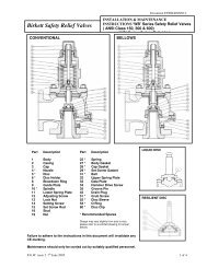


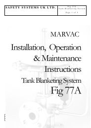
![ES139[IOM Fig 785 Marvac Emergency Relief Vent]](https://img.yumpu.com/43585698/1/190x245/es139iom-fig-785-marvac-emergency-relief-vent.jpg?quality=85)