re29178 - Bosch Rexroth
re29178 - Bosch Rexroth
re29178 - Bosch Rexroth

You also want an ePaper? Increase the reach of your titles
YUMPU automatically turns print PDFs into web optimized ePapers that Google loves.
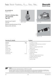
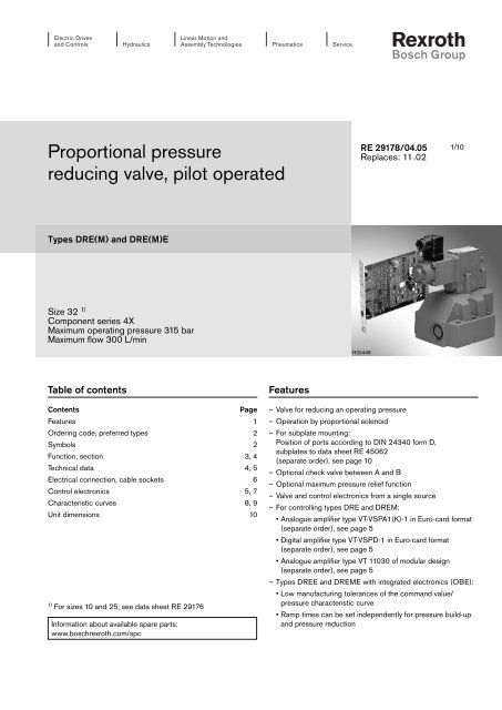
Proportional pressure<br />
reducing valve, pilot operated<br />
Types DRE(M) and DRE(M)E<br />
Size 32 1)<br />
Component series 4X<br />
Maximum operating pressure 315 bar<br />
Maximum flow 300 L/min<br />
Table of contents<br />
Contents Page<br />
Features 1<br />
Ordering code, preferred types 2<br />
Symbols 2<br />
Function, section 3, 4<br />
Technical data 4, 5<br />
Electrical connection, cable sockets 6<br />
Control electronics 5, 7<br />
Characteristic curves 8, 9<br />
Unit dimensions 10<br />
1) For sizes 10 and 25, see data sheet RE 29176<br />
Information about available spare parts:<br />
www.boschrexroth.com/spc<br />
Features<br />
RE 29178/04.05<br />
Replaces: 11.02<br />
H20448<br />
– Valve for reducing an operating pressure<br />
– Operation by proportional solenoid<br />
– For subplate mounting:<br />
Position of ports according to DIN 24340 form D,<br />
subplates to data sheet RE 45062<br />
(separate order), see page 10<br />
– Optional check valve between A and B<br />
– Optional maximum pressure relief function<br />
– Valve and control electronics from a single source<br />
– For controlling types DRE and DREM:<br />
1/10<br />
• Analogue amplifier type VT-VSPA1(K)-1 in Euro-card format<br />
(separate order), see page 5<br />
• Digital amplifier type VT-VSPD-1 in Euro-card format<br />
(separate order), see page 5<br />
• Analogue amplifier type VT 11030 of modular design<br />
(separate order), see page 5<br />
– Types DREE and DREME with integrated electronics (OBE):<br />
• Low manufacturing tolerances of the command value/<br />
pressure characteristic curve<br />
• Ramp times can be set independently for pressure build-up<br />
and pressure reduction
2/10 <strong>Bosch</strong> <strong>Rexroth</strong> AG Hydraulics DRE(M); DRE(M)E RE 29178/04.05<br />
Ordering code<br />
Without maximum pressure<br />
relief function = No code<br />
With maximum pressure<br />
relief function = M<br />
For external control electronics = No code<br />
With integrated electronics (OBE) = E<br />
Size 32 = 30<br />
Component series 40 to 49 = 4X<br />
(40 to 49: unchanged installation and connection dimensions)<br />
Pressure stage<br />
50 bar = 50<br />
100 bar = 100<br />
200 bar = 200<br />
315 bar = 315<br />
Pilot oil drain always external,<br />
separate, and at zero pressure to tank<br />
= Y<br />
With check valve between A and B = No code<br />
Without check valve = M<br />
Preferred types<br />
Type Material no.<br />
DREE 30-4X/50YMG24K31M R900954516<br />
DREE 30 -4X/100YMG24K31M R900954513<br />
DREE 30-4X/200YMG24K31M R900954514<br />
DREE 30-4X/315YMG24K31M R900954515<br />
Symbols<br />
A Y<br />
B<br />
A Y<br />
B<br />
DRE 30 4X Y G24 *<br />
A Y<br />
B<br />
A Y<br />
B<br />
A Y<br />
B<br />
A Y<br />
B<br />
Further details in<br />
clear text<br />
Seal material<br />
M = NBR seals,<br />
suitable for mineral oil (HL, HLP)<br />
to DIN 51524<br />
V = FKM seals<br />
suitable for phosphate ester<br />
(HFD-R)<br />
Electrical connection<br />
for DRE; DREM:<br />
K4 = Without cable socket, with component<br />
plug to DIN EN 175301-803<br />
Cable socket – separate order<br />
see page 6<br />
For DREE; DREME<br />
K31 = Without cable socket, with<br />
component plug to DIN EN 175201-804<br />
Cable socket – separate order<br />
see page 6<br />
Supply voltage of<br />
control electronics<br />
G24 = 24 V DC<br />
DRE 30-4X/...YM… DREM 30-4X/...YM… DRE 30-4X/...Y… DREM 30-4X/...Y…<br />
A Y<br />
DREE 30-4X/...YM… DREME 30-4X/...YM… DREE 30-4X/...Y… DREME 30-4X/...Y…<br />
B<br />
A Y<br />
B
RE 29178/04.05 DRE(M); DRE(M)E Hydraulics <strong>Bosch</strong> <strong>Rexroth</strong> AG 3/10<br />
Function, section<br />
Valves of types DRE and DREM are pilot operated pressure<br />
reducing valves. They are used for reducing an operating pressure.<br />
These valves basically consist of a pilot control valve (1) with<br />
proportional solenoid (2), a main valve (3) with main spool insert<br />
(4) and optionally a check valve (5).<br />
Type DRE...<br />
The pressure in channel A is adjusted by a proportional solenoid<br />
(2) in relation to a current.<br />
At the rest position – no pressure in channel B – the spring<br />
(11) holds the main spool (4) in the initial position. The connection<br />
from channel B to A is open.<br />
The pressure in channel A acts on the bottom side of the main<br />
spool in the direction of closing, and the pressure of the pilot<br />
control valve on the spring side of the main spool in the direction<br />
of opening from channel B to A.<br />
The pilot oil is taken from channel B and flows through the bore<br />
(6) to the constant-flow control valve (9) that keeps the pilot<br />
oil flow constant independently of the pressure drop between<br />
channel A and B. The pilot oil flows from the constant-flow control<br />
valve (9) through bores (7) via the valve seat (10), passes<br />
the valve poppet (8) and is directed into the Y channel to the<br />
tank.<br />
The pressure desired in channel A is pre-selected on the associated<br />
amplifier. The proportional solenoid pushes the valve<br />
9<br />
6<br />
11<br />
12<br />
7 1 10 8 2<br />
X X<br />
13<br />
A B Y<br />
Type DRE. 30-4X/.Y.G24K4… (with check valve)<br />
3<br />
4<br />
5<br />
poppet (8) against the valve seat (10) and limits the pressure in<br />
the spring chamber (12) to the set value. At the control position<br />
of the main spool (4), the hydraulic fluid flows from channel B<br />
to A and generates pressure in channel A (setting of the pilot<br />
control valve plus spring (11)).<br />
When the set pressure is reached in A, a balance of forces is<br />
achieved on the main spool.<br />
When the actuator connected to port A is not moving (e.g.<br />
cylinder piston at end position), and a lower pressure is set in<br />
channel A via the proportional solenoid (2), the main spool (4)<br />
closes the connection from B to A and at the same time opens<br />
the connection from channel A to the spring chamber (12) of<br />
the main spool (4). At this position, the compressed volume in<br />
channel A can expand via the pilot control valve (1) and port Y.<br />
A check valve (5) can optionally be installed to allow a free return<br />
flow from channel A to B.<br />
The reduced pressure in channel A can be checked by means<br />
of a pressure gauge port (13).<br />
Type DREM...<br />
For the hydraulic protection against impermissibly high electrical<br />
control currents on the proportional solenoid, which inevitably<br />
result in high pressures in port A, a spring-loaded pressure<br />
relief valve can optionally be installed as maximum pressure relief<br />
feature (14).<br />
14<br />
X-X<br />
A B<br />
5
4/10 <strong>Bosch</strong> <strong>Rexroth</strong> AG Hydraulics DRE(M); DRE(M)E RE 29178/04.05<br />
Function, section<br />
Types DREE and DREME – with integrated electronics (OBE)<br />
In terms of function and design, these valves correspond to<br />
types DRE and DREM, except for the integrated electronics.<br />
The electronics accommodated in a housing (15) receives the<br />
supply voltage and command value voltage via the cable socket<br />
(16).<br />
The command value/pressure characteristic curve (zero point<br />
on valve seat (10) and gradient on Imax po ten tio me ter (R30) in<br />
the electronics) is adjusted in the factory with narrow manufacturing<br />
tolerances.<br />
The ramp time for pressure build-up and pressure reduction<br />
can be adjusted independently of each other using two potentiometers.<br />
For further information on the integrated electronics, see page 7.<br />
Technical data (for applications outside these parameters, please consult us!)<br />
General data<br />
Weight – DRE and DREM kg 8.6<br />
– DREE and DREME kg 8.7<br />
Installation orientation Optional<br />
Storage temperature range °C – 20 to + 80<br />
Ambient – DRE and DREM °C – 20 to + 70<br />
temperature range – DREE and DREME °C – 20 to + 50<br />
Hydraulic (measured with HLP 46; ϑoil = 40 °C ± 5 °C )<br />
Max. operating pressure – Ports A and B bar 315<br />
– Port Y Separately and at zero pressure to tank<br />
Max. set pressure – Pressure stage 50 bar bar 50<br />
in channel A – Pressure stage 100 bar bar 100<br />
– Pressure stage 200 bar bar 200<br />
– Pressure stage 315 bar bar 315<br />
Min. set pressure in channel A with zero command value bar See p min -q v characteristic curve on page 9<br />
Maximum pressure relief function (infinitely adjustable): Adjustment range: Factory setting:<br />
– Pressure stage 50 bar bar 30 to 70 to 70 bar<br />
– Pressure stage 100 bar bar 50 to 130 to 130 bar<br />
– Pressure stage 200 bar bar 90 to 230 to 230 bar<br />
– Pressure stage 315 bar bar 150 to 350 to 350 bar<br />
Max. flow of main valve L/min 300<br />
Pilot oil flow L/min See characteristic curve on page 9<br />
16<br />
15
RE 29178/04.05 DRE(M); DRE(M)E Hydraulics <strong>Bosch</strong> <strong>Rexroth</strong> AG 5/10<br />
Technical data (for applications outside these parameters, please consult us!)<br />
Hydraulic (measured with HLP 46; ϑ oil = 40 °C ± 5 °C )<br />
Hydraulic fluid Mineral oil (HL, HLP) to DIN 51524,<br />
phosphate ester (HFD-R)<br />
Hydraulic fluid temperature range °C – 20 to + 70<br />
Viscosity range mm 2 /s 15 to 380<br />
Max. permissible degree of contamination of the hydraulic<br />
fluid - cleanliness class to ISO 4406 (c)<br />
Class 20/18/15 1)<br />
Hysteresis % ± 2.5 of max. set pressure<br />
Repeatability % < ± 2 of max. set pressure<br />
Linearity % ± 3.5 of max. set pressure<br />
Manufacturing tolerances – DRE and DREM % ± 2 of max. set pressure<br />
of comand value/pressure – DREE and DREME % ± 1.5 of max. set pressure<br />
curve referred to hysteresis curve, increasing pressure<br />
Switching time<br />
Electrical<br />
ms 100 to 300 (depending on system)<br />
Supply voltage V 24 DC<br />
Min. solenoid current – DRE and DREM mA 100<br />
– DREE and DREME mA 100<br />
Max. solenoid current – DRE and DREM mA 800 (corresponds to 100 % command value)<br />
– DREE and DREME mA 1440 to 1760<br />
Solenoid coil resistance – Cold value at 20 °C Ω 19.5 with DRE / DREM; 5.4 Ω with DREE / DREME<br />
– Max. hot value Ω 28.8 with DRE / DREM; 7.8 Ω with DREE / DREME<br />
Duty cycle % 100<br />
Electrical connection – DRE and DREM With component plug to DIN EN 175301-803<br />
Cable socket to DIN EN 175301-803 2)<br />
– DREE and DREME With component plug to DIN EN 175201-804<br />
Cable socket to DIN EN 175201-804 2)<br />
Type of protection of valve to EN 60529 IP 65 with cable socket mounted and locked 3)<br />
Control electronics<br />
– For DREE and DREME<br />
– For DRE and DREM<br />
Integrated in the valve, see page 7<br />
• Amplifier in Euro-card format analogue VT-VSPA1(K)-1 to data sheet RE 30111<br />
(separate order) digital VT-VSPD-1 to data sheet RE 30123<br />
• Amplifier of modular design (separate order) analogue VT 11030 to data sheet RE 29741<br />
1) The cleanliness classes specified for components must be<br />
adhered to in hydraulic systems. Effective filtration prevents<br />
malfunction and, at the same time, prolongs the service life<br />
of components.<br />
For the selection of filters, see data sheets RE 50070,<br />
RE 50076, RE 50081, RE 50086 and RE 50088.<br />
2) Separate order, see page 6<br />
3) Special types of protection on enquiry<br />
Note: For details regarding environment simulation<br />
testing in the fields of EMC (electromagnetic<br />
compatibility), climate and mechanical stress,<br />
see RE 29176-U (declaration on environmental<br />
compatibility).
6/10 <strong>Bosch</strong> <strong>Rexroth</strong> AG Hydraulics DRE(M); DRE(M)E RE 29178/04.05<br />
Electrical connection, cable sockets (nominal dimensions in mm)<br />
Connection to component plug Connection to cable socket<br />
18<br />
1<br />
Ø27<br />
91<br />
10A<br />
250V<br />
PE<br />
1 2<br />
For types DRE, DREM – for external control electronics<br />
Cable socket to DIN EN 175301-803<br />
Separate order under material no. R901017011<br />
27,5<br />
2<br />
1<br />
GDM<br />
43<br />
1 Fixing screw M3,<br />
titghtening torque M T = 0.5 Nm<br />
~10<br />
Ø6,5…Ø11<br />
34,2<br />
5,5<br />
For types DREE, DREME – with integrated electronics (OBE)<br />
Cable socket to DIN EN 175201-804<br />
Separate order under material no. R900021267<br />
(made of plastic)<br />
For the pin assignment, see block circuit diagram on page 7.<br />
B<br />
C<br />
D<br />
A F<br />
E<br />
PE<br />
1 2<br />
to amplifier
RE 29178/04.05 DRE(M); DRE(M)E Hydraulics <strong>Bosch</strong> <strong>Rexroth</strong> AG 7/10<br />
Integrated electronics (OBE) for types DREE, DREME<br />
Function<br />
The integrated electronics is controlled via both differential amplifier<br />
connections D and E.<br />
The ramp generator generates from a command value stepchange<br />
(0 to 10 V or 10 to 0 V) a delayed rise or drop of the<br />
solenoid current. The rise time can be adjusted by means of<br />
potentiometer R14, the drop time of the solenoid current using<br />
potentiometer R13.<br />
The maximum ramp time of 5 s is only possible over the full<br />
command value range. With minor command value changes,<br />
the ramp time shortens.<br />
The command value/solenoid current characteristic curve is adjusted<br />
to the valve by means of the characteristic curve generator<br />
so that non-linearities in the hydraulic system are compensated<br />
for and a linear command value/pressure characteristic<br />
curve is obtained.<br />
Block circuit diagram / pin assignment of integrated electronics<br />
Command value 0 to 10 V<br />
0V reference potential<br />
Supply voltage:<br />
U eff : 22 to 33 V<br />
Supply voltage<br />
0 V<br />
D<br />
+<br />
E<br />
–<br />
F<br />
C<br />
A<br />
+<br />
B<br />
n.c.<br />
n.c.<br />
Dif fe rential<br />
amplifier<br />
U<br />
=<br />
U<br />
=<br />
Ramp<br />
generator<br />
R 14 R 13<br />
Ram p<br />
“up“<br />
Power supply unit<br />
+U<br />
+7,5 V<br />
-7,5 V<br />
Power supply unit with rectifier<br />
Single-phase rectification or three-phase bridge :<br />
Ueff = 22 to 33 V<br />
Residual ripple content on the power supply unit: < 5 %<br />
Output current: Ieff = max. 1.4 A<br />
Supply cable: – Recommendation: 5-wire 0.75 or 1 mm2 with protective conductor and shield<br />
– Outer diameter 6.5 to 11 mm<br />
– Shield to 0 V supply voltage<br />
Ram p<br />
“down“<br />
– Max. permissible length 100 m<br />
The minimum supply voltage of the power supply unit depends<br />
on the length of the supply cable (see diagram).<br />
In the case of lengths > 50 m, a capacitor of 2200 µF must be<br />
provided near the valve in the supply cable.<br />
The current regulator regulates the solenoid current independently<br />
of the solenoid coil resistance.<br />
Potentiometer R30 can be used for changing the gradient of<br />
the command value/current characteristic curve and hence the<br />
gradient of the command value/pressure characteristic curve of<br />
the proportional pressure control valve.<br />
Potentiometer R43 is used for adjusting the biasing current. Its<br />
setting should not be changed. If required, the zero point of the<br />
command value/pressure characteristic curve can be adjusted<br />
on the valve seat.<br />
The power stage of the electronics for controlling the proportional<br />
solenoid is a chopper amplifier. It is pulse-width-modulated<br />
and has a clock frequency of 300 Hz.<br />
The solenoid current can be measured at the two measuring<br />
sockets MP1 and MP2. A voltage drop of 0.352 V at the measuring<br />
shunt corresponds to a solenoid current of 1.6 A.<br />
Char. curve<br />
generator<br />
Internal reference point<br />
Min. supply voltage in V →<br />
R 30 I R 43<br />
30<br />
28<br />
26<br />
24<br />
22<br />
Current<br />
regulator<br />
I max<br />
300 Hz<br />
=<br />
I min<br />
Oscillator<br />
+U<br />
Chopper<br />
amplifier<br />
Measuring shunt<br />
R = 0.22 Ω<br />
0 V<br />
20 40 60 80 100<br />
Length of supply cable in m →<br />
Solenoid<br />
MP1<br />
1,6 A =<br />
0,352 V<br />
MP2<br />
0,75 mm 2<br />
1 mm 2
8/10 <strong>Bosch</strong> <strong>Rexroth</strong> AG Hydraulics DRE(M); DRE(M)E RE 29178/04.05<br />
Characteristic curves (measured with HLP46, ϑ oil = 40 °C ± 5 °C)<br />
Pressure in channel A in dependence on command value (measured at flow of 0 L/min from B to A and with associated control<br />
electronics)<br />
Pressure in channel A in bar →<br />
Pressure in channel A in bar →<br />
Pressure stage 50 bar Pressure stage 100 bar<br />
50<br />
100<br />
90<br />
40<br />
30<br />
20<br />
Dead range<br />
10<br />
0<br />
160<br />
140<br />
120<br />
100<br />
80<br />
60<br />
40<br />
20<br />
0<br />
25 50 75<br />
Command value in % →<br />
25 50 75<br />
Command value in % →<br />
100<br />
100<br />
80<br />
70<br />
60<br />
50<br />
40<br />
30<br />
20<br />
10<br />
0<br />
25 50 75<br />
Command value in % →<br />
Pressure stage 200 bar Pressure stage 315 bar<br />
200<br />
315<br />
300<br />
180<br />
300<br />
250<br />
200<br />
150<br />
100<br />
50<br />
Dead range<br />
0 0,1 1 5 10 50 100 200 300<br />
Flow in L/min →<br />
Druck im Kanal A in bar →<br />
250<br />
200<br />
150<br />
100<br />
Dead range<br />
50<br />
0<br />
100<br />
80<br />
60<br />
40<br />
20<br />
0<br />
Dead range<br />
25 50 75<br />
Command value in % →<br />
Note: In order that the lowest settable pressure is achieved, the biasing current must not exceed max. 100 mA.<br />
Pressure in channel A in dependence on flow q v<br />
Pressure in channel A in bar →<br />
Pressure in channel A in bar →<br />
100<br />
100<br />
Pressure in channel A in dependence on pressure in channel B<br />
Pressure in channel A in bar →<br />
50 100 150 200 250 300<br />
Pressure in channel B in bar →
RE 29178/04.05 DRE(M); DRE(M)E Hydraulics <strong>Bosch</strong> <strong>Rexroth</strong> AG 9/10<br />
Charcteristic curves (measured with HLP46, ϑ oil = 40 °C ± 5 °C)<br />
Min. set pressure in bar →<br />
12<br />
10<br />
8<br />
6<br />
4<br />
2<br />
0<br />
10<br />
8<br />
6<br />
4<br />
2<br />
0<br />
p min -q v characteristic curve<br />
50 100 150 200 250 300<br />
Flow in L/min →<br />
Pressure differential from A to B across check valve Pilot oil flow<br />
Pressure differential in bar →<br />
50 100 150 200 250 300<br />
Flow in L/min →<br />
Pilot oil flow in L/min →<br />
3,0<br />
2,0<br />
1,4<br />
1,0<br />
0<br />
50 100 150 200 250 300<br />
Flow in L/min →
10/10 <strong>Bosch</strong> <strong>Rexroth</strong> AG Hydraulics DRE(M); DRE(M)E RE 29178/04.05<br />
Unit dimensions (nominal dimensions in mm)<br />
170<br />
154,5<br />
16<br />
11 9<br />
120<br />
96,8<br />
3 1 14 12<br />
3<br />
16,7<br />
Y<br />
24,6<br />
42,1<br />
A B<br />
113<br />
Ø 6<br />
7; 10<br />
A B<br />
Y<br />
6<br />
Ø 18<br />
Ø 11<br />
3,8<br />
46<br />
5<br />
206 15<br />
Pg1<br />
45<br />
92,8<br />
8 59,5<br />
6<br />
<strong>Bosch</strong> <strong>Rexroth</strong> AG<br />
Hydraulics<br />
Zum Eisengießer 1<br />
97816 Lohr am Main, Germany<br />
Phone +49 (0) 93 52 / 18-0<br />
Fax +49 (0) 93 52 / 18-23 58<br />
documentation@boschrexroth.de<br />
www.boschrexroth.de<br />
Y<br />
62,7<br />
67,5<br />
28 84,2<br />
140<br />
176,5<br />
244,5 (with integrated electronics)<br />
2<br />
13<br />
4<br />
5<br />
1 This port (G1/4) is plugged when the valve<br />
leaves the factory. After the plug was removed,<br />
the port can be used for separate<br />
external pilot oil draining to tank at zero<br />
pressure.<br />
2 Space required to remove cable socket<br />
3 Nameplate<br />
4 Maximum pressure relief valve type<br />
DREM…<br />
When using these valves, observe the technical<br />
data on page 4!<br />
5 Check valve, optional<br />
6 Locating pin<br />
7 Pilot oil drain always external and separately<br />
at zero pressure to tank<br />
8 Blind counterbore<br />
9 Identical seal rings for ports A and B<br />
10 Identical seal rings for port Y and blind<br />
counterbore (item 8)<br />
11 Pressure gauge port G 1/4; 12 deep<br />
12 Cable socket for type DRE(M)<br />
(separate order, see page 6)<br />
13 Cable socket for type DRE(M)E<br />
(separate order, see page 6)<br />
14 Integrated electronics (OBE), type<br />
DRE(M)E with component plug “K31“<br />
Subplates according to data sheet<br />
RE 45062 and valve fixing screws must be ordered<br />
separately.<br />
Subplates: G 414/01 (G 1 1/4)<br />
G 415/01 (G 1 1/2)<br />
Valve fixing screws:<br />
6 off M10 x 70 DIN 912-10.9,<br />
Tightening torque MT = 75 Nm<br />
Tolerances according to:<br />
– General tolerances ISO 2768-mK<br />
– Tolerancing principle ISO 8015<br />
0,01/100mm<br />
Rzmax 4<br />
Required surface finish<br />
of the mating part<br />
© This document, as well as the data, specifi cations and other<br />
information set forth in it, are the exclusive property of <strong>Bosch</strong> <strong>Rexroth</strong><br />
AG. Without their consent it may not be reproduced or given to third<br />
parties.<br />
The data specifi ed above only serve to describe the product. No<br />
statements concerning a certain condition or suitability for a certain<br />
application can be derived from our information. The given information<br />
does not release the user from the obligation of own judgement and<br />
verifi cation. It must be remembered that our products are subject to a<br />
natural process of wear and aging.
RE 29178/04.05 DRE(M); DRE(M)E Hydraulics <strong>Bosch</strong> <strong>Rexroth</strong> AG 11/10<br />
Notes<br />
<strong>Bosch</strong> <strong>Rexroth</strong> AG<br />
Hydraulics<br />
Zum Eisengießer 1<br />
97816 Lohr am Main, Germany<br />
Phone +49 (0) 93 52 / 18-0<br />
Fax +49 (0) 93 52 / 18-23 58<br />
documentation@boschrexroth.de<br />
www.boschrexroth.de<br />
© This document, as well as the data, specifi cations and other<br />
information set forth in it, are the exclusive property of <strong>Bosch</strong> <strong>Rexroth</strong><br />
AG. Without their consent it may not be reproduced or given to third<br />
parties.<br />
The data specifi ed above only serve to describe the product. No<br />
statements concerning a certain condition or suitability for a certain<br />
application can be derived from our information. The given information<br />
does not release the user from the obligation of own judgement and<br />
verifi cation. It must be remembered that our products are subject to a<br />
natural process of wear and aging.
12/10 <strong>Bosch</strong> <strong>Rexroth</strong> AG Hydraulics DRE(M); DRE(M)E RE 29178/04.05<br />
Notes<br />
<strong>Bosch</strong> <strong>Rexroth</strong> AG<br />
Hydraulics<br />
Zum Eisengießer 1<br />
97816 Lohr am Main, Germany<br />
Phone +49 (0) 93 52 / 18-0<br />
Fax +49 (0) 93 52 / 18-23 58<br />
documentation@boschrexroth.de<br />
www.boschrexroth.de<br />
© This document, as well as the data, specifi cations and other<br />
information set forth in it, are the exclusive property of <strong>Bosch</strong> <strong>Rexroth</strong><br />
AG. Without their consent it may not be reproduced or given to third<br />
parties.<br />
The data specifi ed above only serve to describe the product. No<br />
statements concerning a certain condition or suitability for a certain<br />
application can be derived from our information. The given information<br />
does not release the user from the obligation of own judgement and<br />
verifi cation. It must be remembered that our products are subject to a<br />
natural process of wear and aging.