Axial Piston Pump
Axial Piston Pump
Axial Piston Pump

Create successful ePaper yourself
Turn your PDF publications into a flip-book with our unique Google optimized e-Paper software.
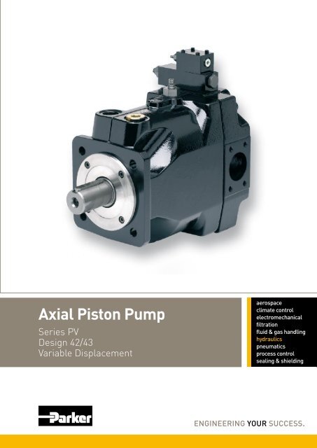
<strong>Axial</strong> <strong>Piston</strong> <strong>Pump</strong><br />
Series PV<br />
Design 42/43<br />
Variable Displacement
Catalogue HY30-3243/UK<br />
Contents<br />
<strong>Axial</strong> <strong>Piston</strong> <strong>Pump</strong><br />
Series PV<br />
Contents Page<br />
Introduction .....................................................................................................3<br />
Ordering Code Preferred Program .................................................................4<br />
Noise Levels ...................................................................................................8<br />
Efficiency and Case Drain Flows ....................................................................9<br />
Dimensions ...................................................................................................11<br />
Mounting kits ................................................................................................17<br />
<strong>Pump</strong> combinations<br />
Thru Drive, Shaft Load Limitations .....................................................18<br />
Compensators<br />
Compensators Dimensions ................................................................19<br />
Pressure Compensators ....................................................................23<br />
Load-Sensing Compensators.............................................................24<br />
Power Compensators .........................................................................25<br />
Power Compensators, Diagrams........................................................26<br />
Electronic Module PQDXXA (digital) ..................................................28<br />
General Installation Information .........................................................29<br />
Accessories Compensator .................................................................30<br />
2<br />
Parker Hannifin<br />
<strong>Pump</strong> and Motor Division<br />
Chemnitz, Germany
Catalogue HY30-3243/UK<br />
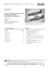
Introduction<br />
Technical Features<br />
• Low noise level<br />
• Fast response<br />
• Service-friendly<br />
• High self-priming speed<br />
• Compact design<br />
• Thru drive for 100% nominal torque<br />
Technical Data<br />
<strong>Axial</strong> <strong>Piston</strong> <strong>Pump</strong><br />
Series PV<br />
Size PV063 PV080 PV092 PV140 PV180 PV270<br />
Max. Displacement [cm3/rev.] 63 80 92 140 180 270<br />
Output flow at 1500 min-1 [l/min] 94.5 120 138 210 270 405<br />
Nominal pressure pN [bar] 350 350 350 350 350 350<br />
Max. pressure pmax 1) [bar] 420 420 420 420 420 420<br />
Max. Case drain pressure [bar] 0.5 0.5 0.5 0.5 0.5 0.5<br />
Min. Inlet pressure, abs. [bar] 0.8 0.8 0.8 0.8 0.8 0.8<br />
Max. Inlet pressure [bar] 16 16 16 16 16 16<br />
Input power at 1500 min-1 and 350 bar [kW] 61.5 78 89.5 136 175 263<br />
Max speed 2) [min -1 ] 2800 2500 2300 2400 2200 1800<br />
Moment of inertia [kgm 2 ] 0.018 0.018 0.018 0.030 0.030 0.098<br />
Weight [kg] 60 60 60 90 90 172<br />
1) Maximum 20% of the working cycle.<br />
2) The maximum speed ratings are shown for an inlet pressure of 1 bar (absolute) and for a fluid viscosity of<br />
ν= 30 mm 2 /s<br />
General Information<br />
Premium quality hydraulic mineral fluid are recommended,<br />
like HLP oils to DIN 51522, part 2, Brugger- value<br />
has to be 30 N/mm² minimum for general application<br />
and 50 N/mm² for heavily loaded hydraulic equipment<br />
and fast cycling machines and/or high dynamic loads,<br />
measured in accordance with DIN 51 347-2, see also<br />
Document HY30-3248/UK Parker Hydraulic- Fluids.<br />
Viscosity<br />
The normal operating viscosity should range between<br />
16 and 100 mm 2 /s (cSt). Max. start-up viscosity is<br />
800 mm 2 /s (cSt).<br />
Seals<br />
NBR seals are used for operation with hydraulic fluids<br />
based on mineral oil. For synthetic fluids, such as<br />
phosphoric acid esters, Flourocarbon seal are required.<br />
3<br />
With thru drive for single and multiple pumps<br />
Swash plate type for open circuit<br />
Filtration<br />
For maximum pump and system component functionability<br />
and life, the system should be protected from<br />
contamination by effective filtration.<br />
Fluid cleanliness should be in accordance with ISO<br />
classification ISO 4406:1999. The quality of filter elements<br />
should be in accordance with ISO standards.<br />
Minimum requirement for filtration rate x (mm);<br />
General hydraulic systems for satisfactory operation:<br />
Class 20/18/15, according to ISO 4406:1999<br />
Hydraulic systems with maximised component life and<br />
functionability:<br />
Class 18/16/13, according to ISO 4406:1999<br />
Parker Hannifin<br />
<strong>Pump</strong> and Motor Division<br />
Chemnitz, Germany
Catalogue HY30-3243/UK<br />
Ordering Code Preferred Program<br />
<strong>Axial</strong> piston<br />
pump<br />
variable<br />
displacement<br />
high<br />
pressure<br />
version<br />
Code Rotation 1)<br />
R Clockwise<br />
1) When looked on shaft<br />
Size<br />
and<br />
displacement<br />
<strong>Axial</strong> <strong>Piston</strong> <strong>Pump</strong><br />
Series PV<br />
P V R 1 K 1 T 1 N<br />
Code Displacement Size<br />
063 63 cm³/rev 3<br />
080 80 cm³/rev 3<br />
092 92 cm³/rev 3<br />
140 140 cm³/rev 4<br />
180 180 cm³/rev 4<br />
270 270 cm³/rev 5<br />
Rotation<br />
Code Mounting interface Shaft<br />
K metr. ISO 4-hole flange Cylindric, key<br />
L 3019/2 4-hole flange Splined, DIN 5480<br />
Code Port 2) Threads 3)<br />
1 BSPP Metric<br />
4 4) BSPP Metr. M14<br />
<strong>Pump</strong> Compensator<br />
Standard Threads 2nd<br />
Compensator<br />
Design<br />
pump<br />
series:<br />
(not required<br />
for order)<br />
Mounting<br />
code Thru drive<br />
2) Drain, gauge and flushing ports<br />
3) All mounting and connecting threads<br />
4) For PV063-PV180 only: pressure port 1 1/4” with 4 x M14 instead of 4 x M12<br />
4<br />
Seals<br />
Mounting kits for flexible mounting of multiple pumps, see page 17.<br />
see opposite page<br />
Code Seals<br />
N NBR<br />
Code 2nd pump option 5)<br />
1 Single pump, no 2nd pump<br />
and coupling<br />
Code Thru drive option<br />
no adaptor for 2nd pump<br />
T Single pump<br />
prepared for thru drive<br />
Parker Hannifin<br />
<strong>Pump</strong> and Motor Division<br />
Chemnitz, Germany
Catalogue HY30-3243/UK<br />
Ordering Code Preferred Program<br />
Standard Pressure Compensator<br />
Code Compensator options<br />
0 0 1 Without compensator<br />
F D S 10 - 140 bar, spindle + lock nut<br />
F H S 40 - 210 bar, spindle + lock nut<br />
F W S 70 - 350 bar, spindle + lock nut<br />
Remote Compensator options<br />
F R Remote pressure compensator<br />
F F Load-Sensing compensator<br />
Variations for Remote Compensator<br />
C External pressure pilot 8)<br />
1 NG6/D03 interface top side<br />
P Pilot valve PVAC1P* mounted<br />
Power compensator<br />
Code Displacement Compensator option<br />
063 140 180 270 Nom. power [kW] Nom. torque-<br />
092 at 1500 min -1 [Nm]<br />
G 11 71<br />
H 15 97<br />
K 18.5 120<br />
M 22 142<br />
S 30 195<br />
T 37 240<br />
U 45 290<br />
W 55 355<br />
Y 75 485<br />
Z 90 585<br />
2 110 715<br />
3 132 850<br />
Function<br />
L Power compensator<br />
C Power compensator<br />
and load-sensing<br />
Variation<br />
A NG6 interface top side<br />
B No pressure compensation<br />
C Adjustable<br />
pressure compensation<br />
Code Compensator style<br />
electro hydraulic control<br />
F P V closed loop displacement control only, no<br />
pressure compensation<br />
U P closed loop proportional displacement<br />
control with pressure compensation<br />
compensator version<br />
R balanced pressure control, NG6 interface<br />
K version UPR, with proportional pilot valve<br />
type PVACRE..35 mounted<br />
M version UPK, with pressure sensor for<br />
closed loop pressure and power control<br />
<strong>Axial</strong> <strong>Piston</strong> <strong>Pump</strong><br />
Series PV<br />
5<br />
Note:<br />
Compensator differential ∆p is factory pre-set to:<br />
remote compensators, power control 15 ± 1 bar<br />
load sensing comp. (not power control) 10 ± 1 bar<br />
Parker Hannifin<br />
<strong>Pump</strong> and Motor Division<br />
Chemnitz, Germany
Catalogue HY30-3243/UK<br />
Ordering Code Options on Request<br />
P V<br />
axial piston<br />
pump<br />
variable<br />
displacement<br />
high<br />
pressure<br />
version<br />
Code Displacement Size<br />
063 63 cm³/rev 3<br />
080 80 cm³/rev 3<br />
092 92 cm³/rev 3<br />
140 140 cm³/rev 4<br />
180 180 cm³/rev 4<br />
270 270 cm³/rev 5<br />
Code Rotation 1)<br />
R Clockwise<br />
L Counter clockwise<br />
1) When looked on shaft<br />
Code Variation<br />
1 Standard<br />
9 special<br />
adjustment 2)<br />
2) requires Kxxxx number<br />
size<br />
and<br />
displacement<br />
Code Mounting interface Shaft<br />
D<br />
E<br />
F<br />
4-hole flange<br />
4-hole flange<br />
Cylindric, key<br />
Splined, SAE<br />
3) G<br />
4-hole flange Cylindric, key<br />
3) SAE<br />
ISO<br />
3019/1<br />
4-hole flange Splined, SAE<br />
K metr. ISO 4-hole flange Cylindric, key<br />
L 3019/2 4-hole flange Splined, DIN 5480<br />
3) Codes F and G only for PV140/180<br />
Code Port 4) Threads 5)<br />
1 BSPP metric<br />
3 UNF UNC<br />
4 6) BSPP metr. M14<br />
7 ISO 6149 UNC<br />
8 ISO 6149 metrisch<br />
4) Drain, gauge and flushing ports<br />
5) All mounting and connecting threads<br />
6) For PV063, PV080-PV180 only: pressure port 1 1/4”<br />
with 4 x M14 instead of 4 x M12<br />
<strong>Axial</strong> <strong>Piston</strong> <strong>Pump</strong><br />
Series PV<br />
R 1 1 N 1 K T<br />
compensator<br />
rotation<br />
Mounting kits for flexible mounting of<br />
multiple pumps, see page 17.<br />
mounting<br />
interface<br />
variation threads<br />
code<br />
thru drive<br />
code<br />
6<br />
coupling<br />
code<br />
seals<br />
Code Coupling for thru drive<br />
1 Single pump, no coupling<br />
2 PV140 or PV180 mounted<br />
3 PV pump mounted<br />
4 Gear pump mounted<br />
Code Thru drive option<br />
No adaptor for 2nd pump<br />
T Single pump prepared<br />
for thru drive<br />
Code Seals<br />
N NBR<br />
V FPM<br />
W NBR with PTFE shaft seal<br />
P FPM with PTFE shaft seal<br />
with adaptor for 2nd pump as single part 10)<br />
A SAE A, Ø 82.55 mm MK-PVBGxAMN<br />
B SAE B, Ø 101.6 mm MK-PVBGxBMN<br />
C7) SAE C, Ø 127 mm MK-PVBGxCMN<br />
D7) SAE D, Ø 152,4 mm MK-PVBGxDMN<br />
E8) SAE E, Ø 165,1 mm MK-PVBGxEMN<br />
G9) metric, Ø 63 mm MK-PVBGxGMN<br />
H metric, Ø 80 mm MK-PVBGxHMN<br />
J metric, Ø 100 mm MK-PVBGxJMN<br />
K7) metric, Ø 125 mm MK-PVBGxKMN<br />
L7) metric, Ø 160 mm MK-PVBGxLMN<br />
M8) metric, Ø 200 mm MK-PVBGxMMN<br />
See dimensions for details<br />
7) only for PV063 and larger<br />
8) only for PV270<br />
9) only for PV063 - PV092<br />
10) x= frame size, see page 17.<br />
see next page<br />
Option 2, 3 and 4 not available for single pump. Second pump<br />
must be specified with full model code.<br />
Parker Hannifin<br />
<strong>Pump</strong> and Motor Division<br />
Chemnitz, Germany
Catalogue HY30-3243/UK<br />
Ordering Code Options on Request<br />
Code<br />
Standard Pressure Compensator<br />
Compensator options<br />
0 0 1 No compensator<br />
1 0 0 With cover plate, no control function<br />
F D S 10 - 140 bar, Spindle + lock nut<br />
F H S 40 - 210 bar, Spindle + lock nut<br />
F W S 70 - 350 bar, Spindle + lock nut<br />
Remote compensator options<br />
F R Remote pressure compensator<br />
F S Variation R, for quick unload valve<br />
F F Load-Sensing compensator<br />
F T Two valve load-sensing compensator<br />
Compensator variation<br />
C External pressure pilot 14)<br />
1 NG6 interface top side for pilot valves<br />
2 Like 1 but with ext. pilot port16) P Pilot valve PVAC1P* mounted<br />
K Prop.-pilot valve type PVACRE..35 mounted<br />
L Pilot valve with DIN lock mounted<br />
Z Accessory mounted 15)<br />
Horse power compensator<br />
Code Displacement Compensator option<br />
063 140 180 270 Nominal HP. [kW] Nom. torque<br />
100 at 1500 rpm [Nm]<br />
G 11 71<br />
H 15 97<br />
K 18,5 120<br />
M 22 142<br />
S 30 195<br />
T 37 240<br />
U 45 290<br />
W 55 355<br />
Y 75 485<br />
Z 90 585<br />
2 110 715<br />
3 132 850<br />
Function<br />
L Horse power compensator<br />
C Horse power compensator<br />
and Load Sensing<br />
Compensator variation<br />
A NG 6 interface top side<br />
B No pressure compensation<br />
C Adjustable pressure compensation<br />
K Prop.-pilot valve<br />
type PVACRE..35 mounted<br />
Z Accessories mounted 15)<br />
<strong>Axial</strong> <strong>Piston</strong> <strong>Pump</strong><br />
Series PV<br />
7<br />
Electrohydraulic compensator<br />
Code Compensator option<br />
Pilot pressure supply<br />
F P V closed loop displacement control only,<br />
no pressure compensation<br />
Function<br />
U P Proportionalhubvolumenregelung<br />
Variation<br />
R balanced pressure control, NG6 interface<br />
K version UPR, with proportional pilot valve<br />
type PVACRE..35 mounted<br />
M version UPK, with pressure sensor for<br />
closed loop pressure and power control<br />
Z Version R, accessories mounted 15)<br />
Note<br />
Compensator differential ∆p is to be adjusted:<br />
remote compensators, power control 15 ± 1 bar<br />
(Codes FR*, FT*, *L*, *C*, UPR, UPD, UPZ, UPG)<br />
load sensing comp. (not power control) 10 ± 1 bar<br />
(Codes FF*)<br />
14) Not for two-valve-compensator<br />
15) Accessories not included, please specify on<br />
order with full model code.<br />
16) Only Codes *FR* and *FT*<br />
Parker Hannifin<br />
<strong>Pump</strong> and Motor Division<br />
Chemnitz, Germany
Catalogue HY30-3243/UK<br />
Noise Levels<br />
PV063 - PV092<br />
Noise level [dB(A)]<br />
PV140<br />
Noise level [dB(A)]<br />
70<br />
60<br />
52<br />
0 100 200 300<br />
Pressure [bar]<br />
80<br />
70<br />
at full flow<br />
at full flow<br />
at deadhead<br />
at deadhead<br />
<strong>Axial</strong> <strong>Piston</strong> <strong>Pump</strong><br />
Series PV<br />
8<br />
PV180<br />
PV270<br />
60<br />
0 100 200 300<br />
60<br />
0 100 200 300<br />
Pressure [bar] Pressure [bar]<br />
Typical sound level for single pumps, measured in unechoic chamber<br />
according to DIN 45 635, part 1 and 26. Microphone distance 1m;<br />
speed: n = 1500 rpm.<br />
Noise level [dB(A)]<br />
Noise level [dB(A)]<br />
80<br />
70<br />
60<br />
0 100 200 300<br />
Pressure [bar]<br />
80<br />
70<br />
at full flow<br />
at full flow<br />
at deadhead<br />
at deadhead<br />
All data measured with mineral oil viscosity 30 mm²/s (cSt) at 50°C.<br />
Parker Hannifin<br />
<strong>Pump</strong> and Motor Division<br />
Chemnitz, Germany
Catalogue HY30-3243/UK<br />
Efficiency and Case Drain Flows<br />
Efficiency, power consumption<br />
PV063<br />
Output flow [l/min]<br />
100<br />
80<br />
60<br />
40<br />
20<br />
0<br />
PV080<br />
Output flow [l/min]<br />
120<br />
96<br />
72<br />
48<br />
24<br />
0<br />
PV092<br />
Output flow [l/min]<br />
150<br />
120<br />
90<br />
60<br />
30<br />
0<br />
Input power [kW]<br />
Input power [kW]<br />
Input power [kW]<br />
70<br />
56<br />
42<br />
28<br />
14<br />
0<br />
0 100 200 300<br />
Pressure [bar]<br />
80<br />
64<br />
48<br />
32<br />
16<br />
0<br />
0 100 200 300<br />
Pressure [bar]<br />
100<br />
80<br />
60<br />
40<br />
20<br />
output flow<br />
vol. efficiency<br />
overall efficiency<br />
input power at full flow<br />
input power at deadhead<br />
output flow, vol. efficiency<br />
output flow<br />
overall efficiency<br />
input power at full flow<br />
input power at deadhead<br />
vol. efficiency<br />
overall efficiency<br />
input power at full flow<br />
input power at deadhead<br />
0<br />
0 100 200 300<br />
Pressure [bar]<br />
100<br />
80<br />
60<br />
40<br />
20<br />
0<br />
100<br />
80<br />
60<br />
40<br />
20<br />
0<br />
100<br />
80<br />
60<br />
40<br />
20<br />
0<br />
Efficiency [%] (overall, volymetric)<br />
Efficiency [%] (overall, volymetric)<br />
Efficiency [%] (overall, volymetric)<br />
<strong>Axial</strong> <strong>Piston</strong> <strong>Pump</strong><br />
Series PV<br />
9<br />
Efficiency and case drain flows PV063, PV080, PV092<br />
The efficiency and power graphs are measured at an<br />
input speed of n = 1500 rpm, a temperature of 50 °C and<br />
a fluid viscosity of 30 mm2 /s.<br />
Case drain flow and compensator control flow leave via<br />
the drain port of the pump. To the values shown are to be<br />
added 1 to 1.2 l/min , if at pilot operated compensators<br />
(codes FR*, FF*, FT*, power compensator and p-Q-control)<br />
the control flow of the pressure pilot valve also goes<br />
through the pump.<br />
Please note: The values shown below are only valid for<br />
static operation. Under dynamic conditions and at rapid<br />
compensation of the pump the volume displaced by the<br />
servo piston also leaves the case drain port. This dynamic<br />
control flow can reach up to 80 l/min! Therefore the case<br />
drain line is to lead to the reservoir at full size and without<br />
restrictions as short and direct as possible.<br />
Case drain flows PV063-092<br />
Drain flow [l/min]<br />
12<br />
8<br />
4<br />
dead head<br />
full flow<br />
0<br />
0 100 200 300<br />
Pressure [bar]<br />
Parker Hannifin<br />
<strong>Pump</strong> and Motor Division<br />
Chemnitz, Germany
Catalogue HY30-3243/UK<br />
Efficiency and Case Drain Flows<br />
Efficiency, power consumption<br />
PV140<br />
Output flow [l/min]<br />
250<br />
200<br />
150<br />
100<br />
50<br />
0<br />
PV180<br />
Output flow [l/min]<br />
300<br />
240<br />
180<br />
120<br />
60<br />
0<br />
PV270<br />
Output flow [l/min]<br />
500<br />
400<br />
300<br />
200<br />
100<br />
0<br />
Input power [kW]<br />
Input power [kW]<br />
Input power [kW]<br />
150<br />
120<br />
90<br />
60<br />
30<br />
175<br />
140<br />
105<br />
0<br />
0 100 200 300<br />
Pressure [bar]<br />
70<br />
35<br />
250<br />
200<br />
150<br />
100<br />
0<br />
0 100 200 300<br />
Pressure [bar]<br />
50<br />
vol. efficiency<br />
vol. efficiency<br />
overall efficiency<br />
vol. efficiency<br />
overall efficiency<br />
output flow<br />
input power at full flow<br />
input power at deadhead<br />
output flow<br />
input power at full flow<br />
input power at deadhead<br />
overall efficiency<br />
output flow<br />
input power at full flow<br />
input power at deadhead<br />
0<br />
0 100 200 300<br />
Pressure [bar]<br />
100<br />
80<br />
60<br />
40<br />
20<br />
0<br />
100<br />
80<br />
60<br />
40<br />
20<br />
0<br />
100<br />
80<br />
60<br />
40<br />
20<br />
Efficiency [%] (overall, volymetric)<br />
Efficiency [%] (overall, volymetric)<br />
0<br />
Efficiency [%] (overall, volymetric)<br />
<strong>Axial</strong> <strong>Piston</strong> <strong>Pump</strong><br />
Series PV<br />
10<br />
Efficiency and case drain flows PV140, PV180, PV270<br />
The efficiency and power graphs are measured at an<br />
input speed of n = 1500 rpm, a temperature of 50 °C and<br />
a fluid viscosity of 30 mm2 /s.<br />
Case drain flow and compensator control flow leave via<br />
the drain port of the pump. To the values shown are to be<br />
added 1 to 1.2 l/min , if at pilot operated compensators<br />
(codes FR*, FF*, FT*, power compensator and p-Q-control)<br />
the control flow of the pressure pilot valve also goes<br />
through the pump.<br />
Please note: The values shown below are only valid for<br />
static operation. Under dynamic conditions and at rapid<br />
compensation of the pump the volume displaced by the<br />
servo piston also leaves the case drain port. This dynamic<br />
control flow can reach up to 120 l/min! Therefore the case<br />
drain line is to lead to the reservoir at full size and without<br />
restrictions as short and direct as possible.<br />
Case drain flows PV140-180<br />
Drain flow [l/min]<br />
18<br />
12<br />
6<br />
0<br />
0 100 200 300<br />
Pressure [bar]<br />
Case drain flows PV270<br />
Drain flow [l/min]<br />
24<br />
16<br />
8<br />
dead head<br />
dead head<br />
full flow<br />
full flow<br />
0<br />
0 100 200 300<br />
Pressure [bar]<br />
Parker Hannifin<br />
<strong>Pump</strong> and Motor Division<br />
Chemnitz, Germany
Catalogue HY30-3243/UK<br />
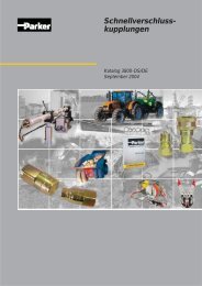
Dimensions<br />
PV063 - 092, metric version<br />
mounting hole for<br />
horse power compensator pilot<br />
or displacement feedback LVDT<br />
78<br />
86 238<br />
26<br />
77.8<br />
66.6<br />
50<br />
252<br />
31<br />
31<br />
drain port L1,<br />
dimensions see L2<br />
20<br />
9<br />
287<br />
max. 308<br />
gage port M; G1/4<br />
43.5 92<br />
optional M12x1.5; ISO 6149-1<br />
(thread options 7 and 8)<br />
or 7/16-20 UNF (thread option 3)<br />
inlet:<br />
flage acc. ISO 6162<br />
DN51; PN200<br />
4xM12, 20 deep<br />
optional 1/2-13UNC-2B<br />
(thread options 3 and 7)<br />
4xM12, 20 deep<br />
optional 1/2-13 UNC-2B<br />
(thread options 3 and 7)<br />
or thread option 4<br />
(M14, 20 deep)<br />
32<br />
outlet:<br />
flage acc. ISO 6162<br />
DN32; PN400<br />
drain port L2; G3/4<br />
optional M27x2; ISO 6149-1<br />
(thread options 7 and 8)<br />
or 1 1/16-12 UNF<br />
(thread option 3)<br />
121<br />
Ø40 k6<br />
43 -0.25<br />
<strong>Axial</strong> <strong>Piston</strong> <strong>Pump</strong><br />
Series PV<br />
9<br />
10<br />
56<br />
11<br />
196<br />
h8 Ø160<br />
key 12x8x80<br />
DIN 6885<br />
Shown is a clockwise rotating pump with standard pressure compensator.<br />
Counter clockwise rotating pumps have inlet, outlet and gauge port reversed.<br />
192 36<br />
Ø160 h8<br />
181<br />
120<br />
thread M12,<br />
28 deep<br />
135<br />
flushing port L3; G1/2<br />
optional M27x2; ISO 6149-1<br />
(thread options 7 and 8)<br />
or 1 1/16-12 UNF<br />
(thread option 3)<br />
200<br />
view X<br />
200<br />
max. 133<br />
The pump shown above has mounting option K<br />
and thru drive option T (prepared for thru drive)<br />
Mounting optional L<br />
splined shaft W40x1.5x15x8f<br />
DIN 5480<br />
18<br />
Parker Hannifin<br />
<strong>Pump</strong> and Motor Division<br />
Chemnitz, Germany
Catalogue HY30-3243/UK<br />
Dimensions<br />
PV063 - 092, SAE version<br />
Shown above is<br />
Mounting option D<br />
Variation with thru drive<br />
287<br />
L<br />
<strong>Axial</strong> <strong>Piston</strong> <strong>Pump</strong><br />
Series PV<br />
Key:<br />
11,11 x 11,11<br />
80 long<br />
K<br />
12<br />
B<br />
Thread:<br />
1/2-13UNC-2B<br />
28 deep<br />
Mounting option E<br />
Splined shaft 13T-8/16 DP,<br />
ANSI B92.1<br />
drive output: splined shaft<br />
W32x1.5x20x8f DIN5480<br />
Thru drive adaptors are available with the following dimensions<br />
Drawing Dimension<br />
A B C D E F G Remark<br />
Thru drive option<br />
A 82,55 10 - - - 100 M8 SAE A 2-Bolt<br />
B 101,6 12 127 89,8 M12 146 M12 SAE B 2/4-Bolt<br />
C 127 14 161,6 114,5 M12 181 M16 SAE C 2/4-Bolt<br />
D 152,4 14 228,5 161,6 M16 - - SAE D 4-Bolt<br />
G 63 10 85 60,1 M8 100 M8 2/4-Bolt<br />
H 80 10 103 72,8 M8 109 M10 2/4-Bolt<br />
J 100 12 125 88,4 M10 140 M12 2/4-Bolt<br />
K 125 12 160 113,1 M12 180 M16 2/4-Bolt<br />
L 160 12 200 141,4 M16 - - 4-Bolt<br />
H<br />
A<br />
D<br />
F<br />
C<br />
E<br />
G<br />
Parker Hannifin<br />
<strong>Pump</strong> and Motor Division<br />
Chemnitz, Germany
Catalogue HY30-3243/UK<br />
Dimensions<br />
PV140 - 180, metric version<br />
106<br />
X<br />
88.9<br />
66.6<br />
mounting hole for<br />
horse power compensator<br />
pilot or LVDT for<br />
displacement feedback<br />
50.8<br />
31.8<br />
105<br />
283<br />
35<br />
35<br />
drain port L1,<br />
dimensions see L2<br />
max. 385<br />
350<br />
4xM12, 20 deep<br />
optional 1/2-13 UNC-2B<br />
(thread options 3 and 7)<br />
or thread option 4<br />
(M14, 22 deep)<br />
32<br />
outlet:<br />
flage acc. ISO 6162<br />
DN32; PN400<br />
20<br />
48<br />
gage port M; G1/4<br />
optional M12x1.5; ISO 6149-1<br />
(thread options 7 and 8)<br />
or 7/16-20 UNF (thread option 3)<br />
147<br />
9<br />
92<br />
78<br />
<strong>Axial</strong> <strong>Piston</strong> <strong>Pump</strong><br />
Series PV<br />
drain port L2; G1<br />
optional M33x2; ISO 6149-1<br />
(thread options 7 and 8)<br />
or 1 5/16-12 UNF<br />
204<br />
(thread option 3)<br />
Ø 50k6 Ø 160h8 53.5-0.25<br />
13<br />
200<br />
9<br />
10<br />
thread M16,<br />
36 deep<br />
key 14x9x75<br />
DIN 6885<br />
158<br />
145<br />
Ø 160h8<br />
Mounting optional L<br />
splined shaft W50x2x24x9g<br />
DIN 5480<br />
200<br />
view X<br />
200<br />
max. 133<br />
233<br />
40<br />
pressure port: 295<br />
flushing port L3; G3/4<br />
suction port: 305<br />
optional M27x2; ISO 6149-1<br />
inlet:<br />
(thread options 7 and 8)<br />
flage acc. ISO 6162<br />
or 1 1/16-12 UNF<br />
DN64; PN160<br />
(thread option 3)<br />
The pump shown above has mounting option K<br />
64<br />
and thru drive option T (prepared for thru drive)<br />
4xM12, 20 deep<br />
optional 1/2-13UNC-2B<br />
(thread options 3 and 7)<br />
Shown is a clockwise rotating pump with standard pressure compensator.<br />
Counter clockwise rotating pumps have inlet, outlet and gauge port reversed.<br />
18<br />
Parker Hannifin<br />
<strong>Pump</strong> and Motor Division<br />
Chemnitz, Germany
Catalogue HY30-3243/UK<br />
Dimensions<br />
PV140 - 180, SAE version<br />
Variation with thru drive<br />
Shown above is mounting option D<br />
415<br />
350<br />
<strong>Axial</strong> <strong>Piston</strong> <strong>Pump</strong><br />
Series PV<br />
Thru drive adaptors are available with the following dimensions<br />
Drawing Dimension<br />
Mounting option E<br />
Splined shaft 15T-8/16 DP,<br />
flat root, side fit<br />
ANSI B92.1<br />
Mounting option F<br />
97<br />
14<br />
B<br />
Thread:<br />
5/8-11UNC-2B<br />
25 deep<br />
Key:<br />
12.7 x 12.7<br />
75 long<br />
Key:<br />
11.11 x 11.11<br />
55 long<br />
Thread:<br />
1/2-13UNC-2B<br />
25 deep<br />
drive output: splined shaft<br />
W40x1.5x25x8f DIN5480<br />
Thru drive option<br />
A 82,55 10 - - - 106 M10 SAE A 2-Bolt<br />
B 101,6 12 127 89,8 M12 146 M12 SAE B 2/4-Bolt<br />
C 127 14 161,6 114,5 M12 181 M16 SAE C 2/4-Bolt<br />
D 152,4 14 228,5 161,6 M16 - - SAE D 4-Bolt<br />
A<br />
H<br />
A B C D E F G Remark<br />
H 80 10 103 72,8 M8 109 M10 2/4-Bolt<br />
J 100 12 125 88,4 M10 140 M12 2/4-Bolt<br />
K 125 12 160 113,1 M12 180 M16 2/4-Bolt<br />
L 160 12 200 141,4 M16 - - 4-Bolt<br />
F<br />
Mounting option G<br />
Splined shaft 13T-8/16 DP,<br />
flat root, side fit<br />
ANSI B92.1<br />
D<br />
C<br />
E<br />
G<br />
Parker Hannifin<br />
<strong>Pump</strong> and Motor Division<br />
Chemnitz, Germany
Catalogue HY30-3243/UK<br />
Dimensions<br />
PV 270, metric version<br />
128<br />
110<br />
120.7<br />
79.4<br />
mounting hole for<br />
horse power compensator<br />
pilot or LVDT for<br />
displacement feedback<br />
69.8<br />
36.5<br />
drain port L1,<br />
dimensions see L2<br />
472.5<br />
max. 510<br />
Ø88<br />
Ø38<br />
403<br />
378<br />
45<br />
45<br />
306<br />
<strong>Axial</strong> <strong>Piston</strong> <strong>Pump</strong><br />
Series PV<br />
drain port L2; G1 1/4<br />
optional M42x2; ISO 6149-1<br />
(thread options 7 and 8)<br />
or 1 5/8-12 UNF<br />
(thread option 3)<br />
15<br />
9<br />
115<br />
gage port M; G1/4<br />
optional M12x1.5; ISO 6149-1 (thread options 7 and 8)<br />
or 7/16-20 UNF (thread option 3)<br />
inlet:<br />
flage acc. ISO 6162<br />
DN89; PN25<br />
4xM16, 32 deep<br />
optional 5/8-11 UNC-2B<br />
(thread options 3 and 7)<br />
4xM16, 32 deep<br />
optional 5/8-11 UNC-2B<br />
(thread options 3 and 7)<br />
outlet:<br />
flage acc. ISO 6162<br />
DN38; PN400<br />
Shown is a clockwise rotating pump with standard pressure compensator.<br />
Counter clockwise rotating pumps have inlet, outlet and gauge port reversed.<br />
60<br />
25<br />
172<br />
Ø65 Ø200<br />
k6 h8<br />
80<br />
69 -0.25<br />
Ø200 h8<br />
9<br />
10<br />
key 18x11x98<br />
DIN 6885<br />
230<br />
thread M20,<br />
42 deep<br />
184<br />
176<br />
22<br />
265<br />
max. 133<br />
250<br />
view X<br />
50<br />
250<br />
flushing port L3; G3/4<br />
optional M27x2; ISO 6149-1<br />
(thread options 7 and 8)<br />
or 1 1/16-12 UNF<br />
(thread option 3)<br />
The pump shown above has mounting option K<br />
and thru drive option T (prepared for thru drive)<br />
Mounting optional L<br />
splined shaft W60x2x28x9g<br />
DIN 5480<br />
Parker Hannifin<br />
<strong>Pump</strong> and Motor Division<br />
Chemnitz, Germany
Catalogue HY30-3243/UK<br />
Dimensions<br />
PV270, SAE version<br />
Variation with thru drive<br />
Shown above is mounting option D<br />
472.5<br />
531.5<br />
<strong>Axial</strong> <strong>Piston</strong> <strong>Pump</strong><br />
Series PV<br />
Thru drive adaptors are available with the following dimensions<br />
Drawing Dimension<br />
88<br />
Thru drive option<br />
A 82,55 8 - - - 106 M10 SAE A 2-Bolt<br />
B 101,6 11 127 89,8 M12 146 M12 SAE B 2/4-Bolt<br />
C 127 13,5 161,6 114,5 M12 181 M16 SAE C 2/4-Bolt<br />
D 152,4 13,5 228,5 161,6 M16 229 M20 SAE D 2/4-Bolt<br />
E 165,1 17 317,5 224,5 M20 - - SAE E 4-Bolt<br />
H 80 8,5 103 72,8 M8 109 M10 2/4-Bolt<br />
J 100 10,5 125 88,4 M10 140 M12 2/4-Bolt<br />
K 125 10,5 160 113,1 M12 180 M16 2/4-Bolt<br />
L 160 13,5 200 141,4 M16 224 M20 2/4-Bolt<br />
M 200 13,5 250 176,8 M20 - - 4-Bolt<br />
16<br />
Key:<br />
12.7 x 12.7<br />
75 long<br />
Ø50.8 -0.05<br />
56.4 ±0.13<br />
15.9<br />
8<br />
89.5<br />
97.5<br />
Ø165.1-0.05<br />
Mounting option E<br />
Splined shaft 15T-8/16 DP,<br />
flat root, side fit<br />
ANSI B92.1<br />
97<br />
Ø165.1-0.05<br />
Thread:<br />
5/8-11UNC-2B<br />
25 deep<br />
drive output: splined shaft<br />
W50x2x24x9g DIN5480<br />
A B C D E F G Remark<br />
B<br />
H<br />
A<br />
112.25<br />
224.5<br />
D F<br />
C<br />
E<br />
Parker Hannifin<br />
<strong>Pump</strong> and Motor Division<br />
Chemnitz, Germany<br />
20.6<br />
224.5<br />
112.25<br />
G
Catalogue HY30-3243/UK<br />
Kits<br />
Mounting kits for multiple pumps, for second pump option<br />
Code <strong>Pump</strong> size<br />
69<br />
MK<br />
Mounting<br />
kit<br />
1 <strong>Pump</strong> size 1: PV016 - PV023<br />
2 <strong>Pump</strong> size 2: PV032 - PV046<br />
3 <strong>Pump</strong> size 3: PV063 - PV092<br />
4 <strong>Pump</strong> size 4: PV140 - PV180<br />
5 <strong>Pump</strong> size 5: PV270<br />
Kit contains positions 30, 69, 84,<br />
85 and 87, see drawing below.<br />
front pump<br />
30 84<br />
PV<br />
<strong>Axial</strong><br />
piston<br />
pump<br />
series PV<br />
85 87<br />
91<br />
BG<br />
Mounting kits for multiple pumps, couplings<br />
Code <strong>Pump</strong> size<br />
1 <strong>Pump</strong> size 1: PV016 - PV023<br />
2 <strong>Pump</strong> size 2: PV032 - PV046<br />
3 <strong>Pump</strong> size 3: PV063 - PV092<br />
4 <strong>Pump</strong> size 4: PV140 - PV180<br />
5 <strong>Pump</strong> size 5: PV270<br />
Kit contains positions 91 (and 92 for<br />
keyed shaft).<br />
MK<br />
Mounting<br />
kit<br />
Size<br />
Code Second pump, SAE<br />
<strong>Axial</strong> <strong>Piston</strong> <strong>Pump</strong><br />
Series PV<br />
Second pump Thread<br />
T Prepared for thru drive option (plugged)<br />
Y SAE AA, diameter 50.8 mm<br />
A SAE A, diameter 82.55 mm<br />
B SAE B, diameter 101.6 mm<br />
C SAE C, diameter 127,mm<br />
D SAE D, diameter 152.4 mm<br />
E SAE E, diameter 165.1 mm<br />
Second pump, metric<br />
G Diameter 63 mm<br />
H Diameter 80 mm<br />
J Diameter 100 mm<br />
K Diameter 125 mm<br />
L Diameter 160 mm<br />
M Diameter 200 mm<br />
PV<br />
<strong>Axial</strong><br />
piston<br />
pump<br />
series PV<br />
BG<br />
92<br />
Size<br />
second pump<br />
17<br />
K<br />
SAE,<br />
splined<br />
Coupling<br />
keyed shaft<br />
(only up to Ø18,<br />
metric)<br />
metric<br />
splined<br />
Seals<br />
Code Seals<br />
N NBR<br />
V FPM<br />
Code Thread<br />
M Metric<br />
S SAE<br />
Code Coupling for metric,<br />
splined shaft DIN 5480<br />
01 N25 x 1.5 x 15<br />
02 N32 x 1.5 x 20<br />
03 N40 x 1.5 x 25<br />
04 N50 x 2 x 24<br />
05 N60 x 2 x 28<br />
Coupling for SAE splined shaft<br />
flat root, side fit<br />
11 SAE A, 9T 16/32<br />
12 SAE-, 11T 16/32<br />
13 SAE B, 13T 16/32<br />
14 SAE B-B, 15T 16/32<br />
15 SAE C, 14T 12/24<br />
16 SAE C-C, 17T 12/24<br />
17 SAE D+E, 13T 8/16<br />
18 SAE F, 15T 8/16<br />
Coupling + adaptor<br />
for keyed shaft<br />
20 Diameter 12 mm<br />
21 Diameter 16 mm<br />
22 Diameter 18 mm<br />
Parker Hannifin<br />
<strong>Pump</strong> and Motor Division<br />
Chemnitz, Germany
Catalogue HY30-3243/UK<br />
Thru Drive, Shaft Load Limitations<br />
Max. transferable torque in [Nm] for different shafts options<br />
<strong>Axial</strong> <strong>Piston</strong> <strong>Pump</strong><br />
Series PV<br />
Shaft code PV063-092 PV140-180 PV270<br />
D 1320 2000 2000<br />
E 1218 2680 2680<br />
F -- 1320 --<br />
G -- 1640 --<br />
K 1150 1900 2850<br />
L 1400 2650 3980<br />
Max. torque transmission 560 1100 1650<br />
cap. for rear mounted pump<br />
Important notice<br />
The max. allowable torque of the individual shaft must<br />
not be exceeded. For 2-pump combinations there is no<br />
problem because PV series offers 100% thru torque. For<br />
3-pump combinations (and more) the limit torque could<br />
be reached or exceeded.<br />
Therefore it is necessary to calculate the torque factor<br />
and compare it with the allowed torque limit factor in the<br />
table.<br />
Required: calculated torque factor<br />
< torque limit factor<br />
To make the necessary calculations easier and more<br />
user friendly it is not required to calculate actual torque<br />
requirements in Nm and compare them with the shaft<br />
limitations. The table on the right shows limit factors that<br />
include material specification, safety factors and conversion<br />
factors.<br />
The total torque factor is represented by the sum of<br />
the individual torque factors of all pumps in the complete<br />
pump combination.<br />
Total torque factor of the combination<br />
= sum of individual torque factors of all pumps<br />
The torque factor of each individual pump is calculated<br />
by multiplying the max. operating pressure p of the pump<br />
(in bar) with the max. displacement Vg of the pump (in<br />
cm³/rev).<br />
Torque factor of any pump<br />
= p x Vg<br />
18<br />
<strong>Pump</strong> Shaft Torque limit factor<br />
D 77280<br />
PV063-092 E 72450<br />
K 67620<br />
L 83720<br />
D 118400<br />
E 158760<br />
PV140-180 F 78750<br />
G 97650<br />
K 113400<br />
L 157500<br />
D 119000<br />
PV270 E 159700<br />
K 170100<br />
L 236250<br />
Parker Hannifin<br />
<strong>Pump</strong> and Motor Division<br />
Chemnitz, Germany
Catalogue HY30-3243/UK<br />
Compensators Dimensions<br />
<strong>Axial</strong> <strong>Piston</strong> <strong>Pump</strong><br />
Series PV<br />
Dimensions standard pressure compensator, code ...FDS, ...FHS, ...FWS<br />
172 46<br />
43,5<br />
41<br />
43,5<br />
A<br />
P<br />
P<br />
A<br />
T<br />
pump axis<br />
Dimensions remote pressure and load sensing compensator, codes ...FRC, ...FFC<br />
pump axis<br />
T<br />
172<br />
37,5<br />
remote control port p P (code ...FRC)<br />
resp. LS port p F (code ...FFC)<br />
Dimensions horse power control cartridge and displacement sensor<br />
pump body (case)<br />
19<br />
72<br />
45<br />
45<br />
45<br />
46<br />
41<br />
73<br />
Parker Hannifin<br />
<strong>Pump</strong> and Motor Division<br />
Chemnitz, Germany
Catalogue HY30-3243/UK<br />
Compensators Dimensions<br />
<strong>Axial</strong> <strong>Piston</strong> <strong>Pump</strong><br />
Series PV<br />
Dimensions compensator with NG6-interface for pilot valves, codes ...FR1, ...FR2, ...FF1<br />
43,5<br />
P<br />
43,5<br />
A<br />
pump axis<br />
T<br />
172<br />
74.5<br />
Compensators with code ...FR1 have no remote control port.<br />
Dimensions compensator with mounted pressure pilot valve, codes ...FRP, ...FFP<br />
pump axis<br />
172<br />
remote control port p P (code ...FR2 only)<br />
resp. LS port p F (code ...FF1)<br />
20<br />
53<br />
pilot valve:<br />
PVAC1PC**S35;<br />
** for threads and<br />
seals option<br />
Compensators with codes ...FRD, ...FFD have a proportional pressure pilot valve type PVACPPC**35 mounted;<br />
Compensators with codes ...FRK, ...FFK have a proportional pressure pilot valve type PVACREC**35 mounted;<br />
** for threads and seals option;<br />
Dimensions of pilot valves see following pages.<br />
Dimensions for horse power compensator *L* and *C* are identical to FR* and FF*.<br />
45<br />
72<br />
45<br />
82<br />
87<br />
41<br />
41<br />
Parker Hannifin<br />
<strong>Pump</strong> and Motor Division<br />
Chemnitz, Germany
Catalogue HY30-3243/UK<br />
Compensators Dimensions<br />
<strong>Axial</strong> <strong>Piston</strong> <strong>Pump</strong><br />
Series PV<br />
Dimensions two-spool load sensing compensator, code ...FT1, ...FT2, ...FTP<br />
128<br />
49<br />
82<br />
129<br />
49<br />
82<br />
43,5<br />
pump axis<br />
172<br />
43,5 78<br />
172<br />
21,5<br />
104,5<br />
pressure<br />
control stage<br />
65<br />
21,5<br />
65<br />
21<br />
LS port p F<br />
Dimensions two-spool load sensing compensator with proportional pressure pilot valve, code ...FTK<br />
LS port p F<br />
pump axis<br />
remote pressure<br />
control port p P<br />
(code ...FT2 only)<br />
pressure pilot valve<br />
PVAC1PT**S35<br />
(code ...FTP only)<br />
displacement<br />
control stage<br />
pilot valve:<br />
PVACRET**35 for code ...FTK,<br />
** for threads and seals option<br />
105<br />
proportional pressure<br />
pilot valve<br />
140<br />
pressure<br />
control stage<br />
65<br />
24<br />
24<br />
displacement<br />
control stage<br />
Parker Hannifin<br />
<strong>Pump</strong> and Motor Division<br />
Chemnitz, Germany
Catalogue HY30-3243/UK<br />
Compensators Dimensions<br />
Dimensions proportional displacement control, code ...FPV<br />
133<br />
95<br />
48<br />
94,5<br />
pump axis<br />
111<br />
222<br />
24<br />
91<br />
107<br />
71<br />
<strong>Axial</strong> <strong>Piston</strong> <strong>Pump</strong><br />
Series PV<br />
Dimensions proportional p/Q control, codes ...UPR, ...UPK, ...UPM<br />
pump axis<br />
pilot valve:<br />
PVACREM**35 for code ...UPK, UPM,<br />
** for threads and seals option<br />
22<br />
pressure pilot valve<br />
(codes ...UPK, ...UPM<br />
only)<br />
pressure sensor<br />
(code ...UPM only)<br />
pressure<br />
control stage<br />
elbow manifold<br />
Parker Hannifin<br />
<strong>Pump</strong> and Motor Division<br />
Chemnitz, Germany<br />
displacement<br />
control stage
Catalogue HY30-3243/UK<br />
Pressure Compensators<br />
Standard pressure compensator, code F*S<br />
The standard pressure compensator adjusts the pump<br />
displacement according to the actual need of the system<br />
in order to keep the pressure constant.<br />
As long as the system pressure at outlet port P is lower<br />
than the set pressure (set as spring preload of the compensator<br />
spring) the working port A of the compensator<br />
valve is connected to the case drain and the piston area<br />
is unloaded. Bias spring and system pressure on the annulus<br />
area keep the pump at full displacement.<br />
When the system pressure reaches the set pressure<br />
the compensator valve spool connects port P1 to A and<br />
builds up a pressure at the servo piston resulting in a<br />
downstroking of the pump. The displacement of the pump<br />
is controlled in order to match the flow requirement of<br />
the system.<br />
Remote pressure compensator, code FRC<br />
While at the standard pressure compensator the pressure<br />
is set directly at the compensator spring, the setting of the<br />
remote pressure compensator can be achieved by any<br />
suitable pilot pressure valve connected to pilot port PP .<br />
The pilot flow supply is internal through the valve spool.<br />
The pilot flow is 1 - 1.5 l/min. The pilot valve can be installed<br />
remote from the pump in some distance. That allows pressure<br />
setting e. g. from the control panel of the machine.<br />
The remote pressure compensator typically responds<br />
faster and more precisely than the standard pressure<br />
compensator and is able to solve instability problems<br />
that may occur with a standard pressure compensator<br />
in critical applications.<br />
The pressure pilot valve can also be electronically<br />
controlled (proportional pressure valve) or combined<br />
with a directional control valve for low pressure standby<br />
operation.<br />
Remote pressure compensator, code FR1<br />
Version *FR1 of the remote pressure compensator provides<br />
on its top side an interface NG6, DIN 24340 (CETOP<br />
03 at RP35H, NFPA D03).<br />
This interface allows a direct mounting of a pilot valve<br />
(see option *FRP and *FRK page 7). Beside manual or<br />
electrohydraulic operated valves it is also possible to<br />
mount complete multiple pressure circuits directly on<br />
the compensator body. Parker offers a variety of these<br />
compensator accessories ready to install.<br />
All remote pressure compensators have a factory setting<br />
of 15 bar differential pressure. With this setting, the<br />
controlled pressure at the pump outlet is higher than the<br />
pressure controlled by the pilot valve.<br />
<strong>Axial</strong> <strong>Piston</strong> <strong>Pump</strong><br />
Series PV<br />
23<br />
Code FRP<br />
= included FR1<br />
Parker Hannifin<br />
<strong>Pump</strong> and Motor Division<br />
Chemnitz, Germany
Catalogue HY30-3243/UK<br />
Load-Sensing Compensators<br />
Load-Sensing compensator, code FFC<br />
The load-sensing compensator has an external pilot pressure<br />
supply. Factory setting for the differential pressure<br />
is 10 bar. The input signal to the compensator is the differential<br />
pressure at a main stream resistor. A load-sensing<br />
compensator represents mainly a flow control for the<br />
pump output flow, because the compensator keeps the<br />
pressure drop at the main stream resistor constant.<br />
A variable input speed or a varying load(-pressure) has<br />
consequently no influence on the output flow of the pump<br />
and the speed of the actuator.<br />
By adding a pilot orifice (Ø 0.8 mm) and a pressure pilot<br />
valve pressure compensation can be added to the flow<br />
control function. See the circuit diagram below, left.<br />
Load-Sensing<br />
compensator<br />
code FFC<br />
external orifice and<br />
pressure pilot valve<br />
Shown above is load-sensing compensator, code<br />
FF1 with an NG6 interface on top of the control valve.<br />
That allows direct mounting of a pilot valve for pressure<br />
compensation (see option *FFP and *FFK page 7). This<br />
version includes the pilot orifice.<br />
Due to the interaction of flow and pressure compensation<br />
this package has not the ”ideal” control characteristic. The<br />
deviation is caused by the pilot valves characteristic.<br />
If a more accurate pressure compensation is required, the<br />
2-valve load-sensing compensator code FT1 can be<br />
used. The circuit diagram of this version is shown left.<br />
Here the interaction of the two control functions is avoided<br />
by using two separate control valves for flow and pressure<br />
compensation.<br />
The 2-valve compensator is equipped with an interface<br />
NG6 on the compensators top side.<br />
<strong>Axial</strong> <strong>Piston</strong> <strong>Pump</strong><br />
Series PV<br />
24<br />
PM<br />
L<br />
P L<br />
S L<br />
Code FFP<br />
T P<br />
T<br />
P<br />
P 1<br />
P1<br />
A<br />
A<br />
PF<br />
2-valve Load-Sens.<br />
compensator with<br />
interface NG6 for<br />
accessories<br />
code FT1<br />
Q<br />
Q<br />
= included FF1<br />
= included<br />
Parker Hannifin<br />
<strong>Pump</strong> and Motor Division<br />
Chemnitz, Germany<br />
p
Catalogue HY30-3243/UK<br />
Power Compensators<br />
Hydraulic-mechanical power compensator<br />
The hydraulic-mechanical power compensator consists of<br />
a modified remote pressure compensator (Code *L*) or<br />
of a modified load-sensing compensator (Code *C*) and<br />
a pilot valve. This pilot valve is integrated into the pump<br />
and is adjusted by a cam sleeve. The cam sleeve has a<br />
contour that is designed and machined for the individual<br />
displacement and the nominal power setting.<br />
At a large displacement the opening pressure (given by the<br />
cam sleeve diameter) is lower than at small displacements.<br />
This makes the pump compensate along a constant power<br />
(torque) curve (see diagrams on opposite page).<br />
For all nominal powers of standard electrical motors Parker<br />
offers a dedicated cam sleeve. The exchange of this cam<br />
sleeve (e. g.: to change power setting) can easily be done<br />
without disassembly of the pump.<br />
On top of that an adjustment of the power setting can be<br />
done within certain limits by adjusting the preload of the<br />
pilot control cartridge spring . That allows an adjustment<br />
of a constant power setting for other than the nominal<br />
speeds (1500 min -1 ) or for other powers.<br />
P<br />
P<br />
P A<br />
P P P A P<br />
P P<br />
<strong>Axial</strong> <strong>Piston</strong> <strong>Pump</strong><br />
Series PV<br />
25<br />
Ordering code for the power option<br />
The first digit designates the power setting:<br />
Code G = 11.0 kW etc. up to<br />
Code 3 = 132.0 kW<br />
The second digit designates the pilot flow source:<br />
Code L internal pilot pressure, remote pressure function.<br />
Code C external pilot pressure, combines power compensation<br />
with load-sensing compensation.<br />
The third digit designates the possibility to adjust the<br />
overriding pressure compensation:<br />
Code A comes with a top side NG6/D03 interface on<br />
the control valve to mount any suitable pilot<br />
valve or Parker pump accessories.<br />
Code B has a threaded pilot port P p (G1/4) to connect<br />
a remote pilot valve with piping.<br />
Code C includes a pilot valve for manual pressure<br />
adjustment. Max. setting: 350 bar.<br />
Code *LC Code *LB<br />
P<br />
P<br />
P<br />
P<br />
Code *CC<br />
A<br />
A<br />
P<br />
P<br />
Note:<br />
If *CB is connected to an<br />
external pilot valve and<br />
0.8 mm orifice ,<br />
the orifice in port P F has to<br />
be removed.<br />
P<br />
P<br />
Ø0,8<br />
P A<br />
P P P A P<br />
P<br />
P<br />
Code *CB<br />
A<br />
A<br />
P P<br />
Parker Hannifin<br />
<strong>Pump</strong> and Motor Division<br />
Chemnitz, Germany<br />
P<br />
P
Catalogue HY30-3243/UK<br />
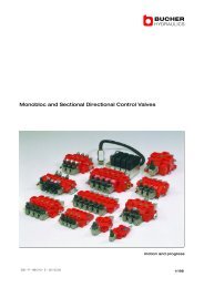
Power Compensators, Diagrams<br />
The graphs below show typical power curves,<br />
collected during following conditions:<br />
Speed : n = 1500 rev/min<br />
Temperature : t = 50 °C<br />
Fluid : HLP, ISO VG46<br />
Viscosity : ν = 46 mm2 /s at 40 °C<br />
Flow rate Q [l/min] Flow rate Q [l/min]<br />
140<br />
120<br />
100<br />
80<br />
60<br />
40<br />
20<br />
210<br />
200<br />
180<br />
160<br />
140<br />
120<br />
100<br />
80<br />
60<br />
40<br />
22 kW<br />
18,5 kW<br />
15 kW<br />
11 kW<br />
30 kW<br />
22 kW<br />
18,5 kW<br />
37 kW<br />
30 kW<br />
45 kW<br />
55 kW<br />
37 kW<br />
75 kW<br />
55 kW<br />
45kW<br />
90kW<br />
PV140<br />
PV092<br />
PV080<br />
PV063<br />
20<br />
0<br />
0 50100 150 200 250 300 350<br />
Pressure p [bar]<br />
<strong>Axial</strong> <strong>Piston</strong> <strong>Pump</strong><br />
Series PV<br />
0 0<br />
0 50100 150 200 250 300 350<br />
0 50100 150 200 250 300 350<br />
Pressure p [bar] Pressure p [bar]<br />
26<br />
Flow rate Q [l/min]<br />
Flow rate Q [l/min]<br />
300<br />
270<br />
240<br />
210<br />
180<br />
150<br />
120<br />
90<br />
60<br />
30<br />
425<br />
350<br />
300<br />
250<br />
200<br />
150<br />
100<br />
50<br />
22 kW<br />
30 kW<br />
45 kW<br />
37 kW<br />
55 kW<br />
75 kW<br />
55 kW<br />
45 kW<br />
37 kW<br />
90kW<br />
90kW<br />
75 kW<br />
110 kW<br />
132 kW<br />
110 kW<br />
Parker Hannifin<br />
<strong>Pump</strong> and Motor Division<br />
Chemnitz, Germany<br />
PV180<br />
PV270<br />
0<br />
0 50100 150 200 250 300 350<br />
Pressure p [bar]
Catalogue HY30-3243/UK<br />
Proportional displacement control, code FPV<br />
The proportional displacement control allows the adjustment<br />
of the pumps output flow with an electrical input<br />
signal.<br />
The actual displacement of the pump is monitored by an<br />
LVDT and compared with the commanded displacement<br />
in an electronic control module PQDXXA. The command<br />
is given as an electrical input signal (0 - 10 V or 0 resp.<br />
4 - 20 mA) from the supervising machine control. The<br />
command can also be provided by a potentiometer. The<br />
electronic control module offers a stabilized 10 V source<br />
to supply the potentiometer.<br />
The electronic module compares permanently the input<br />
command and the actual displacement by powering the<br />
proportional solenoid of the control valve. A deviation from<br />
the commanded displacement leads to a modulation of<br />
the input current to the solenoid. The control valve then<br />
changes the control pressure (port A) until the correct<br />
displacement is adjusted.<br />
Version FPV of the proportional control does not provide<br />
a pressure compensation. The hydraulic circuit must be<br />
protected by a pressure relief valve.<br />
Proportional displacement control with overriding<br />
pressure control, codes UPR, UPK and UPM<br />
Compensator version *UPR provides electro- hydraulic<br />
displacement control and pressure stage mounted on<br />
elbow manifold. The elbow manifold provides NG6/D03<br />
interface on top to mount a pressure pilot valve (not included<br />
in *UPR).<br />
When using a proportional pressure pilot valve an<br />
electro-hydraulic p/Q control can be realized. The proportional<br />
pressure pilot valve PVACRE..35 is included in<br />
compensator version *UPK. By using the digital module<br />
PQDXXA-Z00 it is possible to control the displacement<br />
proportionally with overriding open loop proportional<br />
pressure control.<br />
Compensator version *UPM is completed by a pressure<br />
transducer Parker SCP 8181 CE. In combination with control<br />
module PQDXXA-Z00 a closed loop pressure control<br />
of pump outlet pressure is available. The control module<br />
also offers an electronic power limiter in addition to closed<br />
loop pressure control with this compensator option.<br />
Note:<br />
Minimum pump pressure (appr. 20 to 30 bar) depends<br />
on system and pilot valve used. <strong>Pump</strong> cannot fully<br />
downstroke if system pressure is below that level.<br />
<strong>Axial</strong> <strong>Piston</strong> <strong>Pump</strong><br />
Series PV<br />
27<br />
UP<br />
UQ<br />
P M<br />
U Q<br />
P M<br />
U P<br />
U Q<br />
P L<br />
S L<br />
L<br />
P L<br />
S L<br />
p1 L<br />
PM P L<br />
S L<br />
T P<br />
T<br />
P<br />
T<br />
L P1 A<br />
U<br />
s<br />
U<br />
s<br />
U<br />
s<br />
P1<br />
P1<br />
U<br />
p<br />
P 1<br />
P 1<br />
P 1<br />
A<br />
A<br />
T P pP P<br />
D P<br />
D B1 DB2<br />
A<br />
A<br />
A<br />
Q<br />
Q<br />
Q<br />
U Q<br />
U Q<br />
U Q<br />
U P<br />
U P<br />
Parker Hannifin<br />
<strong>Pump</strong> and Motor Division<br />
Chemnitz, Germany<br />
p<br />
= included FPV<br />
p<br />
included UPR<br />
additionally at UPK<br />
p<br />
= included UPM
Catalogue HY30-3243/UK<br />
Electronic Module PQDXXA (digital)<br />
The digital control module code PQDXXA-Z00 is designed<br />
for rail mounting.<br />
Features<br />
• Digital control circuit<br />
• Parameter setting via RS-232 interface<br />
• All settings (ramps, MIN/MAX, control parameters) can<br />
be stored digitally and recalled from a PC to duplicate<br />
settings to other modules<br />
• Ramp time up to 60 seconds<br />
• Compatible to the relevant european EMC specifications<br />
• Easy to use PC based setup software<br />
• Covers all displacements from 16 to 270 cm³/rev<br />
• Covers all functions: displacement control, displacement<br />
control with open loop pressure control, displacement<br />
control with closed loop pressure control and displacement<br />
control with closed loop pressure control and<br />
electronic power limitation.<br />
Ordering code<br />
Technical data<br />
PQD XX A<br />
Digital control<br />
module for p/Q<br />
control<br />
For all frame<br />
sizes series PV<br />
<strong>Axial</strong> <strong>Piston</strong> <strong>Pump</strong><br />
Series PV<br />
28<br />
Version A<br />
Z00<br />
Option<br />
Mounting style Snap-on mounting for EN50022 rail<br />
Body material Polycarbonate<br />
Inflammation class V2...V0 acc. UL 94<br />
Mounting position any<br />
Env. temperature range [°C] -20...+55<br />
Protection class IP 20 acc. DIN 40 050<br />
Weight [g] 160<br />
Duty ratio [%] 100<br />
Supply voltage [V] 18...30VDC, ripple
Catalogue HY30-3243/UK<br />
General Installation Information<br />
Programming software<br />
The programming of the p/Q control module is done in an<br />
easy to learn mode. To select the pump model and size<br />
and to set the control paramters the program ProPVplus<br />
must be started. This program runs under WINDOWS ®<br />
95 and higher.<br />
The latest version of this software can be downloaded at<br />
the following internet address:<br />
http://www.parker.com/euro_hcd<br />
The software offers the following features:<br />
A TERMINAL window to set or read out the control parameters<br />
of the module. Settings as well as comments entered<br />
in the terminal window can be stored also in RTFformat<br />
(opens e. g. under WORD or other text editors)<br />
A MONITOR window allows to display process variables<br />
in numerical format.<br />
Diagrams<br />
100% 100%<br />
0<br />
0<br />
<strong>Axial</strong> <strong>Piston</strong> <strong>Pump</strong><br />
Series PV<br />
Typical static characteristic Typical dynamic characteristic<br />
Displacement<br />
Response time (50-300 bar)<br />
Input command +10 V<br />
0<br />
0<br />
TA TR Time t<br />
<strong>Pump</strong> size TA [ms] TR [ms]<br />
PV092 90 90<br />
PV180 170 170<br />
PV270 250 250<br />
29<br />
An OSZILLOSKOP window displays process variables<br />
as curves. The oscilloscope offers a start - stop function.<br />
The images can be saved and stored e. g. for import into<br />
other programs.<br />
Features<br />
• Display and documentation of parameter sets<br />
• Save ond reload of optimized parameter sets<br />
• Offers oscilloscope function for easy performance evaluation<br />
and optimization<br />
• Pre-optimized parameter sets for all PVplus piston<br />
pump<br />
• Sizes already in E 2 PROM memory<br />
Displacement<br />
Parker Hannifin<br />
<strong>Pump</strong> and Motor Division<br />
Chemnitz, Germany
Catalogue HY30-3243/UK<br />
Accessories Compensator<br />
PV<br />
For<br />
PV pump<br />
series<br />
AC<br />
Accessories<br />
for<br />
compensators<br />
Code Function<br />
1P Max. pressure relief<br />
1E 1 pressure,<br />
electrical unloading<br />
2P 2 pressures,<br />
electrical selection<br />
2 pressures + stands<br />
2E electrical selection<br />
low pressure default<br />
2 pressures + stands<br />
2M electrical selection<br />
stand by default<br />
Dimensions<br />
PVAC1P*<br />
<strong>Axial</strong> <strong>Piston</strong> <strong>Pump</strong><br />
Series PV<br />
Function Mounting<br />
bolts<br />
Threads Seals Adjustment Solenoid<br />
Code Threads<br />
M Metric<br />
S SAE / UNC<br />
Code Mounting bolts<br />
Code Seals<br />
N NBR<br />
V FPM<br />
C For single compensators type R or F<br />
S Without bolts<br />
M For code UP*/MT* + DS 45<br />
U For code UP* + DS 42<br />
Compensator accessory only available on pump, not as single items<br />
(replacement kit see spare part list PVI-PVAC-UK).<br />
30<br />
Code Adjustment<br />
S Spindle<br />
with lock nut<br />
PVAC2P* PVAC2M*/PVAC2E*<br />
High<br />
pressure<br />
Adjustment<br />
Code S<br />
DC solenoid 205<br />
AC solenoid 190<br />
Low<br />
pressure<br />
48<br />
133<br />
PVAC1E*<br />
High<br />
pressure<br />
DC solenoid 205<br />
AC solenoid 190<br />
DC solenoid 241<br />
AC solenoid 211<br />
Solenoid<br />
accessories<br />
35<br />
Nominal<br />
pressure<br />
350 bar<br />
Code Solenoid accessories<br />
omit For function 1P<br />
C Conduit box<br />
with free wires<br />
W DIN plug socket<br />
without plug<br />
Code Solenoid voltage<br />
omit For function 1P<br />
Y 110V/50Hz - 120V/60Hz<br />
T 220V/50Hz - 240V/60Hz<br />
J 24V DC<br />
Low<br />
pressure<br />
48<br />
Parker Hannifin<br />
<strong>Pump</strong> and Motor Division<br />
Chemnitz, Germany<br />
133<br />
48<br />
133
Catalogue HY30-3243/UK<br />
Accessories Compensator<br />
<strong>Axial</strong> <strong>Piston</strong> <strong>Pump</strong><br />
Series PV<br />
Schematics PVAC1P* Schematics PVAC1E*<br />
Schematics PVAC2P* Schematics PVAC2M*/PVAC2E*<br />
31<br />
*2M*<br />
Parker Hannifin<br />
<strong>Pump</strong> and Motor Division<br />
Chemnitz, Germany
Catalogue HY30-3243/UK<br />
Accessories Compensator<br />
Ordering code proportional pressure control valve<br />
PV<br />
<strong>Pump</strong><br />
series PV<br />
AC<br />
Accessories<br />
for controller<br />
Code Mounting bolts/<br />
ports<br />
C For single controller<br />
type *MR* or *MF*<br />
T For double valve contr. type *FT*<br />
S Without bolts<br />
M For code UP*/MT* + DS 45<br />
U For code UP* + DS 42<br />
RE<br />
Prop.<br />
pressure<br />
valve<br />
Proportional pressure control valve<br />
Proportional pressure pilot valves of series PVACRE*<br />
(RE06...) are powered by external electronic modules<br />
<strong>Axial</strong> <strong>Piston</strong> <strong>Pump</strong><br />
Series PV<br />
Schematic PVACRE* Dimensions PVACRE*<br />
Example for PVACRE* mounted<br />
Mounting<br />
bolts<br />
32<br />
Thread<br />
option<br />
Code Thread option<br />
M Metric<br />
S SAE / UNC<br />
Seal<br />
Nominal<br />
pressure<br />
Code Nominal pressure<br />
35 350 bar<br />
42 420 bar<br />
Code Seal<br />
N NBR<br />
V FPM<br />
(see catalogue HY11-3500 for reference). They allow an<br />
infinite electronic adjustment of the pumps compensating<br />
pressure.<br />
Parker Hannifin<br />
<strong>Pump</strong> and Motor Division<br />
Chemnitz, Germany
Catalogue HY30-3243/UK<br />
Notes<br />
<strong>Axial</strong> <strong>Piston</strong> <strong>Pump</strong><br />
Series PV<br />
33<br />
Parker Hannifin<br />
<strong>Pump</strong> and Motor Division<br />
Chemnitz, Germany
Catalogue HY30-3243/UK<br />
Notes<br />
<strong>Axial</strong> <strong>Piston</strong> <strong>Pump</strong><br />
Series PV<br />
34<br />
Parker Hannifin<br />
<strong>Pump</strong> and Motor Division<br />
Chemnitz, Germany
Catalogue HY30-3243/UK<br />
!<br />
<strong>Axial</strong> <strong>Piston</strong> <strong>Pump</strong><br />
Series PV<br />
WARNING<br />
FAILURE OR IMPROPER SELECTION OR IMPROPER USE OF THE PRODUCTS AND/OR SYSTEMS DESCRIBED<br />
HEREIN OR RELATED ITEMS CAN CAUSE DEATH, PERSONAL INJURY AND PROPERTY DAMAGE.<br />
This document and other information from Parker Hannifin Corporation, its subsidiaries and authorized distributors provide<br />
product and/or system options for further investigation by users having technical expertise. It is important that you analyze all<br />
aspects of your application, including consequences of any failure, and review the information concerning the product or system<br />
in the current product catalogue. Due to the variety of operating conditions and applications for these products or systems,<br />
the user, through its own analysis and testing, is solely responsible for making the final selection of the products and systems<br />
and assuring that all performance, safety and warning requirements of the application are met.<br />
The products described herein, including without limitation, product features, specifications, designs, availability and pricing, are<br />
subject to change by Parker Hannifin Corporation and its subsidiaries at any time without notice.<br />
Offer of Sale<br />
Please contact your Parker representation for a detailed ”Offer of Sale”.<br />
35<br />
Parker Hannifin<br />
<strong>Pump</strong> and Motor Division<br />
Chemnitz, Germany
Parker Worldwide<br />
AE – UAE, Dubai<br />
Tel: +971 4 8875600<br />
parker.me@parker.com<br />
AR – Argentina, Buenos Aires<br />
Tel: +54 3327 44 4129<br />
AT – Austria, Wiener Neustadt<br />
Tel: +43 (0)2622 23501-0<br />
parker.austria@parker.com<br />
AT – Eastern Europe,<br />
Wiener Neustadt<br />
Tel: +43 (0)2622 23501 970<br />
parker.easteurope@parker.com<br />
AU – Australia, Castle Hill<br />
Tel: +61 (0)2-9634 7777<br />
AZ – Azerbaijan, Baku<br />
Tel: +994 50 2233 458<br />
parker.azerbaijan@parker.com<br />
BE/LX – Belgium, Nivelles<br />
Tel: +32 (0)67 280 900<br />
parker.belgium@parker.com<br />
BR – Brazil, Cachoeirinha RS<br />
Tel: +55 51 3470 9144<br />
BY – Belarus, Minsk<br />
Tel: +375 17 209 9399<br />
parker.belarus@parker.com<br />
CA – Canada, Milton, Ontario<br />
Tel: +1 905 693 3000<br />
CH – Switzerland, Etoy<br />
Tel: +41 (0) 21 821 02 30<br />
parker.switzerland@parker.com<br />
CN – China, Shanghai<br />
Tel: +86 21 5031 2525<br />
CZ – Czech Republic, Klecany<br />
Tel: +420 284 083 111<br />
parker.czechrepublic@parker.com<br />
DE – Germany, Kaarst<br />
Tel: +49 (0)2131 4016 0<br />
parker.germany@parker.com<br />
DK – Denmark, Ballerup<br />
Tel: +45 43 56 04 00<br />
parker.denmark@parker.com<br />
ES – Spain, Madrid<br />
Tel: +34 902 33 00 01<br />
parker.spain@parker.com<br />
FI – Finland, Vantaa<br />
Tel: +358 (0)20 753 2500<br />
parker.finland@parker.com<br />
FR – France, Contamine s/Arve<br />
Tel: +33 (0)4 50 25 80 25<br />
parker.france@parker.com<br />
© 2008 Parker Hannifin Corporation. All rights reserved.<br />
GR – Greece, Athens<br />
Tel: +30 210 933 6450<br />
parker.greece@parker.com<br />
HK – Hong Kong<br />
Tel: +852 2428 8008<br />
HU – Hungary, Budapest<br />
Tel: +36 1 220 4155<br />
parker.hungary@parker.com<br />
IE – Ireland, Dublin<br />
Tel: +353 (0)1 466 6370<br />
parker.ireland@parker.com<br />
IN – India, Mumbai<br />
Tel: +91 22 6513 7081-85<br />
IT – Italy, Corsico (MI)<br />
Tel: +39 02 45 19 21<br />
parker.italy@parker.com<br />
JP – Japan, Fujisawa<br />
Tel: +(81) 4 6635 3050<br />
KR – South Korea, Seoul<br />
Tel: +82 2 559 0400<br />
KZ – Kazakhstan, Almaty<br />
Tel: +7 7272 505 800<br />
parker.easteurope@parker.com<br />
LV – Latvia, Riga<br />
Tel: +371 6 745 2601<br />
parker.latvia@parker.com<br />
MX – Mexico, Apodaca<br />
Tel: +52 81 8156 6000<br />
MY – Malaysia, Subang Jaya<br />
Tel: +60 3 5638 1476<br />
NL – The Netherlands,<br />
Oldenzaal<br />
Tel: +31 (0)541 585 000<br />
parker.nl@parker.com<br />
NO – Norway, Ski<br />
Tel: +47 64 91 10 00<br />
parker.norway@parker.com<br />
NZ – New Zealand, Mt Wellington<br />
Tel: +64 9 574 1744<br />
PL – Poland, Warsaw<br />
Tel: +48 (0)22 573 24 00<br />
parker.poland@parker.com<br />
PT – Portugal, Leca da Palmeira<br />
Tel: +351 22 999 7360<br />
parker.portugal@parker.com<br />
RO – Romania, Bucharest<br />
Tel: +40 21 252 1382<br />
parker.romania@parker.com<br />
Parker Hannifin Ltd.<br />
Tachbrook Park Drive<br />
Tachbrook Park, Warwick CV34 6TU<br />
United Kingdom<br />
Tel.: +44 (0) 1926 317 878<br />
Fax: +44 (0) 1926 317 855<br />
www.parker.com<br />
RU – Russia, Moscow<br />
Tel: +7 495 645-2156<br />
parker.russia@parker.com<br />
SE – Sweden, Spånga<br />
Tel: +46 (0)8 59 79 50 00<br />
parker.sweden@parker.com<br />
SG – Singapore<br />
Tel: +65 6887 6300<br />
SK – Slovakia, Banská Bystrica<br />
Tel: +421 484 162 252<br />
parker.slovakia@parker.com<br />
SL – Slovenia, Novo Mesto<br />
Tel: +386 7 337 6650<br />
parker.slovenia@parker.com<br />
TH – Thailand, Bangkok<br />
Tel: +662 717 8140<br />
TR – Turkey, Istanbul<br />
Tel: +90 216 4997081<br />
parker.turkey@parker.com<br />
TW – Taiwan, Taipei<br />
Tel: +886 2 2298 8987<br />
UA – Ukraine, Kiev<br />
Tel +380 44 494 2731<br />
parker.ukraine@parker.com<br />
UK – United Kingdom,<br />
Warwick<br />
Tel: +44 (0)1926 317 878<br />
parker.uk@parker.com<br />
US – USA, Cleveland<br />
(industrial)<br />
Tel: +1 216 896 3000<br />
US – USA, Lincolnshire<br />
(mobile)<br />
Tel: +1 847 821 1500<br />
VE – Venezuela, Caracas<br />
Tel: +58 212 238 5422<br />
ZA – South Africa,<br />
Kempton Park<br />
Tel: +27 (0)11 961 0700<br />
parker.southafrica@parker.com<br />
European Product Information Centre<br />
Free phone: 00 800 27 27 5374<br />
(from AT, BE, CH, CZ, DE, DK, EE, ES, FI, FR,<br />
IE, IT, NL, NO, PL, RU, SE, SK, UK, ZA)<br />
Catalogue HY30-3243/UK. POD 02/2008 PC<br />
HYGE Ed. 2008-04-04<br />
Your local authorized Parker distributor