Air Oil Coolers Oiltech LOC Datasheet
Air Oil Coolers Oiltech LOC Datasheet
Air Oil Coolers Oiltech LOC Datasheet

Create successful ePaper yourself
Turn your PDF publications into a flip-book with our unique Google optimized e-Paper software.
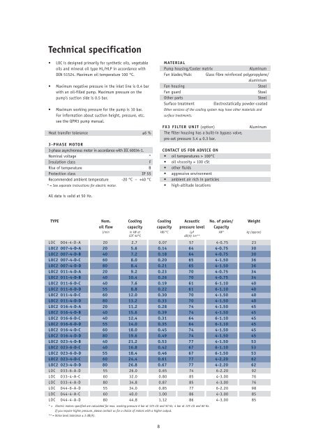
Technical specification<br />
• <strong>LOC</strong> is designed primarily for synthetic oils, vegetable<br />
oils and mineral oil type HL/HLP in accordance with<br />
DIN 51524. Maximum oil temperature 100 °C.<br />
• Maximum negative pressure in the inlet line is 0.4 bar<br />
with an oil-filled pump. Maximum pressure on the<br />
pump’s suction side is 0.5 bar.<br />
• Maximum working pressure for the pump is 10 bar.<br />
For information about suction height, pressure, etc.<br />
see the QPM3 pump manual.<br />
Heat transfer tolerance ±6 %<br />
3-PHASE MOTOR<br />
3-phase asynchronous motor in accordance with IEC 60034-1.<br />
Nominal voltage *<br />
Insulation class F<br />
Rise of temperature B<br />
Protection class IP 55<br />
Recommended ambient temperature<br />
* = See separate instructions for electric motor.<br />
-20 °C – +40 °C<br />
All data is valid at 50 Hz.<br />
<strong>LOC</strong> 004-4-D-A 20 2.7 0.07 57 4-0.75 23<br />
<strong>LOC</strong>2 007-4-D-A 20 5.6 0.14 64 4-0.75 30<br />
<strong>LOC</strong>2 007-4-D-B 40 7.2 0.18 64 4-0.75 30<br />
<strong>LOC</strong>2 007-4-D-C 60 8.0 0.20 65 4-1.50 36<br />
<strong>LOC</strong>2 007-4-D-D 80 8.4 0.21 65 4-1.50 36<br />
<strong>LOC</strong>2 011-4-D-A 20 9.2 0.23 70 4-0.75 34<br />
<strong>LOC</strong>2 011-4-D-B 40 10.4 0.26 70 4-0.75 34<br />
<strong>LOC</strong>2 011-6-D-C 40 7.6 0.19 61 6-1.10 40<br />
<strong>LOC</strong>2 011-6-D-D 55 8.8 0.22 61 6-1.10 40<br />
<strong>LOC</strong>2 011-4-D-C 60 12.0 0.30 70 4-1.50 40<br />
<strong>LOC</strong>2 011-4-D-D 80 13.2 0.33 70 4-1.50 40<br />
<strong>LOC</strong>2 016-4-D-A 20 11.2 0.28 74 4-1.50 45<br />
<strong>LOC</strong>2 016-4-D-B 40 15.6 0.39 74 4-1.50 45<br />
<strong>LOC</strong>2 016-6-D-C 40 12.4 0.31 64 6-1.10 45<br />
<strong>LOC</strong>2 016-6-D-D 55 14.0 0.35 64 6-1.10 45<br />
<strong>LOC</strong>2 016-4-D-C 60 18.0 0.45 74 4-1.50 45<br />
<strong>LOC</strong>2 016-4-D-D 80 19.6 0.49 74 4-1.50 45<br />
<strong>LOC</strong>2 023-4-D-B 40 21.2 0.53 77 4-1.50 53<br />
<strong>LOC</strong>2 023-6-D-C 40 16.8 0.42 67 6-1.10 53<br />
<strong>LOC</strong>2 023-6-D-D 55 18.4 0.46 67 6-1.50 53<br />
<strong>LOC</strong>2 023-4-D-C 60 24.4 0.61 77 4-2.20 62<br />
<strong>LOC</strong>2 023-4-D-D 80 26.8 0.67 77 4-2.20 62<br />
<strong>LOC</strong> 033-6-A-D 55 26.0 0.65 74 6-2.20 92<br />
<strong>LOC</strong> 033-4-A-C 60 32.0 0.80 85 4-3.00 76<br />
<strong>LOC</strong> 033-4-A-D 80 34.8 0.87 85 4-3.00 76<br />
<strong>LOC</strong> 044-6-A-D 55 34.0 0.85 77 6-2.20 98<br />
<strong>LOC</strong> 044-4-A-C 60 40.0 1.00 86 4-3.00 85<br />
<strong>LOC</strong> 044-4-A-D 80 44.8 1.12 86 4-3.00 85<br />
* = Electric motors specified are calculated for max. working pressure 6 bar at 125 cSt and 50 Hz, 4 bar at 125 cSt and 60 Hz.<br />
If you require higher pressure, please contact us for a choice of motors with a higher output.<br />
** = Noise level tolerance ± 3 dB(A).<br />
MATERIAL<br />
Pump housing/Cooler matrix Aluminum<br />
Fan blades/Hub: Glass fibre reinforced polypropylene/<br />
aluminium<br />
Fan housing Steel<br />
Fan guard Steel<br />
Other parts Steel<br />
Surface treatment Electrostatically powder-coated<br />
Other versions of the cooling system may have other materials and<br />
surface treatments.<br />
FX3 FILTER UNIT (option) Aluminum<br />
The filter housing has a built-in bypass valve,<br />
pre-set pressure 3.4 ± 0.3 bar.<br />
CONTACT US FOR ADVICE ON<br />
• oil temperatures > 100°C<br />
• oil viscosity > 100 cSt<br />
• other fluids<br />
• aggressive environment<br />
• ambient air rich in particles<br />
• high-altitude locations<br />
TYPE Nom. Cooling Cooling Acoustic No. of poles/ Weight<br />
oil flow capacity capacity pressure level Capacity<br />
l/min in kW at kW/°C LpA kW* kg (approx)<br />
EDT 40°C dB(A) 1m**<br />
8
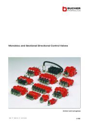
With - type . T bypass<br />
Bypass type T<br />
Thermo contact<br />
E<br />
C<br />
Bypass type S<br />
B<br />
A<br />
F (3x)<br />
#<br />
Min. space<br />
for ( filter #! 0<br />
replacement 0 1 #<br />
4” = $) 120 * +,2mm<br />
8” = ") 220 * ,,2mm<br />
4” = $) 184 * +"$ mm<br />
8” = ") 283 * ," mm<br />
Pump inlet<br />
G1 1/2 on<br />
opposite side<br />
'<br />
M ( (4x) $<br />
TYPE A B C D E F G H I J K L M O⁄<br />
<strong>LOC</strong> 004-4-D-A 267 134 135 284 73 G1 420 90 164 163 488 58 9<br />
<strong>LOC</strong>2 007-4-D-A 365 203 105 395 42 G1 510 160 215 225 558 50 9<br />
<strong>LOC</strong>2 007-4-D-B 365 203 105 395 42 G1 510 160 215 225 571 50 9<br />
<strong>LOC</strong>2 007-4-D-C 365 203 105 395 42 G1 510 160 215 225 620 50 9<br />
<strong>LOC</strong>2 007-4-D-D 365 203 105 395 42 G1 510 160 215 225 633 50 9<br />
<strong>LOC</strong>2 011-4-D-A 440 203 103 470 41 G1 510 230 252 249 582 50 9<br />
<strong>LOC</strong>2 011-4-D-B 440 203 103 470 41 G1 510 230 252 249 595 50 9<br />
<strong>LOC</strong>2 011-6-D-C 440 203 103 470 41 G1 510 230 252 249 643 50 9<br />
<strong>LOC</strong>2 011-6-D-D 440 203 103 470 41 G1 510 230 252 249 657 50 9<br />
<strong>LOC</strong>2 011-4-D-C 440 203 103 470 41 G1 510 230 252 249 644 50 9<br />
<strong>LOC</strong>2 011-4-D-D 440 203 103 470 41 G1 510 230 252 249 657 50 9<br />
<strong>LOC</strong>2 016-4-D-A 496 203 107 526 46 G1 510 230 285 272 640 50 9<br />
<strong>LOC</strong>2 016-4-D-B 496 203 107 526 46 G1 510 230 285 272 653 50 9<br />
<strong>LOC</strong>2 016-6-D-C 496 203 107 526 46 G1 510 230 285 272 665 50 9<br />
<strong>LOC</strong>2 016-6-D-D 496 203 107 526 46 G1 510 230 285 272 678 50 9<br />
<strong>LOC</strong>2 016-4-D-C 496 203 107 526 46 G1 510 230 285 272 665 50 9<br />
<strong>LOC</strong>2 016-4-D-D 496 203 107 526 46 G1 510 230 285 272 678 50 9<br />
<strong>LOC</strong>2 023-4-D-B 580 356 104 610 40 G1 610 305 322 287 668 50 14<br />
<strong>LOC</strong>2 023-6-D-C 580 356 104 610 40 G1 610 305 322 287 722 50 14<br />
<strong>LOC</strong>2 023-6-D-D 580 356 104 610 40 G1 610 305 322 287 722 50 14<br />
<strong>LOC</strong>2 023-4-D-C 580 356 104 610 40 G1 610 305 322 287 709 50 14<br />
<strong>LOC</strong>2 023-4-D-D 580 356 104 610 40 G1 610 305 322 287 722 50 14<br />
<strong>LOC</strong> 033-6-A-D 692 356 99 722 32 G1 1 ⁄4 610 406 378 318 754 70 14<br />
<strong>LOC</strong> 033-4-A-C 692 356 99 722 32 G1 1 ⁄4 610 406 378 318 727 70 14<br />
<strong>LOC</strong> 033-4-A-D 692 356 99 722 32 G1 1 ⁄4 610 406 378 318 741 70 14<br />
<strong>LOC</strong> 044-6-A-D 692 356 99 866 49 G1 1 ⁄4 610 584 450 343 779 70 14<br />
<strong>LOC</strong> 044-4-A-C 692 356 99 866 49 G1 1 ⁄4 610 584 450 343 750 70 14<br />
<strong>LOC</strong> 044-4-A-D 692 356 99 866 49 G1 1 ⁄4 610 584 450 343 762 70 14<br />
9<br />
K&<br />
G<br />
J%<br />
! "<br />
Stone # guard max. ! $ 34 mm.<br />
L/<br />
AIR<br />
H Dust guard max. 8 mm.
Key for <strong>LOC</strong> and<br />
<strong>LOC</strong>2 cooling systems<br />
All positions must be filled in when ordering.<br />
EXAMPLE:<br />
<strong>LOC</strong>2-011-6-A-C-L-50-S20-D-E0-0<br />
1 2 3 4 5 6 7 8 9 10/11 12<br />
1. TYPE OF COOLING SYSTEM = <strong>LOC</strong>/<strong>LOC</strong>2<br />
2. COOLER SIZE<br />
004, 007, 011, 016, 023, 033, 044<br />
3. NUMBER OF POLES, MOTOR<br />
4-pole = 4<br />
6-pole = 6<br />
4. VOLTAGE AND FREQUENCY<br />
Three-phase 220-240/380-420V 50 Hz * = A<br />
Three-phase 440-480V 60 Hz* = B<br />
Three-phase 220-240/380-420V 50 Hz 440/480V 60 Hz** = D<br />
Three-phase 500V 50 Hz = E<br />
Three-phase 400/690V 50 Hz 440-480 60 Hz = F<br />
Three-phase 525V 50 Hz = G<br />
Motor for special voltage (stated in plain language) = X<br />
* for <strong>LOC</strong> 033 to <strong>LOC</strong> 044<br />
** for <strong>LOC</strong> 004 – <strong>LOC</strong>2 023<br />
5. PUMP SIZE<br />
Displacement 15 cm 3 /r = A<br />
Displacement 30 cm 3 /r = B<br />
Displacement 45 cm 3 /r = C<br />
Displacement 60 cm 3 /r = D<br />
Special = X<br />
6. BYPASS VALVE, PUMP<br />
No bypass valve = 0<br />
Built-in bypass valve, 5 bar internal = L<br />
Built-in bypass valve, 10 bar internal = H<br />
Built-in bypass valve, 5 bar external = K<br />
Built-in bypass valve, 10 bar external = M<br />
7. THERMO CONTACT<br />
For temperature alarm, not for direct control of electric motor.<br />
No thermo contact = 00<br />
40 °C = 40<br />
50 °C = 50<br />
60 °C = 60<br />
70 °C = 70<br />
80 °C = 80<br />
90 °C = 90<br />
8. COOLER MATRIX<br />
Standard = 000<br />
Two-pass<br />
Built-in, pressure-controlled bypass valve, single-pass<br />
= T00<br />
2 bar = S20<br />
5 bar = S50<br />
8 bar<br />
Built-in, pressure-controlled bypass valve, two-pass*<br />
= S80<br />
2 bar = T20<br />
5 bar = T50<br />
8 bar = T80<br />
10<br />
Built-in temperature and pressure-controlled bypass valve, single-pass<br />
50 °C, 2.2 bar = S25<br />
60 °C, 2.2 bar = S26<br />
70 °C, 2.2 bar = S27<br />
90 °C, 2.2 bar<br />
Built-in temperature and pressure-controlled bypass valve, two-pass*<br />
= S29<br />
50 °C, 2.2 bar = T25<br />
60 °C, 2.2 bar = T26<br />
70 °C, 2.2 bar = T27<br />
90 °C, 2.2 bar<br />
* = Not valid for <strong>LOC</strong> 004<br />
= T29<br />
9. MATRIX GUARD<br />
No guard = 0<br />
Stone guard = S<br />
Dust guard = D<br />
Dust and stone guard = P<br />
10. FX3 FILTER UNIT (sizing, see page 6)<br />
No filter unit = 0<br />
Filter unit with 4” element HP = A<br />
Filter unit with 4” element LP = B<br />
Filter unit with 8” element HP = E<br />
Filter unit with 8” element LP = F<br />
11.PRESSURE DROP INDICATOR<br />
No pressure drop indicator = 0<br />
Visual pressure drop indicator<br />
with manual reset. = D<br />
Visual pressure drop indicator<br />
with thermo guard and manual reset.<br />
No signal below 0 o<br />
C, signal above +29 o<br />
C. = P<br />
Electric pressure drop indicator with automatic reset.<br />
Connection in accordance with DIN 43650<br />
ISO 4400 (Hirschmann) IP 65. = M<br />
Electric pressure drop indicator<br />
with 2-pole AMP contact. = U<br />
12. STANDARD/SPECIAL<br />
Standard = 0<br />
Special = Z<br />
SPARE PARTS<br />
Art. no. Description<br />
58920102 Filter element 04” HP<br />
58920103 Filter element 04” LP<br />
58920302 Filter element 08” HP<br />
58920303 Filter element 08” LP<br />
589310 O-ring for filter housing cover