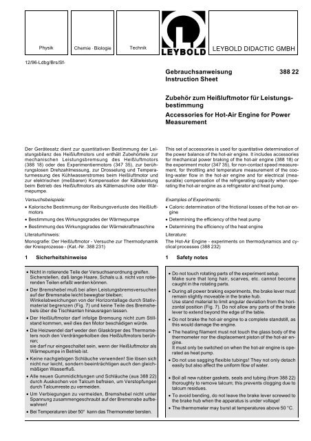
LEYBOLD DIDACTIC GMBH Gebrauchsanweisung 388 22 ...
LEYBOLD DIDACTIC GMBH Gebrauchsanweisung 388 22 ...
LEYBOLD DIDACTIC GMBH Gebrauchsanweisung 388 22 ...

You also want an ePaper? Increase the reach of your titles
YUMPU automatically turns print PDFs into web optimized ePapers that Google loves.
Physik Chemie ⋅ Biologie Technik <strong>LEYBOLD</strong> <strong>DIDACTIC</strong> <strong>GMBH</strong><br />
12/96-Ldbg/Brs/Sf-<br />
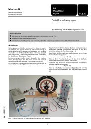
Der Gerätesatz dient zur quantitativen Bestimmung der Leistungsbilanz<br />
des Heißluftmotors und enthält Zubehörteile zur<br />
mechanischen Leistungsbremsung des Heißluftmotors<br />
(<strong>388</strong> 18) oder des Experimentiermotors (347 35), zur berührungslosen<br />
Drehzahlmessung, zur Drosselung und Temperaturmessung<br />
des Kühlwasserstromes beim Heißluftmotor und<br />
zur elektrischen (meßbaren) Kompensation der Kälteleistung<br />
beim Betrieb des Heißluftmotors als Kältemaschine oder Wärmepumpe.<br />
Versuchsbeispiele:<br />
• Kalorische Bestimmung der Reibungsverluste des Heißluftmotors<br />
• Bestimmung des Wirkungsgrades der Wärmepumpe<br />
• Bestimmung des Wirkungsgrades der Wärmekraftmaschine<br />
Literaturhinweis:<br />
Monografie: Der Heißluftmotor - Versuche zur Thermodynamik<br />
der Kreisprozesse - (Kat.-Nr. <strong>388</strong> 231)<br />
1 Sicherheitshinweise<br />
• Nicht in rotierende Teile der Versuchsanordnung greifen.<br />
Sicherstellen, daß lange Haare, Schals u.ä. nicht von rotierenden<br />
Teilen erfaßt werden können.<br />
• Der Bremshebel muß bei allen Leistungsbremsversuchen<br />
auf der Bremsnabe leicht bewegbar bleiben;<br />
Winkelabweichungen von der Horizontallage durch Stativmaterial<br />
begrenzen (Fig. 7) und keine Teile des Bremshebels<br />
über die Tischkanten hinausragen lassen.<br />
• Der Heißluftmotor darf infolge Bremsung nicht zum Stillstand<br />
kommen, weil dies den Motor beschädigen würde.<br />
• Die Heizwendel darf weder den Glaskörper des Thermometers<br />
noch den Verdrängerkolben des Heißluftmotors berühren;<br />
sie darf nur eingeschaltet sein, wenn der Heißluftmotor als<br />
Wärmepumpe in Betrieb ist.<br />
• Keine nachgiebigen Schläuche verwenden! Sie lösen sich<br />
nicht nur leicht, sondern beeinträchtigen auch den gleichmäßigen<br />
Wasserfluß.<br />
• Alle neuen Gummidichtungen und Schläuche (aus <strong>388</strong> <strong>22</strong>)<br />
durch Auskochen von Talcum befreien, um Verstopfungen<br />
durch Talcumreste zu vermeiden.<br />
• Um Verbiegungen zu vermeiden, Bremshebel nicht unter<br />
Spannung zusammengeschraubt auf der Bremsnabe aufbewahren!<br />
• Bei Temperaturen über 50° kann das Thermometer bersten.<br />
<strong>Gebrauchsanweisung</strong> <strong>388</strong> <strong>22</strong><br />
Instruction Sheet<br />
Zubehör zum Heißluftmotor für Leistungsbestimmung<br />
Accessories for Hot-Air Engine for Power<br />
Measurement<br />
This set of accessories is used for quantitative determination of<br />
the power balance of the hot-air engine. It includes accessories<br />
for mechanical power braking of the hot-air engine (<strong>388</strong> 18) or<br />
the experiment motor (347 35), for non-contact speed measurement,<br />
for throttling and temperature measurement of the cooling-water<br />
flow in the hot-air engine and for electrical (measurable)<br />
compensation of the refrigerating capacity when operating<br />
the hot-air engine as a refrigerator and heat pump.<br />
Examples of Experiments:<br />
• Caloric determination of the frictional losses of the hot-air engine<br />
• Determining the efficiency of the heat pump<br />
• Determining the efficiency of the heat engine<br />
Literature:<br />
The Hot-Air Engine - experiments on thermodynamics and cyclical<br />
processes (<strong>388</strong> 232)<br />
1 Safety notes<br />
• Do not touch rotating parts of the experiment setup.<br />
Make sure that long hair, scarves, etc. cannot become<br />
caught in the rotating parts.<br />
• During all power braking experiments, the brake lever must<br />
remain slightly moveable in the brake hub.<br />
Use stand material to limit angular deviation from the horizontal<br />
position (Fig. 7). Do not allow any parts of the brake<br />
lever to extend beyond the edge of the table.<br />
• Do not brake the hot-air engine to a complete standstill, as<br />
this would damage the engine.<br />
• The heating filament must not touch the glass body of the<br />
thermometer nor the displacement piston of the hot-air engine.<br />
It must only be switched on when the hot-air engine is operated<br />
as heat pump.<br />
• Do not use sagging flexible tubings! They not only detach<br />
easily but also affect the uniform flow of water.<br />
• Boil all new rubber gaskets, seals and tubing (from <strong>388</strong> <strong>22</strong>)<br />
thoroughly to remove talcum; this prevents clogging due to<br />
talcum residues.<br />
• To avoid bending, do not leave the brake lever screwed to<br />
the brake hub when the apparatus is under voltage!<br />
• The thermometer may burst at temperatures above 50 °C.
Fig. 1<br />
2 Lieferumfang, Beschreibung, technische Daten<br />
2.1 Zubehör zur mechanischen Leistungsbremsung des<br />
Heißluftmotors oder des Experimentiermotors (Fig. 1)<br />
� 2 Bremshebelhälften, Holz<br />
� Gewindebohrungen<br />
� Bremsbacken<br />
� 2 Rändelschrauben zum Gegeneinanderschrauben und<br />
Spannen der Bremshebelhälften<br />
� 2 Stifte mit Öse zur Befestigung eines Kraftmessers (obere<br />
Hebelhälfte) oder zum Anhängen von Massestücken (untere<br />
Hebelhälfte)<br />
� 2 Zylinderschrauben zum groben Austarieren der Bremshebelhälften<br />
(je 2 mal M6x35, M6x12, M6x5)<br />
� Bremsnabe zum Einspannen in das Futter des Experimentiermotors<br />
(347 35)<br />
Länge des Bremshebelarms (Abstand Drehpunkt - Angriffspunkt<br />
der Kraft): 0,25 m<br />
2.2 Zubehör zur berührungslosen Drehzahlmessung<br />
(Fig. 2)<br />
� Lochscheibe, Ø 160 mm<br />
für berührungslose Drehzahlmessung mittels Lichtschranke<br />
und Digitalzähler<br />
� Haltemagnet<br />
zum Anheften der Lochscheibe auf der Stirnseite der<br />
Bremsnabe des Heißluftmotors oder der in das Futter des<br />
Experimentiermotors (347 35) eingespannten Bremsnabe �<br />
2.3 Zubehör zur Kühlwassertemperatur-Messung des<br />
Heißluftmotors (Fig. 3)<br />
� Durchflußgerät<br />
� Haltemagnet zum Anheften des Durchflußgefäßes an dem<br />
Holm des Heißluftmotors<br />
� Schlauchwelle für Kühlwasserzulauf-Schlauch<br />
� Kunststoffschlauch<br />
� Schlauchwelle für Kühlwasserablauf-Schlauch<br />
� Dichtscheibe<br />
� Knebelschraube<br />
� Dichtschiebe, Øa 16 mm; Øi 9 mm; erforderlich bei Thermometer-Einsatz<br />
� Dichtscheibe, Øa 16 mm, Øi 0,5 mm; erforderlich bei Temperaturfühler-Einsatz<br />
� Schraubverschluß<br />
2<br />
Fig. 2<br />
Lochscheibe<br />
Perforated disk<br />
2 Scope of supply, description, technical data<br />
2.1 Accessories for mechanical power braking of the<br />
hot-air engine or the experiment motor (Fig. 1)<br />
� 2 brake-lever halves, wood<br />
� Threaded holes<br />
� Brake shoes<br />
� 2 knurled screws for screwing together and tensioning the<br />
brake-lever halves<br />
� 2 pins with eyes to fasten a dynamometer (upper half of<br />
lever) or to suspend weights (lower half of lever)<br />
� 2 cylinder-head screws for coarse counterbalancing of the<br />
brake-lever halves (2 each M6x35, M6x12, M6x5)<br />
� Brake hub for fitting into the chuck of the experiment motor<br />
(347 35)<br />
Length of brake lever arm (pivot to point of application of force):<br />
0.25 m<br />
2.2 Accessories for contact-free speed measurement<br />
(Fig. 2)<br />
� Perforated disk, dia. 160 mm<br />
for contact-free measurement of rotational speed using<br />
light barrier and digital counter<br />
� Holding magnet<br />
to fasten the perforated disk to the front of the brake hub in<br />
the hot-air engine or the brake hub � clamped in the chuck<br />
of the experiment motor (347 35)<br />
2.3 Accessories for measuring the cooling-water<br />
temperature of the hot-air engine (Fig. 3)<br />
� Flow-through vessel<br />
� Holding magnet to fasten the flow-through vessel to the<br />
spar of the hot-air engine<br />
� Hose nozzle for cooling-water inlet tubing<br />
� Plastic tubing<br />
� Hose nozzle for cooling-water outlet tubing<br />
� Gasket<br />
� T-screw<br />
� Gasket, 16 mm O.D., 9 mm I.D. required when using the<br />
thermometer<br />
� Gasket 16 mm, O.D., 0.5 mm I.D., required when using the<br />
temperature sensor<br />
� Screw plug
Fig. 3<br />
2.4 Zubehör zur Drosselung des Kühlwasserstromes am<br />
Wasserhahn (Fig. 4)<br />
� 3 Düsen, Øi 0,3; 0,5; 0,8 mm<br />
mit Schraubgewinde und Schlitz für Schraubendreher; zur<br />
Begrenzung des Betriebsdruckes auf Wasserschläuche<br />
und Kühlwassermantel und zur Gewährleistung eines<br />
gleichmäßigen, sich nur geringfügig ändernden Kühlwasserstromes.<br />
� Dichtscheibe<br />
� Schlauchwelle mit Innengewinde zum Einschrauben einer<br />
der Düsen �<br />
� Überwurfmutter<br />
� Schlauchschelle<br />
2.5 Zubehör zur elektrischen (meßbaren) Kompensation<br />
der Kälteleistung beim Betrieb des Heißluftmotors<br />
als Kältemaschine oder Wärmepumpe (Fig. 5)<br />
� Thermometer, fest verbunden mit �<br />
Meßbereich: 10 °C bis 45 °C<br />
1°-Teilung<br />
� Deckel mit Gewinde (Ø 18 mm) zum Einschrauben in den<br />
Zylinderkopf-Deckel des Heißluftmotors<br />
� Buchsen für die Stromversorgung der Heizwendel �<br />
� Stifte zum Aufstecken der Heizwendel �<br />
� Heizwendel zum Aufstecken auf die Stifte �<br />
max. zulässige Betriebsdaten:<br />
Spannung: 10 V<br />
Strom: 3 A<br />
3<br />
Fig. 4<br />
2.4 Accessories for throttling the cooling-water flow at<br />
the water tap (Fig. 4)<br />
� 3 nozzles, 0.3, 0.5 and 0.8 mm I.D.<br />
with screw thread and slit for screw-driver, for limiting the<br />
operating pressure on water tubings and cooling-water<br />
jacket and to ensure a uniform, only slightly varying coolingwater<br />
flow.<br />
� Gasket<br />
� Hose nozzle with internal screw thread, for screwing-in one<br />
of the nozzles �<br />
� Screw cap<br />
� Hose clip<br />
2.5 Accessories for electrical (measurable) compensation<br />
of the refrigerating capacity when operating the<br />
hot-air engine as refrigerator and heat pump (Fig. 5)<br />
� Thermometer, firmly connected with �<br />
Measuring range: 10 °C to 45 °C<br />
1° scale division<br />
� Cover with screw thread (dia. 18 mm) to be screwed into<br />
the cylinder head cover of the hot-air engine<br />
� Sockets for power supply to the heating filament �<br />
� Pins to plug on the heating filament �<br />
� Heating filament to be plugged to the pins �<br />
Max. admissible operating data:<br />
Voltage: 10 V<br />
Current: 3 A
Fig. 5<br />
3 Bedienung<br />
3.1 Montage des Bremshebels und der Bremsnabe<br />
Vor der Erstinbetriebnahme die beiden Bremshebelhälften �<br />
auf die mitgelieferte Bremsnabe � aufschieben und dort mittels<br />
der Rändelschrauben � gegeneinander festziehen. Den<br />
so vorbereiteten Bremshebel mit Hilfe zweier Unterlagen (z.B.<br />
Bücher) auf Gleichgewicht prüfen (s. Fig. 6).<br />
Grobe Abweichungen durch Einschrauben von Zylinderschrauben<br />
� an der zu leichten Stirnseite des Bremshebels näherungsweise<br />
korrigieren. Kleine Gleichgewichtsabweichungen<br />
stören nicht.<br />
Zur Leistungsbremsung von Motoren muß die sich drehende<br />
Motorwelle mit einer Nabe entsprechend � versehen sein, wie<br />
sie der Heißluftmotor besitzt. Bei Bremsversuchen des Experimentiermotors<br />
(347 35/36) ist die Bremsnabe � in das Futter<br />
einzuspannen. Bremshebelhälften � mit den Bremsbacken �<br />
auf die Nabe des betreffenden Motors aufsetzen und mit den<br />
Rändelschrauben nur so weit gegeneinanderschrauben, daß<br />
der Hebel leicht beweglich bleibt.<br />
Schwenkbarkeit des Hebels mit Hilfe von Stativmaterial begrenzen<br />
(s. Fig. 7).<br />
Kraftmesser 1 N (314 141) verwenden.<br />
Motor in Gang setzen. (s. <strong>Gebrauchsanweisung</strong> des betreffenden<br />
Motors:<br />
Experimentiermotor 347 35/36 oder Heißluftmotor <strong>388</strong> 18).<br />
An den Lastarm des Hebels (Fig. 7) 2 bis 6 Massestücke zu je<br />
50 g anhängen.<br />
Bei laufendem Motor gleichzeitig beide Flügelschrauben �<br />
vorsichtig – ohne den Motor abzuwürgen! – anziehen, bis der<br />
Kraftmesser eine geringe Kraft F anzeigt.<br />
Das ausgeübte Drehmoment ist dann:<br />
D = 0,25 m ⋅ (m ⋅ 9,81 m<br />
+ F )<br />
2<br />
s<br />
m: Masse der Massestücke<br />
F: vom Kraftmesser angezeigte Kraft<br />
und die Bremsleistung<br />
P = 2π ⋅ n ⋅ D n: Drehfrequenz (Zahl der Motor-Umdrehungen<br />
pro Sekunde)<br />
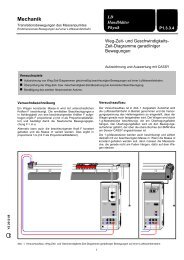
3.2 Montage der Lochscheibe (Fig. 2, Fig. 7, Fig. 8)<br />
Zur berührungslosen Drehzahlmessung des Experimentiermotors<br />
oder des Heißluftmotors wird die Lochscheibe � mit Hilfe<br />
des Haltemagneten � an der Stirnseite der Bremsnabe (beim<br />
Experimentiermotor �) angeheftet. Dies kann gefahrlos auch<br />
bei laufendem Motor geschehen.<br />
Die Lichtschranke (337 46 mittels Stativmaterial entsprechend<br />
Fig. 7 so aufbauen, daß sie die Lochscheibe umfaßt und deren<br />
Löcher den Strahlengang periodisch (pro Umdrehung 10 x) freigeben.<br />
4<br />
Fig. 6<br />
3 Operation<br />
3.1 Assembly of brake lever and brake hub<br />
Prior to initial operation fit the two brake-lever halves � to the<br />
brake hub � and tighten by means of the knurled screws �.<br />
Then check the equilibrium of this lever assembly using e.g.<br />
books as support (see fig. 6).<br />
Coarse deviations may be approximately corrected by screwing<br />
cylinder-head screws � into the end of the brake-lever arm<br />
which is too light. Small deviations in equilibrium do not affect<br />
the experiments.<br />
For power braking of motors, the rotating motor shaft must have<br />
a hub (7) like that of the hot-air engine. For braking experiments<br />
with the experiment motor (347 35/36), clamp the brake hub �<br />
into the chuck. Place the brake-lever halves � with their brake<br />
shoes onto the hub of the respective motor and tighten so far<br />
by means of the knurled screws that the lever remains<br />
slightly moveable.<br />
Use stand equipment to limit the slewing range of the lever (see<br />
fig. 7).<br />
Use dynamometer 1 N (314 141).<br />
Start the motor. (See Instruction Sheet for the respective motor:<br />
experiment motor 347 35/36 or hot air engine, <strong>388</strong> 18).<br />
Attach 2 to 6 50 g weights to the work arm of the lever (Fig. 7).<br />
Then, with the motor running, carefully and simultaneously<br />
screw down the two knurled screws � – without stalling the motor!<br />
– until the dynamometer indicates a low force F.<br />
The applied torque is then:<br />
D = 0.25 m ⋅ (m ⋅ 9.81 m<br />
+ F )<br />
2<br />
m: mass of the weights<br />
F: force indicated by the dynamometer<br />
and the brake power is:<br />
s<br />
P = 2π ⋅ n ⋅ D n: rotary frequency (number of motor<br />
revolutions per second)<br />
3.2 Assembly of the perforated disk (see Figs. 2, 7, and 8)<br />
For contact-free speed measurement of experiment motor or<br />
hot-air engine fasten the perforated disk � to the front of the<br />
hub (with experiment motor �) using the holding magnet �.<br />
This can also be done without risk while the motor is running.<br />
Set up the light barrier (337 46) using stand equipment according<br />
to Fig. 7 with the arms on either side of the perforated disk,<br />
so that the holes of the disk allow the light rays to pass<br />
periodically (10 times per revolution).
Betriebsart des Digitalzählers: Frequenzmessung<br />
Zwischen der angezeigten Impulsfrequenz f und der Motor-<br />
Dreh-Frequenz n gilt die Beziehung:<br />
n = 0,1 ⋅ f<br />
3.3 Montage des Durchflußgerätes (Fig. 3)<br />
Zur Erstinbetriebnahme Durchflußgefäß � mit dem Magneten<br />
� am vertikalen Holm des Heißluftmotors anheften.<br />
Schlauchverbindung am oberen Anschluß des Kühlwassermantels<br />
des Heißluftmotors lösen und mit dem oberen Anschluß<br />
� des Durchflußgefäßes � verbinden. Den unteren Anschluß<br />
� des Durchflußgefäßes durch den beigefügten<br />
Schlauch � mit dem freigewordenen oberen Anschluß des<br />
Kühlwassermantels verbinden.<br />
Für genaue Messungen mit dem Durchflußgefäß Thermometer<br />
(382 36) entsprechend Fig. 3 in das Durchflußgefäß einsetzen<br />
und verschrauben.<br />
Für Demonstrationsmessungen mit dem Temperaturfühler<br />
(666 193) ist anstelle der Dichtscheibe � die Dichtscheibe �<br />
einzusetzen.<br />
3.4 Montage der Drossel (Fig. 4)<br />
Eine der drei Düsen � auswählen (siehe Versuchsbeschreibung)<br />
und mit einem Schraubendreher (Klingenbreite 5 mm) in<br />
die Schlauchwelle � einschrauben, Schlauch (z.B. 307 68)<br />
durch Überwurfmutter � stecken, auf Schlauchwelle � schieben<br />
und mit Schlauchschelle � befestigen. Dichtscheibe �<br />
einlegen und mit Hilfe der Überwurfmutter � dichte Verbindung<br />
mit dem Wasserhahn herstellen. Das freie Schlauchende auf die<br />
Schlauchwelle für den Kühlwassereingang des Heißluftmotors<br />
schieben.<br />
3.5 Montage des Thermometers mit Heizung (Fig. 5)<br />
Thermometerverschraubung des Zylinderkopfdeckels vollständig<br />
lösen. Thermometer (<strong>388</strong> 19) ausbauen.<br />
Heizwendel � des Thermometers mit Heizung � von dessen<br />
Kontaktstiften � abziehen.<br />
Thermometer mit Heizung in den Zylinderkopfdeckel des<br />
Heißluftmotors einführen und dicht verschrauben.<br />
Heizwendel � wieder auf die Kontaktstifte � aufschieben.<br />
Darauf achten, daß die Heizwendel nicht den Glaskörper des<br />
Thermometers berührt!<br />
Zylinderkopfdeckel vorsichtig auf den Zylinder des Heißluftmotors<br />
aufsetzen und gleichmäßig festziehen.<br />
Achtung! Die Heizwendel darf den Verdrängerkolben bei keiner<br />
Kolbenstellung berühren!<br />
3.6 Zusätzlich erforderliche Geräte<br />
1 Heißluftmotor<br />
druckfeste Schläuche zur Kühlwasserversorgung<br />
Werkzeug, z.B.<br />
<strong>388</strong> 18<br />
1 Schraubendreher, Klingenbreite ca. 5 mm<br />
Stativmaterial (Fig. 7/Fig. 8)<br />
1 Stativfuß, Seitenlänge 20 cm 300 02<br />
1 Stativstange, 25 cm 300 41<br />
1 Stativstange,47 cm 300 42<br />
1 Stativstange, um 90° abgewinkelt 300 51<br />
3 Leybold-Muffen 301 01<br />
zur Bremskraftmessung (Fig. 7)<br />
5 Massestücke, 50 g aus 342 61<br />
1 Kraftmesser, 1 N 314 141<br />
5<br />
Operating mode of digital counter: measurement of frequency.<br />
The relationship between indicated pulse frequency f and rotational<br />
speed of motor n is:<br />
n = 0.1 ⋅ f<br />
3.3 Assembly of the flow-through vessel (Fig. 3)<br />
For initial operation fasten the flow-through vessel � to the vertical<br />
spar of the hot-air engine using the holding magnet �.<br />
Detach the tube connection on the upper connection of the cooling-water<br />
jacket of the hot-air engine and fit it to the upper connection<br />
� of the flow-through vessel �. Then connect the<br />
lower connection � of the flow-through vessel to the now free<br />
upper connection of the cooling-water jacket using the tubing �<br />
which is included in the standard equipment.<br />
For precise measurements with the flow-through vessel, insert<br />
the thermometer (382 36) according to Fig. 3 and secure by<br />
screw.<br />
For demonstration measurements using the temperature sensor<br />
(666 193), insert the gasket � instead of gasket �.<br />
3.4 Assembly of the throttle (Fig. 4)<br />
Select one of the three nozzles � (see description of experiment)<br />
and screw it into the hose nozzle � using a screw-driver<br />
(blade width 5 mm). Pass tubing (e.g. 307 68) through screw<br />
cap � push it on hose nozzle � and secure by hose clip �.<br />
Insert gasket � and make tight connection to the tap by means<br />
of the screw cap �. Push the free tubing end onto the hose<br />
nozzle for the cooling-water inlet of the hot-air engine.<br />
3.5 Assembly of the thermometer with heater (Fig. 5)<br />
Detach the thermometer screw connection of the cylinder-head<br />
cover completely. Remove the thermometer (<strong>388</strong> 19).<br />
Pull off the heating filament � of the thermometer with heater<br />
� from the contact pins �.<br />
Introduce the thermometer with heater into the cylinder-head<br />
cover of the hot-air engine and secure firmly.<br />
Push the heating filament � again onto the contact pins �.<br />
Make sure that the heating filament does not touch the glass<br />
body of the thermometer.<br />
Carefully place the cylinder cover onto the cylinder of the hot-air<br />
engine and tighten firmly.<br />
Important: the heating filament must never touch the displacing<br />
piston at any point in the piston’s cycle!<br />
3.6 Additionally required equipment:<br />
1 Hot-air engine<br />
Pressure-proof tubings for cooling-water supply<br />
Tools, e.g.<br />
<strong>388</strong> 18<br />
1 Screw-driver, blade width approx. 5 mm<br />
Stand equipment (Figs. 7 and 8)<br />
1 Stand base, length of sides 20 cm 300 02<br />
1 Stand rod, 25 cm 300 41<br />
1 Stand rod, 47 cm 300 42<br />
1 Stand rod, right angled 300 51<br />
3 Leybold multiclamps 301 01<br />
For measurement of braking force (Fig. 7)<br />
5 Weights, 50 g from 342 61<br />
1 Dynamometer, 1 N 314 141
zur Energieversorgung des Heißluftmotors (Fig. 7)<br />
1 Spannungsquelle bis 14 V, 3 A, z.B.<br />
1 U-Kern mit Joch 562 11<br />
1 Spannungsvorrichtung 562 12<br />
1 Netzspule mit 500 Windungen (bei 230 V�) 562 21<br />
1 Kleinspannungsspule, 50 Windungen 562 18<br />
zur Drehzahlmessung (Fig. 7/Fig. 8)<br />
1 Gabel-Lichtschranke 337 46<br />
1 Verbindungskabel, 6-polig, 1,5 m 501 16<br />
1 LH Digitalzähler 575 40<br />
für den mechanischen Antrieb (Fig. 8):<br />
1 Experimentiermotor 347 35<br />
1 Steuergerät 347 36<br />
zur Temperaturmessung des Kühlwassers (Fig. 7/Fig. 8):<br />
1 Thermometer, - 10 °C bis + 40 °C 382 36<br />
oder<br />
1 Temperaturfühler 666 193<br />
mit Digitalem Temperaturmeßgerät 666 190<br />
zur kontrollierten Zylinderkopf-Beheizung (Fig. 8):<br />
1 Spannungsquelle, einstellbar bis 12 V, 3 A, z.B.<br />
1 Kleinspannungsstelltrafo S 521 35<br />
1 Voltmeter bis 12 V� z.B. 531 51<br />
1 Amperemeter bis 3 A� z.B. 531 100<br />
zur Messung des Kühlwasserdurchsatzes (Fig. 8):<br />
1 Tischstoppuhr 313 05<br />
oder<br />
1 Handstoppuhr 313 07<br />
1 Kunststoffbecher, 1000 ml 590 06<br />
4 Versuchsaufbauten<br />
Fig. 7<br />
Bestimmung des Wirkungsgrades des Heißluftmotors als<br />
Kraftmaschine<br />
Determining the efficiency of the hot-air engine operating as a power<br />
engine<br />
For energy supply to hot-air engine (Fig. 7)<br />
1 Voltage source up to 14 V, 3 A, e.g.<br />
1 U-core with yoke 562 11<br />
1 Clamping device 562 12<br />
1 Mains coil with 500 turns (at 230 V AC) 562 21<br />
1 Extra-low voltage coil 50 turns 562 18<br />
For speed measurement (Figs. 7 and 8)<br />
1 Forked light barrier 337 46<br />
1 Multi-core cable, 6-pole, 1.5 m 501 16<br />
1 Leybold digital counter 575 40<br />
For mechanical drive (Fig. 8):<br />
1 Experiment motor 347 35<br />
1 Control unit 347 36<br />
For temperature measurement (Figs 7 and 8):<br />
1<br />
or<br />
Thermometer, - 10 °C to + 40 °C 382 36<br />
1 Temperature sensor 666 193<br />
with Digital thermometer 666 190<br />
For controlled cylinder-head heating (Fig. 8)<br />
1 Voltage source, adjustable up to 12 V, 3 A, e.g.<br />
1 Extra-low voltage transformer S 521 35<br />
1 Voltmeter up to 12 V AC e.g. 531 51<br />
1 Ammeter, up to 3 A AC e.g. 531 100<br />
For measurement of cooling-water flow (Fig. 8):<br />
1<br />
or<br />
Stop-clock 313 05<br />
1 Stop-clock 313 07<br />
1 Plastic beaker, 1000 ml 590 06<br />
4 Experiment setups<br />
Fig. 8<br />
Bestimmung des Wirkungsgrades des Heißluftmotors als<br />
Wärmepumpe (Kältemaschine)<br />
Determining the efficiency of the hot-air engine operating as heat<br />
pump (refrigerator)<br />
<strong>LEYBOLD</strong> <strong>DIDACTIC</strong> <strong>GMBH</strong> ⋅ Leyboldstrasse 1 ⋅ D-50354 Hürth ⋅ Phone (0<strong>22</strong>33) 604-0 ⋅ Telefax (0<strong>22</strong>33) 604-<strong>22</strong>2 ⋅ Telex 17 <strong>22</strong>3 332 LHPCGN D<br />
© by Leybold Didactic GmbH, Printed in the Federal Republic of Germany<br />
Technical alterations reserved
![[667 359] Labor-Refraktometer - LD DIDACTIC](https://img.yumpu.com/24788329/1/184x260/667-359-labor-refraktometer-ld-didactic.jpg?quality=85)