LEYBOLD DIDACTIC GMBH Gebrauchsanweisung 579 18 ...
LEYBOLD DIDACTIC GMBH Gebrauchsanweisung 579 18 ...
LEYBOLD DIDACTIC GMBH Gebrauchsanweisung 579 18 ...

Sie wollen auch ein ePaper? Erhöhen Sie die Reichweite Ihrer Titel.
YUMPU macht aus Druck-PDFs automatisch weboptimierte ePaper, die Google liebt.
Physik Chemie ⋅ Biologie Technik <strong>LEYBOLD</strong> <strong>DIDACTIC</strong> <strong>GMBH</strong><br />
10/96-Brs/Ha/Wi-<br />
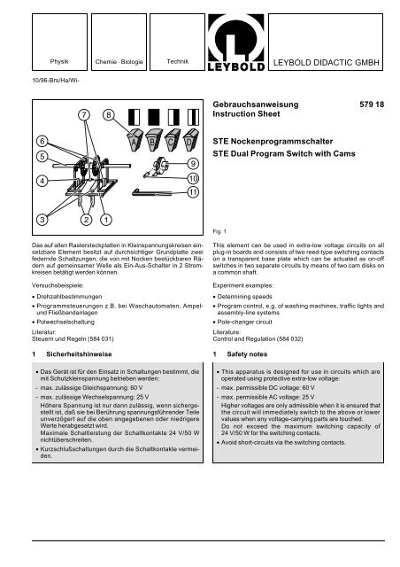
<strong>Gebrauchsanweisung</strong> <strong>579</strong> <strong>18</strong><br />
Instruction Sheet<br />
STE Nockenprogrammschalter<br />
STE Dual Program Switch with Cams<br />
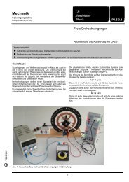
Fig. 1<br />
Das auf allen Rastersteckplatten in Kleinspannungskreisen einsetzbare<br />
Element besitzt auf durchsichtiger Grundplatte zwei<br />
federnde Schaltzungen, die von mit Nocken bestückbaren Rädern<br />
auf gemeinsamer Welle als Ein-Aus-Schalter in 2 Stromkreisen<br />
betätigt werden können.<br />
Versuchsbeispiele:<br />
• Drehzahlbestimmungen<br />
• Programmsteuerungen z.B. bei Waschautomaten, Ampelund<br />
Fließbandanlagen<br />
• Polwechselschaltung<br />
Literatur:<br />
Steuern und Regeln (584 031)<br />
1 Sicherheitshinweise<br />
• Das Gerät ist für den Einsatz in Schaltungen bestimmt, die<br />
mit Schutzkleinspannung betrieben werden:<br />
- max. zulässige Gleichspannung: 60 V<br />
- max. zulässige Wechselspannung: 25 V<br />
Höhere Spannung ist nur dann zulässig, wenn sichergestellt<br />
ist, daß sie bei Berührung spannungsführender Teile<br />
unverzögert auf die oben angegebenen oder niedrigere<br />
Werte herabgesetzt wird.<br />
Maximale Schaltleistung der Schaltkontakte 24 V/50 W<br />
nichtüberschreiten.<br />
• Kurzschlußschaltungen durch die Schaltkontakte vermeiden.<br />
This element can be used in extra-low voltage circuits on all<br />
plug-in boards and consists of two reed-type switching contacts<br />
on a transparent base plate which can be actuated as on-off<br />
switches in two separate circuits by means of two cam disks on<br />
a common shaft.<br />
Experiment examples:<br />
• Determining speeds<br />
• Program control, e.g. of washing machines, traffic lights and<br />
assembly-line systems<br />
• Pole-changer circuit<br />
Literature:<br />
Control and Regulation (584 032)<br />
1 Safety notes<br />
• This apparatus is designed for use in circuits which are<br />
operated using protective extra-low voltage:<br />
- max. permissible DC voltage: 60 V<br />
- max. permissible AC voltage: 25 V<br />
Higher voltages are only admissible when it is ensured that<br />
the circuit will immediately switch to the above or lower<br />
values when any voltage-carrying parts are touched.<br />
Do not exceed the maximum switching capacity of<br />
24 V/50 W for the switching contacts.<br />
• Avoid short-circuits via the switching contacts.
2 Beschreibung, technische Daten<br />
1 Grundplatte, 60 mm x 57 mm x 2,5 mm, durchsichtig<br />
2 Steckerstifte, 4 mm, Abstand 19 mm<br />
Abstand zum Stiftpaar 7: 50 mm<br />
3 Schaltzungen, rückfedernd mit Wolfram-Kontakten<br />
max. zulässige Werte für<br />
Schaltspannung: 24 V<br />
Schaltleistung: 50 W<br />
4 Lagerbock<br />
5 Anschlußwelle, 4 mm Ø<br />
6 Nockenräder mit je 12 Nocken-Nuten im 30°-Abstand<br />
7 Steckerstifte, 4 mm Ø, Abstand 19 mm<br />
8 Schaltnocken (Schaltfunktions-Angaben bei Drehung im<br />
Uhrzeigersinn)<br />
6x Typ A, mit 15° "offen", 15° "geschlossen"<br />
(Typ C, Rückseite)<br />
<strong>18</strong> x Typ B, mit 30° "geschlossen"<br />
6x Typ C, mit 15° "geschlossen, 15° "offen"<br />
(Typ A, Rückseite)<br />
6x Typ D, mit 12,5° "offen", 5° "geschlossen"<br />
9 Kupplung, mit Riemenscheibe (Ø 27 mm)<br />
mit Inbusschrauben A fixierbar auf Anschlußwelle 5 zur<br />
Verbindung von 2 STE-Nockenprogrammschaltern oder<br />
auf der Abtriebswelle des STE-Motors 12 V(, 4 W, mit Getriebe<br />
(<strong>579</strong> 36)<br />
A Inbusschrauben zum Befestigen der Kupplung 9 an der<br />
Anschlußwelle 5 oder an der Abtriebswelle des Motors<br />
(<strong>579</strong> 36)<br />
B Inbusschlüssel<br />
3 Bedienung<br />
Mit einem Nockenprogrammschalter können zwei Stromkreise<br />
ein- und ausgeschaltet werden.<br />
Entsprechend der Anzahl der Stromkreise Zahl der Nockenprogrammschalter<br />
wählen und durch die Kupplung 9 die Anschlußwellen<br />
5 miteinander verbinden. Elemente auf eine Rastersteckplatte<br />
(576 74, 576 75 oder 580 10) aufstecken. Inbusschrauben<br />
A mit Inbusschlüssel B festschrauben. Die einzelnen<br />
Schaltungen in die nach Programm zu betreibenden<br />
Stromkreise einfügen (s. Fig. 2).<br />
Die Programmierung erfolgt durch Aufstecken der Nocken auf<br />
die Nockenräder.<br />
Die Nocken vom Typ A, B oder C übernehmen jeweils zwei<br />
Schaltentscheidungen pro 30°. Mit diesen Nocken können beliebig<br />
vorgegebene Schaltfolgen mit 24 Schaltentscheidungen<br />
(Kontakt offen "0", Kontakt leitend "1") realisiert werden. Die<br />
Nocken vom Typ D erlauben Kurz-Einschaltungen.<br />
Antriebsarten:<br />
entweder<br />
Handantrieb durch Drehen an einem Nockenrad 6 oder an der<br />
Riemenschiebe der Anschlußwelle<br />
oder<br />
Elektromagnetischer Antrieb mit einstellbarer Frequenz mittels<br />
STE Motor 12 V/4 W mit Getriebe (<strong>579</strong> 36).<br />
2 Description, technical data<br />
1 Base plate, 60 mm x 57 mm x 2.5 mm, transparent<br />
2 Plug pins, 4 mm, spacing 19 mm<br />
distance from pin pair 7: 50 mm<br />
3 Reed-type switching contacts, elastic recovery, with tungsten<br />
contact tips<br />
Max. permissible values for<br />
Switching voltage: 24 V<br />
Switching power: 50 W<br />
4 Bearing<br />
5 Connection shaft, dia. 4 mm<br />
6 Cam disks with 12 cam grooves each in 30° spacing<br />
7 Plug pins, 4 mm dia., spacing 19 mm<br />
8 Switching cams (to execute switching function when turning<br />
in clockwise direction)<br />
6x type A, with 15° "open", 15° "closed"<br />
(type C, rear)<br />
<strong>18</strong> x type B, with 30° "closed"<br />
6x type C, with 15° "closed, 15° "open"<br />
(type A, rear)<br />
6x type D, with 12,5° "open", 5° "closed"<br />
9 Coupling, with belt pulley (dia. 27 mm)<br />
for mounting on connection shaft 5 with Allan screws A,<br />
for connecting 2 STE-dual program switches with cams to<br />
drive shaft of the STE-motor 12 V DC, 4 W, with gear<br />
(<strong>579</strong> 36)<br />
A Allan screws for mounting coupling 9 to connection shaft<br />
5 or to the drive shaft of motor (<strong>579</strong> 36)<br />
B Allan wrench<br />
3 Operation<br />
One dual program switch can be used to switch two circuits on<br />
and off.<br />
Determine the number of dual program switches needed according<br />
to the number of circuits and connect the drive shafts5<br />
together using the coupling 9. Mount the elements on a plug-in<br />
board (576 74, 576 75 or 580 10). Tighten Allan screws A with<br />
Allan wrench B. Integrate the individual arrangements in the<br />
circuits to be program-controlled (see Fig. 2).<br />
The circuits are programmed by attaching cams to the disks.<br />
Cams of types A, B or C each execute two switching decisions<br />
per 30°. Using these cams allows you to realize any switching<br />
sequences with 24 switching decisions (contact open "0", contact<br />
conductive "1"). Type-D cams enable brief on-states.<br />
Drive types:<br />
either<br />
manually driven by turning a cam disk 6 or the belt pulley of the<br />
drive shaft<br />
or<br />
electromagnetic drive with adjustable frequency using the STE<br />
motor 12 V/4 W with gear (<strong>579</strong> 36).<br />
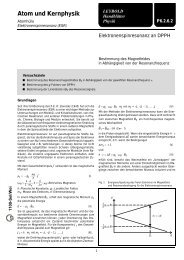
Fig. 2<br />
Schaltung zur automatischen Steuerung einer Verkehrsampel.<br />
Glühlampe 1: grün, 2: gelb, 3: rot<br />
Circuit for automatic control of a traffic light<br />
Lamp: 1 green, 2: yellow, 3: red<br />
<strong>LEYBOLD</strong> <strong>DIDACTIC</strong> <strong>GMBH</strong> ⋅ Leyboldstrasse 1 ⋅ D-50354 Hürth ⋅ Phone (02233) 604-0 ⋅ Telefax (02233) 604-222 ⋅ Telex 17 223 332 LHPCGN D<br />
© by Leybold Didactic GmbH, Printed in the Federal Republic of Germany<br />
Technical alterations reserved
![[667 359] Labor-Refraktometer - LD DIDACTIC](https://img.yumpu.com/24788329/1/184x260/667-359-labor-refraktometer-ld-didactic.jpg?quality=85)