IR-2 - Meritor WABCO
IR-2 - Meritor WABCO
IR-2 - Meritor WABCO

You also want an ePaper? Increase the reach of your titles
YUMPU automatically turns print PDFs into web optimized ePapers that Google loves.
TP-0357<br />
Issued 09-03<br />
Technical Bulletin<br />
TP-0357 Issued 1 Technical 09-03 Bulletin<br />
<strong>Meritor</strong> <strong>WABCO</strong> Inversion<br />
Relay Valve (<strong>IR</strong>-2)<br />
Hazard Alert Messages<br />
Read and observe all Warning and Caution hazard alert messages in<br />
this publication. They provide information that can help prevent<br />
serious personal injury, damage to components, or both.<br />
WARNING<br />
To prevent serious eye injury, always wear safe eye protection<br />
when you perform vehicle maintenance or service.<br />
Park the vehicle on a level surface. Block the wheels to<br />
prevent the vehicle from moving. Support the vehicle with<br />
safety stands. Do not work under a vehicle supported only by<br />
jacks. Jacks can slip and fall over. Serious personal injury and<br />
damage to components can result.<br />
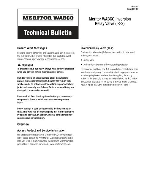
Inversion Relay Valve (<strong>IR</strong>-2)<br />
The inversion relay valve (<strong>IR</strong>-2) combines the functions of two air<br />
brake system valves:<br />
A relay valve<br />
An inversion valve with anti-compounding protection<br />
Under normal conditions, the <strong>IR</strong>-2 responds to a control signal from<br />
a dash-mounted parking brake control valve to supply or exhaust air<br />
from the spring brake chambers, thereby applying the spring<br />
brakes. In the event of a primary air system failure, the <strong>IR</strong>-2 makes<br />
a modulated application of the spring brakes by means of the foot<br />
valve. A typical <strong>IR</strong>-2 valve installation is shown in Figure 1.<br />
Release all air from the air systems before you remove any<br />
components. Pressurized air can cause serious personal<br />
injury.<br />
Do not attempt to open or disassemble the inversion relay<br />
valve. This valve has an internal spring that may be damaged<br />
by opening the valve. In addition, internal spring forces may<br />
cause serious personal injury.<br />
Overview<br />
Access Product and Service Information<br />
For additional information about <strong>Meritor</strong> <strong>WABCO</strong>’s inversion relay<br />
valve, please contact the Arvin<strong>Meritor</strong> Customer Service Center at<br />
800-535-5560. Literature covering the complete <strong>Meritor</strong> <strong>WABCO</strong><br />
product line is posted on our website, www.meritorwabco.com.
Figure 1<br />
A<strong>IR</strong><br />
FROM<br />
INLET<br />
FILTER<br />
SECONDARY<br />
RESERVO<strong>IR</strong><br />
PURGE<br />
TANK<br />
ACC<br />
WET<br />
TANK<br />
PRIMARY<br />
RESERVO<strong>IR</strong><br />
SUPPLY LINE<br />
PARKING BRAKE<br />
CONTROL LINE<br />
4003018b<br />
Figure 1<br />
Installation<br />
Figure 2<br />
Guidelines<br />
NOTE: If you are installing the inversion relay valve on an existing<br />
installation, you must first remove the old valve. Refer to the valve<br />
replacement procedure in this bulletin for instructions.<br />
1. Mount the valve.<br />
Refer to the vehicle manufacturer’s specifications for<br />
specific mounting requirements.<br />
Select a flat mounting surface. The mounting surface must<br />
be within 0.010-inch (0.25 mm) of flat.<br />
Figure 2<br />
EXHAUST<br />
4003006a<br />
For best timing results, mount the valve near the spring<br />
brakes it will serve.<br />
Mount the valve with the exhaust port facing down within<br />
30° of vertical.<br />
Use 8 mm mounting hardware to attach the valve to the<br />
mounting surface. Tighten to 15 ± 2 lb-ft (20 ± 3 Nm).<br />
Figure 2. @<br />
TP-0357<br />
Issued 09-03 (16579/24240)<br />
Page 2 Copyright Arvin<strong>Meritor</strong>, Inc., 2003 Printed in the USA
2. Connect the air lines as indicated in Table A. Valve ports are<br />
identified in Figure 3.<br />
Figure 3<br />
Make sure all unused supply and delivery ports are<br />
plugged.<br />
Look at the air line installation to make sure all air lines are<br />
correctly installed and that all connections are secure.<br />
Figure 3<br />
Table A: <strong>IR</strong>-2 Valve Port Identification<br />
<strong>IR</strong>-2 Valve Port Assignments<br />
Port Function Typical Line Size<br />
11<br />
12<br />
Reservoir ports<br />
NOTE: If the system includes<br />
a line with blended air from<br />
both tanks through a double<br />
check valve, only one supply<br />
line is connected to the valve.<br />
Plug the remaining port.<br />
1/2" O.D. Tube<br />
21<br />
22<br />
23<br />
24<br />
PORT 22<br />
PORT 42<br />
PORT 11<br />
PORT 21<br />
PORT 23<br />
EXHAUST<br />
Delivery ports to spring brake<br />
chambers. If the vehicle has<br />
only two spring brakes, plug<br />
the remaining two ports.<br />
41 Control port to primary<br />
brake circuit<br />
42 Control port to secondary<br />
brake circuit<br />
43 Control port to park brake<br />
valve<br />
PORT 24<br />
PORT 43<br />
PORT 41<br />
PORT 12<br />
3/8" I.D. Hose<br />
4003007a<br />
3/8" O.D. Tube or<br />
Push-to-Connect<br />
3/8" O.D. Tube or<br />
Push-to-Connect<br />
3/8" O.D. Tube or<br />
Push-to-Connect<br />
Troubleshooting<br />
Function Tests<br />
Non-Failure Mode<br />
When the vehicle’s primary air system is functioning correctly, the<br />
<strong>IR</strong>-2 valve passes reservoir air to the spring brake chambers as<br />
directed by the park brake valve. To test this operation:<br />
1. Park the vehicle and apply the parking brakes. Place blocks<br />
under the tires to prevent the vehicle from moving.<br />
2. Follow standard shop procedures to install a test gauge in the<br />
delivery line of the valve or at the spring brake chamber.<br />
3. Fully charge the air brake system to 105-130 psi<br />
(724-896 kPa).<br />
4. Release the parking brakes by pushing in the dash-mounted<br />
park brake knob.<br />
5. Check the pressure reading. The test gauge pressure reading<br />
should be 90-105 psi (621-724 kPa).<br />
6. Apply the parking brakes by pulling out the dash-mounted park<br />
brake knob. The <strong>IR</strong>-2 will exhaust all air in the spring brake<br />
chambers, applying the spring brakes.<br />
If the <strong>IR</strong>-2 valve does not function as described, check the<br />
installation. Make sure all air lines are correctly routed. Check<br />
the connections for leaks. Make the necessary repairs and<br />
retest. If the problem persists, it may be necessary to replace<br />
the valve. If you have any questions or need additional<br />
assistance, contact the Arvin<strong>Meritor</strong> Customer Service Center<br />
at 800-535-5560.<br />
Anti-Compounding<br />
The anti-compounding feature occurs if the service brakes are<br />
applied while the spring brakes are already applied. If this occurs,<br />
the valve will deliver air to the spring brake chambers to release the<br />
spring brakes. To test this function:<br />
1. Park the vehicle. Do not apply the parking brakes. Place blocks<br />
under the tires to prevent the vehicle from moving.<br />
2. Follow standard shop procedures to install a test gauge in the<br />
delivery line of the valve or at the spring brake chamber.<br />
3. Fully charge the air brake system to 105-130 psi<br />
(724-896 kPa).<br />
4. Apply the parking brakes by pulling out the dash-mounted park<br />
brake knob. The <strong>IR</strong>-2 will exhaust all air in the spring brake<br />
chambers, applying the spring brakes.<br />
TP-0357<br />
(16579/24240) Issued 09-03<br />
Printed in the USA Copyright Arvin<strong>Meritor</strong>, Inc., 2003 Page 3
5. Make a service brake application by stepping on the foot<br />
valve. This will send reservoir service brake air to the spring<br />
brakes.<br />
6. Check the pressure gauge to ensure reservoir pressure<br />
is delivered to the spring brakes, thus indicating the<br />
anti-compounding feature is functional.<br />
If the <strong>IR</strong>-2 valve does not function as described, check the<br />
installation. Make sure all air lines are correctly routed.<br />
Check the connections for leaks. Make the necessary<br />
repairs and retest. If the problem persists, it may be<br />
necessary to replace the valve. If you have any questions or<br />
need additional assistance, contact the Arvin<strong>Meritor</strong><br />
Customer Service Center at 800-535-5560.<br />
Failed Primary System Function<br />
If there is a loss of the primary system air, the valve will respond<br />
to the remaining signal from the secondary brake system. When<br />
secondary pressure increases to 10 psi (69 kPa), the valve will<br />
begin to exhaust air from the spring brake chambers. The spring<br />
brake chambers will be exhausted, fully applying the brakes,<br />
before the secondary service pressure exceeds 75 psi (517 kPa).<br />
To test this function:<br />
1. Place blocks under the tires to prevent the vehicle from<br />
moving.<br />
2. Follow standard shop procedures to install a test gauge in<br />
the delivery line of the valve or at the spring brake chamber.<br />
3. Fully charge the air brake system to 105-130 psi<br />
(724-896 kPa).<br />
4. Drain the air from the primary reservoir.<br />
5. Make a service brake application by stepping on the foot<br />
valve. This exhausts air from the spring brakes.<br />
6. Check the pressure reading. The test gauge should read<br />
0 when the secondary service pressure exceeds 70 psi<br />
(483 kPa).<br />
If the <strong>IR</strong>-2 valve does not function as described, check the<br />
installation. Make sure all air lines are correctly routed.<br />
Check the connections for leaks. Make the necessary<br />
repairs and retest. If the problem persists, it may be<br />
necessary to replace the valve. If you have any questions or<br />
need additional assistance, contact the Arvin<strong>Meritor</strong><br />
Customer Service Center at 800-535-5560.<br />
Air Leakage<br />
Replace the <strong>IR</strong>-2 valve if leakage exceeds 175 sccm.<br />
NOTE: If accurate measurement equipment is not available,<br />
replace any valve that has a clearly audible air leak.<br />
Leak Test<br />
Perform a leak test to check for air leakage at the air line<br />
connections.<br />
1. Place blocks under the tires to prevent the vehicle from<br />
moving.<br />
2. Drain air from all system tanks.<br />
3. Close the reservoir drain cocks.<br />
4. Start the vehicle. Allow air system pressure to build to<br />
cut-out pressure while the engine idles.<br />
If the vehicle is equipped with an air dryer: There<br />
will be a purge or strong blast of air from the air dryer,<br />
followed by a mild flow which will last 10-25 seconds<br />
when cut-out pressure is reached.<br />
5. Apply a soap solution to each connection that contains<br />
pressurized air. Check the connections for soap solution<br />
bubbles.<br />
No soap bubbles: Connections are sealed.<br />
Soap bubbles: Connections are not sealed.<br />
Connection Seal Repair<br />
To repair connection seals:<br />
1. Drain all reservoirs.<br />
2. Remove the leaking connection.<br />
3. Inspect the connections and ports for damaged threads or<br />
cracks. Replace if necessary.<br />
4. Apply pipe sealant to the pipe thread connection.<br />
NOTE: Repeat the leak test until all connections are sealed.<br />
Ensure that tubes are cut squarely to avoid damage to seals<br />
during insertion into push-to-connect fittings.<br />
TP-0357<br />
Issued 09-03 (16579/24240)<br />
Page 4 Copyright Arvin<strong>Meritor</strong>, Inc., 2003 Printed in the USA
Procedures<br />
Valve Replacement<br />
1. Place blocks under the tires to prevent the vehicle from<br />
moving<br />
2. Identify, mark and disconnect all air lines from the valve.<br />
3. Remove the mounting hardware that holds the valve to the<br />
vehicle.<br />
4. Remove the old valve from the vehicle.<br />
5. Install the replacement <strong>IR</strong>-2 valve. Refer to the installation<br />
guidelines in this bulletin for installation instructions.<br />
6. Reconnect the pneumatic lines. Refer to Table A for more<br />
information.<br />
NOTE: All lines must be reinstalled in the same location<br />
they were in before they were removed. Refer to the vehicle<br />
manufacturer’s service manual for complete instructions.<br />
7. Apply 105-130 psi (724-896 kPa) minimum air system<br />
pressure. Test the installation, following the function tests<br />
procedures in this bulletin.<br />
TP-0357<br />
(16579/24240) Issued 09-03<br />
Printed in the USA Copyright Arvin<strong>Meritor</strong>, Inc., 2003 Page 5
<strong>Meritor</strong> <strong>WABCO</strong><br />
Vehicle Control Systems<br />
3331 West Big Beaver Road, Suite 300<br />
Troy, MI 48084 USA<br />
800-535-5560<br />
meritorwabco.com<br />
Information contained in this publication was in effect at the time the publication was approved for printing and is subject to<br />
change without notice or liability. <strong>Meritor</strong> <strong>WABCO</strong> reserves the right to revise the information presented or discontinue the<br />
production of parts described at any time.<br />
Copyright 2003<br />
TP-0357<br />
Arvin<strong>Meritor</strong>, Inc. Issued 09-03<br />
All Rights Reserved<br />
Printed in the USA<br />
16579/24240