Anti-Lock Braking Systems (ABS) for Trucks ... - Meritor WABCO
Anti-Lock Braking Systems (ABS) for Trucks ... - Meritor WABCO
Anti-Lock Braking Systems (ABS) for Trucks ... - Meritor WABCO

You also want an ePaper? Increase the reach of your titles
YUMPU automatically turns print PDFs into web optimized ePapers that Google loves.
<strong>Anti</strong>-<strong>Lock</strong> <strong>Braking</strong> <strong>Systems</strong>(<strong>ABS</strong>) <strong>for</strong> <strong>Trucks</strong>, Tractorsand BusesMaintenance Manual No. 28Revised 4-98• For C Version ECUs
Service NotesThis Maintenance Manual describes the correct service, replacement installation and operation procedures<strong>for</strong> <strong>Meritor</strong> <strong>WABCO</strong> <strong>Anti</strong>-<strong>Lock</strong> <strong>Braking</strong> <strong>Systems</strong> <strong>for</strong> <strong>Trucks</strong>, Tractors and Buses. The in<strong>for</strong>mation contained inthis manual was current at the time of printing and is subject to change without notice or liability.You must follow your company's safety procedures when you install or repair this equipment. Be sure youunderstand all procedures and instructions be<strong>for</strong>e you begin to repair this unit. <strong>Meritor</strong> <strong>WABCO</strong> uses thefollowing symbols and instructions to warn of possible safety problems and to supply in<strong>for</strong>mation that willprevent damage to the equipment.WARNINGA WARNING indicates that you must followa procedure exactly. Otherwise, seriouspersonal injury can occur.CAUTIONA CAUTION indicates that you must followa procedure exactly. Otherwise, damage toequipment or components can occur. Seriouspersonal injury can also result, in addition todamaged or malfunctioning equipmentor components.NOTEA NOTE indicates an operation, procedure orinstruction that is important <strong>for</strong> proper service.A NOTE can also supply in<strong>for</strong>mation that canhelp to make service quicker and easier.TORQUEThis symbol indicates that you must tightenfasteners to a specific torque value.Copyright 1998 <strong>Meritor</strong> <strong>WABCO</strong>
Table of ContentsAsbestos and Non-Asbestos Fiber Warnings . . . . . . . . . . . . . . . . . . . . . . . . . . . . . . . . . . . . . . . 1Section 1: IntroductionAbout This Manual . . . . . . . . . . . . . . . . . . . . . . . . . . . . . . . . . . . . . . . . . . . . . . . . . . . . . . . . . . . . . . . . . . . . .3Vehicle Specifications . . . . . . . . . . . . . . . . . . . . . . . . . . . . . . . . . . . . . . . . . . . . . . . . . . . . . . . . . . . . . . . . . .3Vehicle Identification . . . . . . . . . . . . . . . . . . . . . . . . . . . . . . . . . . . . . . . . . . . . . . . . . . . . . . . . . . . . . . . . . . .3ECU Mounting Locations . . . . . . . . . . . . . . . . . . . . . . . . . . . . . . . . . . . . . . . . . . . . . . . . . . . . . . . . . . . . . .3<strong>ABS</strong> Configuration . . . . . . . . . . . . . . . . . . . . . . . . . . . . . . . . . . . . . . . . . . . . . . . . . . . . . . . . . . . . . . . . . . .3How <strong>ABS</strong> Works . . . . . . . . . . . . . . . . . . . . . . . . . . . . . . . . . . . . . . . . . . . . . . . . . . . . . . . . . . . . . . . . . . . . . . .3<strong>ABS</strong> Components . . . . . . . . . . . . . . . . . . . . . . . . . . . . . . . . . . . . . . . . . . . . . . . . . . . . . . . . . . . . . . . . . . . .4Optional Test Equipment . . . . . . . . . . . . . . . . . . . . . . . . . . . . . . . . . . . . . . . . . . . . . . . . . . . . . . . . . . . . . .6Section 2: Automatic Traction Control (ATC)Optional ATC . . . . . . . . . . . . . . . . . . . . . . . . . . . . . . . . . . . . . . . . . . . . . . . . . . . . . . . . . . . . . . . . . . . . . . . . .7Deep Snow and Mud Switch . . . . . . . . . . . . . . . . . . . . . . . . . . . . . . . . . . . . . . . . . . . . . . . . . . . . . . . . . . .7ATC Components . . . . . . . . . . . . . . . . . . . . . . . . . . . . . . . . . . . . . . . . . . . . . . . . . . . . . . . . . . . . . . . . . . . .7Section 3: TroubleshootingGeneral Maintenance In<strong>for</strong>mation . . . . . . . . . . . . . . . . . . . . . . . . . . . . . . . . . . . . . . . . . . . . . . . . . . . . . . 9. .Troubleshooting . . . . . . . . . . . . . . . . . . . . . . . . . . . . . . . . . . . . . . . . . . . . . . . . . . . . . . . . . . . . . . . . . . . . . . .9Suggested Diagnostic Tools . . . . . . . . . . . . . . . . . . . . . . . . . . . . . . . . . . . . . . . . . . . . . . . . . . . . . . . . . . .9Blink Code Reference In<strong>for</strong>mation . . . . . . . . . . . . . . . . . . . . . . . . . . . . . . . . . . . . . . . . . . . . . . . . . . . . . .9Blink Code Definitions . . . . . . . . . . . . . . . . . . . . . . . . . . . . . . . . . . . . . . . . . . . . . . . . . . . . . . . . . . . . . . . .9Blink Code Facts . . . . . . . . . . . . . . . . . . . . . . . . . . . . . . . . . . . . . . . . . . . . . . . . . . . . . . . . . . . . . . . . . . . .10Using the Blink Code . . . . . . . . . . . . . . . . . . . . . . . . . . . . . . . . . . . . . . . . . . . . . . . . . . . . . . . . . . . . . . . .10Blink Code Diagnostic Procedure . . . . . . . . . . . . . . . . . . . . . . . . . . . . . . . . . . . . . . . . . . . . . . . . . . . . . .11Working with Blink Code Diagnostics. . . . . . . . . . . . . . . . . . . . . . . . . . . . . . . . . . . . . . . . . . . . . . . . . . .11Blink Code Diagnostics. . . . . . . . . . . . . . . . . . . . . . . . . . . . . . . . . . . . . . . . . . . . . . . . . . . . . . . . . . . . . . .12Testing . . . . . . . . . . . . . . . . . . . . . . . . . . . . . . . . . . . . . . . . . . . . . . . . . . . . . . . . . . . . . . . . . . . . . . . . . . . . . 17Optional Test Equipment . . . . . . . . . . . . . . . . . . . . . . . . . . . . . . . . . . . . . . . . . . . . . . . . . . . . . . . . . . . . .19<strong>Meritor</strong> <strong>WABCO</strong> Test Adaptor . . . . . . . . . . . . . . . . . . . . . . . . . . . . . . . . . . . . . . . . . . . . . . . . . . . . . . . . .19Table 1 — Test Adaptor Measurement Checks . . . . . . . . . . . . . . . . . . . . . . . . . . . . . . . . . . . . . . . . . . .20Table 2 — <strong>ABS</strong> and ATC Valve Function Tests . . . . . . . . . . . . . . . . . . . . . . . . . . . . . . . . . . . . . . . . . . .21Final Test <strong>for</strong> a Tractor Equipped with <strong>ABS</strong> . . . . . . . . . . . . . . . . . . . . . . . . . . . . . . . . . . . . . . . . . . . . . . . .22For a Tractor Equipped with <strong>ABS</strong> . . . . . . . . . . . . . . . . . . . . . . . . . . . . . . . . . . . . . . . . . . . . . . . . . . . . . .22MPSI Pro-Link ® 9000 . . . . . . . . . . . . . . . . . . . . . . . . . . . . . . . . . . . . . . . . . . . . . . . . . . . . . . . . . . . . . . . . .22Testing and Diagnostic Screens . . . . . . . . . . . . . . . . . . . . . . . . . . . . . . . . . . . . . . . . . . . . . . . . . . . . . . . . .23Testing Components . . . . . . . . . . . . . . . . . . . . . . . . . . . . . . . . . . . . . . . . . . . . . . . . . . . . . . . . . . . . . . . .24Ignition Voltage. . . . . . . . . . . . . . . . . . . . . . . . . . . . . . . . . . . . . . . . . . . . . . . . . . . . . . . . . . . . . . . . . . . . .25Sensor Resistance . . . . . . . . . . . . . . . . . . . . . . . . . . . . . . . . . . . . . . . . . . . . . . . . . . . . . . . . . . . . . . . . . .25Sensor Adjustment. . . . . . . . . . . . . . . . . . . . . . . . . . . . . . . . . . . . . . . . . . . . . . . . . . . . . . . . . . . . . . . . . .25<strong>ABS</strong> Valve . . . . . . . . . . . . . . . . . . . . . . . . . . . . . . . . . . . . . . . . . . . . . . . . . . . . . . . . . . . . . . . . . . . . . . . . .25ATC Valve . . . . . . . . . . . . . . . . . . . . . . . . . . . . . . . . . . . . . . . . . . . . . . . . . . . . . . . . . . . . . . . . . . . . . . . . .25Dynamometer Testing Vehicles with ATC . . . . . . . . . . . . . . . . . . . . . . . . . . . . . . . . . . . . . . . . . . . . . . .26Tire Size Range . . . . . . . . . . . . . . . . . . . . . . . . . . . . . . . . . . . . . . . . . . . . . . . . . . . . . . . . . . . . . . . . . . . . . . .26Section 4: Removal & InstallationComponent Removal and Installation . . . . . . . . . . . . . . . . . . . . . . . . . . . . . . . . . . . . . . . . . . . . . . . . . . . . 27Sensors . . . . . . . . . . . . . . . . . . . . . . . . . . . . . . . . . . . . . . . . . . . . . . . . . . . . . . . . . . . . . . . . . . . . . . . . . . .27Valves . . . . . . . . . . . . . . . . . . . . . . . . . . . . . . . . . . . . . . . . . . . . . . . . . . . . . . . . . . . . . . . . . . . . . . . . . . . .28Section 5: WiringWiring . . . . . . . . . . . . . . . . . . . . . . . . . . . . . . . . . . . . . . . . . . . . . . . . . . . . . . . . . . . . . . . . . . . . . . . . . . . . . .30
Asbestos and Non-Asbestos FibersASBESTOS FIBER WARNINGThe following procedures <strong>for</strong> servicing brakes are recommended to reduceexposure to asbestos fiber dust, a cancer and lung disease hazard. MaterialSafety Data Sheets are available from <strong>Meritor</strong>.Hazard SummaryBecause some brake linings contain asbestos, workers who service brakes must understandthe potential hazards of asbestos and precautions <strong>for</strong> reducing risks. Exposure to airborneasbestos dust can cause serious and possibly fatal diseases, including asbestosis (a chroniclung disease) and cancer, principally lung cancer and mesothelioma (a cancer of the lining ofthe chest or abdominal cavities). Some studies show that the risk of lung cancer amongpersons who smoke and who are exposed to asbestos is much greater than the risk <strong>for</strong>non-smokers. Symptoms of these diseases may not become apparent <strong>for</strong> 15, 20 or more yearsafter the first exposure to asbestos.Accordingly, workers must use caution to avoid creating and breathing dust when servicingbrakes. Specific recommended work practices <strong>for</strong> reducing exposure to asbestos dustfollow. Consult your employer <strong>for</strong> more details.Recommended Work Practices1. Separate Work Areas. Whenever feasible, service brakes in a separate area awayfrom other operations to reduce risks to unprotected persons. OSHA has set a maximumallowable level of exposure <strong>for</strong> asbestos of 0.1 f/cc as an 8-hour time-weighted averageand 1.0 f/cc averaged over a 30-minute period. Scientists disagree, however, to whatextent adherence to the maximum allowable exposure levels will eliminate the risk ofdisease that can result from inhaling asbestos dust. OSHA requires that the following signbe posted at the entrance to areas where exposures exceed either of the maximumallowable levels:DANGER: ASBESTOSCANCER AND LUNG DISEASE HAZARDAUTHORIZED PERSONNEL ONLYRESPIRATORS AND PROTECTIVE CLOTHINGARE REQUIRED IN THIS AREA2. Respiratory Protection. Wear a respirator equipped with a high-efficiency (HEPA)filter approved by NIOSH or MSHA <strong>for</strong> use with asbestos at all times when servicingbrakes, beginning with the removal of the wheels.3. Procedures <strong>for</strong> Servicing Brakes.a. Enclose the brake assembly within a negative pressure enclosure. The enclosureshould be equipped with a HEPA vacuum and worker arm sleeves. With the enclosure inplace, use the HEPA vacuum to loosen and vacuum residue from the brake parts.b. As an alternative procedure, use a catch basin with water and a biodegradable,non-phosphate, water-based detergent to wash the brake drum or rotor and other brakeparts. The solution should be applied with low pressure to prevent dust from becomingairborne. Allow the solution to flow between the brake drum and the brake support or thebrake rotor and caliper. The wheel hub and brake assembly components should bethoroughly wetted to suppress dust be<strong>for</strong>e the brake shoes or brake pads are removed.Wipe the brake parts clean with a cloth.c. If an enclosed vacuum system or brake washing equipment is not available, employersmay adopt their own written procedures <strong>for</strong> servicing brakes, provided that the exposurelevels associated with the employer's procedures do not exceed the levels associatedwith the enclosed vacuum system or brake washing equipment. Consult OSHA regulations<strong>for</strong> more details.d. Wear a respirator equipped with a HEPA filter approved by NIOSH or MSHA <strong>for</strong> usewith asbestos when grinding or machining brake linings. In addition, do such work in anarea with a local exhaust ventilation system equipped with a HEPA filter.e. NEVER use compressed air by itself, dry brushing, or a vacuum not equipped with aHEPA filter when cleaning brake parts or assemblies. NEVER use carcinogenic solvents,flammable solvents, or solvents that can damage brake components as wetting agents.4. Cleaning Work Areas. Clean work areas with a vacuum equipped with a HEPA filter orby wet wiping. NEVER use compressed air or dry sweeping to clean work areas. Whenyou empty vacuum cleaners and handle used rags, wear a respirator equipped with aHEPA filter approved by NIOSH or MSHA <strong>for</strong> use with asbestos. When you replace a HEPAfilter, wet the filter with a fine mist of water and dispose of the used filter with care.5. Worker Clean-Up. After servicing brakes, wash your hands be<strong>for</strong>e you eat, drink orsmoke. Shower after work. Do not wear work clothes home. Use a vacuum equipped witha HEPA filter to vacuum work clothes after they are worn. Launder them separately. Do notshake or use compressed air to remove dust from work clothes.6. Waste Disposal. Dispose of discarded linings, used rags, cloths and HEPA filters withcare, such as in sealed plastic bags. Consult applicable EPA, state and local regulationson waste disposal.Regulatory GuidanceReferences to OSHA, NIOSH, MSHA, and EPA, which are regulatory agencies in the UnitedStates, are made to provide further guidance to employers and workers employed within theUnited States. Employers and workers employed outside of the United States should consultthe regulations that apply to them <strong>for</strong> further guidance.NON-ASBESTOS FIBER WARNINGThe following procedures <strong>for</strong> servicing brakes are recommended to reduceexposure to non-asbestos fiber dust, a cancer and lung disease hazard. MaterialSafety Data Sheets are available from <strong>Meritor</strong>.Hazard SummaryMost recently manufactured brake linings do not contain asbestos fibers. These brake liningsmay contain one or more of a variety of ingredients, including glass fibers, mineral wool,aramid fibers, ceramic fibers and silica that can present health risks if inhaled. Scientistsdisagree on the extent of the risks from exposure to these substances. Nonetheless,exposure to silica dust can cause silicosis, a non-cancerous lung disease. Silicosis graduallyreduces lung capacity and efficiency and can result in serious breathing difficulty. Somemedical experts believe other types of non-asbestos fibers, when inhaled, can cause similardiseases of the lung. In addition, silica dust and ceramic fiber dust are known to the State ofCali<strong>for</strong>nia to cause lung cancer. U.S. and international agencies have also determined thatdust from mineral wool, ceramic fibers and silica are potential causes of cancer.Accordingly, workers must use caution to avoid creating and breathing dust when servicingbrakes. Specific recommended work practices <strong>for</strong> reducing exposure to non-asbestos dustfollow. Consult your employer <strong>for</strong> more details.Recommended Work Practices1. Separate Work Areas. Whenever feasible, service brakes in a separate area awayfrom other operations to reduce risks to unprotected persons.2. Respiratory Protection. OSHA has set a maximum allowable level of exposure <strong>for</strong>silica of 0.1 mg/m 3 as an 8-hour time-weighted average. Some manufacturers ofnon-asbestos brake linings recommend that exposures to other ingredients found innon-asbestos brake linings be kept below 1.0 f/cc as an 8-hour time-weighted average.Scientists disagree, however, to what extent adherence to these maximum allowableexposure levels will eliminate the risk of disease that can result from inhalingnon-asbestos dust.There<strong>for</strong>e, wear respiratory protection at all times during brake servicing, beginning withthe removal of the wheels. Wear a respirator equipped with a high-efficiency (HEPA) filterapproved by NIOSH or MSHA, if the exposure levels may exceed OSHA or manufacturers'recommended maximum levels. Even when exposures are expected to be within themaximum allowable levels, wearing such a respirator at all times during brake servicingwill help minimize exposure.3. Procedures <strong>for</strong> Servicing Brakes.a. Enclose the brake assembly within a negative pressure enclosure. The enclosureshould be equipped with a HEPA vacuum and worker arm sleeves. With the enclosure inplace, use the HEPA vacuum to loosen and vacuum residue from the brake parts.b. As an alternative procedure, use a catch basin with water and a biodegradable,non-phosphate, water-based detergent to wash the brake drum or rotor and other brakeparts. The solution should be applied with low pressure to prevent dust from becomingairborne. Allow the solution to flow between the brake drum and the brake support or thebrake rotor and caliper. The wheel hub and brake assembly components should bethoroughly wetted to suppress dust be<strong>for</strong>e the brake shoes or brake pads are removed.Wipe the brake parts clean with a cloth.c. If an enclosed vacuum system or brake washing equipment is not available, carefullyclean the brake parts in the open air. Wet the parts with a solution applied with apump-spray bottle that creates a fine mist. Use a solution containing water, and, ifavailable, a biodegradable, non-phosphate, water-based detergent. The wheel hub andbrake assembly components should be thoroughly wetted to suppress dust be<strong>for</strong>e thebrake shoes or brake pads are removed. Wipe the brake parts clean with a cloth.d. Wear a respirator equipped with a HEPA filter approved by NIOSH or MSHA whengrinding or machining brake linings. In addition, do such work in an area with a localexhaust ventilation system equipped with a HEPA filter.e. NEVER use compressed air by itself, dry brushing, or a vacuum not equipped with aHEPA filter when cleaning brake parts or assemblies. NEVER use carcinogenic solvents,flammable solvents, or solvents that can damage brake components as wetting agents.4. Cleaning Work Areas. Clean work areas with a vacuum equipped with a HEPA filter orby wet wiping. NEVER use compressed air or dry sweeping to clean work areas. Whenyou empty vacuum cleaners and handle used rags, wear a respirator equipped with aHEPA filter approved by NIOSH or MSHA, if the exposure levels may exceed OSHA ormanufacturers' recommended maximum levels. When you replace a HEPA filter, wet thefilter with a fine mist of water and dispose of the used filter with care.5. Worker Clean-Up. After servicing brakes, wash your hands be<strong>for</strong>e you eat, drink orsmoke. Shower after work. Do not wear work clothes home. Use a vacuum equipped witha HEPA filter to vacuum work clothes after they are worn. Launder them separately. Do notshake or use compressed air to remove dust from work clothes.6. Waste Disposal. Dispose of discarded linings, used rags, cloths and HEPA filters withcare, such as in sealed plastic bags. Consult applicable EPA, state and local regulationson waste disposal.Regulatory GuidanceReferences to OSHA, NIOSH, MSHA, and EPA, which are regulatory agencies in the UnitedStates, are made to provide further guidance to employers and workers employed within theUnited States. Employers and workers employed outside of the United States should consultthe regulations that apply to them <strong>for</strong> further guidance.Page 1
NotesPage 2
Section 1IntroductionSection 1IntroductionAbout This ManualThis manual contains service, troubleshooting,and repair in<strong>for</strong>mation <strong>for</strong> the <strong>Meritor</strong> <strong>WABCO</strong><strong>Anti</strong>-<strong>Lock</strong> <strong>Braking</strong> System (<strong>ABS</strong>) and <strong>ABS</strong> withAutomatic Traction Control (ATC) <strong>for</strong> trucks,tractors, and buses manufactured after December1990. If your <strong>ABS</strong>-equipped vehicle wasmanufactured be<strong>for</strong>e this date, call <strong>Meritor</strong><strong>WABCO</strong> customer service, 800-535-5560, <strong>for</strong>assistance.Vehicle SpecificationsTo use this manual you need the followingin<strong>for</strong>mation about your vehicle: Where is the ECU mounted? How is the <strong>ABS</strong> configured? What are the tire sizes used on the vehicle? (SeeSection 3, "Troubleshooting".) Is it equipped with ATC? (See Section 2,“Automatic Traction Control [ATC]”.) Use the chart shown in Table A to record vehicleidentification data.Vehicle IdentificationECU Mounting LocationsThe Electronic Control Unit (ECU) may be mountedin the cab or on the frame of the vehicle.<strong>ABS</strong> ConfigurationThe <strong>ABS</strong> configuration is determined by thenumber of wheel end sensors and modulatorvalves. There are three possibilities: 4 wheel end sensors, 4 modulator valves (4S/4M) 6 wheel end sensors, 4 modulator valves (6S/4M) 6 wheel end sensors, 6 modulator valves (6S/6M)Typical <strong>ABS</strong> configurations are illustrated inSection 3, "Troubleshooting", Figures 3.4–3.9.How <strong>ABS</strong> WorksThe <strong>Meritor</strong> <strong>WABCO</strong> <strong>Anti</strong>-<strong>Lock</strong> <strong>Braking</strong> System(<strong>ABS</strong>) is an electronic system that monitors andcontrols wheel speed during braking. The systemworks with standard air brake systems.The <strong>ABS</strong> monitors wheel speed at all times andcontrols braking during emergency situations. The<strong>Meritor</strong> <strong>WABCO</strong> <strong>ABS</strong> improves vehicle stabilityand control by reducing wheel lock during braking.In the unlikely event of a malfunction in the system,the ECU will disable all or only a portion of the <strong>ABS</strong>,returning the affected wheels to normal braking.An electronic control unit (ECU) receives andprocesses signals from the wheel speed sensors.When the ECU determines a wheel lockupcondition, the unit activates an appropriatemodulator valve, and air pressure is reduced.When the wheel speed enters the stable regionagain, the pressure is automatically increased.There is an <strong>ABS</strong> warning lamp to let the driver —and the service technician — know the system isworking. <strong>ABS</strong> warning lamps <strong>for</strong> systems installedon buses, trucks, or tractors are located on thedash or instrument panel, depending on the makeand model of the vehicle.Table A — Vehicle Identification ChartVehicleModel YearManufacturerECUMounting<strong>ABS</strong> Configuration Tire Sizes OptionalATCVIN Cab Frame 4S/4M 6S/4M 6S/6M Front Rear Y NPage 3
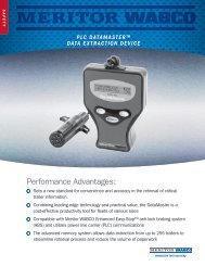
Section 1Introduction<strong>ABS</strong> ComponentsFigure 1.3Figure 1.11 Cab-Mounted2 Frame-MountedThe Electronic Control Unit (ECU) is the brain ofthe system. It receives in<strong>for</strong>mation from thesensors and sends signals to the <strong>ABS</strong> valves.The ECU may be mounted in the cab or on theframe of the vehicle. As illustrated, cab- andframe-mounted ECUs use a different styleconnector. Figure 1.1.A sensor is installed so that its end is against thetooth wheel. The sensor continuously sends wheelspeed in<strong>for</strong>mation to the ECU. On a four-channel<strong>ABS</strong>, two sensors are installed on the steering axleand two additional sensors are mounted on onedrive axle. The sensors on the steering axle areinstalled in the steering knuckle. The sensors onthe drive axle are mounted in a block attached tothe axle housing. Figure 1.3.Figure 1.4NOTEDo not open the ECU. Opening the ECU to gainaccess to the internal components will void thewarranty.Figure 1.2The sensor clip holds the sensor in place at thetooth wheel. Figure 1.4.The tooth wheel is mounted on the hub of eachmonitored wheel. Figure 1.2.Page 4
Section 1IntroductionFigure 1.5Figure 1.71 Out (Port 2)2 In (Port 1)An <strong>ABS</strong> modulator valve controls air pressure toeach affected brake during <strong>ABS</strong> function. Figure 1.5.During normal braking, compressed air flowsthrough the <strong>ABS</strong> valve to the brake chambers.During <strong>ABS</strong> operation, the <strong>ABS</strong> valve adjusts airpressure to the brake chambers to control brakingand prevent wheel lock.The <strong>ABS</strong> valve is usually located on a frame rail orcross member, between the relay valve or quickrelease valve and the brake chamber.1 Cab Harness2 Chassis HarnessThe in-cab ECU harness provides electricalconnections <strong>for</strong> the power, ground, warning lamp,and communication connections to the ECU.Depending on your vehicle set-up, it may alsoinclude the blink code switch and lamp. Figure 1.7.The chassis harness provides the electricalconnections <strong>for</strong> the sensors and valves.Figure 1.8Figure 1.6Sensor Extension Cables connect the sensor to theECU. Figure 1.8.An alternative to individual valves is the <strong>ABS</strong> valvepackage. It combines two <strong>ABS</strong> modulator valvesand one relay valve. Figure 1.6.Page 5
Section 1IntroductionFigure 1.9Optional Test Equipment:See Section 3, "Troubleshooting", <strong>for</strong>operating instructions.Figure 1.11The <strong>ABS</strong> Modulator Valve Cable connects the <strong>ABS</strong>valve to the ECU. Figure 1.9.Figure 1.10The <strong>Meritor</strong> <strong>WABCO</strong> test adaptor helps service andtroubleshoot the <strong>ABS</strong> system. Use withcab-mounted ECUs only. Figure 1.11.Figure 1.12The <strong>ABS</strong> warning lamp comes on when theignition switch is activated. The lamp goes outwhen the speed of the vehicle reachesapproximately 4 mph (6 km/h). If the warning lampremains lit or comes on at any other time duringvehicle operation, it signals a malfunction in the<strong>ABS</strong>. Figure 1.10.The MPSI Pro-Link ® 9000 with the <strong>Meritor</strong> <strong>WABCO</strong>cartridge, available from Kent-Moore, lets you test<strong>ABS</strong> components. Figure 1.12.Page 6
Section 2Automatic Traction Control (ATC)Section 2Automatic Traction Control (ATC)Optional ATCATC is an option available on <strong>ABS</strong>-equippedvehicles. It helps move vehicles on slipperysurfaces and reduces drive wheel overspin.ATC works automatically in two different ways:1. If a drive wheel starts to spin, ATC brakes thatwheel and transfers engine torque to thewheels with better traction.2. If all drive wheels spin, ATC reduces enginetorque to provide improved traction.If drive wheels spin during acceleration, the ATCindicator lamp comes on and stays lit. Todetermine if a vehicle has ATC, look <strong>for</strong> anindicator lamp on your dash or instrument panelmarked “ATC,” “ASR,” or “wheel spin.” (Somevehicles without ATC have a “wheel spin” lamp.)Figure 2.1.Figure 2.1Figure 2.2ATC ComponentsATC uses two solenoid valves, two double-checkvalves, and a wiring harness with ATC connectors.Figure 2.3Deep Snow and Mud SwitchA Deep Snow and Mud switch may be includedwith ATC. This feature increases available traction<strong>for</strong> vehicles on extra soft surfaces like slush ormud. The selection switch and indicator lamp arelocated on the dash. When this feature is selected,the indicator lamp blinks continuously. Figure 2.2.ATC solenoid valves are usually mounted on theframe toward the rear of the vehicle.The air line between the ATC valve and the doublecheck valve must gradually slope toward the ATCvalve. This allows condensation to drain out of theATC valve exhaust.See Section 3, "Troubleshooting", Section 4,"Removal & Installation", and Section 5, "Wiring"<strong>for</strong> additional ATC in<strong>for</strong>mation.Page 7
NotesPage 8
Section 3TroubleshootingSection 3TroubleshootingGeneral MaintenanceIn<strong>for</strong>mationThere is no regularly scheduled maintenancerequired <strong>for</strong> the <strong>Meritor</strong> <strong>WABCO</strong> <strong>ABS</strong> or <strong>ABS</strong>/ATC.However, <strong>ABS</strong> does not change current vehiclemaintenance requirements.TroubleshootingSuggested Diagnostic ToolsStandard: Blink Code Reference In<strong>for</strong>mation(see below).Optional: <strong>Meritor</strong> <strong>WABCO</strong> Test Adaptor.Optional: Pro-Link ® 9000.Blink Code Reference In<strong>for</strong>mationTo troubleshoot a possible <strong>ABS</strong> fault, use theblink code diagnostics built into the system. Be<strong>for</strong>eyou begin, you should be familiar with thefollowing definitions.Blink Code DefinitionsBlink Code: A series of blinks or flashes thatdescribe a particular <strong>ABS</strong> system configurationand fault.Blink Code Cycle: A set of three series of flashes,each set separated by a 2.5 second pause. The firstset of flashes represents the system set-up:1 flash = 6S/6M2 flashes = 4S/4M4 flashes = 6S/4MThe last two sets identify the system fault.Blink Code Switch: A switch that activates blinkcode diagnostic capabilities. Switch locations vary,depending on the make and model of the vehicle.Figure 3.1.CAUTIONYou must turn the blink code switch to the OFFposition be<strong>for</strong>e engaging in normal operation.If the switch is left in the ON position, reducedengine power can result (<strong>for</strong> vehicles equippedwith ATC only).Figure 3.11 Steering Column2 <strong>ABS</strong> Check Switch3 Engine Brake Relay4 Diagonal 1 10 Amp Fuse5 Diagonal 2 10 Amp Fuse6 Diagonal 1 Valve Relay (VR1)7 Warning Lamp Relay8 Diagonal 2 Valve Relay (VR2)9 ECU 5 Amp Fuse10 Blink Code Switch with LightPage 9
Section 3TroubleshootingErasing a fault: The process of clearing a fault fromthe ECU:1. After an Existing fault has been corrected2. After an Intermittent fault has been displayedAfter the fault has been cleared, the blink codedisplays a new code. Or, if there are no otherfaults, the blink code displays system O.K.(i.e., 2-0-0).Fault: An <strong>ABS</strong> malfunction detected and stored inmemory by the <strong>Meritor</strong> <strong>WABCO</strong> ECU. Systemfaults may be existing or intermittent.Existing Fault: An active <strong>ABS</strong> fault; <strong>for</strong> example, asensor circuit malfunction on the left front steeringaxle that currently exists. An existing fault must berepaired be<strong>for</strong>e it can be cleared from memory.Intermittent Fault: An inactive fault; <strong>for</strong> example, aloose wire that caused a system fault to register.An intermittent fault does not require repair be<strong>for</strong>eit can be cleared from memory.IF . . . <strong>ABS</strong> warning lamp comes onand stays on after:Ignition turned OFF, then ONandVehicle driven in excessof 4 mph (6 km/h) . . . . . . Fault is ExistingIF . . . <strong>ABS</strong> warning lamp comes onand stays on after:Vehicle driven in excessof 4 mph (6 km/h)and<strong>ABS</strong> warning lamp goes out after:Ignition turned OFF, then ONandVehicle again driven inexcess of 4 mph(6 km/h) . . . . . . . . . . Fault is IntermittentUsing the Blink CodeServicing AlertAn <strong>ABS</strong> warning lamp alerts drivers to a possiblesystem malfunction. If the <strong>ABS</strong> lamp stays onduring normal vehicle operation, the driver knowsthe vehicle needs to be serviced.Blink Code DisplayThe blink code is displayed on one of the followinglamps installed in the vehicle: An independent blink code lamp or acombination blink code switch and lamp. An ATC lamp located on the vehicle instrumentpanel (<strong>for</strong> <strong>ABS</strong>/ATC-equipped vehicles.)Lamp locations vary, depending on the make andmodel of the vehicle.Figures 3.2 and 3.3 illustrate the blink code cycle.Figure 3.2Figure 3.3Blink Code Facts As long as the ignition key and blink codeswitch remain in the ON position, the blinkcode will repeat. Intermittent fault codes can be erased fromthe ECU memory, but the condition that causedthe fault could still exist. Record intermittentfault codes and make any necessaryadjustments or repairs to the vehicle. After using the blink code, turn the blink codeswitch OFF be<strong>for</strong>e resuming normal operation.Page 10
Section 3TroubleshootingBlink Code Diagnostic Procedure Follow these steps to use the blink code:Step — Action System Response ActionITurn IgnitionKey ON.andTurn Blink CodeSwitch ON.IIIdentify the 3-digitblink code.IIIRepeat Step I todetermine status offault: Intermittent orExisting.<strong>ABS</strong> lamp comes on and stays on.Blink Code lamp comes on afterapproximately 5 seconds, then goes off.At the end of 5 seconds, blink codecycle begins.First set of flashes (indicates systemconfiguration).Pause. . . . . . . . . . . . . . . . . . . . Second set of flashes.Pause.Third set of flashes. . . . . . . . . . If a new code or a system O.K. code(i.e., 2-0-0) appears, fault wasIntermittent.NOTE: System O.K. code indicatesfault erased from ECU memory.If code repeats, fault is existing (active)and must be repaired.Observe lamps.Observe and record blink code.After blink code is identified, turn blink code switchOFF, cycle will continue until all three sets of flasheshave been displayed.After COMPLETE blink code cycle, turn ignition OFF.Look up 3-digit code on Diagnostics Chart or BlinkCode Card, TP-94157.Keep a record of fault <strong>for</strong> future reference.NOTE: Make necessary adjustments or repairs tovehicle to prevent future occurrences.Per<strong>for</strong>m repair listed on Diagnostics Chartor TP-94157.Repeat procedure until System O.K. code received.Working with Blink Code Diagnostics When using blink code diagnostics, the followingconditions may occur:Step Condition Cause ActionI Lamp does Loose or burned out bulb.Check bulb.not light.Check connections.Make necessary repairs.I, III Code continuesto repeat.Voltage not within acceptablerange (11-15 volts).Ignition and blink code switch notturned off.Check connections.Measure voltage.Make necessary repairs.Turn Blink Code switch off.Wait <strong>for</strong> lamp to stop flashing.Turn Ignition off.IICode not listed onDiagnostics Chartor TP-94157.Fault not repaired.Fault not erased from ECUafter report.Review Diagnostics Chart or TP-94157 to ensure allpossible conditions were corrected.Verify all repair work.Repeat procedure until System O.K. code received.Verify code (repeat Steps I and II).Contact <strong>Meritor</strong> <strong>WABCO</strong> Customer Service(800-535-5560) <strong>for</strong> assistance.Page 11
Section 3TroubleshootingBlink Code Diagnostics Use the following chart to identify blink codes.Additional 6S/6M and 6S/4M blink codes follow this table.Fault CodeBlink Code* Location Cause Solution1-0-02-0-04-0-01-6-62-6-64-6-61-6-72-6-74-6-71-6-82-6-84-6-81-6-92-6-94-6-91-6-102-6-104-6-101-6-112-6-114-6-111-6-122-6-124-6-121-6-132-6-134-6-131-7-02-7-04-7-01-7-12-7-14-7-11-7-22-7-24-7-21-7-32-7-34-7-31-7-42-7-44-7-41-7-52-7-54-7-5Page 12N/A No Faults — System O.K. No action needed.Voltage Relay 1Voltage Relay 2Right Front WheelLeft Front WheelRight Front WheelLeft Front WheelRight Front WheelLeft Front WheelLeft Rear WheelRight Rear WheelLeft Rear WheelRight Rear WheelLeft Rear WheelRight Rear WheelLow voltage to the diagonal relayor defective relay.Erratic wheel speed signal fromthe steering axle.Sensor circuit failure onsteering axle.Steering axle sensor outof adjustment.Erratic wheel speed fromdrive axle.Sensor circuit failure ondrive axle.Drive axle sensor outof adjustment.Check vehicle voltage orreplace relay if needed.Check <strong>for</strong> loose wheelbearings, faulty sensor wiringconnections, excessive hubrunout, a sensor gap that istoo wide, or damage to toothwheels on the steering axle.Check sensor, sensor cableand cable connections.Adjust sensors onsteering axle.Check <strong>for</strong> loose wheelbearings, faulty sensor wiringconnections, excessive hubrunout, sensor gap that is toowide, or damage to toothwheels on the drive axle.Check sensor, sensor cableand cable connections.Adjust sensors on drive axle.Check <strong>for</strong> differences betweensteer and drive tire sizes.* First digit of Blink Code identifies system configuration: 1 = 6S/6M, 2 = 4S/4M, 4 = 6S/4M.
Section 3TroubleshootingAdditional 6S/6M and 6S/4M blink codes follow this table.Fault CodeBlink Code* Location Cause Solution1-8-32-8-34-8-31-8-52-8-54-8-51-8-72-8-74-8-71-8-92-8-94-8-91-8-102-8-104-8-101-8-112-8-114-8-111-8-122-8-124-8-121-8-132-8-134-8-131-8-142-8-144-8-141-8-152-8-154-8-151-9-02-9-04-9-01-9-12-9-14-9-11-9-22-9-24-9-21-9-32-9-34-9-3N/AN/AN/AN/ARight Front WheelLeft Front WheelRight Front WheelLeft Front WheelRight Front WheelLeft Front WheelRight Front WheelLeft Front WheelLeft Rear WheelRight Rear WheelImproperly wired J1922 EngineData Link. Short circuit to poweror ground, or open circuit.Improperly wired J1922 EngineData Link. Short circuit to poweror ground, open circuit,wires switched.Message error detected in J1922Engine Data Link.Short circuit in steering axle <strong>ABS</strong>valve-to-ground connection.Open circuit in steering axle <strong>ABS</strong>valve or cable.Short circuit in steering axle <strong>ABS</strong>valve-to-ground connection.Open circuit in steering axle <strong>ABS</strong>valve or cable.Short circuit to ground in driveaxle <strong>ABS</strong> valve or cable.Check J1922 Engine Data Link,cable and connections.Check J1922 Engine Data Link,cable and connections.Erase fault from ECU memory.No other action required.Check <strong>ABS</strong> valve and cable.Replace as required.Check <strong>ABS</strong> valve and cable.Replace as required.Check <strong>ABS</strong> valve and cable.Replace as required.Check <strong>ABS</strong> valve and cable.Replace as required.Check <strong>ABS</strong> valve and cable.Replace as required.* First digit of Blink Code identifies system configuration: 1 = 6S/6M, 2 = 4S/4M, 4 = 6S/4M.Page 13
Section 3TroubleshootingAdditional 6S/6M and 6S/4M blink codes follow this table.Fault CodeBlink Code* Location Cause Solution1-9-42-9-44-9-41-9-52-9-54-9-51-9-62-9-64-9-61-9-72-9-74-9-71-9-82-9-84-9-81-9-92-9-94-9-91-10-22-10-24-10-21-10-32-10-34-10-31-10-42-10-44-10-41-10-52-10-54-10-51-10-72-10-74-10-71-10-82-10-84-10-81-10-92-10-94-10-91-11-122-11-124-11-121-11-132-11-134-11-13Left Rear WheelRight Rear WheelLeft Rear WheelRight Rear WheelLeft Rear WheelRight Rear WheelLeft Rear WheelRight Rear WheelLeft Rear WheelRight Rear WheelN/ALeft Rear WheelRight Rear WheelRight Front WheelLeft Front WheelOpen circuit in drive axle <strong>ABS</strong>valve or cable.Short circuit to ground in driveaxle <strong>ABS</strong> valve or cable.Open circuit in drive axle <strong>ABS</strong>valve or cable.Short circuit in ATC valve toground connection.Open circuit in ATC valveor cable.Short circuit in wiring or relaythat controls engine brake.Excessive drive axle wheelspin caused by driver ordynamometer.Short circuit between steeringaxle <strong>ABS</strong> valve and powersupply connection.Check <strong>ABS</strong> valve and cable.Replace as required.Check <strong>ABS</strong> valve and cable.Replace as required.Check <strong>ABS</strong> valve and cable.Replace as required.Check ATC valve and cable.Replace as required.Check ATC valve and cable.Replace as required.Check engine brake relay andwiring to relay coil.Check steer axle sensor gap.Erase fault from ECU memory.Check <strong>ABS</strong> valve and cable.Replace as required.* First digit of Blink Code identifies system configuration: 1 = 6S/6M, 2 = 4S/4M, 4 = 6S/4M.Page 14
Section 3TroubleshootingAdditional 6S/6M and 6S/4M blink codes follow this table.Fault CodeBlink Code* Location Cause Solution1-11-142-11-144-11-141-11-152-11-154-11-151-12-22-12-24-12-21-12-32-12-34-12-31-12-42-12-44-12-41-12-72-12-74-12-71-12-82-12-84-12-81-12-92-12-94-12-91-12-102-12-104-12-101-12-112-12-114-12-111-12-142-12-144-12-141-12-152-12-154-12-151-13-02-13-04-13-01-13-42-13-44-13-41-13-52-13-54-13-5Left Rear WheelRight Rear WheelLeft Rear WheelRight Rear WheelN/AN/ARight Front WheelLeft Front WheelLeft Rear WheelRight Rear WheelLeft Rear WheelRight Rear WheelN/AVoltage Relay 1Voltage Relay 2Short circuit between drive axle<strong>ABS</strong> valve and power supplyconnection.Short circuit between ATC valveand power supply connection.Short circuit between pin 12 of<strong>ABS</strong> ECU and power supplyconnection.Short circuit between enginebrake and ground connection.Short circuit between steeringaxle <strong>ABS</strong> valve and battery.Short circuit between steeringaxle <strong>ABS</strong> valve and battery.Short circuit between steeringaxle ATC valve and battery.Short circuit between pin 12 of<strong>ABS</strong> ECU and battery.Diagonal valve relay notoperating correctly.Check <strong>ABS</strong> valve and cable.Replace as required.Check ATC valve and cable.Replace as required.Check ECU harness.Check engine brake relay.Check <strong>ABS</strong> valve and cable.Replace as required.Check <strong>ABS</strong> valve and cable.Replace as required.Check ATC valve and cable.Replace as required.Check ECU harness.Check diagonal valve relay.* First digit of Blink Code identifies system configuration: 1 = 6S/6M, 2 = 4S/4M, 4 = 6S/4M.Page 15
Section 3TroubleshootingAdditional 6S/6M and 6S/4M blink codes follow this table.Fault CodeBlink Code* Location Cause Solution1-13-82-13-84-13-81-13-92-13-94-13-9Voltage Relay 1Voltage Relay 2Power supply voltage too high.Table B — Additional 6S/6M or 6S/4M Blink Codes: 4 = 6S/4M, 1 = 6S/6MRepair vehicle power supply.* First digit of Blink Code identifies system configuration: 1 = 6S/6M, 2 = 4S/4M, 4 = 6S/4M.Fault CodeBlink Code Axle 3Left1-7-84-7-81-7-104-7-101-7-124-7-12Right1-7-94-7-91-7-114-7-111-7-134-7-131-9-10 1-9-111-9-12 1-9-131-9-14 1-9-151-10-0 1-10-11-12-0 1-12-11-12-12 1-12-13CauseErratic wheel speed fromthird axle.Sensor circuit failure onthird axle.Third axle sensor out ofadjustment.Short circuit to ground in thirdaxle <strong>ABS</strong> valve or cable.Open circuit in third axle <strong>ABS</strong>valve or cable.Short circuit to ground in thirdaxle <strong>ABS</strong> valve or cable.Open circuit in third axle <strong>ABS</strong>valve or cable.Short circuit in connectionbetween third axle <strong>ABS</strong> valveand battery.Short circuit in connectionbetween third axle <strong>ABS</strong> valveand battery.SolutionCheck <strong>for</strong> loose wheel bearings, faulty sensorwiring connections, excessive hub runout,sensor gap that is too wide or damage to toothwheels on third axle.Check sensor, sensor cable and cableconnections.Adjust sensors on third axle. Check <strong>for</strong>differences between steer and rear tire sizes.Check <strong>ABS</strong> valve and cable. Replace as required.Check <strong>ABS</strong> valve and cable. Replace as required.Check <strong>ABS</strong> valve and cable. Replace as required.Check <strong>ABS</strong> valve and cable. Replace as required.Check <strong>ABS</strong> valve and cable. Replace as required.Check <strong>ABS</strong> valve and cable. Replace as required.Page 16
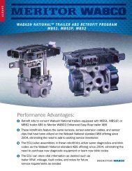
TestingSection 3TroubleshootingThe locations of sensors and valves are illustrated in Figures 3.4–3.9. Most vehicles with spring suspensionhave sensors on <strong>for</strong>ward-rear axle. Most vehicles with air suspension have sensors on rear-rear axle.Figure 3.4Figure 3.5Figure 3.6Liftable axles are always the third axle with <strong>ABS</strong>.Page 17
Section 3TroubleshootingFigure 3.7Figure 3.8Figure 3.9Page 18Liftable axles are always the third axle with <strong>ABS</strong>.
Section 3TroubleshootingOptional Test EquipmentWARNINGSExhaust gas contains poison. When testinga vehicle with the engine running, test in awell-ventilated area or route the exhausthose outsideTo avoid serious personal injury, keep away,and keep test equipment away, from all moving orhot engine parts.NOTES Refer to, and follow, the vehicle manufacturer'sWarnings, Cautions, and Service Procedures. Unless otherwise directed, set the parking brakeand place the gear selector in NEUTRAL(manual transmission) or PARK (automatictransmission).<strong>Meritor</strong> <strong>WABCO</strong> Test Adaptor For use with cab-mounted ECUs only.CAUTIONWhen troubleshooting or testing the system at themain connector, be careful not to damage theelectrical sockets.Use the <strong>Meritor</strong> <strong>WABCO</strong> test adaptor to measurethe resistance across the harness pins.When a test involves testing the cable harness, usethe diagram in Figure 3.10 to identify pin locationson the 35-pin connector.Figure 3.10Volt-Ohm Meter (VOM)The receptacles in the test adaptor accept thetips of standard VOM cables. These tips areapproximately 0.080-inch diameter (2 mm). Use agood quality digital or analog VOM.A VOM with automatic polarity sensing isrecommended. This eliminates worry over polarityof the meter leads during voltage measurements.Component TestsComponent tests <strong>for</strong> tractor, truck, and busapplications are: Vehicle voltages Sensors <strong>ABS</strong> modulator valves ATC valves <strong>ABS</strong>/ATC lamps <strong>ABS</strong>/ATC switchesTesting ProcedureTo use the <strong>Meritor</strong> <strong>WABCO</strong> test adaptor:1. Determine the failure code and meaning (see“Blink Code Diagnostic Charts”).2. Turn vehicle ignition OFF.3. Disconnect the 35-pin harness connector fromthe ECU.4. Insert the test adaptor into the 35-pinharness connector.5. Check the following table to determine whichadaptor pins to test with the VOM.6. Set the VOM to the appropriate scale.7. Take measurement and write it down.8. Compare measurement with the desiredmeasurement value listed in Table 1 — TestAdaptor Measurement Checks.9. Repair or replace wiring or componentas necessary.10. Disconnect the test adaptor from the harnessand reconnect the harness to the ECU.11. Make sure the <strong>ABS</strong> is functional; road test thevehicle if necessary.Page 19
Section 3TroubleshootingTable 1 — Test Adaptor Measurement ChecksCAUTIONThe following tests could damage the measuringinstruments or the <strong>ABS</strong> and/or ATC valves beingtested. If you do not know how to use a VOM, donot conduct these tests.If the VOM is not connected properly, damage tothe meter could result.Valves should not be left connected to power(pin 9) <strong>for</strong> more than 10 seconds or the valve maybe damaged. Adhere to all safety warnings and cautions (see“<strong>Meritor</strong> <strong>WABCO</strong> Test Adaptor”) when usingthe test adaptor. Always per<strong>for</strong>m the tests inTable 1 be<strong>for</strong>e attempting the Valve FunctionTests in Table 2.Test orMeasurementVoltage to ECUValve RelayVoltageWarning LightWiringATC/DiagnosticLight WiringDiagnosticSwitch WiringSpeed SensorResistanceSpeed SensorResistance toGroundSpeed SensorAdjustment<strong>ABS</strong> Valve CoilResistanceATC Valve CoilResistanceVOM Setting(Test AdaptorPins)Volts DC+9 & –27Volts DCVR1+1 & –27VR2+19 & –27Ohms26 & 9Ohms3 & 9Ohms14 & 27OhmsLF 15 & 32RF 17 & 34LR 18 & 35RR 16 & 33OhmsLF 15 & 27RF 17 & 27LR 18 & 27RR 16 & 27Volts ACLF 15 & 32RF 17 & 34LR 18 & 35RR 16 & 33OhmsLF In 23 & 27Exh 24 & 27RF In 6 & 27Exh 7 & 27LR In 21 & 27Exh 22 & 27RR In 4 & 27Exh 5 & 27OhmsLR 2 & 27RR 20 & 27OtherActionPress/togglediag. switchTurn wheelby hand at30 RPM(2 sec./rev.)VehicleIgnitionOFFONOFFOFFOFF(Record)ActualMeasurementDesiredMeasurement0.0 volts11.0-15.0 volts0.0 volts0.0 volts2-50 ohms(typical)2-50 ohms(typical)Possible Causes ofMalfunctionConstant power to ECUBlown fusePower to ECU interruptedVR1 or VR2 relay contactsstickingBulb/LEDWiring to warning lightinterruptedATC/diagnostic light wiringBulb/LEDWiring to ATC/diagnosticlight interruptedOFF 0-2 ohms Switch Wiring to switch isinterruptedOFF 700-3000 ohms Broken wire between ECUand sensor Sensor connector Defective sensorOFF > 30K ohms Shorted sensor wire Chafed/cut sensor cable Defective sensorOFF > 0.200 VAC No reading— Sensor wire broken— Sensor wire shorted Sensor gap too large Large variation— Excessive tone ringrunout— Tone ring damaged— Excessive wheelbearing end playOFFOFF4-8 ohms4-8 ohms8-14 ohms8-14 ohmsWiring between ECU andvalve interruptedGround lead to valveinterruptedShorted valve coil Wiring between ECU andvalve interrupted Ground lead to valveinterrupted Shorted valve coilPage 20
Section 3TroubleshootingTable 2 — <strong>ABS</strong> and ATC Valve Function TestsCAUTIONThe word TOUCH means connect the appropriatelead to pin 9 only when ready to observe the results.Conduct the <strong>ABS</strong> and ATC valve Function Testsonly if the Measurement Checks in Table 1 yieldedinconclusive results. This could occur because ofimproper plumbing to the <strong>ABS</strong> or ATC valves orbecause the wiring to the <strong>ABS</strong> valves has the inletand exhaust portions of the solenoid interchanged.In either case, the ECU may not detect the errorand it will be necessary to manually activate thevalves to confirm correct function. Adhere to the cautions listed <strong>for</strong> Table 1 whenper<strong>for</strong>ming the following tests. Adhere to all safety warnings and cautions (see“<strong>Meritor</strong> <strong>WABCO</strong> Test Adaptor”) when using thetest adaptor. Always per<strong>for</strong>m the tests in Table 1 be<strong>for</strong>eattempting the Valve Function Tests in Table 2.TestVOM settingTest AdaptorPinsVehicleIgnition Additional Action Desired ResultsPossible Causes ofMalfunction<strong>ABS</strong>ValveFunction10 AmpsLF: Exh (+) to 9In (+) to 9ONApply and maintainbrake application TOUCH (–) to 24 -----> Release brake TOUCH (–) to 23 Apply brake ------------>Left front chamber exhaustscontinuouslyNo pressure build-up in LFchamber Wiring to valve isinterchanged Valve plumbing isincorrect Valve defective10 AmpsRF: Exh (+) to 9ONApply and maintainbrake application TOUCH (–) to 7 -------> Release brakeRight front chamber exhaustscontinuouslyIn (+) to 910 AmpsLR: Exh (+) to 9In (+) to 9ON TOUCH (–) to 6 Apply brake ------------>Apply and maintainbrake application TOUCH (–) to 22 -----> Release brake TOUCH (–) to 21 Apply brake ------------>No pressure build-up in RFchamberLeft rear chamber(s) exhaustscontinuouslyNo pressure build-up in LRchamber(s)10 AmpsRR: Exh (+) to 9ONApply and maintainbrake application TOUCH (–) to 5 -------> Release brakeRight rear chamber(s)exhausts continuouslyIn (+) to 9 TOUCH (–) to 4 Apply brake ------------>No pressure build-up in RRchamber(s)ATCValveFunction10 AmpsLR (+) to 9RR (+) to 9ON TOUCH (–) to 2 TOUCH (–) to 20Pressure build-up in LRchamber(s)Pressure build-up in RRchamber(s) Plumbing to ATCvalve blocked,incorrect Valve defectivePage 21
Section 3TroubleshootingFinal Test <strong>for</strong> a TractorEquipped with <strong>ABS</strong>NOTETurn the blink code switch to the OFF position.Complete the following test.For a Tractor Equipped with <strong>ABS</strong>:1. Check that the cab harness is attached tothe ECU.2. Start the engine.3. Increase vehicle speed. At about 4 mph(6 km/h), the tractor warning light must to out.NOTES If the tractor warning light continues tostay on, check blink codes, all componentsand connections. When failures cannot be repaired, contactyour <strong>Meritor</strong> District Service Manager at800-535-5560 in the U.S. and Canada.MPSI Pro-Link ® 9000Use the Pro-Link ® 9000 to: Diagnose System Faults on <strong>ABS</strong> and <strong>ABS</strong>/ATCsystems with C2 and C3 ECUs. (May be used inplace of blink code diagnostic procedures.) Per<strong>for</strong>m component measurement andfunction tests.NOTEPro-Link ® screens identify faults as existingor stored. See “Blink Code Definitions”<strong>for</strong> definitions.Component TestsComponents that may be tested with thePro-Link ® 9000 are: Vehicle Voltages <strong>ABS</strong> Modulator Valves ATC Valves <strong>ABS</strong>/ATC Lamps Sensors Engine Datalink Retarder Relay Retarder Datalink <strong>ABS</strong>/ATC SwitchesNOTEAdhere to all safety Warnings and Cautions (see“<strong>Meritor</strong> <strong>WABCO</strong> Test Adaptor”).Diagnostic and Testing Procedure1. Locate the 6-pin connector in the vehicle cab.Gather together everything you need duringthe test. Pro-Link ® 9000 <strong>Meritor</strong> <strong>WABCO</strong> test cartridge 6-pin connector2. Slide the <strong>Meritor</strong> <strong>WABCO</strong> cartridge into thePro-Link ® keypad until connection is tight.Figure 3.11.Figure 3.113. Chock the wheels, apply the parking brake, andmake sure ignition power is off.WARNINGBlock the wheels to prevent the vehicle frommoving. Support the vehicle with safety satnds.Do not work under a vehicle supported only byjacks. Jacks can slip and fall over. Serious personalinjury can result.4. Connect the Pro-Link ® to the 6-pin connectoron the ECU.5. Turn the ignition to the ON/RUN position.6. Check the Pro-Link ® screen to make sure itpowers up.If the Pro-Link ® does not power up or if thescreen indicates “NO DATA RECEIVED:” Check connections. Make sure the cartridge is properlyconnected to the Pro-Link ® keypad. Verify 12 volts DC power and ground at theconnector and <strong>ABS</strong> ECU. Check the fuse panel <strong>for</strong> a blown fuse. Check <strong>for</strong> proper wiring in the diagnosticconnector.7. Refer to the Pro-Link ® manual <strong>for</strong> completediagnostic and testing instructions.Page 22
Section 3TroubleshootingTesting and Diagnostic ScreensFigure 3.14NOTEThe menu selections <strong>for</strong> the Pro-Link ® are describedbelow. Refer to the Pro-Link ® manual <strong>for</strong> completetesting instructions.Vehicle VoltagesFigure 3.12 Selected <strong>ABS</strong> modulator valve is cycled 15 times. A faint clicking of the internal solenoid is heard 15times during this test. No change in air chamber pressure should occur.ATC ValvesFigure 3.15Monitors the two voltage signals poweringthe ECU.<strong>ABS</strong> Modulator Valves (Two Tests)Choose from four or six valves: For 4S/4M or 6S/4M systems chooseL Front Valve L 2nd Axle ValveR Front Valve R 2nd Axle Valve For 6S/6M there are two additional valves:R Third Axle Valve L Third Axle Valve Exercises <strong>ABS</strong> modulator valves one at a time.Figure 3.13 Exercises the left and right rear ATC valves,one at a time. Valve is cycled 15 times <strong>for</strong> a period ofsix seconds.<strong>ABS</strong>/ATC LampsFigure 3.16With brake applied: Selected <strong>ABS</strong> modulator valve will showdecreased air chamber pressure. Test has four cycles, each with three decreasesof pressure. Cycles are separated by a pause.Monitors the <strong>ABS</strong> and ATC indicator lamps on theinstrument panel.Page 23
Section 3TroubleshootingSensorsFigure 3.17Retarder DatalinkFigure 3.20Rotate wheel: Monitors the inputs to the ECU from the wheelsensors, one at a time.Engine Datalink (ATC vehicles only)Checks wiring connections.<strong>ABS</strong>/ATC SwitchesFigure 3.21Figure 3.18Checks status of <strong>ABS</strong> and ATC/Deep Snow-Mudswitches on the instrument panel.Reduces engine torque to verify proper wiring.Retarder RelayFigure 3.19 Verifies relay is functioning properly (a clickshould be heard). Checks wiring connections.Testing ComponentsIf the blink codes or MPSI Pro-Link ® indicate aproblem with an <strong>ABS</strong> or <strong>ABS</strong>/ATC component,always check the wiring or connections be<strong>for</strong>ereplacing the component. In your preliminarycheck look <strong>for</strong>: Loose connections Corrosion BreakageSee “<strong>Meritor</strong> <strong>WABCO</strong> Test Adaptor” in this section<strong>for</strong> in<strong>for</strong>mation. The adaptor makes checkingresistance across the harness pins easier.CAUTIONWhen troubleshooting and testing the <strong>ABS</strong>system at the main ECU connector, be carefulnot to damage the electrical sockets on theECU connector.Page 24
Section 3TroubleshootingIgnition VoltageVoltage must be between 11.0 and 15.0 v. Measurevoltage between pin 9 and pin 27 on cab mountsystems and between 10 and 12 on the 19-pinconnector on frame-mounted ECUs with ignition on.Sensor ResistanceThe sensor circuit resistance must be700-3000 ohms. Resistance can be measured atthe sensor connector when it is removed fromthe ECU, or right at the sensor when the extensioncable is removed.Sensor AdjustmentNOTEOn the steering axle the sensor is accessible on thein-board side of the steering knuckle.On the drive axle the wheel and drum assemblymust be pulled to gain access to the sensor.Gently push the sensor in toward the tooth wheeluntil it contacts the tooth wheel. When the resistance is greater than 8.0 ohms,clean the electrical contacts in the solenoid. Check the resistance again. To check the cable and the <strong>ABS</strong> valve as one unit,measure across the pins on the ECU connectorof the cab harness. Reference the diagram of thesystem you are testing <strong>for</strong> pin numbers (seeSection 5, "Wiring").ATC ValveThe resistance across the two electrical terminalson the ATC valve must be 8.0 to 14.0 ohms.Figure 3.23.Figure 3.23<strong>ABS</strong> Valve The resistance across each valve solenoid coilterminal and the ground on the <strong>ABS</strong> valveconnector must be 4.0 to 8.0 ohms. Figure 3.22.Figure 3.221 Ground Terminal2 Exhaust Solenoid3 Inlet Solenoid If the resistance is greater than 14.0 ohms, cleanthe electrical contacts on the solenoid. Check the resistance again. To check the cable and ATC valve as one unit,measure the resistance across the pins:— Use the connector at the connection point ofthe ECU <strong>for</strong> frame mounts— Use the <strong>Meritor</strong> <strong>WABCO</strong> test adaptor <strong>for</strong>cab mounts Reference the diagram of the system you aretesting <strong>for</strong> pin numbers (see Section 5, "Wiring").Page 25
Section 3TroubleshootingDynamometer Testing Vehicleswith ATCWARNINGFailure to disable the ATC be<strong>for</strong>e dynamometertesting could result in serious personal injury anddamage to the vehicle.Vehicles with the ATC option must have the <strong>ABS</strong>system power disabled to test the vehicle on adynamometer. The method requires removing the“<strong>ABS</strong>” circuit breaker/fuse or removing the ECUmain connector. Disconnect connector or breakerwith ignition in the OFF position.Tire Size RangeCAUTIONFor proper <strong>ABS</strong>/ATC operation with the standardElectronic Control Unit (ECU), front and reartire sizes must be within ± 5% of each other.When this tire size range is exceeded withoutelectronically modifying the ECU, the systemper<strong>for</strong>mance can be affected and the warning lampcan illuminate. Call <strong>Meritor</strong> <strong>WABCO</strong> at800/535-5560 when you plan a tire size differencegreater than 5%.Calculate tire size with the following equation:% Difference = (RPM Steer ÷ RPM Drive — 1) x 100RPM = tire revolutions per milePage 26
Section 4Removal & InstallationSection 4Removal & InstallationComponent Removaland InstallationFigure 4.1WARNINGTo prevent serious eye injury, always wear safeeye protection when you per<strong>for</strong>m vehiclemaintenance or service.CAUTIONUse the following procedures to avoid damage tothe electrical system and <strong>ABS</strong>/ATC components.When welding on an <strong>ABS</strong>- or <strong>ABS</strong>/ATC-equippedvehicle is necessary, disconnect power and groundleads from the ECU.SensorsWheel Speed Sensor Removal —Front AxleTo remove the sensor from the front axle:1. Put blocks under the rear tires to stop thevehicle from moving. Apply the parking brake.WARNINGBlock the wheels to prevent the vehicle frommoving. Support the vehicle with safety satnds.Do not work under a vehicle supported only byjacks. Jacks can slip and fall over. Serious personalinjury can result.2. Raise the front tires off the ground. Put safetystands under the axle.3. Remove the sensor from the steering knuckle.Use a twisting motion if necessary. Do not pullon the cable. Figure 4.1.4. Disconnect the fasteners that hold the sensorcable to other components.5. Disconnect the sensor cable from thechassis harness.See “Sensor Resistance” and “SensorAdjustment” <strong>for</strong> additional sensor in<strong>for</strong>mation.Wheel Speed Sensor Installation —Front AxleTo replace the sensor in the front axle:1. Connect the sensor cable to the chassis harness.2. Install the fasteners used to hold the sensorcable in place.3. Apply a mineral oil-based lubricant that containsmolydisulfide to the sensor spring clip and tothe body of the sensor. The lubricant shouldhave excellent anti-corrosion and adhesioncharacteristics, and be capable of continuousfunction in a temperature range of –40° to 300°F(–40° to 150°C).4. Install the sensor spring clip. Make sure theflange stops are on the inboard side ofthe vehicle.5. Push the sensor spring clip into the bushing inthe steering knuckle until the clip stops.6. Push the sensor completely into the sensorspring clip until it contacts the tooth wheel.7. Remove the blocks and safety stands.Wheel Speed Sensor Removal —Rear AxleTo remove the sensor from the rear axle:WARNINGBlock the wheels to prevent the vehicle frommoving. Support the vehicle with safety satnds.Do not work under a vehicle supported only byjacks. Jacks can slip and fall over. Serious personalinjury can result.1. Put blocks under the front tires to stop thevehicle from moving.Page 27
Section 4Removal & Installation2. Raise the rear tire off the ground. Put safetystands under the axle.3. Release the parking brake and back off theslack adjuster to release the brake shoes.4. Remove the wheel and tire assembly fromthe axle.5. Remove the brake drum.6. Remove the sensor from the mounting block inthe axle housing. Use a twisting motion ifnecessary. Do not pull on the cable.7. Remove the sensor spring clip from themounting block.8. Disconnect the fasteners that hold thesensor cable and the hose clamp toother components.9. Disconnect the sensor cable from thechassis harness.Wheel Speed Sensor Installation —Rear Axle1. Apply a mineral oil-based lubricant thatcontains molydisulfide to the sensor springclip and to the body of the sensor. Thelubricant should have excellent anti-corrosionand adhesion characteristics, and be capable ofcontinuous function in a temperature range of–40° to 300°F (–40° to 150°C).2. Install the sensor spring clip. Make sure theflange stops are on the inboard side ofthe vehicle.3. Push the sensor spring clip into the mountingblock until it stops.4. Push the sensor completely into the sensorspring clip until it contacts the tooth wheel.Figure 4.2.5. Insert the sensor cable through the hole in thespider and axle housing flange. Route thecable to the frame rail. Be sure to route thecables in a way that will prevent pinching orchafing and will allow sufficient movement <strong>for</strong>suspension travel.Figure 4.21 Spring Clip2 Sensor Holder3 Spring Clip Tab4 Sensor6. Connect the sensor cable to thechassis harness.7. Install the fasteners that hold the sensorcable in place.8. Install the brake drum on the wheel hub.9. Complete the installation per vehiclemanufacturer's manual.Valves<strong>ABS</strong> Modulator Valve Removal1. Turn ignition switch to the OFF position, applyparking brake.2. Put blocks under the front and rear tires to stopthe vehicle from moving.WARNINGBlock the wheels to prevent the vehicle frommoving. Support the vehicle with safety satnds.Do not work under a vehicle supported only byjacks. Jacks can slip and fall over. Serious personalinjury can result.3. If necessary, raise the vehicle off the groundand put safety stands under the axle.4. Disconnect the wiring connector from the<strong>ABS</strong> valve.Page 28
Section 4Removal & Installation5. Disconnect the air lines from Ports 1 (airsupply) and 2 (air discharge) of the <strong>ABS</strong> valve.Figure 4.3.Figure 4.36. Remove the two mounting capscrews andnuts.7. Remove the <strong>ABS</strong> valve.<strong>ABS</strong> Modulator Valve InstallationCAUTIONMoisture can affect the per<strong>for</strong>mance of all<strong>ABS</strong>/ATC systems, as well as the standard brakingsystem. Moisture in air lines can cause air lines tofreeze in cold weather.Installation Guidelines: Use thread sealant correctly to avoid air lineleaks in pneumatic connections. Follow supplier recommendations.To install the <strong>ABS</strong> modulator valve:1. Install the <strong>ABS</strong> valve with two mountingcapscrews and nuts. Tighten the capscrews perthe manufacturer's recommendation.2. Connect the line to the brake chambers to port2 of the <strong>ABS</strong> valve. Connect the air supply lineto port 1 of the <strong>ABS</strong> valve.3. Connect the wiring connector to the <strong>ABS</strong> valve.4. Remove the blocks and stands.ATC Valve Removal1. Turn ignition switch to the OFF position, applyparking brake.WARNINGBlock the wheels to prevent the vehicle frommoving. Support the vehicle with safety satnds.Do not work under a vehicle supported only byjacks. Jacks can slip and fall over. Serious personalinjury can result.2. Put blocks under the front and rear tires to stopthe vehicle from moving.3. If necessary, raise the vehicle off the groundand put safety stands under the axle.4. Disconnect the wiring from the ATC valve.5. To relieve line pressure, bleed the air from theappropriate supply tank.6. Disconnect the air lines from Ports 1 (airsupply) and 2 (air discharge) of the ATC valve.7. Remove the two mounting capscrews andnuts.8. Remove the ATC valve.ATC Valve InstallationInstallation Guidelines: Use thread sealant correctly to avoid air lineleaks in pneumatic connections. Follow supplier recommendations.To install the ATC valve:1. Install the ATC valve with two mountingcapscrews and nuts. Tighten the capscrews perthe manufacturer's recommendation.2. Connect the line from the double check valve toport 2 of the ATC valve. Connect the air supplyline to port 1 of the ATC valve.3. Connect the harness connector to theATC valve.4. Remove the blocks and stands.<strong>ABS</strong> Valve PackageIf you are servicing a vehicle with an <strong>ABS</strong> ValvePackage, you will need TP-95144, Servicing the<strong>ABS</strong> Valve Package. Contact <strong>Meritor</strong> <strong>WABCO</strong> at800-535-5560 <strong>for</strong> this literature.Page 29
Section 5WiringSection 5WiringThis section contains <strong>ABS</strong> wiring diagrams and connector pin callouts. If you have any questions, pleasecontact <strong>Meritor</strong> Customer Service at 800-535-5560.Figure 5.1Page 30
Section 5Wiring<strong>ABS</strong>/ATC Wiring SchematicCab-Mounted ECUFigure 5.2Page 31
Section 5Wiring<strong>ABS</strong>/ATC Wiring SchematicFrame-Mounted ECU Left/Right Harness ConfigurationFigure 5.3Page 32
Section 5WiringFigure 5.4Page 33
Section 5Wiring<strong>ABS</strong>/ATC Wiring SchematicFrame-Mounted ECU Front/Rear Harness ConfigurationFigure 5.5Page 34
Section 5WiringFigure 5.6Page 35
Section 5WiringFront/Rear ConfigurationsFigure 5.7Page 36
Section 5WiringLeft/Right ConfigurationsFigure 5.8Page 37
Section 5WiringIn-Cab ECU Wiring DiagramFigure 5.9Page 38
Section 5WiringIn-Cab ECU Wiring DiagramFigure 5.10Page 39
<strong>Meritor</strong> <strong>WABCO</strong>Vehicle Control <strong>Systems</strong>2135 West Maple RoadTroy, MI 48084 U.S.A.800-535-5560www.meritorauto.comIn<strong>for</strong>mation contained in this publication was in effect at the time the publication was approved <strong>for</strong>printing and is subject to change without notice or liability. <strong>Meritor</strong> <strong>WABCO</strong> reserves the right torevise the in<strong>for</strong>mation presented or discontinue the production of parts described at any time.© Copyright 1998Maintenance Manual No. 28<strong>Meritor</strong> <strong>WABCO</strong> Printed in the USA Revised 4/98All Rights ReservedPlease Recycle16579/<strong>Meritor</strong>