programmable vehicle speedometers - Veethree Instruments
programmable vehicle speedometers - Veethree Instruments
programmable vehicle speedometers - Veethree Instruments

You also want an ePaper? Increase the reach of your titles
YUMPU automatically turns print PDFs into web optimized ePapers that Google loves.
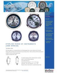
PROGRAMMABLE<br />
VEHICLE<br />
SPEEDOMETERS<br />
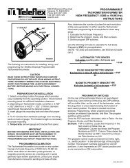
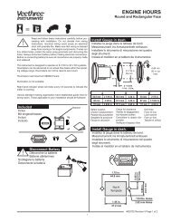
FIGURE 1<br />
INSTALLATION OF GAUGE<br />
After checking fit of gauge and U bracket, insert<br />
gauge into panel and install bracket over mounting<br />
studs. Install a washer and nut onto each mounting<br />
stud as shown in Figure 1.<br />
CAUTION:<br />
MAKE SURE THAT ELECTRICAL WIRING IS<br />
DRESSED AWAY FROM MOVING OR HOT ENGINE<br />
COMPONENTS.<br />
These instructions for installing, wiring, and<br />
programming the <strong>Veethree</strong> Programable<br />
Speedometer with Odometer should be kept with the<br />
<strong>vehicle</strong>.<br />
CAUTION<br />
READ THESE INSTRUCTIONS THOROUGHLY BEFORE<br />
PROCEEDING WITH INSTALLATION. DO NOT DEVIATE<br />
FROM WIRING INSTRUCTIONS. INCORRECT WIRING<br />
COULD CAUSE ELECTRICAL SHORT AND POSSIBLE<br />
FIRE. ALWAYS DISCONNECT POSITIVE LEAD FROM<br />
BATTERY BEFORE MAKING ANY ELECTRICAL<br />
CONNECTIONS.<br />
NOTE:If you must use a 12vdc unit in a 24vdc system,<br />
use a Voltage Reducer, <strong>Veethree</strong> Part Number<br />
6221776 in the "IGN" lead, and change light bulb to<br />
<strong>Veethree</strong> part number 40102-007 or equal (GE400).<br />
PREPARATION FOR INSTALLATION<br />
1. Select a mounting location for gauge which provides<br />
easy readability from the operating position.<br />
Check behind mounting panel for sufficient installation<br />
clearance.<br />
2.Depending on Speedometer model, cut either a<br />
3.395" +/- .032" (86 mm) or 4.625 (118mm) diameter<br />
hole through the panel at the desired location.<br />
3. Insert gauge into mounting hole and check for fit.<br />
4. Fit U bracket from hardware package over<br />
mounting studs on back of gauge (See Figure 1).<br />
Legs of bracket may be shortened if required.<br />
IMPORTANT:<br />
BEFORE PROCEEDING WITH INSTALLATION<br />
AND FINAL WIRING, SPEEDOMETER MUST BE<br />
PROPERLY PROGRAMMED TO OPERATE WITH<br />
YOUR EQUIPMENT. REFER TO THE<br />
PROGRAMMING SECTION OF THIS BULLETIN<br />
BEFORE PROCEEDING.<br />
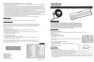
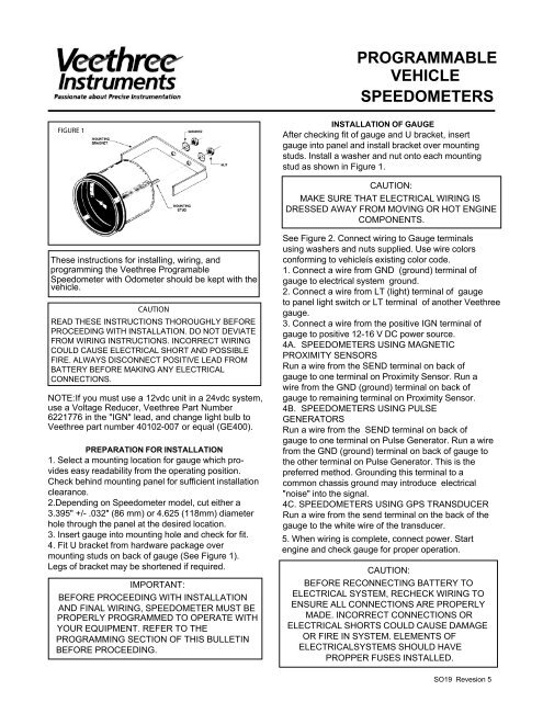
See Figure 2. Connect wiring to Gauge terminals<br />
using washers and nuts supplied. Use wire colors<br />
conforming to <strong>vehicle</strong>ís existing color code.<br />
1. Connect a wire from GND (ground) terminal of<br />
gauge to electrical system ground.<br />
2. Connect a wire from LT (light) terminal of gauge<br />
to panel light switch or LT terminal of another <strong>Veethree</strong><br />
gauge.<br />
3. Connect a wire from the positive IGN terminal of<br />
gauge to positive 12-16 V DC power source.<br />
4A. SPEEDOMETERS USING MAGNETIC<br />
PROXIMITY SENSORS<br />
Run a wire from the SEND terminal on back of<br />
gauge to one terminal on Proximity Sensor. Run a<br />
wire from the GND (ground) terminal on back of<br />
gauge to remaining terminal on Proximity Sensor.<br />
4B. SPEEDOMETERS USING PULSE<br />
GENERATORS<br />
Run a wire from the SEND terminal on back of<br />
gauge to one terminal on Pulse Generator. Run a wire<br />
from the GND (ground) terminal on back of gauge to<br />
the other terminal on Pulse Generator. This is the<br />
preferred method. Grounding this terminal to a<br />
common chassis ground may introduce electrical<br />
"noise" into the signal.<br />
4C. SPEEDOMETERS USING GPS TRANSDUCER<br />
Run a wire from the send terminal on the back of the<br />
gauge to the white wire of the transducer.<br />
5. When wiring is complete, connect power. Start<br />
engine and check gauge for proper operation.<br />
CAUTION:<br />
BEFORE RECONNECTING BATTERY TO<br />
ELECTRICAL SYSTEM, RECHECK WIRING TO<br />
ENSURE ALL CONNECTIONS ARE PROPERLY<br />
MADE. INCORRECT CONNECTIONS OR<br />
ELECTRICAL SHORTS COULD CAUSE DAMAGE<br />
OR FIRE IN SYSTEM. ELEMENTS OF<br />
ELECTRICALSYSTEMS SHOULD HAVE<br />
PROPPER FUSES INSTALLED.<br />
SO19 Revesion 5
FIGURE 2<br />
WIRING DIAGRAM<br />
PROGRAMMING THE SPEEDOMETER<br />
The speedometer is accurate on any system having a frequency at full scale between:<br />
DIAL RANGE: FULL SCALE FREQUENCY DIAL RANGE: FULL SCALE FREQUENCY<br />
0-30 mph 265-6599 Hz. 0-50 km/h 444-10,999 Hz.<br />
0-85 mph 91-2337 Hz. 0-140 km/h 77-1924 Hz.<br />
0-120 mph 133-3299 Hz. 0-160 km/h 89-2199 Hz.<br />
0-160 mph 178-4399 Hz.<br />
Programming the speedometer is accomplished in three steps:<br />
STEP 1 . Determine the Full Scale Frequency (F.S.F.).<br />
STEP 2. Calculate the Divide Number.<br />
STEP 3. Program the DIP switch “Program” section.<br />
STEP 1: Determine the full scale frequency (F.S.F)<br />
NOTE: The tire revs/mile (or KM) may be obtained from the tire manufacturer; the number of pulses per generator revolution<br />
from the pulse generator supplier, the rear axle ratio may be obtained from the chassis manufacturer; and the number of<br />
drive and driven gear teeth may be obtained from the transmission or chassis manufacturer.<br />
A. If using wheel mounted magnetic proximity sensor:<br />
Tire Revs/Mile (or KM) x # of Teeth (or Slots) on wheel x Constant see below) . = F.S.F<br />
DIAL RANGE: CONSTANT(f): DIAL RANGE: CONSTANT(f):<br />
0-30 MPH 0.0083 0-50 KM/H 0.0138<br />
0-85 MPH 0.0236 0-140 KM/H 0.0388<br />
0-120 MPH 0.0333 0-160 KM/H 0.0444<br />
0-160 MPH 0.0444<br />
EXAMPLE: 0-85 MPH Model: Tire Revs/Mile (or KM) x # of Teeth (or Slots) x Constant(f) = F.S.F<br />
988.7 x 90 x 0.0236 = 2100 Hz.<br />
B. If using transmission mounted pulse generator: (You must ascertain the number of pulses per revolution produced<br />
by the Pulse Generator used. If not one of the “pulses/rev” listed<br />
below, contact <strong>Veethree</strong> Technical Service. The <strong>Veethree</strong> Pulse<br />
Generator No. 9604276 is 8 pulses/revolution.<br />
Tire Revs/Mile (or KM) x Rear Axle Ratio x (# of Drive Gear Teeth) x (# of Driven Gear Teeth) = Pulse Gen.Revs/Mile(or KM)<br />
Pulse Gen.Revs/Mile(or KM) x Constant (see below) = F.S.F.<br />
DIAL<br />
CONSTANT with: DIAL<br />
CONSTANT with:<br />
RANGE 8 pulse/rev 16 pulse/rev 30 pulse/rev RANGE 8 pulse/rev 16 pulse/re 30 pulse/rev<br />
0-30 MPH 0.0666 0.1333 0.2500 0-50 KM/H 0.1111 0.2222 0.4166<br />
0-85 MPH 0.1888 0.3777 0.7083 0-140 KM/H 0.3111 0.6222 1.1666<br />
0-120 MPH 0.2666 0.5333 1.000 0-160 KM/H 0.3555 0.7111 1.3333<br />
0-160 MPH 0.3555 0.7111 1.3333<br />
EXAMPLE: 0-85 MPH Model, 8 pulse/rev. generator<br />
Tire Revs/Mile (or KM) x Rear Axle Ratio x (# of Drive Gear Teeth)˜ (# of Driven Gear Teeth) = Pulse Gen.Revs/Mile(or KM)<br />
988.7 x 3.01 x 4 x 5 = 2380.79<br />
Pulse Gen.Revs/Mile (or KM) x Constant = F.S.F.<br />
2380.79 x 0.1888 = 447.59 Hz.<br />
PAGE 2
C. If using an 8 pulse GPS transducer no calculations are required. Simply set the switches for a DIVIDE<br />
number of 8. Set the four filtering switches 9 thru 12 to OFF.<br />
STEP 2: Calculate the divide number:<br />
F.S.F. x Constant (see below) = DIVIDE NUMBER (the divide number must be rounded UP to next whole number).<br />
DIAL RANGE: CONSTANT: DIAL RANGE: CONSTANT:<br />
0-30 MPH 66.66 0-50 KM/H 111.11<br />
0-85 MPH 23.61 0-140 KM/H 19.44<br />
0-120 MPH 33.33 0-160 KM/H 22.22<br />
0-160 MPH 44.44<br />
EXAMPLE: 0-85 MPH Model<br />
F.S.F x Constant = Divide Number<br />
447.59 Hz x 23.61 = 18.83 Round up to 19. The DIVIDE number is 19.<br />
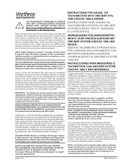
STEP 3. Program dip switches<br />
On the rear of the speedometer there is an oval shaped black plug (See Figure 3). Upon removal of the plug two six- position<br />
DIP switches will come into view. Also on the rear of the case is a blue label denoting the function of each switch position.<br />
The label is divided into two sections- Programming and Filter. Only the eight programming switches are used at this stage.<br />
The Divide number must be programmed into the speedometer in Binary Code Decimal format. That is, the TENS position and<br />
the ONES positions must be programmed separately.<br />
EXAMPLE: Assume a divide number of 41.<br />
41 = 40 (TENS divide number)<br />
1 (ONES divide number)<br />
First, program the1. Refer to the chart on Page 4 and move<br />
position 1 to ON and switch positions 2, 3, & 4 to OFF.<br />
Next, to program the 40, refer to the chart and move switch.<br />
position 7 to ON and switch position 5, 6 and 8 to OFF.<br />
When the Divide number is 9 or below, set all the TENS switches<br />
to OFF.<br />
FIGURE 3<br />
Filter dip switches<br />
To minimize any extraneous electrical noise from interfering<br />
with the operation of the speedometer <strong>Veethree</strong> has incorporated<br />
filter switches to fine tune the filter band to the applica tion. The filter programming is accomplished as follows:<br />
Find switch positions 9 through 12 on the DIP switch on the right. Refer to the chart labeled Filter Programming on Page 4.<br />
Find the range of full scale frequencies in the left hand column that covers the full scale frequency of the application. Read<br />
accross to the right and set switch positions 9 thru 12 as indicated.<br />
NOTE: For applications using a Drive Ratio adapter providing 1000 Revs at 60 MPH, the Full Scale Frequency will be 189 Hz.<br />
and the Divide number will be 8. The program DIP switches should be set with the TENS Divide numbers to the off position<br />
and the ONES Divide numbers set for 8. The Filter programming switches should be set for the 330-347 Full Scale Frequency<br />
positions.<br />
Replace the oval shaped black plug. The speedometer is now fully adjusted. The Programmable Speedometer can be used<br />
with pulse generator, magnetic proximity sensors without any additional adjustment. <strong>Veethree</strong> offers both senders for<br />
use with <strong>speedometers</strong>.<br />
SPEEDOMETER ACCURACY<br />
The speedometer accuracy is determined by the magnitude of the divide number and its nearness to a whole number. When<br />
the Divide number is a whole number (i.e. 42.00) the electronics error to the odometer and the vector movement is zero. This<br />
would mean the only other inherent error would be the accuracy of placing the pointer on its shaft. The worst situation would<br />
be to have a low Divide number resulting in a 0.5 fraction (i.e. 14.5). Since the program switches can only enter whole<br />
numbers the 0.5 needs to be rounded up or down. Fractional numbers closer to a whole number result in much better<br />
accuracy.<br />
Example# 1: 14.5 round to 15 .5/15 = 3.33% error<br />
Example# 2: 14.94 round to 15 .06/15 = 0.4% error<br />
The higher the divide number the more accurate the speedometer becomes.<br />
Example #3: 88.5 round to 89 .5/89 = .56% error<br />
Example #4: 88.13 round to 88 .13/89 = .147% error<br />
When designing an application using a magnetic proximity sensor it is very important to try to keep the Divide number as<br />
close to a whole number as possible. This will keep the system error to an absolute minimum. Whole number Divide numbers<br />
have no digital error.<br />
PAGE 3
EXAMPLE: Assume a DIVIDE number of 41.<br />
That is 1 ONES. Program switch positions 1 thru 4 next to the 1 in the ONES DIVIDE NUMBER column.<br />
That is also 40 TENS. Program switch positions 5 thru 8 next to the 40 in the TENS DIVIDE NUMBER column.<br />
PROGRAM CHART FILTER PROGRAM CHART<br />
Ones Tens Full<br />
Divide Switch Positions Divide Switch Positions Scale<br />
Switch Positions<br />
Number Number Frequency<br />
1 2 3 4 5 6 7 8 9 10 11 12<br />
1 ON OFF OFF OFF 10 ON OFF OFF OFF < 347 ON OFF OFF OFF<br />
2 OFF ON OFF OFF 20 OFF ON OFF OFF 347-388 ON OFF OFF ON<br />
3 ON ON OFF OFF 30 ON ON OFF OFF 389-546 ON OFF ON ON<br />
4 OFF OFF ON OFF 40 OFF OFF ON OFF 547-695 OFF OFF OFF OFF<br />
5 ON OFF ON OFF 50 ON OFF ON OFF 696-748 OFF OFF OFF ON<br />
6 OFF ON ON OFF 60 OFF ON ON OFF 749-808 OFF OFF ON OFF<br />
7 ON ON ON OFF 70 ON ON ON OFF 809-905 OFF OFF ON ON<br />
8 OFF OFF OFF ON 80 OFF OFF OFF ON 906-1072 ON ON ON OFF<br />
9 ON OFF OFF ON 90 ON OFF OFF ON 1073-1286 ON ON ON ON<br />
1287-1497 OFF ON OFF OFF<br />
1498-1771 OFF ON OFF ON<br />
1772-2145 OFF ON ON OFF<br />
> 2145 OFF ON ON ON<br />
Correction formula for <strong>programmable</strong> <strong>speedometers</strong><br />
To change or correct an existing speedometer reading to a different reading, the Program Divide Number<br />
is changed, using Switches 1 through 8 (See Figure above).<br />
Incorrect speed reading (MPH or Km/H) x Program Divide Number<br />
Divided by Actual Speed<br />
= Correct DIVIDE number.<br />
Example:<br />
If the speedometer reads 45 MPH at 55 MPH actual speed, and the switches are set for a Program Divide # of 65:<br />
45 x 65 = 53.18, rounded off to 53<br />
55<br />
In this case, the switch configuration changes from Program DIVIDE # of 65 (101001100101) to Program DIVIDE<br />
# of 53 (110010101111) where 0 = OFF, 1=ON.<br />
Filter switches 9-12 are listed in the chart above. Determine Full Scale Frequency with the new settings by multiplying the<br />
new Divide # x Constant 23.61.<br />
In the above example, 53 x 23.61 = 1,251.33. If Necessary, reset switches 9-12 to reflect the correct new<br />
Full Scale Frequency.<br />
PAGE 4