Installation and Operation Manual 307 Power ... - Midmark
Installation and Operation Manual 307 Power ... - Midmark
Installation and Operation Manual 307 Power ... - Midmark

You also want an ePaper? Increase the reach of your titles
YUMPU automatically turns print PDFs into web optimized ePapers that Google loves.
RETURN TO TABLE<br />
OF CONTENTS<br />
<strong>Installation</strong> <strong>and</strong><br />
<strong>Operation</strong> <strong>Manual</strong><br />
TABLE<br />
UP<br />
DOWN<br />
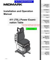
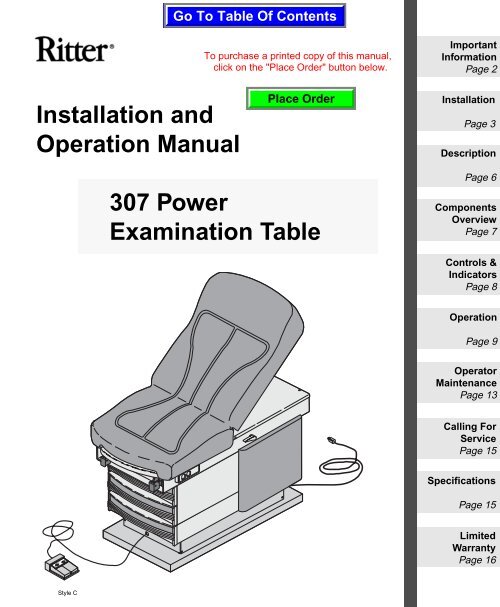
<strong>307</strong> <strong>Power</strong><br />
Examination Table<br />
Important<br />
Information<br />
Page 2<br />
<strong>Installation</strong><br />
Page 3<br />
Description<br />
Page 6<br />
Components<br />
Overview<br />
Page 7<br />
Controls &<br />
Indicators<br />
Page 8<br />
<strong>Operation</strong><br />
Page 9<br />
Operator<br />
Maintenance<br />
Page 13<br />
Calling For<br />
Service<br />
Page 15<br />
Specifications<br />
Page 15<br />
Limited<br />
Warranty<br />
Page 16
RETURN TO TABLE<br />
OF CONTENTS<br />
Owner’s Product Identification<br />
(information that you will need to provide for servicing - key information is highlighted)<br />
Date of Purchase Serial Number<br />
Name of Owner / Facility / Department<br />
Model Number<br />
Name of Authorized Ritter Dealer Telephone # of Authorized Ritter Dealer<br />
Address of Authorized Ritter Dealer<br />
MODEL AND SERIAL<br />
NUMBER LOCATION<br />
Ritter<br />
<strong>307</strong><br />
TABLE<br />
UP<br />
DOWN<br />
MA372000
RETURN TO TABLE TO HOME PAGE<br />
OF CONTENTS<br />
(or depress Alt <strong>and</strong> Tab keys)<br />
CONTENTS<br />
IMPORTANT INFORMATION .................................................................................................2<br />
Scope <strong>and</strong> Purpose of This <strong>Manual</strong> ...............................................................................2<br />
Intended Use of Product.................................................................................................2<br />
Safety Instructions ..........................................................................................................2<br />
Explanation of Safety Symbols <strong>and</strong> Notes......................................................................2<br />
INSTALLATION ......................................................................................................................3<br />
Unpacking.......................................................................................................................3<br />
Leveling The Table..........................................................................................................4<br />
Installing Paper Retaining Straps ...................................................................................4<br />
Installing Paper Roll Dowel Rod .....................................................................................5<br />
Electrical Requirements..................................................................................................5<br />
DESCRIPTION........................................................................................................................6<br />
Introduction.....................................................................................................................6<br />
Features..........................................................................................................................6<br />
COMPONENTS OVERVIEW ..................................................................................................7<br />
CONTROLS AND INDICATORS ............................................................................................8<br />
OPERATION...........................................................................................................................9<br />
Back Section Positioning ................................................................................................9<br />
Table Top Height Positioning...........................................................................................9<br />
Stirrups .........................................................................................................................10<br />
Footrest.........................................................................................................................11<br />
Irrigation Pan ................................................................................................................11<br />
Paper Roll .....................................................................................................................12<br />
Pelvic Lift (Optional)......................................................................................................12<br />
Drawer Heater (Optional)..............................................................................................13<br />
List of Authorized Accessories......................................................................................13<br />
Patient Positioning ........................................................................................................13<br />
OPERATOR MAINTENANCE...............................................................................................13<br />
Preventive Maintenance ...............................................................................................13<br />
Cleaning .......................................................................................................................14<br />
CALLING FOR SERVICE.....................................................................................................15<br />
SPECIFICATIONS ................................................................................................................15<br />
LIMITED WARRANTY ..........................................................................................................16
Important<br />
Information<br />
2<br />
RETURN TO TABLE<br />
OF CONTENTS<br />
IMPORTANT INFORMATION<br />
Scope <strong>and</strong> Purpose of This <strong>Manual</strong><br />
This manual covers complete instructions for the installation, operation, <strong>and</strong> normal<br />
care of the Model <strong>307</strong> <strong>Power</strong> Examination Table. It is intended that this<br />
manual be used by any medical personnel responsible for operating the examination<br />
table during a medical procedure or performing operator level maintenance.<br />
Intended Use of Product<br />
This product is intended for use in examination / procedure enviroments where<br />
patient positioning is required to accomplish general medical examinations <strong>and</strong> /<br />
or procedures.<br />
Safety Instructions<br />
The primary concern of <strong>Midmark</strong> is that this equipment is operated <strong>and</strong> maintained<br />
with the safety of the patient <strong>and</strong> staff in mind. To assure safer <strong>and</strong> more<br />
reliable operation:<br />
• Read <strong>and</strong> underst<strong>and</strong> this manual before attempting to install or operate the<br />
table.<br />
• Assure that appropriate personnel are informed on the contents of this manual;<br />
this is the responsibility of the purchaser.<br />
• Assure that this manual is located near the table, or if possible, permanently<br />
affixed to the table.<br />
Explanation of Safety Symbols <strong>and</strong> Notes<br />
DANGER<br />
Indicates an imminently hazardous situation which, if not<br />
avoided, will result in death or serious injury. The DANGER<br />
symbol is limited to the most extreme situations.<br />
WARNING<br />
Indicates a potentially hazardous situation which, if not<br />
avoided, could result in death or serious injury.
RETURN TO TABLE<br />
OF CONTENTS<br />
CAUTION<br />
Indicates a potentially hazardous situation which, if not avoided,<br />
may result in minor or moderate injury. It may also be used to<br />
alert against unsafe practices.<br />
EQUIPMENT ALERT<br />
Indicates an imminently or potentially hazardous situation which,<br />
if not avoided, will or may result in serious, moderate, or minor<br />
equipment damage.<br />
NOTE<br />
Amplifies an operating procedure, practice, or condition.<br />
INSTALLATION<br />
Unpacking<br />
EQUIPMENT ALERT<br />
To avoid damaging the table’s upholstered top or side panels, do<br />
not use a knife or other sharp object to open the table’s packaging.<br />
Also, to avoid damaging the table, do not lift at points (2, Figure 2).<br />
Carefully remove the packaging from the table <strong>and</strong> foot control, <strong>and</strong> then inspect<br />
the table for any shipping damage. Report any damage to the shipping company<br />
<strong>and</strong> fill out a concealed damage report.<br />
Unbolt the table from the wooden shipping skid by removing four bolts (1, Figure<br />
2) from the underside of the table’s base.<br />
WARNING<br />
The table weighs approximately 390 lbs (176.9 kgs). Get an<br />
assistant to help remove the table from the shipping skid.<br />
Also, use proper lifting techniques when lifting table. Failure to do so<br />
could result in serious back injury.<br />
After unbolting, remove the table from the shipping skid (3), lifting at points (4<br />
<strong>and</strong> 5). Do not lift at points (2); these are unsupported areas. Position the table<br />
in room as desired.<br />
Remove red tape from stirrups. Pull out foot extension (6) <strong>and</strong> remove red<br />
packing tape from the foot extension components. Return foot extension to its<br />
stowed position.<br />
Important<br />
Information<br />
<strong>Installation</strong><br />
3
<strong>Installation</strong><br />
4<br />
2<br />
10<br />
3<br />
4<br />
Leveling The Table<br />
1<br />
8<br />
RETURN TO TABLE<br />
OF CONTENTS<br />
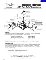
Figure 2. Table <strong>Installation</strong><br />
A leveling screw pad (7, Figure 2) is located under each corner of the table’s<br />
base. Adjust the four leveling screw pads (7) up or down (by turning them) until<br />
a solid, level installation is achieved.<br />
Installing Paper Retaining Straps<br />
13<br />
9<br />
MA372100<br />
NOTE<br />
The retaining straps may have to be stretched in order for them to be installed.<br />
The material will recover, becoming taut again after installation.<br />
12<br />
Ritter<br />
<strong>307</strong><br />
13<br />
13<br />
TABLE<br />
UP<br />
DOWN<br />
2<br />
8<br />
6<br />
11<br />
5<br />
12<br />
7<br />
13<br />
2
RETURN TO TABLE<br />
OF CONTENTS<br />
Two retaining straps are shipped in a drawer with the dowel rod. Install one retaining<br />
strap (8, Figure 2) on two snaps (9) <strong>and</strong> the other retaining strap (8) on<br />
two snaps (10).<br />
Installing Paper Roll Dowel Rod<br />
A wood dowel rod (11, Figure 2) for supporting a paper roll (12) is shipped in<br />
one of the drawers. To install the dowel rod on a table with a styled upholstery<br />
top, slide the dowel rod (11) through the paper roll (12) (up to an 18 in. x<br />
3.5 in. [45.7 cm to 8.9 cm] diameter paper roll) <strong>and</strong> then insert one end of the<br />
dowel rod in one of the sockets (13), located on the rear side of the table’s back<br />
section. Slide the end of the dowel rod back into the enlongated hole of the<br />
socket (13) as far as possible <strong>and</strong> then push the dowel rod into the hole until the<br />
other end of the dowel rod can be inserted into the other socket (13). Center the<br />
dowel rod (11) <strong>and</strong> pull it forward to the front of the sockets. To install the dowel<br />
rod on a table with a cut & sewn upholstery top, slide the dowel rod (11)<br />
through the paper roll (12) (up to an 21 in. x 3.5 in. [53.3 cm to 8.9 cm] diameter<br />
paper roll) <strong>and</strong> then place the dowel rod ends in the two dowel rod sockets (13),<br />
located on the rear side of the table’s back section.<br />
Electrical Requirements<br />
WARNING<br />
All exposed metal parts of the table are electrically grounded.<br />
When performing a cauterization or similar treatment,<br />
the patient must be insulated from the metal portions of the table by<br />
nonconductive material. Failure to do so could result in electrical<br />
shock or burns to the patient.<br />
Use 115 VAC, 60 HZ alternating current only. Failure to do so could result<br />
in electrical shock to personnel <strong>and</strong> will result in damage to table.<br />
The electrical rating for the Model <strong>307</strong> <strong>Power</strong> Examination Table without an optional<br />
drawer heater is 115 VAC, 60 Hz, 11.5 amps. The electrical rating for the<br />
Model <strong>307</strong> <strong>Power</strong> Examination Table with an optional drawer heater is 115 VAC,<br />
60 Hz, 12 amps. The three-pronged grounding plug on the table power cord<br />
must be plugged into a matching three-pronged, grounded, non-isolated, correctly<br />
polarized 115 VAC receptacle. The single table power cord provides power<br />
for all electrical functions of the table, including the duplex receptacle <strong>and</strong> the<br />
optional drawer heater (if purchased).<br />
<strong>Installation</strong><br />
5
Description<br />
6<br />
DESCRIPTION<br />
Introduction<br />
RETURN TO TABLE<br />
OF CONTENTS<br />
The <strong>307</strong> <strong>Power</strong> Examination Table is used in examination rooms for general examinations<br />
<strong>and</strong> procedures. The height of the table top is easily adjustable by<br />
operation of a foot control pedal. Also, the angle of the back section is easily<br />
adjustable by operation of a spring assisted release h<strong>and</strong>le. A hydraulic unit is<br />
used to provide the necessary power to adjust the table height. The seat section<br />
normally rests in a horizontal position, but can be tilted up +5° when supported<br />
with an optional pelvic lift bar, achieving the lithotomy position. There are<br />
two storage drawers <strong>and</strong> a bulk storage area which accommodate supplies used<br />
during examinations. There are many other features which are listed below:<br />
Features<br />
The Model <strong>307</strong> Examination Table has . . .<br />
• an manually adjustable back section which is controlled by a spring assisted<br />
release h<strong>and</strong>le, located on both the left <strong>and</strong> right sides of the table. The<br />
back section is adjustable from a full horizontal table position (0°) to a chair<br />
position (+65°).<br />
• an adjustable table top height which is controlled by a foot control pedal.<br />
The table top height is adjustable from a 27 in. (68.6 cm) minimum to a 37.5<br />
in. (95.2 cm) maximum height <strong>and</strong> is powered by a hydraulic power unit<br />
which supplies hydraulic power to provide movement for the table top height.<br />
• an optional pelvic lift bar which allows the seat section to be positioned in the<br />
Lithotomy position.<br />
• an extendable footrest shelf which includes a positionable upholstered pad<br />
<strong>and</strong> a removable treatment pan.<br />
• right <strong>and</strong> left stirrups which can be extended to an infinite number of positions<br />
as well as laterally in four positions.<br />
• two storage drawers on steel ball bearing glides which are located on the<br />
foot end of the table <strong>and</strong> a bulk storage area accessed through two hinged<br />
doors which are located on both the rear right <strong>and</strong> left sides of the table.<br />
• styled drawer fronts which have molded h<strong>and</strong> pulls <strong>and</strong> come with snap-in<br />
(tool-less) epoxy painted color steel inserts.<br />
• an optional drawer warmer which warms the foot end, top drawer.<br />
• a duplex, hospital grade 115 VAC receptacle, located on the foot end, left<br />
side of the table.<br />
• a styled, seamless upholstery top or a cut & sewn upholstery top.<br />
• a paper roll holder which is hidden in the head end of the upholstered top<br />
<strong>and</strong> tear strips, located at the foot end <strong>and</strong> head end of the upholstered top,<br />
to secure examination paper during a patient examination or procedure.
COMPONENTS OVERVIEW<br />
RETURN TO TABLE<br />
OF CONTENTS<br />
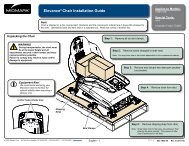
The illustration below (Figure 3) shows the location of the table’s major components<br />
<strong>and</strong> the chart below provides their descriptive name.<br />
6<br />
5<br />
3<br />
13<br />
4<br />
2<br />
11<br />
TABLE<br />
DOWN<br />
UP<br />
9<br />
1<br />
15<br />
Figure 3. Components Overview<br />
MA372200<br />
DESCRIPTION OF COMPONENTS<br />
1. Back Section (adjustable angle) 9. Pelvic Lift Bar (optional)<br />
2. Seat Section (adjustable height) 10. Duplex Receptacle<br />
3. Foot Rest Shelf (extendable) 11. Drawer Warmer (optional)<br />
4. Footrest Pad (removable) 12. Paper Roll Dowel<br />
5. Treatment Irrigation Pan 13. Foot Control<br />
6. Stirrups 14. Release H<strong>and</strong>le<br />
7. Storage Drawers (two)<br />
8. Bulk Storage Doors<br />
15. Decorative Panel<br />
7<br />
10<br />
12<br />
14<br />
8<br />
Description<br />
Components<br />
Overview<br />
7
Controls &<br />
Indicators<br />
8<br />
RETURN TO TABLE<br />
OF CONTENTS<br />
CONTROLS & INDICATORS<br />
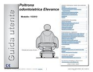
The illustration below (Figure 4) shows the location of the table’s controls <strong>and</strong> indicators<br />
<strong>and</strong> the chart below describes their function.<br />
6<br />
5<br />
Ref. Control Function<br />
1 TABLE UP pedal when depressed, raises the table top upward.<br />
2 TABLE DOWN pedal when depressed, lowers the table top downward.<br />
3 release h<strong>and</strong>le used to release the back section so it may be<br />
lowered.<br />
4 duplex receptacle provides power to small accessories used<br />
during an examination or procedure.<br />
5 heater on / off switch<br />
(optional equipment)<br />
6 pelvic lift support bar /<br />
release (optional equipment)<br />
TABLE<br />
UP<br />
DOWN<br />
1<br />
2<br />
Figure 4. Controls <strong>and</strong> Indicators<br />
4<br />
MA372300<br />
turns the drawer warmer heater on or off. The<br />
switch illuminates to indicate that the heater is<br />
operating.<br />
automatically supports seat section in pelvic<br />
lift position when seat section is raised. To<br />
release seat section, operator rotates pelvic<br />
lift support bar <strong>and</strong> lowers seat section.<br />
3
OPERATION<br />
RETURN TO TABLE<br />
OF CONTENTS<br />
WARNING<br />
Do not use this table in an explosive or oxygen-rich atmosphere.<br />
To do so could result in an explosion or fire.<br />
Back Section Positioning<br />
The back section can be<br />
positioned at any angle<br />
between horizontal (0°)<br />
<strong>and</strong> the chair position<br />
+65° ±5°. To raise the<br />
back section, simply lift<br />
the back section upward<br />
(1). To lower the back<br />
section, hold the back<br />
section while actuating<br />
the release h<strong>and</strong>le (3);<br />
then lower or push the<br />
back section down (2) to<br />
the desired position.<br />
Table Top Height Positioning<br />
1<br />
2<br />
65°<br />
3<br />
2<br />
1<br />
27"<br />
(68.6 CM)<br />
37.5"<br />
(95.2 CM)<br />
1<br />
UP<br />
TABLE<br />
DOWN<br />
MA362400<br />
2<br />
MA372500<br />
Controls &<br />
Indicators<br />
<strong>Operation</strong><br />
9
<strong>Operation</strong><br />
10<br />
RETURN TO TABLE<br />
OF CONTENTS<br />
EQUIPMENT ALERT<br />
The table top will stop moving when either the Up or Down<br />
travel limit is reached, but the hydraulic motor will continue to run<br />
until the foot pedal is released. Do not continue to operate a function that has<br />
reached its limit; this will cause the hydraulic motor to overheat <strong>and</strong> may reduce<br />
the life of the motor.<br />
The table top can be positioned at any height between 27.0 in. (68.6 cm) minimum<br />
<strong>and</strong> 37.5 in. (95.2 cm) maximum. To adjust the table top upward, depress<br />
<strong>and</strong> hold the TABLE UP pedal (1) until the table top reaches the desired height<br />
or the maximum height is achieved. To lower the table top downward, depress<br />
<strong>and</strong> hold the TABLE DOWN pedal (2) until the table top reaches the desired<br />
height or the minimum height is achieved.<br />
Stirrups<br />
To erect the stirrup, grasp end of stirrup <strong>and</strong> pull stirrup straight out of table to<br />
full extension. Unfold stirrup upward to an erect position.<br />
NOTE<br />
If you are applying any downward pressure on the end of the stirrup when<br />
sliding it in or out, it may be very difficult to move. This is normal <strong>and</strong> is part<br />
of the stirrup extension locking mechanism. For ease of movement, lift up<br />
slightly while sliding the stirrup in or out.<br />
To adjust the stirrup extension<br />
length, hold the end of the stirrup<br />
<strong>and</strong> slide in or out until the desired<br />
extension is achieved.<br />
WARNING<br />
Failure to engage<br />
the lateral locking<br />
mechanism could allow patient<br />
to lose balance resulting<br />
in personal injury to patient.<br />
To adjust the lateral position of a<br />
1<br />
stirrup, lift end of stirrup <strong>and</strong> then<br />
MA362100<br />
rotate stirrup to the right or left into one of the four possible lateral positions.<br />
The stirrup will click into each position as it is rotated. When the desired position<br />
is attained, lower stirrup to engage the lateral locking mechanism. Check<br />
that lateral locking mechanism is engaged by attempting to rotate stirrup assem-<br />
4<br />
3<br />
2
RETURN TO TABLE<br />
OF CONTENTS<br />
bly without lifting on stirrup end.<br />
To return stirrup to storage, grasp end of stirrup <strong>and</strong> pull stirrup straight out to<br />
full extension. Fold stirrup down against bar, rotate stirrup to lateral position 1,<br />
<strong>and</strong> then slide stirrup back into stowed position.<br />
Footrest<br />
To position the footrest (1), pull<br />
footrest out to the desired position.<br />
The upholstered pad (2)<br />
on the footrest will extend with<br />
the footrest.<br />
To remove the upholstered footrest<br />
pad (2) from the footrest<br />
(1), fully extend the footrest <strong>and</strong><br />
lift the upholstered pad straight<br />
up off the footrest.<br />
To replace the upholstered footrest<br />
pad (2), align pad glides (3)<br />
with slots (4) in footrest (1) <strong>and</strong><br />
install. Slide footrest into table.<br />
Irrigation Pan<br />
To expose the irrigation pan (1) for<br />
use, grasp the footrest (2) <strong>and</strong> pull<br />
until footrest is fully extended.<br />
Then, slide upholstered footrest<br />
pad (3) back into table. Now, grasp<br />
the footrest (2) again <strong>and</strong> slide the<br />
footrest in or out until the irrigation<br />
pan is positioned as desired.<br />
The irrigation pan (1) can easily be<br />
removed for cleaning when the footrest<br />
(2) is fully extended.<br />
3<br />
4<br />
1<br />
2<br />
2<br />
1<br />
3<br />
MA362200<br />
3<br />
MA362300<br />
<strong>Operation</strong><br />
11
<strong>Operation</strong><br />
12<br />
Paper Roll<br />
4<br />
3<br />
RETURN TO TABLE<br />
OF CONTENTS<br />
A wood dowel rod (1) for supporting a paper roll (2) is supplied with the table.<br />
To install the dowel rod on a table with a styled upholstery top, slide the<br />
dowel rod (1) through the paper roll (2) (up to an 18 in. x 3.5 in. [45.7 cm to 8.9<br />
cm] diameter paper roll) <strong>and</strong> then insert one end of the dowel rod in one of the<br />
sockets (3), located on the rear side of the table’s back section. Slide the end of<br />
the dowel rod back into the enlongated hole of the socket (3) as far as possible<br />
<strong>and</strong> then push the dowel rod into the hole until the other end of the dowel rod<br />
can be inserted into the other socket (3). Center the dowel rod (11) <strong>and</strong> pull it<br />
forward to the front of the sockets. Pull the paper over the table top <strong>and</strong> feed paper<br />
under two retaining straps (4). To install the dowel rod on a table with a<br />
cut <strong>and</strong> sewn upholstery top, slide the dowel rod (1) through the paper roll (2)<br />
(up to an 21 in. x 3.5 in. [53.3 cm to 8.9 cm] diameter paper roll) <strong>and</strong> then place<br />
the dowel rod ends in the two dowel rod sockets (3), located on the rear side of<br />
the table’s back section. Pull the paper over the table top <strong>and</strong> feed paper under<br />
two retaining straps (4).<br />
Pelvic Lift (Optional)<br />
To raise the seat section (1) to the Pelvic Lift<br />
Position, grasp the lower edge of the seat<br />
section <strong>and</strong> raise slightly until the springloaded<br />
pelvic lift support bar (2) snaps to its<br />
full upright <strong>and</strong> locked position. Lower the<br />
seat section onto the support bar.<br />
To lower the seat section (1) back to normal<br />
position, grasp the edge of the seat section<br />
<strong>and</strong> raise slightly; then rotate pelvic lift support<br />
bar (2) down by pulling on its h<strong>and</strong>le<br />
(3); then lower the seat section down.<br />
1<br />
2<br />
4<br />
3<br />
1<br />
2<br />
2<br />
1<br />
MA372600<br />
3<br />
MA362500
Drawer Heater (Optional)<br />
RETURN TO TABLE<br />
OF CONTENTS<br />
The drawer heater preheats the contents of<br />
the top drawer (1) on the foot end of the table<br />
to approximately body temperature.<br />
To operate the heater, turn the heater on/ off<br />
switch (2) to ON “I”. The switch will illuminate<br />
to indicate that the heater is operating.<br />
To turn the heater off, turn the heater on / off<br />
switch (2) to OFF “O”. The switch will stop illuminating,<br />
indicating that the heater is no<br />
longer operating.<br />
List of Authorized Accessories<br />
Listed below are the accessories which are authorized for use with the table.<br />
Accessory Name Order Number<br />
• Knee Crutch 9A0100X<br />
• Armboard 9A0200X<br />
• Procto Rest 9A0400X<br />
• Stainless Steel Pan 9A7000X<br />
• Urology Drain Pan 9A10400X<br />
• Pelvic Lift 9A10500X<br />
• Welch Allen Bracket 9A18000X<br />
• Knee Crutch 9A20600X<br />
• Side Rail 9A21000X<br />
Patient Positioning<br />
The table is designed to accommodate the following examination positions:<br />
• Full Flat Table Position<br />
• Chair Position<br />
• Lithotomy (Pelvic) Position<br />
OPERATOR MAINTENANCE<br />
Preventive Maintenance<br />
Little routine maintenance is required other than periodic inspection of the electrical<br />
cord, foot control cord, <strong>and</strong> hydraulic hoses to ensure they are free of cuts<br />
or damage, periodic inspection of the mechanical functions to ensure satisfacto-<br />
2<br />
1<br />
MA362600<br />
<strong>Operation</strong><br />
Operator<br />
Maintenance<br />
13
Operator<br />
Maintenance<br />
14<br />
RETURN TO TABLE<br />
OF CONTENTS<br />
ry operation, <strong>and</strong> periodic check of fasteners to ensure they are present <strong>and</strong><br />
tightened securely.<br />
Have your authorized dealer inspect your table every six months. Oil moving<br />
parts (such as back hinge, pelvic tilt points, <strong>and</strong> the stirrup indexing pivot) with a<br />
light machine oil to assure quiet, smooth, <strong>and</strong> dependable operation.<br />
Cleaning<br />
Upholstery<br />
EQUIPMENT ALERT<br />
The upholstery material that covers the top of the table is resistant<br />
to most medicinal-type stains, but may be damaged by solvents<br />
<strong>and</strong> dyes. Remove any fluids which are spilled on the upholstery immediately.<br />
Regular care should maintained by daily wiping with a damp cloth or sponge,<br />
<strong>and</strong> periodic cleaning with a mild soap <strong>and</strong> water solution.<br />
Painted Metal Surfaces<br />
Wipe all painted metal surfaces with a clean cloth at least once a week. Apply<br />
paste wax periodically to preserve the surface luster.<br />
Drawers<br />
To remove a drawer for cleaning, pull drawer straight out.<br />
Drawer Insert Panels<br />
Wipe all drawer insert panels with a clean cloth at least once a week. Apply<br />
paste wax periodically to preserve the surface luster. If necessary, the insert<br />
panels can easily be removed for cleaning by reaching up from behind <strong>and</strong><br />
pushing out on insert panel with index finger.<br />
Unpainted Metal Surfaces<br />
Wipe all unpainted metal surfaces with a clean cloth. Use petroleum jelly or other<br />
white lubricants on moving parts. Lubrication will allow free movement of<br />
sliding parts <strong>and</strong> reduce noise.
CALLING FOR SERVICE<br />
RETURN TO TABLE<br />
OF CONTENTS<br />
If you are having a problem or have a question, refer to the inside front cover of<br />
this manual <strong>and</strong> call your dealer. Make sure that you have the information that<br />
is highlighted on the inside front cover of this manual available. If you can’t resolve<br />
your question or problem with your dealer, call the following number:<br />
1-800-<strong>Midmark</strong> (1-800-643-6275)<br />
8:00 a.m until 5:00 p.m. (Eastern St<strong>and</strong>ard time in the U.S.)<br />
Monday thru Friday, except for st<strong>and</strong>ard U.S. holidays.<br />
SPECIFICATIONS<br />
Patient Weight (Maximum): .......... 325 lbs (147.4 kgs)<br />
Weight of Table:............................. 390 lbs (176.9 kgs)<br />
Back Section Adjustment:............ 0° to +65°<br />
Table Top Height Adjustment:...... 27.0 in. (minimum) to 37.5 in. (maximum)<br />
(68.6 cm to 95.2 cm)<br />
Dimensions:<br />
Upholstered top............................... 27.0 in. wide x 57.5 in. long<br />
(68.6 cm x 146.0 cm)<br />
With Footrest Extended................... 75.5 in. (191.8 cm)<br />
Base ................................................ 19.75 in. x 36.0 in. x 1.25 in. high<br />
(50.2 cm x 91.4 cm x 3.2 cm)<br />
Electrical Requirements:.............. 115 VAC nominal (126 VAC maximum - 110<br />
VAC minimum), 60 HZ, 11.5 amps (max.<br />
without heater) or 12.0 amps (max. with<br />
heater)<br />
Paper Roll:<br />
Styled (seamless) Upholstery: ........ Can accept a paper roll up to 18 in. x<br />
3.5 in. (45.7 cm x 8.9 cm)<br />
Cut & Sewn Upholstery:.................. Can accept a paper roll up to 21 in. x<br />
3.5 in. (53.3 cm x 8.9 cm)<br />
<strong>Power</strong> Cord: ................................... extends 72 in. (182.9 cm) (Minimum) from<br />
table. 12 AWG / 3 conductor, SJT grey<br />
jacketed junior hard service with hospital<br />
grade grounding type plug.<br />
Certifications:................................ U.L Listed Medical Equipment<br />
C.U.L. listed to CSA St<strong>and</strong>ard C22.2 #125<br />
(on units without heater only)<br />
ISO-9001 Certified<br />
Operator<br />
Maintenance<br />
Calling For<br />
Service<br />
Specifications<br />
15
Limited<br />
Warranty<br />
16<br />
LIMITED WARRANTY<br />
RETURN TO TABLE<br />
OF CONTENTS<br />
SCOPE OF WARRANTY<br />
<strong>Midmark</strong> Corporation (“<strong>Midmark</strong>”) warrants to the original purchaser its new Alternate<br />
Care products <strong>and</strong> components (except for components not warranted under<br />
“Exclusions”) manufactured by <strong>Midmark</strong> to be free from defects in material <strong>and</strong><br />
workmanship under normal use <strong>and</strong> service. <strong>Midmark</strong>’s obligation under this warranty<br />
is limited to the repair or replacement, at <strong>Midmark</strong>’s option, of the parts or the<br />
products the defects of which are reported to <strong>Midmark</strong> within the applicable warranty<br />
period <strong>and</strong> which, upon examination by <strong>Midmark</strong>, prove to be defective.<br />
APPLICABLE WARRANTY PERIOD<br />
The applicable warranty period, measured from the date of delivery to the original<br />
user, shall be one (1) year for all warranted products <strong>and</strong> components.<br />
EXCLUSIONS<br />
This warranty does not cover <strong>and</strong> <strong>Midmark</strong> shall not be liable for the following: (1)<br />
repairs <strong>and</strong> replacements because of misuse, abuse, negligence, alteration, accident,<br />
freight damage, or tampering; (2) products which are not installed, used, <strong>and</strong><br />
properly cleaned as required in the <strong>Midmark</strong> “<strong>Installation</strong>” <strong>and</strong> or “<strong>Installation</strong> / <strong>Operation</strong><br />
<strong>Manual</strong> for this applicable product. (3) products considered to be of a consumable<br />
nature; (4) accessories or parts not manufactured by <strong>Midmark</strong>; (5) charges by<br />
anyone for adjustments, repairs, replacement parts, installation, or other work performed<br />
upon or in connection with such products which is not expressly authorized<br />
in writing in advance by <strong>Midmark</strong>.<br />
EXCLUSIVE REMEDY<br />
<strong>Midmark</strong>’s only obligation under this warranty is the repair or replacement of defective<br />
parts. <strong>Midmark</strong> shall not be liable for any direct, special, indirect, incidental,<br />
exemplary, or consequential damages or delay, including, but not limited to, damages<br />
for loss of profits or loss of use.<br />
NO AUTHORIZATION<br />
No person or firm is authorized to create for <strong>Midmark</strong> any other obligation or liability<br />
in connection with the products.<br />
THIS WARRANTY IS MIDMARK’S ONLY WARRANTY AND IS IN LIEU OF ALL<br />
OTHER WARRANTIES, EXPRESS OR IMPLIED. MIDMARK MAKES NO<br />
IMPLIED WARRANTIES OF ANY KIND INCLUDING ANY WARRANTIES OF<br />
MERCHANTABILITY OR FITNESS FOR ANY PARTICULAR PURPOSE. THIS<br />
WARRANTY IS LIMITED TO THE REPAIR OR REPLACEMENT OF DEFECTIVE<br />
PARTS.<br />
SF-1487 REV. A1
NOTES:<br />
RETURN TO TABLE<br />
OF CONTENTS<br />
Limited<br />
Warranty<br />
17
RETURN TO TABLE<br />
OF CONTENTS<br />
<strong>Midmark</strong> Corporation, Versailles, Ohio 45380 U.S.A.<br />
937-526-3662 FAX: 937-526-5542<br />
© <strong>Midmark</strong> Corporation - 1997 003-0850-00 Rev. B (6/97)