100 (all) - Midmark
100 (all) - Midmark
100 (all) - Midmark

You also want an ePaper? Increase the reach of your titles
YUMPU automatically turns print PDFs into web optimized ePapers that Google loves.
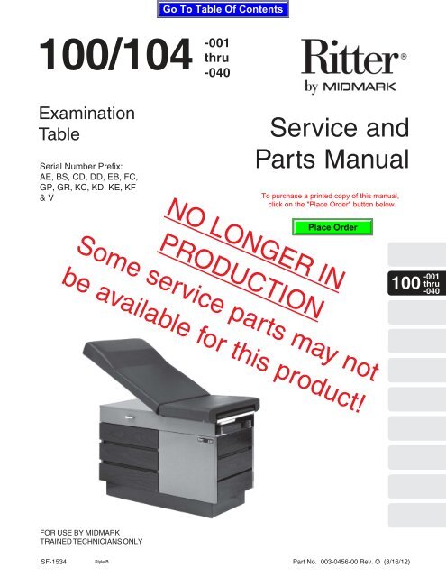
<strong>100</strong>/104<br />
Examination<br />
Table<br />
Serial Number Prefix:<br />
AE, BS, CD, DD, EB, FC,<br />
GP, GR, KC, KD, KE, KF<br />
& V<br />
FOR USE BY MIDMARK<br />
TRAINED TECHNICIANS ONLY<br />
-001<br />
thru<br />
-040<br />
Service and<br />
Parts Manual<br />
NO LONGER IN<br />
PRODUCTION<br />
Some service parts may not<br />
be available for this product!<br />
SF-1534 Part No. 003-0456-00 Rev. O (8/16/12)<br />
-001<br />
<strong>100</strong> thru<br />
-040
TABLE OF CONTENTS<br />
Section/Paragraph Page Section/Paragraph Page<br />
IMPORTANT INSTRUCTIONS<br />
General Safety Instructions......................................... ii<br />
Safety Alert Symbols ................................................... ii<br />
Warranty Instructions .................................................. ii<br />
SECTION I GENERAL INFORMATION<br />
1.1 Scope of Manual ......................................... 1-1<br />
1.2 Description of Model <strong>100</strong>/104 Tables .......... 1-1<br />
1.3 Standard Torque Specifications................... 1-1<br />
1.4 Table Specifications .................................... 1-1<br />
1.5 Parts Replacement Ordering ....................... 1-2<br />
1.6 Special Tools .............................................. 1-2<br />
SECTION II TESTING AND TROUBLESHOOTING<br />
Not Available<br />
SECTION III SCHEDULED MAINTENANCE<br />
Not Available<br />
SECTION IV MAINTENANCE/SERVICE<br />
INSTRUCTIONS<br />
Not Available<br />
SECTION V SCHEMATICS AND DIAGRAMS<br />
5.1 Electrical Schematics / Wiring Diagrams ..... 5-1<br />
SECTION VI PARTS LIST<br />
6.1 Introduction ................................................. 6-1<br />
6.2 Description of Columns ............................... 6-1<br />
Pictorial Index (<strong>100</strong>-001/004) ....................... 6-2<br />
Pictorial Index (<strong>100</strong>-005/008) .................... 6-2.1<br />
Pictorial Index (<strong>100</strong>-009/012) .................... 6-2.2<br />
Pictorial Index (<strong>100</strong>-013/014) .................... 6-2.3<br />
Pictorial Index (<strong>100</strong>-015/018) .................... 6-2.4<br />
Pictorial Index (<strong>100</strong>-019/022) .................... 6-2.5<br />
Pictorial Index (<strong>100</strong>-023/024) .................... 6-2.6<br />
Pictorial Index (<strong>100</strong>-025/026) .................... 6-2.7<br />
Pictorial Index (<strong>100</strong>-027/028) .................... 6-2.8<br />
Pictorial Index (<strong>100</strong>-029/030) .................... 6-2.9<br />
Pictorial Index (<strong>100</strong>-031/032) .................. 6-2.10<br />
Pictorial Index (<strong>100</strong>-033/034) .................. 6-2.11<br />
Pictorial Index (<strong>100</strong>-035/036) .................. 6-2.12<br />
Pictorial Index (<strong>100</strong>-037/038) .................. 6-2.13<br />
Pictorial Index (<strong>100</strong>-039/040) .................. 6-2.14<br />
Table Top Components (Standard) ............ 6-3.*<br />
Table Top Components (Soft Touch) ......... 6-4.*<br />
Upper Wrap Components ........................... 6-5.*<br />
Pelvic Tilt Assembly .................................... 6-6<br />
Stirrup Assembly ....................................... 6-7.*<br />
Cabinet Components ................................. 6-8.*<br />
Drawer Assembly ....................................... 6-9.*<br />
Step Assembly. ....................................... 6-10.*<br />
Electrical Components. ............................ 6-11.*<br />
COMMENTS ............................................................ 7-1<br />
FAX ORDERING FORM .......................................... 7-2<br />
(*) Indicates that there has been a serial number break for the illustration<br />
and that there are additional point page(s) following the original page.<br />
© <strong>Midmark</strong> 1997 SF-1534 Rev. 7/07 Page i Printed in U.S.A.
General Safety Instructions<br />
Safety First: The primary concern of <strong>Midmark</strong><br />
Corporation is that this table is maintained with the<br />
safety of the patient and staff in mind. To assure that<br />
services and repairs are completed safely and correctly,<br />
proceed as follows:<br />
(1) Read this entire manual before performing any<br />
services or repairs on this table.<br />
(2) Be sure you understand the instructions<br />
contained in this manual before attempting to<br />
service or repair this table.<br />
Safety Alert Symbols<br />
Throughout this manual are safety alert symbols that<br />
c<strong>all</strong> attention to particular procedures. These items are<br />
used as follows:<br />
DANGER<br />
A DANGER is used for an imminently<br />
hazardous operating procedure,<br />
practice, or condition which, if not correctly<br />
followed, will result in loss of life or serious<br />
personal injury.<br />
WARNING<br />
A WARNING is used for a potenti<strong>all</strong>y<br />
hazardous operating procedure,<br />
practice, or condition which, if not correctly<br />
followed, could result in loss of life or serious<br />
personal injury.<br />
CAUTION<br />
A CAUTION is used for a potenti<strong>all</strong>y<br />
hazardous operating procedure, practice,<br />
or condition which, if not correctly followed, could<br />
result in minor or moderate injury. It may also be<br />
used to alert against unsafe practices.<br />
EQUIPMENT ALERT<br />
An EQUIPMENT ALERT is used for an<br />
imminently or potenti<strong>all</strong>y hazardous<br />
operating procedure, practice, or condition which, if<br />
not correctly followed, will or could result in serious,<br />
moderate, or minor damage to unit.<br />
IMPORTANT INSTRUCTIONS<br />
NOTE<br />
A NOTE is used to amplify an operating procedure,<br />
practice or condition.<br />
Warranty Instructions<br />
Refer to the <strong>Midmark</strong> “Limited Warranty” printed in the<br />
Inst<strong>all</strong>ation and Operation Manual for warranty information.<br />
Failure to follow the guidelines listed below will<br />
void the warranty and/or render the <strong>100</strong> Examination<br />
Table unsafe for operation.<br />
• In the event of a malfunction, do not attempt to<br />
operate the table until necessary repairs have been<br />
made.<br />
• Do not attempt to disassemble table, replace malfunctioning<br />
or damaged components, or perform<br />
adjustments unless you are one of <strong>Midmark</strong>’s<br />
authorized service technicians.<br />
• Do not substitute parts of another manufacturer<br />
when replacing inoperative or damaged components.<br />
Use only <strong>Midmark</strong> replacement parts.<br />
© <strong>Midmark</strong> 1992 SF-1343 Page ii Printed in U.S.A.
1.1 Scope of Manual<br />
This manual contains detailed troubleshooting, scheduled<br />
maintenance, and service instructions for Model<br />
<strong>100</strong>/104 Medical Examination Table. This manual is<br />
intended to be used by <strong>Midmark</strong>’s authorized service<br />
technicians.<br />
1.2 Description Of Model <strong>100</strong>/104 Medical<br />
Examination Table.<br />
The Model <strong>100</strong>/104 Series Medical Examination Table is<br />
primarily used in examination rooms for general examinations<br />
and minor procedures. The table top is adjustable<br />
from a full horizontal position to a chair position.<br />
Also, when supported with an optional pelvic lift bar, the<br />
lithotomy position can be achieved. There are five<br />
storage drawers which accommodate supplies used<br />
during examinations.<br />
The major serviceable components of the table are the<br />
drawer heater plate (optional), heater on/off switch<br />
(optional), electrical receptacle, back lock assembly,<br />
lift assembly, step assembly, and two stirrup assemblies.<br />
Electrical Power:<br />
115 VAC line voltage is supplied thru the power cord to<br />
electrical receptacles located on the side of the table.<br />
As long as the power cord is plug into a supply outlet<br />
115 VAC power will be present at the receptacles.<br />
Optional Heater Plate:<br />
Some units are equipped with the optional heater plate<br />
for drawer warming. When the operator turns the (N.O.)<br />
Heater On/Off Switch to ON, closing the circuit, power is<br />
supplied to the 60 watt heater plate, heating the unit.<br />
This provides heat in the top, foot end drawer to warm<br />
instruments.<br />
1.3 Standard Torque Specifications<br />
The following standard torque specifications in Table<br />
1-1 apply to the various hardware used on the units<br />
unless otherwise listed elsewhere in service procedures<br />
or parts illustrations:<br />
SECTION I<br />
GENERAL INFORMATION<br />
SECTION I<br />
GENERAL INFORMATION<br />
Table 1-1. Torque Specifications<br />
Hardware Size Torque Values<br />
#6 ........................... 11 to 21 inch / lbs. (1.2 to 2.3 N•M)<br />
#8 ........................... 20 to 30 inch / lbs. (2.2 to 3.3 N M)<br />
#10.......................... 32 to 42 inch / lbs. (3.6 to 4.8 N M)<br />
1/4" ......................... 75 to 85 inch / lbs. (8.5 to 9.6 N M)<br />
5/16" .................... 18 to 22 foot / lbs. (24.4 to 29.8 N M)<br />
3/8" ...................... 31 to 35 foot / lbs. (42.0 to 47.5 N M)<br />
1/2" ...................... 50 to 60 foot / lbs. (67.8 to 81.4 N M)<br />
1.4 Table Specifications<br />
Description Data<br />
Weight:<br />
Weight of Table (without packaging) ....................... 250 lbs<br />
Capacity:<br />
Weight Capacity (Maximum) .................................... 325 lbs<br />
Dimensions :<br />
Height ..................................................................... 31.75 in.<br />
Base ...................................... 17.5" W. x 42.75" L. x 4.12 T.<br />
Step ..................................... 10.5" D. x 17.75" W. x 10.25 T.<br />
Paper Roll ..................................................... 3.5" Dia. x 21"<br />
Table Top Length (footrest extended) ..................... 72.5 in.<br />
Table Top Width ............................................................ 27 in.<br />
Over<strong>all</strong> Width ............................................................... 27 in.<br />
Seat Height (to top of upholstered<br />
seat at foot end) ................................................... 31.75 in.<br />
Table Adjustment:<br />
Back Section .................................................. 0 to 70 o (± 5 o )<br />
(manu<strong>all</strong>y adjusted, spring assisted)<br />
Back Lock Slippage Rating .......................................200 lbs<br />
(applied at head end of table)<br />
Stirrup ................................................4 position (L.H. & R.H.<br />
infinite extension ajustability<br />
Electrical Rating:<br />
Electrical Receptacle) ..................... Duplex Hospital Grade<br />
Power Consumption: ..................................... 115 VAC Unit<br />
(126 VAC maximum-110 VAC<br />
minimum), 60 HZ, 6 amps (max.<br />
without heater) or 6.5 amps (max.<br />
with heater) 60 watt heater rating.<br />
Recommended Circuit:<br />
A separate (dedicated) circuit is recommended for this table<br />
table. The table should not be connected to an electrical<br />
circuit with other appliances or equipment unless the circuit<br />
is rated for the additional load.<br />
© <strong>Midmark</strong> Corporation 1997 SF-1534 Page 1-1 Printed in U.S.A.
SECTION I<br />
GENERAL INFORMATION<br />
1.5 Parts Replacement Ordering<br />
If a part replacement is required, order the part directly<br />
from the factory as follows:<br />
NOTE<br />
It is important that the entire Model and Serial<br />
Number be presented when ordering parts, scheduling<br />
a service c<strong>all</strong> or seeking technical advice.<br />
(1) Location the serial number label on the rear of<br />
the back section and determine the model<br />
number and serial number of the table and<br />
record this data.<br />
(2) Refer to the Parts List to determine the item<br />
numbers of the parts, part numbers of the parts,<br />
descriptions of the parts, and quantities of parts<br />
needed and record this data (Refer to para 6.1).<br />
Description of Special Tool<br />
Manufacturer's<br />
Name / Address / Phone<br />
Table 1-2. Special Tool List<br />
NOTE<br />
Ask the Purchasing Department of the company that<br />
owns the table for this information. Otherwise, this<br />
information may be obtained from the dealer that sold<br />
the table.<br />
(3) Determine the inst<strong>all</strong>ation date of the table and<br />
record this data.<br />
(4) C<strong>all</strong> <strong>Midmark</strong> with the recorded information and<br />
ask for the Medical Products Technical Services<br />
Department. See back cover of this<br />
manual for the phone number or use the Fax<br />
Order Form (See page 7-2 for Fax Order Form).<br />
1.6 Special Tools<br />
Table 1-2 lists <strong>all</strong> of the special tools needed to repair<br />
the table, how to obtain the special tools, and the<br />
purpose of each special tool.<br />
Manufacturer's<br />
Part Number<br />
Purpose of Special Tool<br />
Multimeter Commerci<strong>all</strong>y Available Any Type Used to perform continuity and voltage checks.<br />
Pop Rivet Gun Commerci<strong>all</strong>y Available For inst<strong>all</strong>ation of 1/8 in.<br />
pop rivets.<br />
For inst<strong>all</strong>ation of drawer slides and mullions.<br />
Torque Wrench Commerci<strong>all</strong>y Available Any Type Used to tighten nuts or screws to specified values.<br />
© <strong>Midmark</strong> Corporation 1997 SF-1534 Page 1-2 Printed in U.S.A.
5.1 Electrical Schematics / Wiring<br />
Diagrams<br />
UNIT WITHOUT HEATER<br />
SECTION V<br />
SCHEMATICS AND DIAGRAMS<br />
120 V.A.C. 12 AMP.<br />
60 HZ. SUPPLY<br />
(MUST BE GROUNDED)<br />
UNIT WITH OPTIONAL HEATER (OFF)<br />
GREEN<br />
120 V.A.C. 12 AMP.<br />
60 HZ. SUPPLY<br />
(MUST BE GROUNDED)<br />
WHITE<br />
BLACK<br />
015-0066-03<br />
015-0066-03<br />
GREEN<br />
WHITE<br />
BLACK<br />
DUPLEX RECEPTACLE<br />
UNIT WITH OPTIONAL HEATER (ON)<br />
GREEN<br />
120 V.A.C. 12 AMP.<br />
60 HZ. SUPPLY<br />
(MUST BE GROUNDED)<br />
WHITE<br />
BLACK<br />
015-0066-03<br />
DUPLEX RECEPTACLE<br />
GREEN<br />
015-0141-00<br />
GREEN<br />
015-0141-00<br />
SECTION V<br />
SCHEMATICS AND DIAGRAMS<br />
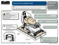
Figure 5-1 and 5-2 illustrate the current flow and wiring<br />
connections between the electrical components in the<br />
115 VAC table.<br />
DUPLEX RECEPTACLE<br />
WHITE<br />
015-0064-02<br />
BLACK<br />
015-0064-03<br />
MA492500<br />
Figure 5-1. 115 VAC Units Electrical Schematic / Wiring Diagram<br />
(Used on units with Serial Numbers AE<strong>100</strong>0 thru present, BS<strong>100</strong>0 thru BS8279 and CD<strong>100</strong>0 thru CD1827 )<br />
© <strong>Midmark</strong> Corporation 1997 SF-1534 Page 5-1 Printed in U.S.A.<br />
GREEN<br />
015-0141-00<br />
WHITE<br />
WHITE<br />
HEATER SWITCH<br />
(IN "OFF" POSITION)<br />
WHITE<br />
015-0064-02<br />
BLACK<br />
015-0064-03<br />
A B<br />
A B<br />
WHITE<br />
WHITE<br />
ILLUMINATED<br />
HEATER SWITCH<br />
(IN "ON" POSITION)<br />
60 WATT<br />
HEATER<br />
60 WATT<br />
HEATER
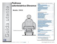
SECTION V<br />
SCHEMATICS AND DIAGRAMS<br />
UNIT WITH HEATER<br />
GREEN<br />
115 VAC, 12 AMP<br />
60 HZ Supply<br />
(MUST BE GROUNDED)<br />
120 VAC UNITS<br />
WITHOUT<br />
DRAWER HEATERS<br />
UNIT WITHOUT HEATER<br />
BLACK<br />
WHITE<br />
DUPLEX RECEPTACLE<br />
015-0066-03<br />
GREEN<br />
015-0141-00<br />
115 VAC, 12 AMP<br />
60 HZ Supply<br />
(MUST BE GROUNDED)<br />
BLACK<br />
015-0064-03<br />
4 5 WHITE<br />
WHITE 1<br />
WHITE<br />
015-0064-02<br />
2<br />
ILLUMINATED<br />
HEATER SWITCH<br />
(IN "ON" POSITION)<br />
60 WATT<br />
Heater is ON<br />
Figure 5-2. 115 VAC Units Electrical Schematic / Wiring Diagram<br />
(Used on units with Serial Numbers BS8279, CD1827, EB<strong>100</strong>0, FC<strong>100</strong>0, GP<strong>100</strong>0, GR<strong>100</strong>0, KC<strong>100</strong>0, KD<strong>100</strong>0,<br />
KE<strong>100</strong>0, KF<strong>100</strong>0 and V2200 thru present)<br />
© <strong>Midmark</strong> Corporation 1997 SF-1534 Rev 2/05 Page 5-2 Printed in U.S.A.<br />
BLACK<br />
WHITE<br />
015-0066-03<br />
GREEN<br />
BLACK<br />
WHITE<br />
120 VAC UNITS<br />
WITH<br />
DRAWER HEATERS<br />
Duplex<br />
Receptacle<br />
GREEN<br />
015-0141-00
6.1 Introduction<br />
The illustrated parts list provides information for<br />
identifying and ordering the parts necessary to maintain<br />
the unit in peak operating condition. Refer to paragraph<br />
1.5 for parts ordering information.<br />
The parts list also illustrates disassembly and assembly<br />
relationships of parts.<br />
6.2 Description of Columns<br />
The Item column of the parts list gives a component its<br />
own unique number. The same number is given to the<br />
component in the parts illustration. This <strong>all</strong>ows a part<br />
number of a component to be found if the technician<br />
can visu<strong>all</strong>y spot the part on the illustration. The<br />
technician simply finds the component in question on<br />
the illustration and notes the item number of that<br />
component. Then, he finds that item number in the<br />
parts list. The row corresponding to the item number<br />
gives the technician the part number, a description of<br />
the component, and quantity of parts per subassembly.<br />
Also, if a part number is known, the location of that<br />
component can be determined by looking for the item<br />
number of the component on the illustration.<br />
SECTION VI<br />
PARTS LIST<br />
SECTION VI<br />
PARTS LIST<br />
The Part No. column lists the MIDMARK part number<br />
for that component.<br />
The Description column provides a physical description<br />
of the component.<br />
The Qty. column lists the number of units of a particular<br />
component that is required for the subassembly. The<br />
letters “AR” denote “as required” when quantities of a<br />
particular component cannot be determined, such as:<br />
adhesive.<br />
Bullets { • } in the Part No. column and the Description<br />
column show the indenture level of a component. If a<br />
component does not have a bullet, it is a main component<br />
of that illustration. If a component has a bullet, it<br />
is a subcomponent of the next component listed higher<br />
in the parts list than itself that does not have a bullet.<br />
Likewise, if a component has two bullets, it is a subcomponent<br />
of the next component listed higher in the<br />
parts list than itself that has only one bullet.<br />
© <strong>Midmark</strong> Corporation 1997 SF-1534 Page 6-1 Printed in U.S.A.
Pictorial Index<br />
3<br />
4<br />
6<br />
Item Part No. Description Page<br />
1<br />
7<br />
Units with Serial Number AE<strong>100</strong>0<br />
SECTION VI<br />
PARTS LIST<br />
Burnt Umber<br />
MA354701<br />
Item Part No. Description Page<br />
<strong>100</strong>-001 <strong>100</strong> Exam Table - R.H. {Burnt Umber} 5 Cabinet Components ........................ 6-8<br />
(Serial Number Prefix "AE") ............. 6-2<br />
Drawer Assembly .......................... 6-9<br />
<strong>100</strong>-002 <strong>100</strong> Exam Table - L.H. {Burnt Umber} 6 Step Assembly ............................. 6-10.*<br />
(Serial Number Prefix "AE" [Shown]) 6-2 7 Electrical Components ................... 6-11<br />
<strong>100</strong>-003 <strong>100</strong> Exam Table - R.H. w/ Pelvic Lift<br />
{Burnt Umber} (Serial Number Prefix<br />
OPTIONAL ACCESSORIES<br />
"AE") ................................................. 6-2 Refer to MEDICAL ACCESSORY BOOK {004-0096-00}<br />
<strong>100</strong>-004 <strong>100</strong> Exam Table - L.H. w/ Pelvic Lift<br />
{Burnt Umber} (Serial Number Prefix 8 9A0<strong>100</strong>6 Knee Crutch Set ............................. 9A01<br />
"AE") ................................................. 6-2 9 9A0200* Armboard Assembly ....................... 9A02<br />
1 • Table Top Comp. (Standard) ............ 6-3 10 9A04001 Procto Rest .................................... 9A04<br />
Table Top Comp. (Soft Touch) ......... 6-4 11 9A104001 Urology Drain Pan ........................ 9A104<br />
2 Upper Wrap Components ............... 6-5.* 12 9A180002 Welch Allyn Bracket ..................... 9A180<br />
3 Pelvic Lift Assembly ....................... 6-6<br />
4 Stirrup Components ....................... 6-7<br />
Always Specify Model & Serial Number<br />
© <strong>Midmark</strong> Corporation 1997 SF-1534 Rev. 9/04 Page 6-2 Printed in U.S.A.<br />
5<br />
2
Pictorial Index<br />
3<br />
5<br />
1<br />
Item Part No. Description Page<br />
6<br />
Units with Serial Number BS<strong>100</strong>0<br />
SECTION VI<br />
PARTS LIST<br />
MA354800<br />
Item Part No. Description Page<br />
<strong>100</strong>-005 <strong>100</strong> Exam Table - R.H. {Warm Grey}<br />
OPTIONAL ACCESSORIES<br />
(Serial Number Prefix "BS") ............ 6-2.1 Refer to MEDICAL ACCESSORY BOOK {004-0096-00}<br />
<strong>100</strong>-006 <strong>100</strong> Exam Table - L.H. {Warm Grey}<br />
(Serial Number Prefix "BS" [Shown]) 6-2.1 7 9A0<strong>100</strong>6 Knee Crutch Set<br />
<strong>100</strong>-007 <strong>100</strong> Exam Table - R.H. w/ Soft Touch<br />
(BS<strong>100</strong>0 thru BS8278) ................... 9A01<br />
Top {Warm Grey} (Serial Number Prefix 8 9A02003 Armboard Assembly ....................... 9A02<br />
"BS") ................................................. 62.1 9 9A04001 Procto Rest .................................... 9A04<br />
<strong>100</strong>-008 <strong>100</strong> Exam Table - L.H. w/ Soft Touch 10 9A70000 Stainless Steel Treatment Pan .... 6-27.*<br />
Top {Warm Grey} (Serial Number Prefix 11 9A104001 Urology Drain Pan ........................ 9A104<br />
"BS") ............................................... 6-2.1 12 9A105004 Pelvic Lift Assembly ..................... 9A105<br />
1 • Table Top Comp. (Standard) .......... 6-3.* 13 9A10800X Drawer Heater Assembly ............. 9A108<br />
Table Top Comp. (Soft Touch) ...... 6-4.1 14 9A180002 Welch Allyn Bracket ..................... 9A180<br />
2 Upper Wrap Components ............... 6-5.* 15 9A206002 Knee Crutch Set<br />
3 Stirrup Components ..................... 6-7.*<br />
(BS8279 thru Present) ................. 9A206<br />
4 Cabinet Components ...................... 6-8.*<br />
Drawer Assembly ........................ 6-9.*<br />
16 9A2<strong>100</strong>02 Side Rails ..................................... 9A210<br />
5 Step Assembly ............................. 6-10.*<br />
6 Electrical Components ................ 6-11.1<br />
Always Specify Model & Serial Number<br />
© <strong>Midmark</strong> Corporation 1997 SF-1534 Rev. 9/04 Page 6-2.1 Printed in U.S.A.<br />
4<br />
2<br />
Warm Grey
Pictorial Index<br />
3<br />
5<br />
Item Part No. Description Page<br />
1<br />
6<br />
Units with Serial Number CD<strong>100</strong>0<br />
SECTION VI<br />
PARTS LIST<br />
MA354800<br />
Item Part No. Description Page<br />
<strong>100</strong>-009 <strong>100</strong> Exam Table - R.H. w / Heater {Warm<br />
Grey} (Serial Number Prefix "CD") . 6-2.2<br />
OPTIONAL ACCESSORIES<br />
<strong>100</strong>-010 <strong>100</strong> Exam Table - L.H. w / Heater {Warm<br />
Grey} (Serial Number Prefix "CD"<br />
Refer to MEDICAL ACCESSORY BOOK {004-0096-00}<br />
[Shown]) .......................................... 6-2.2 7 9A0<strong>100</strong>6 Knee Crutch Set<br />
<strong>100</strong>-011 <strong>100</strong> Exam Table - R.H. w/ Soft Touch<br />
(CD<strong>100</strong>0 thru CD1826) .................. 9A01<br />
Top and Heater {Warm Grey} (Serial 8 9A02003 Armboard Assembly ....................... 9A02<br />
Number Prefix "CD") ....................... 6-2.2 9 9A04001 Procto Rest .................................... 9A04<br />
<strong>100</strong>-012 <strong>100</strong> Exam Table - L.H. w/ Soft Touch 10 9A70000 Stainless Steel Treatment Pan .... 6-27.*<br />
Top and Heater {Warm Grey} (Serial 11 9A104001 Urology Drain Pan ........................ 9A104<br />
Number Prefix "CD") ....................... 6-2.2 12 9A105004 Pelvic Lift Assembly ..................... 9A105<br />
1 • Table Top Comp. (Standard) .......... 6-3.* 13 9A10800X Drawer Heater Assembly ............. 9A108<br />
Table Top Comp. (Soft Touch) ...... 6-4.1 14 9A180002 Welch Allyn Bracket ..................... 9A180<br />
2 Upper Wrap Components ............... 6-5.* 15 9A206002 Knee Crutch Set<br />
3 Stirrup Components ..................... 6-7.*<br />
(CD1827 thru Present) ................. 9A206<br />
4 Cabinet Components ...................... 6-8.*<br />
Drawer Assembly ........................ 6-9.*<br />
16 9A2<strong>100</strong>02 Side Rails ..................................... 9A210<br />
5 Step Assembly ............................. 6-10.*<br />
6 Electrical Components ................ 6-11.1<br />
Always Specify Model & Serial Number<br />
© <strong>Midmark</strong> Corporation 1997 SF-1534 Rev. 9/04 Page 6-2.2 Printed in U.S.A.<br />
4<br />
2<br />
Warm Grey
Pictorial Index<br />
3<br />
5<br />
1<br />
Item Part No. Description Page<br />
<strong>100</strong>-013 <strong>100</strong> Exam Table - R.H. - 220 V. Export<br />
Unit {Warm Grey} (Serial Number<br />
Prefix "DD") ....................................... 6-5<br />
<strong>100</strong>-014 <strong>100</strong> Exam Table - L.H. - 220 V. Export<br />
Unit w/ {WarmGrey} (Serial Number<br />
Prefix "DD") ........................................ 6-5<br />
1 • Table Top Comp. (Standard) .......... 6-17<br />
2 Upper Wrap Components ............. 6-27.*<br />
3 Stirrup Components ................... 6-29.*<br />
4 Cabinet Components .................... 6-31.*<br />
Drawer Assembly ...................... 6-35.*<br />
5 Step Assembly ............................. 6-37.*<br />
6 Electrical Components ................... 6-39<br />
6<br />
Units with Serial Number DD<strong>100</strong>0<br />
SECTION VI<br />
PARTS LIST<br />
MA354800<br />
Item Part No. Description Page<br />
OPTIONAL ACCESSORIES<br />
Refer to MEDICAL ACCESSORY BOOK {004-0096-00}<br />
7 9A0<strong>100</strong>6 Knee Crutch Set<br />
(DD<strong>100</strong>0 thru DD<strong>100</strong>5) .................. 9A01<br />
8 9A02003 Armboard Assembly ....................... 9A02<br />
9 9A04001 Procto Rest .................................... 9A04<br />
10 9A70000 Stainless Steel Treatment Pan .... 6-27.*<br />
11 9A104001 Urology Drain Pan ........................ 9A104<br />
12 9A105004 Pelvic Lift Assembly ..................... 9A105<br />
13 9A10800X Drawer Heater Assembly ............. 9A108<br />
14 9A180002 Welch Allyn Bracket ..................... 9A180<br />
15 9A206002 Knee Crutch Set<br />
(DD<strong>100</strong>6 thru Present) ................. 9A206<br />
16 9A2<strong>100</strong>02 Side Rails ..................................... 9A210<br />
Always Specify Model & Serial Number<br />
© <strong>Midmark</strong> Corporation 1997 SF-1534 Rev. 11/99 Page 6-2.3 Printed in U.S.A.<br />
4<br />
2<br />
Warm Grey
Pictorial Index<br />
3<br />
5<br />
Item Part No. Description Page<br />
<strong>100</strong>-015 <strong>100</strong> Exam Table - R.H. {Burnt Umber}<br />
(Serial Number Prefix "BS") ............ 6-2.4<br />
<strong>100</strong>-016 <strong>100</strong> Exam Table - L.H. {Burnt Umber}<br />
(Serial Number Prefix "BS" [Shown]) 6-2.4<br />
<strong>100</strong>-017 <strong>100</strong> Exam Table - R.H. w/ Soft Touch<br />
Top {Burnt Umber} (Serial Number<br />
Prefix "BS") ..................................... 6-2.4<br />
<strong>100</strong>-018 <strong>100</strong> Exam Table - L.H. w/ Soft Touch<br />
Top {Burnt Umber} (Serial Number<br />
Prefix "BS") ..................................... 6-2.4<br />
1 • Table Top Comp. (Standard) .......... 6-3.*<br />
Table Top Comp. (Soft Touch) ...... 6-4.1<br />
2 Upper Wrap Components ............... 6-5.*<br />
3 Stirrup Components ..................... 6-7.*<br />
4 Cabinet Components ...................... 6-8.*<br />
Drawer Assembly ........................ 6-9.*<br />
5 Step Assembly ............................. 6-10.*<br />
6 Electrical Components ................ 6-11.1<br />
1<br />
Units with Serial Number BS<strong>100</strong>0<br />
Always Specify Model & Serial Number<br />
SECTION VI<br />
PARTS LIST<br />
MA354800<br />
Item Part No. Description Page<br />
© <strong>Midmark</strong> Corporation 1997 SF-1534 Rev. 9/04 Page 6-2.4 Printed in U.S.A.<br />
6<br />
4<br />
2<br />
Burnt Umber<br />
OPTIONAL ACCESSORIES<br />
Refer to MEDICAL ACCESSORY BOOK {004-0096-00}<br />
7 9A0<strong>100</strong>6 Knee Crutch Set<br />
(BS<strong>100</strong>0 thru BS8278) ................... 9A01<br />
8 9A02003 Armboard Assembly ......................... 9A2<br />
9 9A04001 Procto Rest .................................... 9A04<br />
10 9A70000 Stainless Steel Treatment Pan .... 6-27.*<br />
11 9A104001 Urology Drain Pan ........................ 9A104<br />
12 9A105004 Pelvic Lift Assembly ..................... 9A105<br />
13 9A10800X Drawer Heater Assembly ............. 9A108<br />
14 9A180002 Welch Allyn Bracket ..................... 9A180<br />
15 9A206002 Knee Crutch Set<br />
(BS8279 thru Present) ................. 9A206<br />
16 9A2<strong>100</strong>02 Side Rails ..................................... 9A210
Pictorial Index<br />
3<br />
5<br />
1<br />
Item Part No. Description Page<br />
<strong>100</strong>-019 <strong>100</strong> Exam Table - R.H. w/ Heater {Burnt<br />
Umber} (Serial Number Prefix "CD") 6-2.5<br />
<strong>100</strong>-020 <strong>100</strong> Exam Table - L.H. w/ Heater {Burnt<br />
Umber} (Serial Number Prefix "CD"<br />
[Shown]) .......................................... 6-2.5<br />
<strong>100</strong>-021 <strong>100</strong> Exam Table - R.H. w/ Soft Touch<br />
Top and Heater {Burnt Umber} Serial<br />
Number Prefix "CD") ....................... 6-2.5<br />
<strong>100</strong>-022 <strong>100</strong> Exam Table - L.H. w/ Soft Touch<br />
Top and Heater {Burnt Umber} Serial<br />
Number Prefix "CD") ....................... 6-2.5<br />
1 • Table Top Comp. (Standard) .......... 6-3.*<br />
Table Top Comp. (Soft Touch) ...... 6-4.1<br />
2 Upper Wrap Components ............... 6-5.*<br />
3 Stirrup Components ..................... 6-7.*<br />
4 Cabinet Components ...................... 6-8.*<br />
Drawer Assembly ........................ 6-9.*<br />
5 Step Assembly ............................. 6-10.*<br />
6 Electrical Components ................ 6-11.1<br />
6<br />
Units with Serial Number CD<strong>100</strong>0<br />
Always Specify Model & Serial Number<br />
SECTION VI<br />
PARTS LIST<br />
MA354800<br />
Item Part No. Description Page<br />
OPTIONAL ACCESSORIES<br />
Refer to MEDICAL ACCESSORY BOOK {004-0096-00}<br />
7 9A0<strong>100</strong>6 Knee Crutch Set<br />
(CD<strong>100</strong>0 thru CD1826) .................. 9A01<br />
8 9A02003 Armboard Assembly ....................... 9A02<br />
9 9A04001 Procto Rest .................................... 9A04<br />
10 9A70000 Stainless Steel Treatment Pan .... 6-27.*<br />
11 9A104001 Urology Drain Pan ........................ 9A104<br />
12 9A105004 Pelvic Lift Assembly ..................... 9A105<br />
13 9A10800X Drawer Heater Assembly ............. 9A108<br />
14 9A180002 Welch Allyn Bracket ..................... 9A180<br />
15 9A206002 Knee Crutch Set<br />
(CD1827 thru Present) ................. 9A206<br />
16 9A2<strong>100</strong>02 Side Rails ..................................... 9A210<br />
© <strong>Midmark</strong> Corporation 1997 SF-1534 Rev. 9/04 Page 6-2.5 Printed in U.S.A.<br />
4<br />
2<br />
Burnt Umber
Pictorial Index<br />
3<br />
5<br />
Item Part No. Description Page<br />
1<br />
<strong>100</strong>-023 104 1992 Promotional Exam Table - R.H.<br />
w/ Soft Touch Top, Heater and Pelvic Lift<br />
{Warm Grey} (Serial Number Prefix<br />
"CD") .............................................. 6-2.6<br />
<strong>100</strong>-024 104 1992 Promotional Exam Table - L.H.<br />
w/ Soft Touch Top, Heater and Pelvic Lift<br />
{Warm Grey} (Serial Number Prefix<br />
"CD" [Shown]) ................................. 6-2.6<br />
1 • Table Top Comp. (Soft Touch) ....... 6-3.*<br />
2 Upper Wrap Components ............... 6-5.*<br />
3 Stirrup Components ..................... 6-7.*<br />
4 Cabinet Components ...................... 6-8.*<br />
Drawer Assembly ........................ 6-9.*<br />
5 Step Assembly ............................. 6-10.*<br />
6 Electrical Components ................ 6-11.1<br />
6<br />
Units with Serial Number CD<strong>100</strong>0<br />
Always Specify Model & Serial Number<br />
SECTION VI<br />
PARTS LIST<br />
Warm Grey<br />
MA354702<br />
Item Part No. Description Page<br />
OPTIONAL ACCESSORIES<br />
Refer to MEDICAL ACCESSORY BOOK {004-0096-00}<br />
7 9A0<strong>100</strong>6 Knee Crutch Set<br />
(CD<strong>100</strong>0 thru CD1826) .................. 9A01<br />
8 9A02003 Armboard Assembly ....................... 9A02<br />
9 9A04001 Procto Rest .................................... 9A04<br />
10 9A70000 Stainless Steel Treatment Pan .... 6-27.*<br />
11 9A104001 Urology Drain Pan ........................ 9A104<br />
12 9A105004 Pelvic Lift Assembly ..................... 9A105<br />
13 9A10800X Drawer Heater Assembly ............. 9A108<br />
14 9A180002 Welch Allyn Bracket ..................... 9A180<br />
15 9A206002 Knee Crutch Set<br />
(CD1827 thru Present) ................. 9A206<br />
16 9A2<strong>100</strong>02 Side Rails ..................................... 9A210<br />
© <strong>Midmark</strong> Corporation 1997 SF-1534 Rev. 9/04 Page 6-2.6 Printed in U.S.A.<br />
4<br />
2
Pictorial Index<br />
3<br />
5<br />
Item Part No. Description Page<br />
1<br />
<strong>100</strong>-025 104 1992 Promotional Exam Table - R.H.<br />
w/ Soft Touch Top {Warm Grey} (Serial<br />
Number Prefix "BS") ........................ 6-2.7<br />
<strong>100</strong>-026 104 1992 Promotional Exam Table - L.H.<br />
w/ Soft Touch Top {Warm Grey} (Serial<br />
Number Prefix "BS" [Shown]) .......... 6-2.7<br />
1 • Table Top Comp. (Soft Touch) ....... 6-3.*<br />
2 Upper Wrap Components ............... 6-5.*<br />
3 Stirrup Components ..................... 6-7.*<br />
4 Cabinet Components ...................... 6-8.*<br />
Drawer Assembly ........................ 6-9.*<br />
5 Step Assembly ............................. 6-10.*<br />
6 Electrical Components ................ 6-11.1<br />
6<br />
Units with Serial Number BS<strong>100</strong>0<br />
SECTION VI<br />
PARTS LIST<br />
Warm Grey<br />
MA354801<br />
Item Part No. Description Page<br />
OPTIONAL ACCESSORIES<br />
Refer to MEDICAL ACCESSORY BOOK {004-0096-00}<br />
7 9A0<strong>100</strong>6 Knee Crutch Set<br />
(BS<strong>100</strong>0 thru BS8278) ................... 9A01<br />
8 9A02003 Armboard Assembly ....................... 9A02<br />
9 9A04001 Procto Rest .................................... 9A04<br />
10 9A70000 Stainless Steel Treatment Pan .... 6-27.*<br />
11 9A104001 Urology Drain Pan ........................ 9A104<br />
12 9A105004 Pelvic Lift Assembly ..................... 9A105<br />
13 9A10800X Drawer Heater Assembly ............. 9A108<br />
14 9A180002 Welch Allyn Bracket ..................... 9A180<br />
15 9A206002 Knee Crutch Set<br />
(BS8279 thru Present) ................. 9A206<br />
16 9A2<strong>100</strong>02 Side Rails ..................................... 9A210<br />
Always Specify Model & Serial Number<br />
© <strong>Midmark</strong> Corporation 1997 SF-1534 Rev. 9/04 Page 6-2.7 Printed in U.S.A.<br />
4<br />
2
Pictorial Index<br />
3<br />
5<br />
1<br />
Item Part No. Description Page<br />
<strong>100</strong>-027 <strong>100</strong> Exam Table - R.H. - w/ Soft Touch<br />
Top, Heater and Pelvic Lift {Pearl Grey}<br />
Serial Number Prefix "EB") .............. 6-2.8<br />
<strong>100</strong>-028 <strong>100</strong> Exam Table - L.H. - w/ Soft Touch<br />
Top, Heater and Pelvic Lift {Pearl Grey}<br />
Serial Number Prefix "EB" [Shown]) . 6-2.8<br />
1 • Table Top Comp. (Soft Touch) ...... 6-3.4<br />
2 Upper Wrap Components ............... 6-5.*<br />
3 Stirrup Components .................... 6-7.2<br />
4 Cabinet Components ..................... 6-8.3<br />
Drawer Assembly ........................ 6-9.*<br />
5 Step Assembly ............................ 6-10.2<br />
6 Electrical Components ................ 6-11.1<br />
6<br />
Units with Serial Number EB<strong>100</strong>0<br />
Always Specify Model & Serial Number<br />
SECTION VI<br />
PARTS LIST<br />
Pearl Grey<br />
MA354702<br />
Item Part No. Description Page<br />
OPTIONAL ACCESSORIES<br />
Refer to MEDICAL ACCESSORY BOOK {004-0096-00}<br />
7 9A0<strong>100</strong>6 Knee Crutch Set ............................. 9A01<br />
8 9A0200* Armboard Assembly ....................... 9A02<br />
9 9A04001 Procto Rest .................................... 9A04<br />
10 9A70000 Stainless Steel Treatment Pan .... 6-27.*<br />
11 9A104001 Urology Drain Pan ........................ 9A104<br />
12 9A105004 Pelvic Lift Assembly ..................... 9A105<br />
13 9A10800X Drawer Heater Assembly ............. 9A108<br />
14 9A180002 Welch Allyn Bracket ...................... 9A180<br />
15 9A206002 Knee Crutch Set ........................... 9A206<br />
16 9A2<strong>100</strong>02 Side Rails ..................................... 9A210<br />
© <strong>Midmark</strong> Corporation 1997 SF-1534 Rev. 9/04 Page 6-2.8 Printed in U.S.A.<br />
4<br />
2
Pictorial Index<br />
3<br />
5<br />
Item Part No. Description Page<br />
1<br />
<strong>100</strong>-029 <strong>100</strong> Exam Table - R.H. - w/ Soft Touch<br />
Top {Pearl Grey} (Serial Number Prefix<br />
"FC") .............................................. 6-2.9<br />
<strong>100</strong>-030 <strong>100</strong> Exam Table - L.H. - w/ Soft Touch<br />
Top {Pearl Grey} (Serial Number Prefix<br />
"FC" [Shown]) ................................ 6-2.9<br />
1 • Table Top Comp. (Soft Touch) ...... 6-3.4<br />
2 Upper Wrap Components ............... 6-5.*<br />
3 Stirrup Components .................... 6-7.2<br />
4 Cabinet Components ..................... 6-8.3<br />
Drawer Assembly ........................ 6-9.*<br />
5 Step Assembly ............................ 6-10.2<br />
6 Electrical Components ................ 6-11.1<br />
6<br />
Used on units with Serial Number FC<strong>100</strong>0 thru Present<br />
Always Specify Model & Serial Number<br />
SECTION VI<br />
PARTS LIST<br />
Pearl Grey<br />
MA354801<br />
Item Part No. Description Page<br />
OPTIONAL ACCESSORIES<br />
Refer to MEDICAL ACCESSORY BOOK {004-0096-00}<br />
7 9A0<strong>100</strong>6 Knee Crutch Set ............................. 9A01<br />
8 9A0200* Armboard Assembly ....................... 9A02<br />
9 9A04001 Procto Rest .................................... 9A04<br />
10 9A70000 Stainless Steel Treatment Pan .... 6-27.*<br />
11 9A104001 Urology Drain Pan ........................ 9A104<br />
12 9A105004 Pelvic Lift Assembly ..................... 9A105<br />
13 9A10800X Drawer Heater Assembly ............. 9A108<br />
14 9A180002 Welch Allyn Bracket ..................... 9A180<br />
15 9A206002 Knee Crutch Set ........................... 9A206<br />
16 9A2<strong>100</strong>02 Side Rails ..................................... 9A210<br />
© <strong>Midmark</strong> Corporation 1997 SF-1534 Rev. 9/04 Page 6-2.9 Printed in U.S.A.<br />
4<br />
2
Pictorial Index<br />
3<br />
5<br />
1<br />
Item Part No. Description Page<br />
<strong>100</strong>-031 <strong>100</strong> Exam Table - R.H. {Sand Grey}<br />
(Serial Number Prefix "GP") .......... 6-2.10<br />
<strong>100</strong>-032 <strong>100</strong> Exam Table - L.H. {Sand Grey}<br />
(Serial Number Prefix "GP" [Shown]) 6-2.10<br />
1 • Table Top Comp. (Standard) ......... 6-3.5<br />
2 Upper Wrap Components .............. 6-5.4<br />
3 Stirrup Components .................... 6-7.3<br />
4 Cabinet Components ..................... 6-8.4<br />
Drawer Assembly ....................... 6-9.3<br />
5 Step Assembly ............................ 6-10.3<br />
6 Electrical Components ................ 6-11.2<br />
6<br />
Units with Serial Number GP<strong>100</strong>0 thru Present<br />
Units with Serial Number V2200 thru Present<br />
SECTION VI<br />
PARTS LIST<br />
MA354700<br />
Item Part No. Description Page<br />
OPTIONAL ACCESSORIES<br />
Refer to MEDICAL ACCESSORY BOOK {004-0096-00}<br />
7 9A01010 Knee Crutch Set ............................. 9A01<br />
8 9A02003 Armboard Assembly ....................... 9A02<br />
9 9A04001 Procto Rest .................................... 9A04<br />
10 9A70000 Stainless Steel Treatment Pan ....... 6-28<br />
11 9A104001 Urology Drain Pan ........................ 9A104<br />
12 9A105004 Pelvic Lift Assembly ..................... 9A105<br />
13 9A10800X Drawer Heater Assembly ............. 9A108<br />
14 9A180002 Welch Allyn Bracket ..................... 9A180<br />
15 9A206005 Knee Crutch Set ........................... 9A206<br />
16 9A2<strong>100</strong>07 Side Rails ..................................... 9A210<br />
Always Specify Model & Serial Number<br />
© <strong>Midmark</strong> Corporation 1997 SF-1534 Rev. 9/04 Page 6-2.10 Printed in U.S.A.<br />
4<br />
2<br />
Sand Grey
Pictorial Index<br />
3<br />
5<br />
1<br />
Item Part No. Description Page<br />
6<br />
Units with Serial Number GR<strong>100</strong>0 thru Present<br />
Units with Serial Number V2200 thru Present<br />
SECTION VI<br />
PARTS LIST<br />
MA354800<br />
Item Part No. Description Page<br />
<strong>100</strong>-033 <strong>100</strong> Exam Table - R.H. - w/ Heater<br />
OPTIONAL ACCESSORIES<br />
and Pelvic Lift {Sand Grey} (Serial<br />
Number Prefix "GR") ..................... 6-2.11<br />
Refer to MEDICAL ACCESSORY BOOK {004-0096-00}<br />
<strong>100</strong>-034 <strong>100</strong> Exam Table - L.H. - w/ Heater<br />
7 9A01010 Knee Crutch Set ............................. 9A01<br />
and Pelvic Lift {Sand Grey} (Serial<br />
8 9A02003 Armboard Assembly ....................... 9A02<br />
Number Prefix "GR" [Shown]) ....... 6-2.11 9 9A04001 Procto Rest .................................... 9A04<br />
1 • Table Top Comp. (Standard) ......... 6-3.5 10 9A70000 Stainless Steel Treatment Pan ....... 6-28<br />
2 Upper Wrap Components .............. 6-5.4 11 9A104001 Urology Drain Pan ........................ 9A104<br />
3 Stirrup Components .................... 6-7.3 12 9A105004 Pelvic Lift Assembly ..................... 9A105<br />
4 Cabinet Components ..................... 6-8.4 13 9A10800X Drawer Heater Assembly ............. 9A108<br />
Drawer Assembly ....................... 6-9.3 14 9A180002 Welch Allyn Bracket ..................... 9A180<br />
5 Step Assembly ............................ 6-10.3 15 9A206005 Knee Crutch Set ........................... 9A206<br />
6 Electrical Components ................ 6-11.2 16 9A2<strong>100</strong>07 Side Rails ..................................... 9A210<br />
Always Specify Model & Serial Number<br />
© <strong>Midmark</strong> Corporation 1997 SF-1534 Rev. 9/04 Page 6-2.11 Printed in U.S.A.<br />
4<br />
2<br />
Sand Grey
Pictorial Index<br />
3<br />
5<br />
Item Part No. Description Page<br />
1<br />
<strong>100</strong>-035 104 Exam Table - R.H. w/ Soft Touch<br />
Top {Sand Grey} (Serial Number<br />
Prefix "KC") ................................... 6-2.12<br />
<strong>100</strong>-036 104 Exam Table - L.H. w/ Soft Touch<br />
Top {Sand Grey} (Serial Number<br />
Prefix "KD" [Shown]) ..................... 6-2.12<br />
1 • Table Top Comp. (Soft Touch) ...... 6-4.3<br />
2 Upper Wrap Components ............... 6-5.*<br />
3 Stirrup Components ..................... 6-7.*<br />
4 Cabinet Components ..................... 6-8.4<br />
Drawer Assembly ....................... 6-9.3<br />
5 Step Assembly ............................ 6-10.3<br />
6 Electrical Components ................. 6-11.*<br />
6<br />
Units with Serial Number KC<strong>100</strong>0 and KD<strong>100</strong>0thru Present<br />
Units with Serial Number V2200 thru Present<br />
Always Specify Model & Serial Number<br />
SECTION VI<br />
PARTS LIST<br />
Sand Grey<br />
Item Part No. Description Page<br />
OPTIONAL ACCESSORIES<br />
Refer to MEDICAL ACCESSORY BOOK {004-0096-00}<br />
MA354702<br />
7 9A01010 Knee Crutch Set .............................. 9A01<br />
8 9A02003 Armboard Assembly ........................ 9A02<br />
9 9A04001 Procto Rest ..................................... 9A04<br />
10 9A70000 Stainless Steel Treatment Pan .......... 6-28<br />
11 9A104001 Urology Drain Pan ......................... 9A104<br />
12 9A105004 Pelvic Lift Assembly ...................... 9A105<br />
13 9A10800X Drawer Heater Assembly .............. 9A108<br />
14 9A180002 Welch Allyn Bracket ...................... 9A180<br />
15 9A206005 Knee Crutch Set ............................ 9A206<br />
16 9A2<strong>100</strong>07 Side Rails ...................................... 9A210<br />
17 9A28<strong>100</strong>X Welch Allyn Bracket ....................... 9A281<br />
© <strong>Midmark</strong> Corporation 1997 SF-1534 Rev. 9/04 Page 6-2.12 Printed in U.S.A.<br />
4<br />
2
Pictorial Index<br />
3<br />
5<br />
Item Part No. Description Page<br />
1<br />
<strong>100</strong>-037 104 Exam Table - R.H. - w/ Soft Touch<br />
Top, Heater & Pelvic Lift {Sand Grey}<br />
(Serial Number Prefix "KE") .......... 6-2.13<br />
<strong>100</strong>-038 104 Exam Table - L.H. - w/ Soft Touch<br />
Top, Heater & Pelvic Lift {Sand Grey}<br />
(Serial Number Prefix "KF" [Shown])6-2.13<br />
1 • Table Top Comp. (Soft Touch) ...... 6-4.3<br />
2 Upper Wrap Components ............... 6-5.*<br />
3 Stirrup Components ..................... 6-7.*<br />
4 Cabinet Components ..................... 6-8.4<br />
Drawer Assembly ....................... 6-9.3<br />
5 Step Assembly ............................ 6-10.3<br />
6 Electrical Components ................. 6-11.*<br />
6<br />
Units with Serial Number KE<strong>100</strong>0 and KF<strong>100</strong>0 thru Present<br />
Units with Serial Number V2200 thru Present<br />
Always Specify Model & Serial Number<br />
SECTION VI<br />
PARTS LIST<br />
Sand Grey<br />
MA354801<br />
Item Part No. Description Page<br />
OPTIONAL ACCESSORIES<br />
Refer to MEDICAL ACCESSORY BOOK {004-0096-00}<br />
7 9A01010 Knee Crutch Set .............................. 9A01<br />
8 9A02003 Armboard Assembly ........................ 9A02<br />
9 9A04001 Procto Rest ..................................... 9A04<br />
10 9A70000 Stainless Steel Treatment Pan .......... 6-28<br />
11 9A104001 Urology Drain Pan ......................... 9A104<br />
12 9A105004 Pelvic Lift Assembly ...................... 9A105<br />
13 9A10800X Drawer Heater Assembly .............. 9A108<br />
14 9A180004 Welch Allyn Bracket ...................... 9A180<br />
15 9A206005 Knee Crutch Set ............................ 9A206<br />
16 9A2<strong>100</strong>07 Side Rails ...................................... 9A210<br />
17 9A28<strong>100</strong>X Welch Allyn Bracket ....................... 9A281<br />
© <strong>Midmark</strong> Corporation 1997 SF-1534 Rev. 9/04 Page 6-2.13 Printed in U.S.A.<br />
4<br />
2
Pictorial Index<br />
3<br />
5<br />
1<br />
Units with Serial Number V2200 thru Present<br />
Item Part No. Description Page<br />
<strong>100</strong>-039 Canadian 104 Exam Table - R.H.<br />
w/ Soft Touch Top {Sand Grey} ..... 6-2.14<br />
<strong>100</strong>-040 Canadian 104 Exam Table - L.H.<br />
w/ Soft Touch Top {Sand Grey} ..... 6-2.14<br />
1 • Table Top Comp. (Soft Touch) ...... 6-4.3<br />
2 Upper Wrap Components .............. 6-5.6<br />
3 Stirrup Components .................... 6-7.5<br />
4 Cabinet Components ..................... 6-8.4<br />
Drawer Assembly ....................... 6-9.3<br />
5 Step Assembly ............................ 6-10.3<br />
Always Specify Model & Serial Number<br />
4<br />
SECTION VI<br />
PARTS LIST<br />
Item Part No. Description Page<br />
OPTIONAL ACCESSORIES<br />
Refer to MEDICAL ACCESSORY BOOK {004-0096-00}<br />
7 9A01010 Knee Crutch Set .............................. 9A01<br />
8 9A02003 Armboard Assembly ........................ 9A02<br />
9 9A04001 Procto Rest ..................................... 9A04<br />
10 9A70000 Stainless Steel Treatment Pan .......... 6-28<br />
11 9A104001 Urology Drain Pan ......................... 9A104<br />
12 9A105004 Pelvic Lift Assembly ...................... 9A105<br />
13 9A10800X Drawer Heater Assembly .............. 9A108<br />
14 9A180002 Welch Allyn Bracket ...................... 9A180<br />
15 9A206005 Knee Crutch Set ............................ 9A206<br />
16 9A2<strong>100</strong>07 Side Rails ...................................... 9A210<br />
17 9A28<strong>100</strong>X Welch Allyn Bracket ....................... 9A281<br />
© <strong>Midmark</strong> Corporation 1997 SF-1534 Rev. 3/05 Page 6-2.14 Printed in U.S.A.<br />
2<br />
Sand Grey<br />
MA354702
Table Top Components (Standard)<br />
19<br />
21<br />
18<br />
17<br />
Item Part No. Description Qty.<br />
1 N.L.A. Standard Upholstery Set (Includes Items<br />
2 thru 11 [Specify Color]) ...................... 1<br />
2 • 002-0279-00 Upholstered Seat Board<br />
(Specify Color) .................................... 1<br />
3 N.L.A. Upholstered Head Board<br />
(Specify Color) .................................... 1<br />
4 N.L.A. Hinge Cover Vinyl (Specify Color) ....... 1<br />
5 053-0043-03 R. H. Pole Socket ................................ 1<br />
6 040-0006-26 Screw ................................................. 4<br />
7 042-0605-00 Wire Nail.............................................. 1<br />
8 053-0043-04 L. H. Pole Socket ................................ 1<br />
9 05301290-00 Recess Bumper .................................. 2<br />
10 040-0008-00 Screw ................................................. 2<br />
11 050-0194-00 Plate .................................................... 1<br />
12 040-0010-04 Screw ................................................... 4<br />
13 040-0010-01 Screw ................................................... 7<br />
14 016-0009-01 Hinge .................................................... 1<br />
20<br />
1<br />
2<br />
4<br />
16<br />
14<br />
Used on units with Serial Number AE<strong>100</strong>0 thru Present<br />
N.L.A. Denotes "No Longer Available"<br />
Always Specify Model & Serial Number<br />
SECTION VI<br />
PARTS LIST<br />
MA391200<br />
Item Part No. Description Qty.<br />
15 050-0818-00 Scuff Plate (Units w/ Pelvic Lift Only) ..... 1<br />
16 040-0010-26 Screw (Units w/ Pelvic Lift Only) ............ 4<br />
17 002-0049-00 Paper Tear Strip Assembly .................... 2<br />
18 N.L.A. Upholstered Foot Pad [(Specify Color)<br />
{includes Items 19 thru 21}] ................... 1<br />
19 053-0011-00 Nylon Bushing ..................................... 4<br />
20 053-0021-00 Rubber Washer ................................... 4<br />
21 040-0250-02 Screw ................................................. 4<br />
22 029-0151-00 Back Support Rod Assembly (Includes ....<br />
Items 23 thru 25) ................................... 1<br />
23 057-0013-00 Back Support Rod ............................... 1<br />
24 042-0001-01 Roll Pin ................................................ 1<br />
25 050-0556-00 Rod Support Bracket ........................... 1<br />
26 055-0005-00 Dowel .................................................... 1<br />
27 040-0010-01 Screw (Units w/o Pelvic Lift Only) .......... 2<br />
28 Upper Wrap (Refer to "Upper Wrap<br />
Components" Elsewhere) ................... Ref<br />
© <strong>Midmark</strong> Corporation 1997 SF-1534 Rev. 2/10 Page 6-3 Printed in U.S.A.<br />
3<br />
15<br />
27<br />
13<br />
12<br />
28<br />
11<br />
9<br />
5<br />
9<br />
6<br />
25<br />
10<br />
7<br />
24<br />
26<br />
8<br />
23<br />
13<br />
Burnt Umber<br />
22
Table Top Components (Standard)<br />
16<br />
2<br />
Item Part No. Description Qty.<br />
1 002-0479-00 Standard Upholstery Set (Includes Items<br />
2 thru 12 [Specify Color]) ...................... 1<br />
2 • 016-0022-00 Stud .................................................... 4<br />
3 002-0584-00 Upholstered Seat Board<br />
(Specify Color) .................................... 1<br />
4 N.L.A. Hinge Cover Vinyl (Specify Color) ....... 1<br />
5 N.L.A. Upholstered Head Board(Includes Items<br />
6 thru 12 [Specify Color]) ..................... 1<br />
6 053-0043-03 R. H. Pole Socket .............................. 1<br />
7 040-0006-26 Screw ............................................... 4<br />
8 042-0605-00 Wire Nail ........................................... 1<br />
9 053-0043-04 L. H. Pole Socket .............................. 1<br />
10 053-0024-00 Recess Bumper ................................ 2<br />
11 040-0008-00 Screw ............................................... 2<br />
12 050-0194-00 Plate ................................................. 1<br />
13 040-0010-35 Screw ................................................... 4<br />
17<br />
15<br />
1<br />
3<br />
4<br />
19<br />
14<br />
Used on units with Serial Number BS<strong>100</strong>0, CD<strong>100</strong>0 and DD<strong>100</strong>0<br />
thru BS8874, CD1877 and DD<strong>100</strong>5<br />
N.L.A. Denotes "No Longer Available"<br />
Always Specify Model & Serial Number<br />
5<br />
13<br />
12<br />
SECTION VI<br />
PARTS LIST<br />
MA391300<br />
Item Part No. Description Qty.<br />
14 016-0009-21 Top Hinge ............................................. 1<br />
15 002-0049-00 Paper Tear Strip .................................... 1<br />
16 002-0292-xxx Footrest pad - see Color Chart .............. 1<br />
17 053-0365-00 Footrest Glide ..................................... 4<br />
18 050-1714-01 Scuff Plate (Units w/ Pelvic Lift Only) ..... 1<br />
19 042-0040-00 Staple (Units w/ Pelvic Lift Only) .......... 10<br />
20 040-0010-01 Screw ................................................... 9<br />
21 029-0151-01 Back Support Rod Assembly (Includes ....<br />
Items 22 thru 24) ................................... 1<br />
22 057-0013-00 Back Support Rod ............................... 1<br />
23 042-0001-01 Roll Pin ................................................ 1<br />
24 050-0556-20 Rod Support Bracket ........................... 1<br />
25 055-0005-00 Dowel .................................................... 1<br />
26 040-0010-01 Screw (Units w/o Pelvic Lift Only) .......... 2<br />
27 Upper Wrap (Refer to "Upper Wrap<br />
Components" Elsewhere) ................... Ref<br />
© <strong>Midmark</strong> Corporation 1997 SF-1534 Rev. 2/10 Page 6-3.1 Printed in U.S.A.<br />
18<br />
26<br />
20<br />
27<br />
7<br />
6<br />
10<br />
7<br />
24<br />
11<br />
8<br />
23<br />
25<br />
9<br />
22<br />
20<br />
21<br />
Warm Grey
Table Top Components (Standard)<br />
16<br />
Item Part No. Description Qty.<br />
2<br />
1 002-0479-00 Standard Upholstery Set (Includes Items<br />
2 thru 12 [Specify Color]) ...................... 1<br />
2 • 016-0022-00 Stud .................................................... 4<br />
3 002-0584-00 Upholstered Seat Board<br />
(Specify Color) .................................... 1<br />
4 N.L.A. Hinge Cover Vinyl (Specify Color) ....... 1<br />
5 N.L.A. Upholstered Head Board(Includes Items<br />
6 thru 12 [Specify Color]) ..................... 1<br />
6 053-0043-03 R. H. Pole Socket .............................. 1<br />
7 040-0006-26 Screw ............................................... 4<br />
8 042-0605-00 Wire Nail ........................................... 1<br />
9 053-0043-04 L. H. Pole Socket .............................. 1<br />
10 053-1290-00 Recess Bumper ................................ 2<br />
11 040-0008-00 Screw ............................................... 2<br />
12 050-0194-00 Plate ................................................. 1<br />
13 040-0010-04 Screw ................................................... 4<br />
17<br />
15<br />
1<br />
3<br />
4<br />
19<br />
14<br />
N.L.A. Denotes "No Longer Available"<br />
Always Specify Model & Serial Number<br />
SECTION VI<br />
PARTS LIST<br />
Used on units with Serial Number BS8875, CD1877 and DD<strong>100</strong>6 thru Present<br />
5<br />
13<br />
12<br />
MA391300<br />
Item Part No. Description Qty.<br />
14 016-0009-01 Top Hinge ............................................. 1<br />
15 002-0049-00 Paper Tear Strip .................................... 1<br />
16 002-0292-xxx Footrest Pad - see Color Chart ............. 1<br />
17 053-0424-00 Footrest Glide ..................................... 4<br />
18 050-1714-01 Scuff Plate (Units w/ Pelvic Lift Only) ..... 1<br />
19 042-0040-00 Staple (Units w/ Pelvic Lift Only) .......... 10<br />
20 040-0010-01 Screw ................................................... 9<br />
21 029-0151-00 Back Support Rod Assembly (Includes ....<br />
Items 22 thru 24) ................................... 1<br />
22 057-0013-00 Back Support Rod ............................... 1<br />
23 042-0001-01 Roll Pin ................................................ 1<br />
24 050-0556-00 Rod Support Bracket ........................... 1<br />
25 055-0005-00 Dowel .................................................... 1<br />
26 040-0010-01 Screw (Units w/o Pelvic Lift Only) .......... 2<br />
27 Upper Wrap (Refer to "Upper Wrap<br />
Components" Elsewhere) ................... Ref<br />
© <strong>Midmark</strong> Corporation 1997 SF-1534 Rev. 2/10 Page 6-3.2 Printed in U.S.A.<br />
18<br />
26<br />
20<br />
27<br />
7<br />
6<br />
10<br />
7<br />
24<br />
11<br />
8<br />
23<br />
25<br />
9<br />
22<br />
20<br />
21<br />
Burnt Umber
Table Top Components (Standard)<br />
16<br />
Item Part No. Description Qty.<br />
1 002-0479-00 Standard Upholstery Set (Includes Items<br />
2 thru 12 [Specify Color]) ...................... 1<br />
2 • 016-0022-00 Stud .................................................... 4<br />
3 002-0584-00 Upholstered Seat Board<br />
(Specify Color) .................................... 1<br />
4 N.L.A. Hinge Cover Vinyl (Specify Color) ....... 1<br />
5 N.L.A. Upholstered Head Board(Includes Items<br />
6 thru 12 [Specify Color]) ..................... 1<br />
6 053-0043-03 R. H. Pole Socket .............................. 1<br />
7 040-0006-26 Screw ............................................... 4<br />
8 042-0605-00 Wire Nail ........................................... 1<br />
9 053-0043-04 L. H. Pole Socket .............................. 1<br />
10 053-1290-00 Recess Bumper ................................ 2<br />
11 040-0008-00 Screw ............................................... 2<br />
12 050-0194-00 Plate ................................................. 1<br />
13 040-0010-04 Screw ................................................... 4<br />
2<br />
17<br />
15<br />
1<br />
3<br />
4<br />
19<br />
14<br />
N.L.A. Denotes "No Longer Available"<br />
Always Specify Model & Serial Number<br />
SECTION VI<br />
PARTS LIST<br />
Used on units with Serial Number BS8875, CD1877 and DD<strong>100</strong>6 thru Present<br />
5<br />
13<br />
12<br />
MA391300<br />
Item Part No. Description Qty.<br />
14 016-0009-21 Top Hinge ............................................. 1<br />
15 002-0049-00 Paper Tear Strip .................................... 1<br />
16 002-0292-xxx Footrest Pad - see Color Chart ............. 1<br />
17 053-0424-00 Footrest Glide ..................................... 4<br />
18 050-1714-01 Scuff Plate (Units w/ Pelvic Lift Only) ..... 1<br />
19 042-0040-00 Staple (Units w/ Pelvic Lift Only) .......... 10<br />
20 040-0010-01 Screw ................................................... 9<br />
21 029-0151-01 Back Support Rod Assembly (Includes ....<br />
Items 22 thru 24) ................................... 1<br />
22 057-0013-00 Back Support Rod ............................... 1<br />
23 042-0001-01 Roll Pin ................................................ 1<br />
24 050-0556-20 Rod Support Bracket ........................... 1<br />
25 055-0005-00 Dowel .................................................... 1<br />
26 040-0010-01 Screw (Units w/o Pelvic Lift Only) .......... 2<br />
27 Upper Wrap (Refer to "Upper Wrap<br />
Components" Elsewhere) ................... Ref<br />
© <strong>Midmark</strong> Corporation 1997 SF-1534 Rev. 2/10 Page 6-3.3 Printed in U.S.A.<br />
18<br />
26<br />
20<br />
27<br />
7<br />
6<br />
10<br />
7<br />
24<br />
11<br />
8<br />
23<br />
25<br />
9<br />
22<br />
20<br />
21<br />
Warm Grey
Table Top Components (Standard)<br />
16<br />
N.L.A. Denotes "No Longer Available"<br />
Always Specify Model & Serial Number<br />
SECTION VI<br />
PARTS LIST<br />
Used on units with Serial Number EB<strong>100</strong>0 and FC<strong>100</strong>0 thru Present<br />
Item Part No. Description Qty.<br />
2<br />
1 002-0479-00 Standard Upholstery Set (Includes Items<br />
2 thru 12 [Specify Color]) ...................... 1<br />
2 • 016-0022-00 Stud .................................................... 4<br />
3 002-0584-00 Upholstered Seat Board<br />
(Specify Color) .................................... 1<br />
4 N.L.A. Hinge Cover Vinyl (Specify Color) ....... 1<br />
5 N.L.A. Upholstered Head Board(Includes Items<br />
6 thru 12 [Specify Color]) ..................... 1<br />
6 053-0043-03 R. H. Pole Socket .............................. 1<br />
7 040-0006-26 Screw ............................................... 4<br />
8 042-0605-00 Wire Nail ........................................... 1<br />
9 053-0043-04 L. H. Pole Socket .............................. 1<br />
10 053-1290-00 Recess Bumper ................................ 2<br />
11 040-0008-00 Screw ............................................... 2<br />
12 050-0194-00 Plate ................................................. 1<br />
13 040-0010-04 Screw ................................................... 4<br />
17<br />
15<br />
1<br />
3<br />
4<br />
19<br />
14<br />
MA391300<br />
Item Part No. Description Qty.<br />
14 016-0009-11 Top Hinge ............................................. 1<br />
15 002-0049-00 Paper Tear Strip .................................... 1<br />
16 002-0292-xxx Footrest Pad - see Color Chart ............. 1<br />
17 053-0424-00 Footrest Glide ..................................... 4<br />
18 050-1714-01 Scuff Plate (Units w/ Pelvic Lift Only) ..... 1<br />
19 042-0040-00 Staple (Units w/ Pelvic Lift Only) .......... 10<br />
20 040-0010-01 Screw ................................................... 9<br />
21 029-0151-02 Back Support Rod Assembly (Includes ....<br />
Items 22 thru 24) ................................... 1<br />
22 057-0013-00 Back Support Rod ............................... 1<br />
23 042-0001-01 Roll Pin ................................................ 1<br />
24 050-0556-10 Rod Support Bracket ........................... 1<br />
25 055-0005-00 Dowel .................................................... 1<br />
26 040-0010-01 Screw (Units w/o Pelvic Lift Only) .......... 2<br />
27 Upper Wrap (Refer to "Upper Wrap<br />
Components" Elsewhere) ................... Ref<br />
© <strong>Midmark</strong> Corporation 1997 SF-1534 Rev. 2/10 Page 6-3.4 Printed in U.S.A.<br />
5<br />
18<br />
26<br />
20<br />
13<br />
27<br />
12<br />
7<br />
6<br />
10<br />
7<br />
24<br />
11<br />
8<br />
23<br />
25<br />
9<br />
22<br />
20<br />
21<br />
Pearl Grey
Table Top Components (Standard)<br />
15<br />
5<br />
16<br />
Item Part No. Description Qty.<br />
1 002-0566-00 Standard Upholstery Set (Includes Items<br />
2 thru 14 [Specify Color]) ...................... 1<br />
2 • 053-0950-00 Scuff Plate (Units w/ Pelvic Lift Only) ... 1<br />
3 042-0040-00 Staple (Units w/ Pelvic Lift Only) ........ 10<br />
4 002-0584-00 Upholstered Seat Board<br />
(Specify Color) .................................... 1<br />
5 016-0022-00 Stud .................................................... 4<br />
6 N.L.A. Upholstered Head Board<br />
(Specify Color) .................................... 1<br />
7 N.L.A. Hinge Cover Vinyl (Specify Color) ....... 1<br />
8 053-0043-04 L. H. Pole Socket ................................ 1<br />
9 040-0006-26 Screw ................................................. 4<br />
10 042-0605-00 Wire Nail.............................................. 1<br />
11 053-0043-03 R. H. Pole Socket ................................ 1<br />
12 053-1290-00 Recess Bumper .................................. 2<br />
13 040-0008-00 Screw ................................................. 2<br />
22<br />
1<br />
4<br />
7<br />
3<br />
24<br />
6<br />
N.L.A. Denotes "No Longer Available"<br />
Always Specify Model & Serial Number<br />
SECTION VI<br />
PARTS LIST<br />
Used on units with Serial Number GP<strong>100</strong>0 and GR<strong>100</strong>0 thru Present<br />
Units with Serial Number V2200 thru Present<br />
Sand Grey<br />
MA478800<br />
Item Part No. Description Qty.<br />
14 050-0194-00 Plate .................................................... 1<br />
15 028-0439-00 Upholstered Footrest (Specify Color) .... 1<br />
16 053-0424-00 Footrest Glide ....................................... 4<br />
17 040-0010-01 Screw ................................................... 9<br />
18 029-0151-03 Back Support Rod Assembly (Includes ....<br />
Items 19 thru 21) ................................... 1<br />
19 057-0013-00 Back Support Rod ............................... 1<br />
20 042-0001-01 Roll Pin ................................................ 1<br />
21 050-0556-40 Rod Support Bracket ........................... 1<br />
22 002-0049-00 Paper Tear Strip .................................. 2<br />
23 040-0010-04 Screw ................................................... 4<br />
24 016-0009-41 Top Hinge ............................................. 1<br />
25 055-0005-00 Dowel .................................................... 1<br />
26 040-0010-01 Screw (Units w/o Pelvic Lift Only) .......... 2<br />
27 Upper Wrap (Refer to "Upper Wrap<br />
Components" Elsewhere) ................... Ref<br />
© <strong>Midmark</strong> Corporation 1997 SF-1534 Rev. 2/10 Page 6-3.5 Printed in U.S.A.<br />
2<br />
26<br />
17<br />
23<br />
27<br />
14<br />
9<br />
8<br />
12<br />
9<br />
21<br />
13<br />
10<br />
20<br />
25<br />
11<br />
19<br />
17<br />
18
Table Top Components (Soft Touch)<br />
14<br />
16<br />
13<br />
Item Part No. Description Qty.<br />
1 002-0138-00 Soft Touch Upholstered Top Kit {Units<br />
With Pelvic Tilt Option} (Includes<br />
Items 2 thru 11 [Specify Color]) ............ 1<br />
002-0140-00 Soft Touch Upholstered Top Kit {Units<br />
Without Pelvic Tilt Option} (Includes<br />
Items 2 thru 8 [Specify Color]) .............. 1<br />
2 Upholstered Top (Part of Item 1) ......... 1<br />
3 053-0043-03 R. H. Pole Socket ................................ 1<br />
4 040-0006-26 Screw ................................................. 4<br />
5 042-0605-00 Wire Nail.............................................. 1<br />
6 053-0043-04 L. H. Pole Socket ................................ 1<br />
7 053-1290-00 Recess Bumper .................................. 2<br />
8 040-0008-00 Screw ................................................. 2<br />
9 050-0194-00 Plate .................................................... 1<br />
10 050-0818-00 Scuff Plate (Units w/o Pelvic Lift Only) . 1<br />
11 040-0010-26 Screw ................................................. 4<br />
12 002-0049-00 Paper Tear Strip Assembly .................... 2<br />
12<br />
15<br />
1<br />
2<br />
11<br />
Used on units with Serial Number AE<strong>100</strong>0 thru Present<br />
Units with Serial Number V2200 thru Present<br />
Always Specify Model & Serial Number<br />
SECTION VI<br />
PARTS LIST<br />
Burnt Umber<br />
MA391<strong>100</strong><br />
Item Part No. Description Qty.<br />
13 002-0283-00 Upholstered Footrest Pad (Includes<br />
Item 14 thru 16 [Specify Color]) ............. 1<br />
14 053-0011-00 Nylon Bushing ..................................... 4<br />
15 053-0021-00 Rubber Washer ................................... 4<br />
16 040-0250-02 Screw ................................................. 4<br />
17 040-0010-01 Screw ................................................... 2<br />
18 029-0151-00 Back Support Rod Assembly (Includes ....<br />
Items 19 thru 21) ................................... 1<br />
19 057-0013-00 Back Support Rod ............................... 1<br />
20 042-0001-01 Roll Pin ................................................ 1<br />
21 050-0556-00 Rod Support Bracket ........................... 1<br />
22 016-0009-01 Top Hinge ............................................. 1<br />
23 040-0010-04 Screw ................................................... 4<br />
24 040-0010-01 Screw .................................................... 7<br />
25 055-0005-00 Dowel .................................................... 1<br />
26 040-0010-01 Screw (Units w/o Pelvic Lift Only) .......... 2<br />
27 Upper Wrap (Refer to "Upper Wrap<br />
Components" Elsewhere) ................... Ref<br />
© <strong>Midmark</strong> Corporation 1997 SF-1534 Rev. 3/08 Page 6-4 Printed in U.S.A.<br />
10<br />
26<br />
22<br />
24<br />
23<br />
27<br />
9<br />
7<br />
3<br />
8<br />
4<br />
4<br />
21<br />
5<br />
25<br />
6<br />
20<br />
19<br />
17<br />
18
Table Top Components (Soft Touch)<br />
1<br />
Item Part No. Description Qty.<br />
1 002-0292-xxx Upholstered Footrest (Specify Color) .... 1<br />
2 053-0424-00 Footrest Glide ....................................... 4<br />
3 002-0285-00 Standard Upholstery Set (Includes Items<br />
4 thru 13 [Specify Color]) ..................... 1<br />
4 • Upholstered Soft Touch Top<br />
(Part of Item 3) .................................... 1<br />
5 016-0022-00 Stud .................................................... 4<br />
6 053-0043-03 R. H. Pole Socket ................................ 1<br />
7 040-0006-26 Screw ................................................. 4<br />
8 042-0605-00 Wire Nail.............................................. 1<br />
9 053-0043-04 L. H. Pole Socket ................................ 1<br />
10 053-1290-00 Recess Bumper .................................. 2<br />
11 040-0008-00 Screw ................................................. 2<br />
12 016-0009-11 Top Hinge ........................................... 1<br />
13 040-0010-01 Screw ................................................. 7<br />
14 002-0049-00 Paper Tear Strip .................................... 1<br />
15 053-1714-01 Scuff Plate (Units w/ Pelvic Lift Only) ..... 1<br />
5<br />
2<br />
3<br />
14<br />
4<br />
16<br />
N.L.A. Denotes "No Longer Available"<br />
Always Specify Model & Serial Number<br />
SECTION VI<br />
PARTS LIST<br />
Burnt Umber<br />
or<br />
Warm Grey<br />
Used on units with Serial Number BS8875, CD1878 and DD<strong>100</strong>6 thru Present<br />
MA39<strong>100</strong>1<br />
Item Part No. Description Qty.<br />
16 042-0040-00 Staple (Units w/ Pelvic Lift Only) .......... 10<br />
17 040-0010-01 Screw ................................................... 2<br />
18 029-0151-00 Back Support Rod Assm. [Burnt Umber]<br />
(Includes Items 19 thru 21) ................... 1<br />
029-0151-01 Back Support Rod Assm. [Warm Grey]<br />
(Includes Items 19 thru 21) ................... 1<br />
19 057-0013-00 Back Support Rod ............................... 1<br />
20 042-0001-01 Roll Pin ................................................ 1<br />
21 050-0556-00 Rod Support Bracket [Burnt Umber] .... 1<br />
050-0556-10 Rod Support Bracket [Warm Grey] ...... 1<br />
22 050-0194-00 Plate ...................................................... 1<br />
23 040-0010-04 Screw ................................................... 4<br />
24 055-0005-00 Dowel .................................................... 1<br />
25 040-0010-01 Screw (Units w/o Pelvic Lift Only) .......... 2<br />
26 Upper Wrap (Refer to "Upper Wrap<br />
Components" Elsewhere) ................... Ref<br />
© <strong>Midmark</strong> Corporation 1997 SF-1534 Rev. 3/08 Page 6-4.1 Printed in U.S.A.<br />
15<br />
25<br />
12<br />
13<br />
23<br />
26<br />
10<br />
22<br />
6<br />
11<br />
7<br />
7<br />
21<br />
8<br />
24<br />
9<br />
20<br />
19<br />
17<br />
18
Table Top Components (Soft Touch)<br />
1<br />
5<br />
Item Part No. Description Qty.<br />
1 002-0292-xxx Footrest Pad - see Color Chart ............. 1<br />
2 053-0424-00 Footrest Glide ....................................... 4<br />
3 002-0285-00 Standard Upholstery Set (Includes Items<br />
4 thru 13 [Specify Color]) .................... 1<br />
4 Upholstered Soft Touch Top<br />
(Part of Item 3) ................................... 1<br />
5 016-0022-00 Stud .................................................... 4<br />
6 053-0043-03 R. H. Pole Socket ............................... 1<br />
7 040-0006-26 Screw ................................................. 4<br />
8 042-0605-00 Wire Nail............................................. 1<br />
9 053-0043-04 L. H. Pole Socket ............................... 1<br />
10 053-1290-00 Recess Bumper .................................. 2<br />
11 040-0008-00 Screw ................................................. 2<br />
12 016-0009-11 Top Hinge ........................................... 1<br />
13 040-0010-01 Screw ................................................. 7<br />
2<br />
3<br />
14<br />
4<br />
16<br />
Always Specify Model & Serial Number<br />
SECTION VI<br />
PARTS LIST<br />
Used on units with Serial Number EB<strong>100</strong>0 and FC<strong>100</strong>0 thru Present<br />
Pearl Grey<br />
MA39<strong>100</strong>1<br />
Item Part No. Description Qty.<br />
14 002-0049-00 Paper Tear Strip .................................... 1<br />
15 053-0869-01 Scuff Plate (Units w/ Pelvic Lift Only) ..... 1<br />
16 042-0040-00 Staple (Units w/ Pelvic Lift Only) .......... 10<br />
17 040-0010-01 Screw ................................................... 2<br />
18 029-0151-01 Back Support Rod Assembly (Includes ....<br />
Items 19 thru 21) .................................. 1<br />
19 057-0013-00 Back Support Rod .............................. 1<br />
20 042-0001-01 Roll Pin ............................................... 1<br />
21 050-0556-10 Rod Support Bracket .......................... 1<br />
22 050-0194-00 Plate ..................................................... 1<br />
23 040-0010-04 Screw ................................................... 4<br />
24 055-0005-00 Dowel .................................................... 1<br />
25 040-0010-01 Screw (Units w/o Pelvic Lift Only) .......... 2<br />
26 Upper Wrap (Refer to "Upper Wrap<br />
Components" Elsewhere) ................. Ref<br />
© <strong>Midmark</strong> Corporation 1997 SF-1534 Rev. 3/08 Page 6-4.2 Printed in U.S.A.<br />
15<br />
25<br />
12<br />
13<br />
23<br />
26<br />
10<br />
22<br />
6<br />
11<br />
7<br />
7<br />
21<br />
8<br />
24<br />
9<br />
20<br />
19<br />
17<br />
18
Table Top Components (Soft Touch)<br />
15<br />
Item Part No. Description Qty.<br />
1 002-0597-xxx Standard Uph. Set - see Color Chart<br />
(includes items 2 thru 12) .................... 1<br />
2 053-0950-00 Scuff Plate ........................................... 1<br />
3 042-0040-00 Staple ................................................ 10<br />
4 Upholstered Soft Touch Top................ 1<br />
5 016-0022-00 Stud .................................................... 4<br />
6 053-0043-04 R. H. Pole Socket ................................ 1<br />
7 040-0006-26 Screw ................................................. 4<br />
8 042-0605-00 Wire Nail.............................................. 1<br />
9 053-0043-03 L. H. Pole Socket ................................ 1<br />
10 053-1290-00 Recess Bumper .................................. 2<br />
11 040-0008-95 Screw ................................................. 2<br />
12 050-0194-00 Plate .................................................... 1<br />
13 040-0010-01 Screw ................................................... 7<br />
14 002-0049-00 Paper Tear Strip .................................... 1<br />
15 002-0292-xxx Footrest Pad - see Color Chart ............. 1<br />
5<br />
16<br />
1<br />
14<br />
4<br />
3<br />
Always Specify Model & Serial Number<br />
SECTION VI<br />
PARTS LIST<br />
Sand Grey<br />
Used on units with Serial Number KC<strong>100</strong>0, KD<strong>100</strong>0, KE<strong>100</strong>0 and KF<strong>100</strong>0 thru Present<br />
Units with Serial Number V2200 thru Present<br />
MA477400<br />
Item Part No. Description Qty.<br />
16 053-0424-00 Footrest Glide ....................................... 4<br />
17 040-0010-01 Screw ................................................... 2<br />
18 029-0151-03 Back Support Rod Assembly (Includes ....<br />
Items 19 thru 21) ................................... 1<br />
19 057-0013-00 Back Support Rod ............................... 1<br />
20 042-0001-01 Roll Pin ................................................ 1<br />
21 050-0556-40 Rod Support Bracket ........................... 1<br />
22 016-0009-41 Top Hinge (Early Units) ......................... 1<br />
016-0715-41 Top Hinge (Later Units) ......................... 1<br />
23 040-0010-04 Screw ................................................... 4<br />
24 055-0005-00 Dowel .................................................... 1<br />
25 040-0010-01 Screw (Units w/o Pelvic Lift Only) .......... 2<br />
26 Upper Wrap (Refer to "Upper Wrap<br />
Components" Elsewhere) ................... Ref<br />
© <strong>Midmark</strong> Corporation 1997 SF-1534 Rev. 3/08 Page 6-4.3 Printed in U.S.A.<br />
2<br />
25<br />
22<br />
13<br />
23<br />
26<br />
10<br />
12<br />
6<br />
11<br />
7<br />
7<br />
21<br />
8<br />
24<br />
9<br />
20<br />
19<br />
17<br />
18
Upper Wrap Components<br />
21<br />
19<br />
31<br />
20<br />
18<br />
Burnt Umber<br />
1<br />
3<br />
2<br />
4<br />
34<br />
32<br />
33<br />
17<br />
35<br />
5<br />
2<br />
1<br />
Used on units with Serial Number AE<strong>100</strong>0 thru AE14017<br />
Item Part No. Description Qty.<br />
1 042-0004-00 Hitch pin ................................................ 2<br />
2 045-0001-01 Washer ................................................. 4<br />
3 057-0004-00 Lift Support Rod .................................... 1<br />
4 051-0132-00 Lift Lever ............................................... 1<br />
5 025-0003-00 Lift Spring .............................................. 2<br />
6 016-0008-00 Eye Bolt ................................................. 2<br />
7 045-0001-02 Washer ................................................. 2<br />
8 041-0250-05 Wing Nut ............................................... 2<br />
9 029-0305-00 Cover Assy. (Right Hand Tables Only) . 1<br />
029-0305-01 Cover Assy. (Left Hand Tables Only) .... 1<br />
10 040-0010-00 Screw ................................................. 16<br />
11 050-0180-00 End Cap ................................................ 1<br />
12 040-0250-05 Set Screw ............................................. 2<br />
13 021-0001-01 Back Lock Lever ................................... 2<br />
14 053-0068-01 Snap Bushing ........................................ 2<br />
15 042-0010-03 Pop Rivet .............................................. 2<br />
16 057-0003-00 Back Lock Rod ..................................... 1<br />
17 053-0014-00 Self Stick Bumper .................................. 2<br />
18 Pelvic Tilt Mechanism (Refer to "Pelvic<br />
Tilt Assembly" Elsewhere) .................. Ref<br />
16<br />
Always Specify Model & Serial Number<br />
7<br />
6<br />
8<br />
30<br />
9<br />
15<br />
29<br />
28<br />
16<br />
2<br />
SECTION VI<br />
PARTS LIST<br />
Item Part No. Description Qty.<br />
14<br />
24<br />
10<br />
13<br />
10<br />
26<br />
23<br />
12<br />
22<br />
11<br />
25<br />
27<br />
MA391500<br />
19 040-0010-23 Screw ................................................... 2<br />
20 053-0029-00 Treatment Pan ...................................... 1<br />
21 029-0159-00 Footrest Shelf Trim Assembly ............... 1<br />
22 040-0010-74 Screw ................................................... 2<br />
23 045-0001-04 Lockwasher .......................................... 1<br />
24 050-0101-00 Back Lock Spring Retainer .................... 1<br />
25 025-0008-00 Back Lock Spring .................................. 2<br />
26 051-0002-00 Back Lock ............................................. 1<br />
27 042-0003-00 Cotter Pin .............................................. 1<br />
28 Back Support Rod Assembly (Refer to<br />
"Table Top Components" Elsewhere) . Ref<br />
29 040-0250-00 Set Screw ............................................. 2<br />
30 030-0179-00 R.H. Upper Wrap Weldment (Shown) .... 1<br />
030-0179-01 L.H. Upper Wrap Weldment ................... 1<br />
31 030-0181-00 Foot Rest Weldment .............................. 1<br />
32 041-0010-02 Nut ....................................................... 2<br />
33 053-0082-00 Pivot Boss ............................................. 2<br />
34 061-0004-00 Stirrup Instruction Tag ........................... 1<br />
35 Stirrup Assembly (Refer to "Stirrup<br />
Assembly" Elsewhere) ...................... Ref<br />
© <strong>Midmark</strong> Corporation 1997 SF-1534 Rev. 10/03 Page 6-5 Printed in U.S.A.
Upper Wrap Components<br />
21<br />
19<br />
31<br />
20<br />
18<br />
Burnt Umber<br />
1<br />
3<br />
2<br />
4<br />
34<br />
32<br />
33<br />
17<br />
35<br />
5<br />
2<br />
1<br />
Used on units with Serial Number AE14018 thru Present<br />
Item Part No. Description Qty.<br />
1 042-0004-00 Hitch pin ................................................ 2<br />
2 045-0001-01 Washer ................................................. 4<br />
3 057-0004-00 Lift Support Rod .................................... 1<br />
4 051-0132-00 Lift Lever ............................................... 1<br />
5 025-0003-00 Lift Spring .............................................. 2<br />
6 016-0008-00 Eye Bolt ................................................. 2<br />
7 045-0001-02 Washer ................................................. 2<br />
8 041-0250-05 Wing Nut ............................................... 2<br />
9 029-0305-00 Cover Assy. (Right Hand Tables Only) . 1<br />
029-0305-01 Cover Assy. (Left Hand Tables Only) .... 1<br />
10 040-0010-00 Screw ................................................. 16<br />
11 050-0180-00 End Cap ................................................ 1<br />
12 040-0250-05 Set Screw ............................................. 2<br />
13 021-0001-01 Back Lock Lever ................................... 2<br />
14 053-0068-01 Snap Bushing ........................................ 2<br />
15 042-0010-03 Pop Rivet .............................................. 2<br />
16 057-0003-00 Back Lock Rod ..................................... 1<br />
17 053-0014-00 Self Stick Bumper .................................. 2<br />
18 Pelvic Tilt Mechanism (Refer to "Pelvic<br />
Tilt Assembly" Elsewhere) .................. Ref<br />
16<br />
Always Specify Model & Serial Number<br />
7<br />
6<br />
8<br />
30<br />
9<br />
15<br />
29<br />
28<br />
16<br />
2<br />
SECTION VI<br />
PARTS LIST<br />
Item Part No. Description Qty.<br />
14<br />
24<br />
10<br />
13<br />
10<br />
26<br />
23<br />
12<br />
22<br />
11<br />
25<br />
27<br />
MA391500<br />
19 040-0010-23 Screw ................................................... 2<br />
20 053-0220-01 Treatment Pan ...................................... 1<br />
21 029-0159-00 Footrest Shelf Trim Assembly ............... 1<br />
22 040-0010-74 Screw ................................................... 2<br />
23 045-0001-04 Lockwasher .......................................... 1<br />
24 050-0101-00 Back Lock Spring Retainer .................... 1<br />
25 025-0008-00 Back Lock Spring .................................. 2<br />
26 051-0002-00 Back Lock ............................................. 1<br />
27 042-0003-00 Cotter Pin .............................................. 1<br />
28 Back Support Rod Assembly (Refer to<br />
"Table Top Components" Elsewhere) . Ref<br />
29 040-0250-00 Set Screw ............................................. 2<br />
30 030-0179-00 R.H. Upper Wrap Weldment (Shown) .... 1<br />
030-0179-01 L.H. Upper Wrap Weldment ................... 1<br />
31 030-0670-00 Foot Rest Weldment .............................. 1<br />
32 041-0010-02 Nut ....................................................... 2<br />
33 053-0082-00 Pivot Boss ............................................. 2<br />
34 061-0004-00 Stirrup Instruction Tag ........................... 1<br />
35 Stirrup Assembly (Refer to "Stirrup<br />
Assembly" Elsewhere) ...................... Ref<br />
© <strong>Midmark</strong> Corporation 1997 SF-1534 Rev. 10/03 Page 6-5.1 Printed in U.S.A.
Upper Wrap Components<br />
33<br />
34<br />
Color Note:<br />
***-****-00 = Burnt Umber<br />
***-****-10 = Pearl Grey<br />
***-****-20 = Warm Grey<br />
1<br />
3<br />
2<br />
4<br />
Item Part No. Description Qty.<br />
1 042-0159-00 Push-on Retaining Ring ......................... 2<br />
2 045-0001-01 Washer ................................................. 4<br />
3 057-0436-00 Lift Support Rod .................................... 1<br />
4 051-0132-x0 Lift Lever [See Color Note for "X"] .......... 1<br />
5 025-0003-00 Lift Spring .............................................. 2<br />
6 016-0008-00 Eye Bolt ................................................. 2<br />
7 045-0001-02 Washer ................................................. 2<br />
8 041-0250-05 Wing Nut ............................................... 2<br />
9 029-0305-00 R.H. Cover Assy.[Burnt Umber](Shown) 1<br />
029-0305-01 L.H. Cover Assy. [Burnt Umber] ............ 1<br />
029-0305-02 R.H. Cover Assy. [Warm Grey](Shown) . 1<br />
029-0305-03 L.H. Cover Assy. [Warm Grey] ............. 1<br />
029-0305-04 R.H. Cover Assy. [Pearl Grey](Shown) .. 1<br />
029-0305-05 L.H. Cover Assy. [Pearl Grey] ............... 1<br />
10 Serial Number Label ........................... Ref<br />
11 061-0291-00 Patent Number Label ............................. 1<br />
12 061-0620-00 U.L. / C.U.L. Listing Label ..................... 1<br />
13 061-0506-00 C.S.A. Label (Units w/o Heaters Only) ... 1<br />
14 040-0010-00 Screw ................................................. 16<br />
15 050-0180-x0 End Cap [See Color Note for "X"] ........... 1<br />
16 050-1651-x0 Lock Bracket (Left Hand Tables Only]<br />
[See Color Note for "X") ......................... 1<br />
17 042-0010-03 Pop Rivet .............................................. 2<br />
18 053-0014-00 Self Sticking Bumper ............................. 4<br />
19 053-0068-01 Snap Bushings ...................................... 2<br />
20 021-0001-01 Back Lock Lever ................................... 2<br />
37<br />
5<br />
36<br />
2<br />
32<br />
1<br />
7<br />
38<br />
6<br />
8<br />
18<br />
31<br />
39<br />
10<br />
9<br />
11<br />
35<br />
30<br />
TORQUE LEGEND<br />
ITEM # TORQUE<br />
21 10-20 IN-LBS<br />
(1.2-2.3 N•M)<br />
12<br />
17<br />
13<br />
40<br />
16<br />
14<br />
19<br />
24<br />
20<br />
SECTION VI<br />
PARTS LIST<br />
Used on units with Serial Number BS<strong>100</strong>0 thru BS63304, CD<strong>100</strong>0 thru CD84112,<br />
DD<strong>100</strong>0 thru DD4030, EB<strong>100</strong>0 thru EB1421 and FC<strong>100</strong>0 thru FC1334<br />
Always Specify Model & Serial Number<br />
29<br />
28<br />
30<br />
2<br />
Item Part No. Description Qty.<br />
21<br />
26<br />
14<br />
23<br />
14<br />
22<br />
15<br />
25<br />
27<br />
MA477300<br />
21 040-0250-05 Set Screw ............................................. 2<br />
22 040-0010-74 Screw ................................................... 1<br />
23 045-0001-04 Lockwasher .......................................... 1<br />
24 050-0101-00 Back Lock Spring Retainer .................... 1<br />
25 025-0008-00 Back Lock Spring .................................. 2<br />
26 051-0002-00 Back Lock ............................................. 1<br />
27 042-0003-00 Cotter Pin .............................................. 1<br />
28 Back Support Rod Assembly (Refer to<br />
"Table Top Components" Elsewhere) . Ref<br />
29 040-0250-00 Set Screw ............................................. 2<br />
30 057-0003-00 Back Lock Rod ...................................... 1<br />
31 030-0731-x0 Upper Wrap Weldment [See Color<br />
Note for "X"] .......................................... 1<br />
32 030-0670-x0 Foot Rest Wldt. [See Color Note for "X"] . 1<br />
33 029-0159-00 Foot Rest Trim ....................................... 1<br />
34 053-0220-01 Treatment Pan ...................................... 1<br />
9A70000 Stainless Steel Treatment Pan<br />
(Optional Accessory) ............................ 1<br />
35 041-0009-00 Push Nut ............................................... 2<br />
36 053-0018-00 Nylo Tape (Listed In Inches) ............... 46<br />
37 053-0268-00 End Cap (Units w/ Pelvic Lift Only) ......... 2<br />
38 057-0242-x0 Pelvic Lift Bar (Units w/ Pelvic Lift Only)<br />
[See Color Note for "X"] .......................... 1<br />
39 016-0284-01 R.H. Spring(Used on Left Side[Shown]) . 1<br />
016-0284-00 L.H. Spring(Used on Right Side) ............ 1<br />
40 061-0628-00 CautionLabel (Units w/o Heaters Only) ... 1<br />
© <strong>Midmark</strong> Corporation 1997 SF-1534 Rev. 7/05 Page 6-5.2 Printed in U.S.A.
Upper Wrap Components<br />
33<br />
34<br />
Color Note:<br />
***-****-00 = Burnt Umber<br />
***-****-10 = Pearl Grey<br />
***-****-20 = Warm Grey<br />
1<br />
3<br />
2<br />
4<br />
Item Part No. Description Qty.<br />
1 042-0159-00 Push-on Retaining Ring ......................... 2<br />
2 045-0001-01 Washer ................................................. 4<br />
3 057-0436-00 Lift Support Rod .................................... 1<br />
4 051-0132-x0 Lift Lever [See Color Note for "X"] .......... 1<br />
5 025-0003-00 Lift Spring .............................................. 2<br />
6 016-0008-00 Eye Bolt ................................................. 2<br />
7 045-0001-02 Washer ................................................. 2<br />
8 041-0250-05 Wing Nut ............................................... 2<br />
9 029-0305-00 R.H. Cover Assy.[Burnt Umber](Shown) 1<br />
029-0305-01 L.H. Cover Assy. [Burnt Umber] ............ 1<br />
029-0305-02 R.H. Cover Assy. [Warm Grey](Shown) . 1<br />
029-0305-03 L.H. Cover Assy. [Warm Grey] ............. 1<br />
029-0305-04 R.H. Cover Assy. [Pearl Grey](Shown) .. 1<br />
029-0305-05 L.H. Cover Assy. [Pearl Grey] ............... 1<br />
10 Serial Number Label ........................... Ref<br />
11 061-0291-00 Patent Number Label ............................. 1<br />
12 061-0620-00 U.L. / C.U.L. Listing Label ..................... 1<br />
13 061-0506-00 C.S.A. Label (Units w/o Heaters Only) ... 1<br />
14 040-0010-00 Screw ................................................. 16<br />
15 050-0180-x0 End Cap [See Color Note for "X"] ........... 1<br />
16 050-1651-x0 Lock Bracket (Left Hand Tables Only]<br />
[See Color Note for "X") ......................... 1<br />
17 042-0010-03 Pop Rivet .............................................. 2<br />
18 053-0014-00 Self Sticking Bumper ............................. 4<br />
19 053-0068-01 Snap Bushings ...................................... 2<br />
20 021-0001-01 Back Lock Lever ................................... 2<br />
37<br />
5<br />
36<br />
2<br />
32<br />
1<br />
7<br />
38<br />
6<br />
8<br />
18<br />
31<br />
39<br />
10<br />
9<br />
11<br />
35<br />
30<br />
TORQUE LEGEND<br />
ITEM # TORQUE<br />
21 10-20 IN-LBS<br />
(1.2-2.3 N•M)<br />
Used on units with Serial Number BS63305, CD84113, DD4031,<br />
EB1422 and FC1335 thru Present<br />
12<br />
17<br />
Always Specify Model & Serial Number<br />
13<br />
40<br />
16<br />
29<br />
28<br />
30<br />
2<br />
14<br />
19<br />
24<br />
20<br />
21<br />
26<br />
SECTION VI<br />
PARTS LIST<br />
Item Part No. Description Qty.<br />
© <strong>Midmark</strong> Corporation 1997 SF-1534 Rev. 7/05 Page 6-5.3 Printed in U.S.A.<br />
14<br />
23<br />
14<br />
22<br />
15<br />
25<br />
27<br />
MA477300<br />
21 040-0250-05 Set Screw ............................................. 2<br />
22 040-0010-74 Screw ................................................... 1<br />
23 045-0001-04 Lockwasher .......................................... 1<br />
24 050-0101-00 Back Lock Spring Retainer .................... 1<br />
25 025-0008-00 Back Lock Spring .................................. 2<br />
26 051-0002-00 Back Lock ............................................. 1<br />
27 042-0003-00 Cotter Pin .............................................. 1<br />
28 Back Support Rod Assembly (Refer to<br />
"Table Top Components" Elsewhere) . Ref<br />
29 040-0250-00 Set Screw ............................................. 2<br />
30 057-0003-00 Back Lock Rod ...................................... 1<br />
31 030-0731-x0 Upper Wrap Weldment [See Color<br />
Note for "X"] .......................................... 1<br />
32 030-1034-x0 Foot Rest Wldt. [See Color Note for "X"] . 1<br />
33 029-0159-00 Foot Rest Trim ....................................... 1<br />
34 053-0220-01 Treatment Pan ...................................... 1<br />
9A70000 Stainless Steel Treatment Pan<br />
(Optional Accessory) ............................ 1<br />
35 041-0009-00 Push Nut ............................................... 2<br />
36 053-0018-00 Nylo Tape (Listed In Inches) ............... 46<br />
37 053-0268-00 End Cap (Units w/ Pelvic Lift Only) ......... 2<br />
38 057-0242-x0 Pelvic Lift Bar (Units w/ Pelvic Lift Only)<br />
[See Color Note for "X"] .......................... 1<br />
39 016-0284-01 R.H. Spring(Used on Left Side[Shown]) . 1<br />
016-0284-00 L.H. Spring(Used on Right Side) ............ 1<br />
40 061-0628-00 CautionLabel (Units w/o Heaters Only) ... 1
Upper Wrap Components<br />
33<br />
1<br />
3<br />
34<br />
Sand Grey<br />
2<br />
4<br />
Item Part No. Description Qty.<br />
1 042-0159-00 Push-on Retaining Ring ......................... 2<br />
2 045-0001-01 Washer ................................................. 4<br />
3 057-0436-00 Lift Support Rod .................................... 1<br />
4 051-0132-40 Lift Lever ............................................... 1<br />
5 025-0003-00 Lift Spring .............................................. 2<br />
6 016-0008-00 Eye Bolt ................................................. 2<br />
7 045-0001-02 Washer ................................................. 2<br />
8 041-0250-05 Wing Nut ............................................... 2<br />
9 029-0305-06 Cover Assy. (Right Hand Tables Only) . 1<br />
029-0305-07 Cover Assy. (Left Hand Tables Only) .... 1<br />
10 Serial Number Label ........................... Ref<br />
11 061-0291-00 Patent Number Label ............................. 1<br />
12 061-0620-00 U.L. / C.U.L. Listing Label ..................... 1<br />
13 061-0506-00 C.S.A. Label (Units w/o Heaters Only) ... 1<br />
14 040-0010-18 Screw ................................................. 16<br />
15 050-0180-40 End Cap ................................................ 1<br />
16 050-1651-40 Lock Bracket (Left Hand Tables Only) .. 1<br />
17 042-0010-03 Pop Rivet .............................................. 4<br />
18 053-0014-00 Self Sticking Bumper ............................. 4<br />
19 053-0844-00 R.H. Back Lock Handle ......................... 1<br />
20 053-0844-01 L.H. Back Lock Handle .......................... 1<br />
21 040-0250-15 Set Screw ............................................. 2<br />
22 040-0010-74 Screw ................................................... 1<br />
23 045-0001-04 Lockwasher .......................................... 1<br />
37<br />
5<br />
36<br />
2<br />
32<br />
1<br />
7<br />
38<br />
6<br />
8<br />
18<br />
31<br />
39<br />
10<br />
19<br />
9<br />
11<br />
35<br />
30<br />
TORQUE LEGEND<br />
ITEM # TORQUE<br />
21 10-20 IN-LBS<br />
(1.2-2.3 N•M)<br />
12<br />
17<br />
13<br />
16<br />
29<br />
28<br />
30<br />
2<br />
14<br />
21<br />
20<br />
24<br />
SECTION VI<br />
PARTS LIST<br />
Used on units with Serial Number GP<strong>100</strong>0 and GR<strong>100</strong>0 thru Present; KC<strong>100</strong>0,<br />
KD<strong>100</strong>0, KE<strong>100</strong>0, and KF<strong>100</strong>0 thru KC18781, KD4112, KE33948 and KF7007<br />
Always Specify Model & Serial Number<br />
40<br />
Item Part No. Description Qty.<br />
26<br />
14<br />
23<br />
14<br />
22<br />
15<br />
25<br />
27<br />
MA355000<br />
24 050-0101-00 Back Lock Spring Retainer .................... 1<br />
25 025-0008-00 Back Lock Spring .................................. 2<br />
26 051-0002-00 Back Lock ............................................. 1<br />
27 042-0003-00 Cotter Pin .............................................. 1<br />
28 Back Support Rod Assembly (Refer to<br />
"Table Top Components" Elsewhere) . Ref<br />
29 040-0250-00 Set Screw ............................................. 2<br />
30 057-0435-40 Back Lock Rod ..................................... 1<br />
31 030-0731-40 Upper Wrap Weldment .......................... 1<br />
32 030-1034-40 Foot Rest Weldment .............................. 1<br />
33 053-0980-00 Foot Rest Trim (Attaches w/ Pop Rivets) 1<br />
042-0010-03 Pop Rivet .............................................. 2<br />
34 053-0220-01 Treatment Pan ...................................... 1<br />
9A70000 Stainless Steel Treatment Pan<br />
(Optional Accessory) ............................ 1<br />
35 041-0009-00 Push Nut ............................................... 2<br />
36 053-0018-00 Nylo Tape (Listed In Inches) ............... 46<br />
37 053-0268-00 End Cap (Units w/ Pelvic Lift Only) ......... 2<br />
38 057-0242-40 Pelvic Lift Bar (Units w/ Pelvic Lift Only) . 1<br />
39 016-0284-01 R.H. Spring(Used on Left Side[Shown]) . 1<br />
016-0284-00 L.H. Spring(Used on Right Side) ............ 1<br />
40 061-0628-00 Caution / Attension Label (Used only<br />
on units w/o Heaters) ............................ 1<br />
© <strong>Midmark</strong> Corporation 1997 SF-1534 Rev. 10/01 Page 6-5.4 Printed in U.S.A.
Upper Wrap Components<br />
Sand Grey<br />
Item Part No. Description Qty.<br />
TORQUE LEGEND<br />
ITEM # TORQUE<br />
20 10-20 IN-LBS<br />
(1.2-2.3 N•M)<br />
SECTION VI<br />
PARTS LIST<br />
Used on units with Serial Number KC18782 thru KC42104, KD4113 thru KD8364,<br />
KE33949 thru KE58103, and KF7008 thru KF11635<br />
Item Part No. Description Qty.<br />
1 042-0159-00 Push-on Retaining Ring ......................... 2 23 025-0063-00 Back Lock Spring .................................. 1<br />
2 045-0001-01 Washer ................................................. 2 24 040-0010-00 Screw .................................................... 2<br />
3 057-0436-00 Lift Support Rod .................................... 1 25 042-0003-00 Cotter Pin .............................................. 1<br />
4 051-0132-40 Lift Lever ............................................... 1 26 Back Support Rod Assembly (Refer to<br />
5 025-0003-00 Lift Spring .............................................. 2<br />
"Table Top Components" Elsewhere) . Ref<br />
6 016-0008-00 Eye Bolt ................................................. 2 27 040-0250-00 Set Screw ............................................. 2<br />
7 045-0001-02 Washer ................................................. 2 28 057-0435-40 Back Lock Rod ..................................... 1<br />
8 041-0250-05 Wing Nut ............................................... 2 29 030-1286-40 Upper Wrap Weldment .......................... 1<br />
9 029-0305-06 Cover Assy. (Right Hand Tables Only) . 1 30 030-1034-40 Foot Rest Weldment .............................. 1<br />
029-0305-07 Cover Assy. (Left Hand Tables Only) .... 1 31 053-0980-00 Foot Rest Trim (Attaches w/ Pop Rivets) 1<br />
10 Serial Number Label ........................... Ref 042-0010-03 Pop Rivet .............................................. 2<br />
11 061-0291-00 Patent Number Label ............................. 1 32 053-0220-01 Treatment Pan ...................................... 1<br />
12 061-0620-00 U.L. / C.U.L. Listing Label ..................... 1 9A70000 Stainless Steel Treatment Pan<br />
13 061-0506-00 C.S.A. Label (Units w/o Heaters Only) ... 1<br />
(Optional Accessory) ............................ 1<br />
14 040-0010-00 Screw ................................................. 20 33 041-0009-00 Push Nut ............................................... 2<br />
15 050-0180-40 End Cap ................................................ 1 34 053-0018-00 Nylo Tape (Listed In Inches) ............... 46<br />
16 042-0010-03 Pop Rivet .............................................. 4 35 053-0268-00 End Cap (Units w/ Pelvic Lift Only) ......... 2<br />
17 053-0014-00 Self Sticking Bumper ............................. 4 36 057-0242-40 Pelvic Lift Bar (Units w/ Pelvic Lift Only) . 1<br />
18 053-0844-00 R.H. Back Lock Handle ......................... 1 37 016-0284-01 R.H. Spring(Used on Left Side[Shown]) . 1<br />
19 053-0844-01 L.H. Back Lock Handle .......................... 1 016-0284-00 L.H. Spring(Used on Right Side) ............ 1<br />
20 040-0250-15 Set Screw ............................................. 2 38 061-0628-00 Caution / Attension Label (Used only<br />
21 050-4723-00 Back Lock Spring Retainer .................... 1<br />
on units w/o Heaters) ............................ 1<br />
22 051-0926-00 Back Lock ............................................. 1<br />
Always Specify Model & Serial Number<br />
MA355001<br />
© <strong>Midmark</strong> Corporation 1997 SF-1534 Rev. 1/05 Page 6-5.5 Printed in U.S.A.
Upper Wrap Components<br />
31<br />
1<br />
3<br />
32<br />
Sand Grey<br />
2<br />
4<br />
Item Part No. Description Qty.<br />
35<br />
5<br />
34<br />
2<br />
30<br />
1<br />
7<br />
36<br />
6<br />
8<br />
17<br />
29<br />
37<br />
39<br />
10 11<br />
12<br />
13<br />
14<br />
18<br />
9<br />
33<br />
28<br />
40<br />
TORQUE LEGEND<br />
ITEM # TORQUE<br />
20 10-20 IN-LBS<br />
(1.2-2.3 N•M)<br />
16<br />
38<br />
27<br />
28<br />
21<br />
24<br />
20<br />
19<br />
SECTION VI<br />
PARTS LIST<br />
Used on units with Serial Number KC42105, KD8365, KE58104 & KF11636 thru Present<br />
Units with Serial Number V2200 thru Present<br />
Item Part No. Description Qty.<br />
1 042-0159-00 Push-on Retaining Ring ......................... 2 22 051-0926-00 Back Lock ............................................. 1<br />
2 045-0001-01 Washer ................................................. 2 23 025-0063-00 Back Lock Spring .................................. 1<br />
3 057-0436-00 Lift Support Rod .................................... 1 24 040-0010-00 Screw .................................................... 2<br />
4 051-0132-40 Lift Lever ............................................... 1 25 042-0003-00 Cotter Pin .............................................. 1<br />
5 025-0003-00 Lift Spring .............................................. 2 26 Back Support Rod Assembly (Refer to<br />
6 016-0008-00 Eye Bolt ................................................. 2<br />
"Table Top Components" Elsewhere) . Ref<br />
7 045-0001-02 Washer ................................................. 2 27 040-0250-00 Set Screw ............................................. 2<br />
8 041-0250-05 Wing Nut ............................................... 2 28 057-0435-40 Back Lock Rod ..................................... 1<br />
9 029-0305-06 Cover Assy. (Right Hand Tables Only) . 1 29 030-1498-40 Upper Wrap Weldment .......................... 1<br />
029-0305-07 Cover Assy. (Left Hand Tables Only) .... 1 30 030-1034-40 Foot Rest Weldment .............................. 1<br />
10 Serial Number Label ........................... Ref 31 053-0980-00 Foot Rest Trim (Attaches w/ Pop Rivets) 1<br />
11 061-0291-00 Patent Number Label ............................. 1 042-0010-03 Pop Rivet .............................................. 2<br />
12 Regulatory Compliance Label ................ 1 32 053-0220-01 Treatment Pan ...................................... 1<br />
13 Regulatory Compliance Label (Units w/o<br />
9A70000 Stainless Steel Treatment Pan (Optional ) 1<br />
Heaters Only) ....................................... 1 33 041-0009-00 Push Nut ............................................... 2<br />
14 040-0010-00 Screw ................................................. 18 34 053-0018-00 Nylo Tape (Listed In Inches) ............... 46<br />
15 050-0180-40 End Cap (without holes {shown}) ........... 1 35 053-0268-00 End Cap (Units w/ Pelvic Lift Only) ......... 2<br />
050-0180-41 End Cap (without circuit breaker holes) . 1 36 057-0242-40 Pelvic Lift Bar (Units w/ Pelvic Lift Only) . 1<br />
16 042-0010-03 Pop Rivet .............................................. 4 37 016-0284-01 R.H. Spring(Used on Left Side[Shown]) . 1<br />
17 053-0014-00 Self Sticking Bumper ............................. 4 016-0284-00 L.H. Spring(Used on Right Side) ............ 1<br />
18 053-0844-00 R.H. Back Lock Handle ......................... 1 38 061-0628-00 Caution / Attention Label (Used only<br />
19 053-0844-01 L.H. Back Lock Handle .......................... 1<br />
on units w/o Heaters) ............................ 1<br />
20 040-0250-148 Set Screw ............................................. 2 39 061-0652-00 Type "B" Equipment Label (104-040/041) 1<br />
21 050-4723-00 Back Lock Spring Retainer .................... 1 40 061-0653-00 Earth Ground Label (104-040/041 Only) 1<br />
Always Specify Model & Serial Number<br />
14<br />
26<br />
23<br />
15<br />
22<br />
25<br />
MA355002i<br />
© <strong>Midmark</strong> Corporation 1997 SF-1534 Rev. 2/05 Page 6-5.6 Printed in U.S.A.
Pelvic Tilt Assembly<br />
11<br />
8<br />
9<br />
7<br />
10<br />
6<br />
5<br />
12<br />
1<br />
Used on units with Serial Number AE<strong>100</strong>0 thru Present<br />
Item Part No. Description Qty.<br />
2<br />
A<br />
A<br />
SECTION VI<br />
PARTS LIST<br />
Item Part No. Description Qty.<br />
029-0319-00 Pelvic Tilt Assembly (Inludes Items<br />
7 016-0132-00 Thrust Bearing ..................................... 4<br />
1 Thru 13) .............................................. 1 8 053-0132-00 Recess Bumper .................................. 2<br />
1 • 030-0257-00 Pivot Arm Weldment ............................. 1 9 040-0006-14 Screw .................................................. 2<br />
2 041-0312-06 Jam Nut ............................................... 2 10 040-0010-23 Screw .................................................. 2<br />
3 053-0110-01 Nylon Spacer ....................................... 4 11 041-0010-02 Nut ....................................................... 2<br />
4 016-0184-00 Lift Handle ........................................... 2 12 053-0014-00 Self Sticking Bumper ........................... 2<br />
5 030-0260-00 Pelvic Tilt Housing Weldment ................ 1 13 040-0010-45 Screw .................................................. 4<br />
6 016-0131-00 Flanged Bearing .................................. 2<br />
Always Specify Model & Serial Number<br />
13<br />
3<br />
4<br />
MA324400<br />
© <strong>Midmark</strong> Corporation 1997 SF-1534 Rev. (5/1/12) Page 6-6 Printed in U.S.A.
Stirrup Assembly<br />
2<br />
Item Part No. Description Qty.<br />
029-0152-00 Stirrup Assembly (Includes Items<br />
2 thru 8) ................................................ 2<br />
1 • 020-0001-01 Vinyl Coated Stirrup ............................. 1<br />
2 020-0012-00 Pivot Block .......................................... 1<br />
3 051-0133-00 Horizontal Bar ..................................... 1<br />
1<br />
6<br />
4<br />
5<br />
Used On Units With Serial Number AE<strong>100</strong>0 thru Present, BS<strong>100</strong>0<br />
thru BS8278 and CD<strong>100</strong>0 thru CD1826<br />
Always Specify Model & Serial Number<br />
SECTION VI<br />
PARTS LIST<br />
MA268702<br />
Item Part No. Description Qty.<br />
4 042-0001-00 Roll Pin ................................................ 2<br />
5 042-0001-02 Roll Pin ................................................ 1<br />
6 040-0250-15 Set Screw ........................................... 1<br />
7 053-0081-00 Nylon Spacer ...................................... 1<br />
8 040-0250-01 Screw ................................................. 1<br />
© <strong>Midmark</strong> Corporation 1997 SF-1534 Rev. 7/01 Page 6-7 Printed in U.S.A.<br />
3<br />
8<br />
7
Stirrup Assembly<br />
1<br />
STIRRUP ASSEMBLY<br />
(COMPLETE)<br />
Item Part No. Description Qty.<br />
1 029-1277-01 Stirrup Assembly (Includes Items<br />
2 thru 6) ................................................ 2<br />
2 • 020-0181-00 Stirrup ................................................. 1<br />
3 020-0182-00 Block, Pivot ......................................... 1<br />
3<br />
2<br />
UPPER WRAP WELDMENT<br />
(REFERENCE)<br />
5<br />
4<br />
Used On Units With Serial Number BS8279 thru BS20744,<br />
CD1827 thru CD2710 and DD<strong>100</strong>0 thru DD1291<br />
Always Specify Model & Serial Number<br />
SECTION VI<br />
PARTS LIST<br />
MA322600<br />
Item Part No. Description Qty.<br />
4 042-0001-00 Roll Pin ................................................ 2<br />
5 040-0250-15 Set Screwl ........................................... 1<br />
6 051-0634-02 Horizontal Bar ..................................... 1<br />
7 040-0010-34 Screw ................................................... 1<br />
© <strong>Midmark</strong> Corporation 1997 SF-1534 Rev (7/00) Page 6-7.1 Printed in U.S.A.<br />
6<br />
7
Stirrup Components<br />
This assembly is no longer available. It<br />
has been replaced by 002-0719-05. Note:<br />
This kit contains two stirrup Assemblies.<br />
Item Part No. Description Qty.<br />
1 029-1397-01 Stirrup Assembly (Includes<br />
Items 2 thru 6) ...................................... 2<br />
2 • 020-0181-00 Painted Stirrup ................................... 1<br />
3 020-0182-00 Pivot Block ......................................... 1<br />
4 042-0001-00 Roll Pin ............................................... 2<br />
5 040-0250-15 Set Screw ........................................... 1<br />
6 051-0668-03 Horizontal Bar .................................... 1<br />
7 016-0400-00 Stirrup Index Spring (Apply Lubricant<br />
#S006-00719) ...................................... 2<br />
14<br />
1<br />
3<br />
10<br />
11<br />
12<br />
2<br />
Used On Units With Serial Number BS20745,<br />
CD2711, DD1292, EB<strong>100</strong>0 and FC<strong>100</strong>0 thru Present<br />
Always Specify Model & Serial Number<br />
SECTION VI<br />
PARTS LIST<br />
MA342500<br />
Item Part No. Description Qty.<br />
8 050-1785-02 Stirrup Guide Bracket ........................... 2<br />
9 040-0010-47 Screw .................................................... 2<br />
10 053-0387-00 Pivot Boss ............................................ 2<br />
11 053-0380-00 Stirrup Guide ........................................ 1<br />
12 040-0010-00 Screw ................................................... 4<br />
13 Upper Wrap (Refer to "Upper Wrap<br />
Assembly" Elsewhere) ...................... Ref<br />
14 061-0296-00 Stirrup Label ......................................... 1<br />
© <strong>Midmark</strong> Corporation 1997 SF-1534 Rev. 10/09 Page 6-7.2 Printed in U.S.A.<br />
5<br />
4<br />
7<br />
8<br />
9<br />
6<br />
13
Stirrup Components<br />
This assembly is no longer available. It<br />
has been replaced by 002-0719-05. Note:<br />
This kit contains two stirrup Assemblies.<br />
Item Part No. Description Qty.<br />
1 029-1397-02 Stirrup Assembly (Includes<br />
Items 2 thru 6) ...................................... 2<br />
2 • 020-0181-30 Painted Stirrup ................................... 1<br />
3 020-0182-30 Pivot Block ......................................... 1<br />
4 042-0001-00 Roll Pin ............................................... 2<br />
5 040-0250-15 Set Screw ........................................... 1<br />
6 051-0668-03 Horizontal Bar .................................... 1<br />
7 016-0400-00 Stirrup Index Spring (Apply Lubricant<br />
#S006-00719) ...................................... 2<br />
14<br />
1<br />
3<br />
10<br />
11<br />
12<br />
2<br />
Always Specify Model & Serial Number<br />
SECTION VI<br />
PARTS LIST<br />
Used on units with Serial Number GP<strong>100</strong>0 and GR<strong>100</strong>0 thru Present; KC<strong>100</strong>0 thru<br />
KC33861, KD<strong>100</strong>0 thru KD7044, KE<strong>100</strong>0 thru KE51607 and KF<strong>100</strong>0 thru KF10220<br />
MA342500<br />
Item Part No. Description Qty.<br />
8 050-1785-02 Stirrup Guide Bracket ........................... 2<br />
9 040-0010-47 Screw .................................................... 2<br />
10 053-0387-00 Pivot Boss ............................................ 2<br />
11 053-0380-00 Stirrup Guide ........................................ 1<br />
12 040-0010-00 Screw ................................................... 4<br />
13 Upper Wrap (Refer to "Upper Wrap<br />
Assembly" Elsewhere) ...................... Ref<br />
14 061-0296-00 Stirrup Label ......................................... 1<br />
© <strong>Midmark</strong> Corporation 1997 SF-1534 Rev. 10/09 Page 6-7.3 Printed in U.S.A.<br />
5<br />
4<br />
7<br />
8<br />
9<br />
6<br />
13
Stirrup Components<br />
14 11<br />
Item Part No. Description Qty.<br />
1<br />
8<br />
9<br />
10<br />
2<br />
Used on units with Serial Number KC33862 thru KC42104,<br />
KD7045 thru KD8364, KE51608 thru KE58103 and KF10221 thru KF11635<br />
SECTION VI<br />
PARTS LIST<br />
Item Part No. Description Qty.<br />
1 029-2951-03 Stirrup Assembly (Includes<br />
7 050-5525-00 Stirrup Guide Bracket ............................ 2<br />
Items 2 thru 4) ....................................... 2 8 053-0387-00 Pivot Boss ............................................. 2<br />
2 • 020-0239-30 Stirrup ................................................. 1 9 053-0380-00 Stirrup Guide ......................................... 1<br />
3 042-0001-00 Roll Pin ................................................ 1 10 040-0010-00 Screw ................................................... 4<br />
4 051-<strong>100</strong>3-01 Stirrup Bar ........................................... 1 11 Upper Wrap (Refer to "Upper Wrap<br />
5 040-0010-47 Screw .................................................... 2<br />
Assembly" Elsewhere) ....................... Ref<br />
6 016-0400-00 Stirrup Index Spring (Apply Lubricant<br />
#S006-00719) ....................................... 2<br />
12 061-0296-00 Stirrup Label .......................................... 1<br />
Always Specify Model & Serial Number<br />
MA605600i<br />
© <strong>Midmark</strong> Corporation 1997 SF-1534 Rev. 8/03 Page 6-7.4 Printed in U.S.A.<br />
3<br />
6<br />
4<br />
7<br />
5<br />
5<br />
12
Stirrup Components<br />
14 11<br />
Item Part No. Description Qty.<br />
1<br />
8<br />
9<br />
10<br />
2<br />
SECTION VI<br />
PARTS LIST<br />
MA605600i<br />
Used on units with Serial Number KC42105, KD8365, KE58104 & KF11636 thru Present<br />
Units with Serial Number V2200 thru Present<br />
Item Part No. Description Qty.<br />
1 029-2951-03 Stirrup Assembly (Includes<br />
7 050-5525-00 Stirrup Guide Bracket ............................ 2<br />
Items 2 thru 4) ....................................... 2 8 053-0387-00 Pivot Boss ............................................. 2<br />
2 • 020-0239-30 Stirrup ................................................. 1 9 053-1391-00 Stirrup Guide ......................................... 1<br />
3 042-0001-00 Roll Pin ................................................ 1 10 040-0010-00 Screw ................................................... 4<br />
4 051-<strong>100</strong>3-01 Stirrup Bar ........................................... 1 11 Upper Wrap (Refer to "Upper Wrap<br />
5 040-0010-47 Screw .................................................... 2<br />
Assembly" Elsewhere) ....................... Ref<br />
6 016-0400-00 Stirrup Index Spring (Apply Lubricant<br />
#S006-00719) ....................................... 2<br />
12 061-0296-00 Stirrup Label .......................................... 1<br />
Always Specify Model & Serial Number<br />
© <strong>Midmark</strong> Corporation 1997 SF-1534 Rev. 3/04 Page 6-7.5 Printed in U.S.A.<br />
3<br />
6<br />
4<br />
7<br />
5<br />
5<br />
12
Cabinet Components<br />
3<br />
5<br />
2<br />
4<br />
18<br />
Burnt Umber<br />
1<br />
15<br />
Used on units with Serial Number AE<strong>100</strong>0 thru Present<br />
Item Part No. Description Qty.<br />
1 Upper Wrap (Refer to "Upper Wrap<br />
Assembly" Elsewhere) ...................... Ref<br />
2 061-0215-00 Nameplate Label .................................. 1<br />
3 029-0045-01 L.H. Front Support Assembly (Includes<br />
Items 4, 5, 6 & 7) .................................. 1<br />
4 • 050-0183-01 L.H. Front Support ............................. 1<br />
5 042-0010-01 Pop Rivet.......................................... 70<br />
6 050-0608-01 L.H. Front Runner Pan ....................... 1<br />
7 053-0006-00 L.H. Drawer Runner ........................... 4<br />
8 029-0046-00 Center Support Assembly (Includes<br />
Items 4, 7 & 9) ...................................... 1<br />
9 050-0606-00 Center Support ................................... 1<br />
10 040-0010-00 Screw ................................................. 28<br />
11 029-0045-00 R.H. Front Support Assembly (Includes<br />
Items 5, 12,13 & 14) ............................. 1<br />
12 053-0005-00 R.H. Drawer Runner .......................... 4<br />
13 050-0608-00 R.H. Front Runner Pan ...................... 1<br />
14 050-0183-00 R.H. Front Support ............................. 1<br />
15 053-0004-00 Glide ................................................... 10<br />
16 050-0587-00 Bracket ................................................. 4<br />
16<br />
19<br />
17<br />
5<br />
14<br />
10<br />
6<br />
4<br />
12<br />
9<br />
11<br />
8<br />
7<br />
13<br />
7<br />
Always Specify Model & Serial Number<br />
SECTION VI<br />
PARTS LIST<br />
MA355501<br />
Item Part No. Description Qty.<br />
17 050-0588-00 Mullion .................................................. 1<br />
18 Drawer (Refer to "Drawer Assembly"<br />
Elsewhere) ........................................ Ref<br />
19 Step Assembly (Refer to "Step<br />
Assembly" Elsewhere) ...................... Ref<br />
20 053-0001-00 Nylon Stem Bumper ............................. 2<br />
21 016-0001-00 Leveling Screw ..................................... 4<br />
22 053-0014-00 Self Sticking Bumper ............................. 2<br />
23 030-0192-00 Base Weldment .................................... 1<br />
24 015-0002-05 Strain Relief Bushing ............................ 1<br />
25 Power Cord Assembly (Refer to "Electrical<br />
Components" Elsewhere) ............ Ref<br />
26 Drawer (Refer to "Drawer Assembly"<br />
Elsewhere) ........................................ Ref<br />
27 050-0589-00 Mullion .................................................. 2<br />
28 029-0047-00 R.H. End Panel Runner Assembly<br />
(Includes Items 5, 14, 29 & 30) ............ 1<br />
29 050-0607-00 End Pan ............................................. 1<br />
30 050-0187-00 R.H. End Pan ..................................... 1<br />
31 050-0185-00 Back Panel ........................................... 1<br />
© <strong>Midmark</strong> Corporation 1997 SF-1534 Page 6-8 Printed in U.S.A.<br />
20<br />
31<br />
21<br />
27<br />
22<br />
26<br />
14 29<br />
28<br />
23<br />
24<br />
30<br />
25
Cabinet Components<br />
1<br />
27<br />
2<br />
26<br />
10<br />
25<br />
4<br />
Item Part No. Description Qty.<br />
1 Upper Wrap (Refer to "Upper Wrap<br />
Assembly" Elsewhere) ....................... Ref<br />
2 061-0237-00 Nameplate Label.................................... 1<br />
3 040-0010-00 Screw ................................................. 46<br />
4 050-1645-X0 Front Support (See Color Note for "X") .. 2<br />
5 042-0010-03 Pop Rivet .............................................. 8<br />
6 016-0136-00 Front Slide (Complete)........................... 2<br />
7 050-1780-X0 Center Support (See Color Note for "X") 1<br />
8 030-0293-X0 Back Wldt. (See Color Note for "X") ....... 1<br />
9 N.L.A. Cabinet Slide (Complete) ....................... 3<br />
10 053-0004-00 Glide ................................................... 10<br />
11 050-1779-X0 End Panel (See Color Note for "X") ........ 1<br />
12 050-1647-X0 Side Mullion (See Color Note for "X") ..... 2<br />
13 050-0587-X0 Bracket (Specify Color) ......................... 1<br />
14 Side Drawer (Refer to "Drawer<br />
Assembly" Elsewhere) .......................... 3<br />
15 041-0008-02 Nylock Nut ............................................ 1<br />
5<br />
28<br />
18<br />
24<br />
6<br />
23<br />
19<br />
7<br />
8<br />
3<br />
22<br />
21<br />
20<br />
9<br />
4<br />
13<br />
23<br />
5<br />
9 14<br />
15<br />
Always Specify Model & Serial Number<br />
10<br />
17<br />
11<br />
12<br />
SECTION VI<br />
PARTS LIST<br />
Color Note:<br />
***-****-00 = Burnt Umber<br />
***-****-20 = Warm Grey<br />
Used on units with Serial Number BS<strong>100</strong>0 thru BS8278, CD<strong>100</strong>0 thru CD1180,<br />
DD<strong>100</strong>0 thru DD<strong>100</strong>5<br />
Item Part No. Description Qty.<br />
© <strong>Midmark</strong> Corporation 1997 SF-1534 Rev. 10/08 Page 6-8.1 Printed in U.S.A.<br />
16<br />
14<br />
MA355600<br />
16 Power Cord Assembly (Refer to "Electrical<br />
Components" Elsewhere) ............. Ref<br />
17 015-0002-05 Strain Relief Bushing ............................. 1<br />
18 053-0001-00 Nylon Stem Bumper .............................. 2<br />
19 030-0789-30 Base Weldment ..................................... 1<br />
20 053-0474-00 Nylon Spacer ........................................ 1<br />
21 053-0014-00 Self Sticking Bumper .............................. 2<br />
22 016-0001-00 Leveling Screw ...................................... 4<br />
23 042-0010-01 Pop Rivet ............................................ 18<br />
24 050-0824-X0 Lower Foot Mullion (See Color Note<br />
for "X") .................................................. 1<br />
25 050-1646-X0 Upper Foot Mullion (See Color Note<br />
for "X") .................................................. 1<br />
26 Front Drawer (Refer to "Drawer<br />
Assembly" Elsewhere) .......................... 2<br />
27 Step Assembly (Refer to "Step<br />
Assembly" Elsewhere) .......................... 1<br />
28 053-0716-00 Self Stick Bumper .................................. 8
Cabinet Components<br />
1<br />
27<br />
2<br />
26<br />
10<br />
25<br />
4<br />
5<br />
28<br />
18<br />
24<br />
6<br />
23<br />
19<br />
7<br />
8<br />
22<br />
21<br />
9<br />
4<br />
13<br />
23<br />
5<br />
9 14<br />
Used on units with Serial Number BS8279, CD1827,<br />
and DD<strong>100</strong>6 thru Present<br />
Item Part No. Description Qty.<br />
1 Upper Wrap (Refer to "Upper Wrap<br />
Assembly" Elsewhere) ....................... Ref<br />
2 061-0237-00 Nameplate Label.................................... 1<br />
3 040-0010-00 Screw ................................................. 46<br />
4 050-1645-X0 Front Support (See Color Note for "X") .. 2<br />
5 042-0010-03 Pop Rivet .............................................. 8<br />
6 016-0136-00 Front Slide (Complete)........................... 2<br />
7 050-1780-X0 Center Support (See Color Note for "X") 1<br />
8 030-0293-X0 Back Wldt. (See Color Note for "X" ....... ) 1<br />
9 N.L.A. Cabinet Slide (Complete) ....................... 3<br />
10 053-0004-00 Glide ................................................... 10<br />
11 050-1779-X0 End Panel See Color Note for "X" .......... 1<br />
12 050-1647-X0 Side Mullion (See Color Note for "X") ..... 2<br />
13 050-0587-X0 Bracket (Specify Color) ......................... 1<br />
14 Drawer (Refer to "Drawer Assembly"<br />
Elsewhere) ............................................ 3<br />
15 041-0008-02 Nylock Nut ............................................ 1<br />
20<br />
15<br />
Always Specify Model & Serial Number<br />
3<br />
10<br />
17<br />
11<br />
SECTION VI<br />
PARTS LIST<br />
Color Note:<br />
***-****-00 = Burnt Umber<br />
***-****-20 = Warm Grey<br />
Item Part No. Description Qty.<br />
© <strong>Midmark</strong> Corporation 1997 SF-1534 Rev. 10/08 Page 6-8.2 Printed in U.S.A.<br />
12<br />
16<br />
14<br />
MA355600<br />
16 Power Cord Assembly (Refer to "Electrical<br />
Components" Elsewhere) ............. Ref<br />
17 015-0002-05 Strain Relief Bushing ............................. 1<br />
18 053-0001-00 Nylon Stem Bumper .............................. 2<br />
19 030-0789-30 Base Weldment ..................................... 1<br />
20 053-0474-00 Nylon Spacer ........................................ 1<br />
21 053-0014-00 Self Sticking Bumper .............................. 2<br />
22 016-0001-00 Leveling Screw ...................................... 4<br />
23 042-0010-01 Pop Rivet ............................................ 18<br />
24 050-0824-X0 Lower Foot Mullion (See Color Note<br />
for "X") .................................................. 1<br />
25 050-1646-X0 Upper Foot Mullion (See Color Note<br />
for "X") .................................................. 1<br />
26 Front Drawer (Refer to "Drawer<br />
Assembly" Elsewhere) .......................... 2<br />
27 Step Assembly (Refer to "Step<br />
Assembly" Elsewhere) .......................... 1<br />
28 053-0716-00 Self Stick Bumper .................................. 8
Cabinet Components<br />
1<br />
27<br />
Pearl Grey<br />
2<br />
26<br />
10<br />
25<br />
4<br />
Used on units with Serial Number EB<strong>100</strong>0 and FC<strong>100</strong> thru Present<br />
Item Part No. Description Qty.<br />
5<br />
28<br />
18<br />
24<br />
6<br />
23<br />
19<br />
7<br />
8<br />
22<br />
SECTION VI<br />
PARTS LIST<br />
MA355600<br />
Item Part No. Description Qty.<br />
1 Upper Wrap (Refer to "Upper Wrap<br />
16 Power Cord Assembly (Refer to "Electri-<br />
Assembly" Elsewhere) ....................... Ref<br />
cal Components" Elsewhere) ............. Ref<br />
2 061-0237-00 Nameplate Label.................................... 1 17 015-0002-05 Strain Relief Bushing ............................. 1<br />
3 040-0010-00 Screw ................................................. 46 18 053-0001-00 Nylon Stem Bumper .............................. 2<br />
4 050-1645-10 Front Support ........................................ 2 19 030-0789-30 Base Weldment ..................................... 1<br />
5 042-0010-03 Pop Rivet .............................................. 8 20 053-0474-00 Nylon Spacer ........................................ 1<br />
6 016-0136-00 Front Slide (Complete)........................... 2 21 053-0014-00 Self Sticking Bumper .............................. 2<br />
7 050-1780-10 Center Support ...................................... 1 22 016-0001-00 Leveling Screw ...................................... 4<br />
8 030-0293-10 Back Weldment ..................................... 1 23 042-0010-01 Pop Rivet ............................................ 18<br />
9 N.L.A. Cabinet Slide (Complete) ....................... 3 24 050-0824-10 Lower Foot Mullion ................................ 1<br />
10 053-0004-00 Glide ................................................... 10 25 050-1646-10 Upper Foot Mullion ................................ 1<br />
11 050-1779-10 End Panel .............................................. 1 26 Front Drawer (Refer to "Drawer<br />
12 050-1647-10 Side Mullion ........................................... 2<br />
Assembly" Elsewhere) .......................... 2<br />
13 050-0587-10 Bracket ................................................. 1 27 Step Assembly (Refer to "Step<br />
14 Drawer (Refer to "Drawer Assembly"<br />
Assembly" Elsewhere) .......................... 1<br />
Elsewhere) ............................................ 3 28 053-0716-00 Self Stick Bumper .................................. 8<br />
15 041-0008-02 Nylock Nut ............................................ 1<br />
Always Specify Model & Serial Number<br />
© <strong>Midmark</strong> Corporation 1997 SF-1534 Rev. 10/08 Page 6-8.3 Printed in U.S.A.<br />
3<br />
21<br />
20<br />
9<br />
4<br />
13<br />
23<br />
5<br />
9 14<br />
15<br />
10<br />
17<br />
11<br />
12<br />
16<br />
14
Cabinet Components<br />
1<br />
Sand Grey<br />
27<br />
2<br />
26<br />
25<br />
4<br />
5<br />
28<br />
24<br />
6<br />
23<br />
7<br />
3<br />
8<br />
Used on units with Serial Number GP<strong>100</strong>0, GR<strong>100</strong>0, KC<strong>100</strong>0,KD<strong>100</strong>0,<br />
KE<strong>100</strong>0 & KF<strong>100</strong>0 thru Present<br />
Units with Serial Number V2200 thru Present<br />
SECTION VI<br />
PARTS LIST<br />
MA355<strong>100</strong><br />
Item Part No. Description Qty. Item Part No. Description Qty.<br />
1 Upper Wrap (Refer to "Upper Wrap<br />
15 Drawer (Refer to "Drawer Assembly") ... 1<br />
Assembly") ........................................ Ref 16 Power Cord Assembly (Refer to<br />
2 061-0621-07 <strong>100</strong> Nameplate Label ............................. 1<br />
"Electrical Components") .................. Ref<br />
061-0621-11 104 Nameplate Label ............................. 1 17 015-0002-05 Strain Relief Bushing ............................. 1<br />
3 040-0010-00 Screw ................................................. 18 18 015-0007-04 Wrap-N-Tap Wire Clamp ....................... 1<br />
4 050-3608-40 Front Support Panel .............................. 2 19 030-1059-30 Base Weldment ..................................... 1<br />
5 042-0010-03 Pop Rivet .............................................. 5 20 041-0030-00 Speed Nut ............................................. 2<br />
6 016-0677-01 Cabinet Member Foot Slide .................... 2 21 053-0014-00 Self Sticking Bumper .............................. 2<br />
7 050-3607-40 Center Support Panel ............................ 1 22 016-0001-00 Leveling Screw ...................................... 4<br />
8 030-1035-40 Back Weldment ..................................... 1 23 042-0010-01 Pop Rivet ............................................ 18<br />
9 016-0676-01 Cabinet Member Side Slide .................... 3 24 050-3628-40 Short Foot Mullion .................................. 1<br />
10 053-0004-00 Glide ................................................... 10 25 050-3618-40 Foot Mullion ........................................... 1<br />
11 050-3609-40 End Panel .............................................. 1 26 Drawer (Refer to "Drawer Assembly") ... 2<br />
12 050-3617-40 Side Mullion ........................................... 2 27 Step Assy (Refer to "Step Assembly") Ref<br />
13 050-3715-40 Slide Mounting Bracket .......................... 1 28 053-0001-00 Nylon Stem Bumper .............................. 2<br />
14 Drawer (Refer to "Drawer Assembly") ... 2 29 061-0295-00 Cord Tag ............................................... 1<br />
Always Specify Model & Serial Number<br />
© <strong>Midmark</strong> Corporation 1997 SF-1534 Rev. 2/02 Page 6-8.4 Printed in U.S.A.<br />
22<br />
4<br />
21<br />
9<br />
20<br />
19<br />
5<br />
13<br />
18<br />
17<br />
10<br />
11<br />
16<br />
12<br />
29<br />
14<br />
15
Drawer Assembly<br />
4<br />
1<br />
6<br />
3<br />
5<br />
Used on units with Serial Number AE<strong>100</strong>0 thru Present<br />
Item Part No. Description Qty.<br />
1 029-0049-00 Drawer Assembly- Front (Includes<br />
Items 2 thru 5) .................................... Ref<br />
2 • 053-0125-00 Plastic Drawer ..................................... 1<br />
3 055-1200-02 Front Drawer Panel (Specify Color) ..... 1<br />
4 040-0006-49 Screw ................................................. 5<br />
5 053-0013-00 Self Sticking Bumper ........................... 2<br />
6 060-0002-02 Drawer Liner (Older Units Only) ............ 1<br />
2<br />
Always Specify Model & Serial Number<br />
SECTION VI<br />
PARTS LIST<br />
MA474300<br />
Item Part No. Description Qty.<br />
7 029-0023-00 Drawer Assembly- Side (Includes<br />
Items 8 thru 11) .................................. Ref<br />
8 053-0124-00 Plastic Drawer ..................................... 1<br />
9 055-0500-01 Side Drawer Panel (Specify Color) ...... 1<br />
10 040-0006-83 Screw ................................................. 4<br />
11 053-0013-00 Self Sticking Bumper ........................... 2<br />
12 060-0002-00 Drawer Liner (Older Units Only) ............ 1<br />
13 053-0012-00 Drawer Dividers (Older Units Only) ....... 3<br />
© <strong>Midmark</strong> Corporation 1997 SF-1534 Rev. 8/16/12 Page 6-9 Printed in U.S.A.<br />
13<br />
8<br />
11<br />
12<br />
7<br />
10<br />
9
Drawer Assembly<br />
5<br />
2<br />
4<br />
1<br />
3<br />
SECTION VI<br />
PARTS LIST<br />
Used on units with Serial Number BS<strong>100</strong>0 thru BS69332, CD<strong>100</strong>0 thru CD96617,<br />
DD<strong>100</strong>0 thru DD4514, EB<strong>100</strong>0 thru EB1632 and FC<strong>100</strong>0 thru FC1450<br />
Item Part No. Description Qty.<br />
1 029-0313-01 Drawer Assembly- Front (Includes<br />
Items 2 thru 7) ....................................... 2<br />
2 053-0125-01 Plastic Drawer ..................................... 1<br />
3 055-12xx-03 Front Drawer Panel (xx=Specify Color) 1<br />
4 040-0006-83 Screw ................................................. 6<br />
5 053-0013-00 Self Sticking Bumper ........................... 2<br />
6 016-0136-00 Slide (Complete Inner & Outer) ............ 1<br />
7 040-0008-26 Screw ................................................. 1<br />
8 060-0002-02 Drawer Liner (Older Units Only) ............ 1<br />
8<br />
7<br />
6<br />
Note: The following serial numbers represent tables that were shipped with the drawer assemblies shown on<br />
the this page: CD98571 thru CD98583, CD98614 thru CD98630, CD98632 thru CD98701, CD98703 thru<br />
CD98753, CD98757 thru CD98819, CD98822 thru CD98909.<br />
Always Specify Model & Serial Number<br />
MA474400<br />
Item Part No. Description Qty.<br />
9 N.L.A. Drawer Assembly- Side (Includes<br />
Items 10 thru 15) ................................... 3<br />
10 053-0124-01 Plastic Drawer ..................................... 1<br />
11 055-47xx-00 Side Drawer Panel (xx=Specify Color). 1<br />
12 040-0006-83 Screw ................................................. 6<br />
13 N.L.A. Slide (Complete Inner & Outer) ............ 1<br />
14 040-0008-26 Screw ................................................. 1<br />
15 053-0013-00 Self Sticking Bumper ........................... 2<br />
16 060-0002-00 Drawer Liner (Older Units Only) ............ 1<br />
17 053-0012-00 Drawer Dividers (Older Units Only) ....... 3<br />
© <strong>Midmark</strong> Corporation 1997 SF-1534 Rev. 10/08 Page 6-9.1 Printed in U.S.A.<br />
10<br />
16<br />
13<br />
14<br />
17<br />
12<br />
15<br />
9<br />
11
Drawer Assembly<br />
2<br />
4<br />
1<br />
3<br />
Item Part No. Description Qty.<br />
6<br />
5<br />
SECTION VI<br />
PARTS LIST<br />
Note: The following serial numbers represent tables that were shipped with the drawer assemblies shown on<br />
the previous page: CD98571 thru CD98583, CD98614 thru CD98630, CD98632 thru CD98701, CD98703 thru<br />
CD98753, CD98757 thru CD98819, CD98822 thru CD98909.<br />
Used on units with Serial Number BS69333, CD96618, DD4515,<br />
EB1633 and FC1451 thru Present<br />
MA475200<br />
Item Part No. Description Qty.<br />
1 N.L.A. Drawer Assembly- Front (Includes<br />
7 N.L.A. Drawer Assembly- Side (Includes<br />
Items 2 thru 6) ....................................... 2<br />
Items 8 thru 12) ..................................... 3<br />
2 • 053-0830-00 Plastic Drawer ..................................... 1 8 053-0829-00 Plastic Drawer ..................................... 1<br />
3 063-28xx-00 Front Drawer Panel (xx=Specify Color) 1 9 063-27xx-00 Side Drawer Panel (xx=Specify Color) . 1<br />
4 040-0006-83 Screw ................................................. 6 10 040-0006-83 Screw ................................................. 6<br />
5 N.L.A. Side Slide (Complete) .......................... 1 11 N.L.A. Side Slide (Complete) .......................... 1<br />
6 042-0010-01 Pop Rivet ............................................ 1 12 042-0010-01 Pop Rivet ............................................ 1<br />
Always Specify Model & Serial Number<br />
© <strong>Midmark</strong> Corporation 1997 SF-1534 Rev. 5/09 Page 6-9.2 Printed in U.S.A.<br />
8<br />
11<br />
12<br />
10<br />
7<br />
9
Drawer Assembly<br />
7<br />
2<br />
4<br />
1<br />
3<br />
Used on units with Serial Number GP<strong>100</strong>0, GR<strong>100</strong>0, KC<strong>100</strong>0,<br />
KD<strong>100</strong>0, KE<strong>100</strong>0 and KF<strong>100</strong>0 thru Present<br />
Units with Serial Number V2200 thru Present<br />
Item Part No. Description Qty.<br />
1 002-0709-02-xxx Front Drawer (incl. # 2 thru #7)<br />
{specify color} ...................................... 2<br />
2 • 053-0830-00 Plastic Drawer ..................................... 1<br />
3 063-20xx-01 Front Drawer Panel (x=Specify Color) . 1<br />
4 040-0006-83 Screw ................................................. 6<br />
5 016-0677-02 Side Slide (Drawer Member)................ 1<br />
6 042-0010-01 Pop Rivet ............................................ 1<br />
7 053-0716-00 Bumper ............................................... 2<br />
8 002-0709-00-xxx Side Drawer - Upper (incl. #10 thru #15)<br />
{specify color} ..................................... 2<br />
9 002-0709-01-xxx Side Drawer - Lower (incl. #10 thru #15)<br />
{specify color} ..................................... 1<br />
6<br />
5<br />
Always Specify Model & Serial Number<br />
SECTION VI<br />
PARTS LIST<br />
MA477<strong>100</strong><br />
Item Part No. Description Qty.<br />
10 053-0829-00 Plastic Drawer ..................................... 1<br />
11 063-20xx-02 Upper Side Drawer Panel<br />
(x=Specify Color) ................................ 2<br />
063-20xx-03 Lower Side Drawer Panel<br />
(x=Specify Color) ............................... 1<br />
12 040-0006-83 Screw ................................................. 6<br />
13 016-0676-02 Side Slide (Drawer Member Only) ....... 1<br />
14 042-0010-01 Pop Rivet ............................................ 1<br />
15 053-0716-00 Bumper ............................................... 2<br />
16 002-0634-00 Drawer Front Replacement Kit - Complete<br />
(Includes <strong>all</strong> necessary drawer fronts and<br />
step front for entire table [Specify Color]) 1<br />
© <strong>Midmark</strong> Corporation 1997 SF-1534 Rev. 7/18/12 Page 6-9.3 Printed in U.S.A.<br />
10<br />
13<br />
14<br />
12<br />
15<br />
8<br />
9<br />
11
Step Assembly<br />
3<br />
2<br />
1<br />
Used on units with Serial Number AE<strong>100</strong>0 thru AE22980<br />
Item Part No. Description Qty.<br />
029-0162-00 Step Assembly (Includes Items<br />
1 thru 8 [Burnt Umber]) ..................... Ref<br />
1 • 053-0048-00 Step Covering .................................... 1<br />
2 050-0379-00 Step Guard ......................................... 1<br />
3 055-12xx-02 Step Front (xx=Specify Color) ............ 1<br />
4 040-0006-00 Screw ............................................... 10<br />
9<br />
Always Specify Model & Serial Number<br />
SECTION VI<br />
PARTS LIST<br />
MA391600<br />
Item Part No. Description Qty.<br />
5 040-0008-06 Screw ................................................. 1<br />
6 041-0008-02 Nylock Nut .......................................... 1<br />
7 053-0287-00 Self Stick Bumper .............................. 1<br />
8 051-0529-00 Step Stop Bar ..................................... 1<br />
9 030-0587-00 Step Weldment (Burnt Umber)<br />
10 053-0001-00 Nylon Stem Bumper ......................... 12<br />
© <strong>Midmark</strong> Corporation 1997 SF-1534 Rev. 2/99 Page 6-10 Printed in U.S.A.<br />
4<br />
5<br />
7<br />
10<br />
6<br />
8
Step Assembly<br />
3<br />
2<br />
1<br />
11<br />
SECTION VI<br />
PARTS LIST<br />
Used on units with Serial Number AE22981 thru Present, BS<strong>100</strong>0 thru<br />
BS1496 and CD<strong>100</strong>0 thru CD2231<br />
MA355700<br />
Item Part No. Description Qty. Item Part No. Description Qty.<br />
1<br />
2<br />
3<br />
4<br />
029-0162-00<br />
029-0162-02<br />
• 053-0048-00<br />
050-0379-00<br />
055-12xx-02<br />
040-0006-00<br />
Step Assembly (Includes Items<br />
1 thru 8 [Burnt Umber]) ..................... Ref<br />
Step Assembly (Includes Items<br />
1 thru 8 [Warm Grey]) ....................... Ref<br />
Step Covering .................................... 1<br />
Step Guard ......................................... 1<br />
Step Front (xx=Specify Color) ............ 1<br />
Screw ............................................... 10<br />
6<br />
7<br />
8<br />
9<br />
10<br />
11<br />
12<br />
045-0001-39<br />
016-0138-09<br />
041-0008-02<br />
053-0287-00<br />
051-0529-00<br />
030-0587-00<br />
030-0587-00<br />
053-0001-00<br />
Washer ............................................... 1<br />
Spacer ................................................ 1<br />
Nylock Nut .......................................... 1<br />
Self Stick Bumper .............................. 1<br />
Step Stop Bar ..................................... 1<br />
Step Wwldment (Burnt Umber)<br />
Step Weldment (Warm Grey) ............ 1<br />
Nylon Stem Bumper ......................... 12<br />
5 040-0008-06 Screw ................................................. 1<br />
Always Specify Model & Serial Number<br />
© <strong>Midmark</strong> Corporation 1997 SF-1534 Rev. 2/99 Page 6-10.1 Printed in U.S.A.<br />
4<br />
5<br />
9<br />
6<br />
7<br />
12<br />
8<br />
10
Step Assembly<br />
3<br />
2<br />
1<br />
11<br />
4<br />
5<br />
9<br />
6<br />
7<br />
SECTION VI<br />
PARTS LIST<br />
Used on units with Serial Number BS1497 thru BS64606, CD2232 thru<br />
CD87610, EB<strong>100</strong> thru EB1514, and FC<strong>100</strong>0 thru FC1368<br />
Item Part No. Description Qty.<br />
Item Part No. Description Qty.<br />
029-0162-00 Step Assembly (Includes Items<br />
5 040-0008-06 Screw ................................................. 1<br />
1 thru 12 [Burnt Umber]) ................... Ref 6 045-0001-39 Washer ............................................... 1<br />
029-0162-02 Step Assembly (Includes Items<br />
7 016-0138-09 Spacer ................................................ 1<br />
1 thru 12 [Warm Grey]) ..................... Ref 8 041-0008-02 Nylock Nut .......................................... 1<br />
029-0162-03 Step Assembly (Includes Items<br />
9 053-0323-00 Button Bumper ................................... 1<br />
1 thru 12 [Pearl Grey])....................... Ref 10 051-0529-00 Step Stop Bar ..................................... 1<br />
1 • 053-0048-00 Step Covering .................................... 1 11 030-0587-00 Step Weldment (Burnt Umber)<br />
2 050-2057-00 Step Guard ......................................... 1<br />
030-0587-20 Step Weldment (Warm Grey) ............ 1<br />
3 055-12xx-04 Step Front (xx=Specify Color) ............ 1<br />
030-0587-10 Step Weldment (Pearl Grey) .............. 1<br />
4 040-0006-00 Screw ............................................... 10 12 053-0001-00 Nylon Stem Bumper ......................... 12<br />
Always Specify Model & Serial Number<br />
© <strong>Midmark</strong> Corporation 1997 SF-1534 Rev. 2/07 Page 6-10.2 Printed in U.S.A.<br />
12<br />
8<br />
10<br />
MA355801
Step Assembly<br />
5<br />
4<br />
1<br />
029-0162-00 Step Assembly (incl. item 1 thru 8)<br />
[Burnt Umber] ................................... Ref<br />
029-0162-02 Step Assembly (incl. item 1 thru 8)<br />
[Warm Grey] .................................... Ref<br />
029-0162-03 Step Assembly (incl. item 1 thru 8)<br />
[Pearl Grey] ..................................... Ref<br />
002-0709-03 Step Assembly (incl. item 1 thru 3 and<br />
5 thru 8) [Sand Grey] {specify color} Ref<br />
1 • 053-0848-00 Step Covering ..................................... 1<br />
2 053-0716-00 Bumper ............................................... 4<br />
3<br />
2<br />
6<br />
2<br />
7<br />
2<br />
SECTION VI<br />
PARTS LIST<br />
Used on units with Serial Number BS64607, CD87611, DD4103, EB1515<br />
FC1369, GP<strong>100</strong>0, GR<strong>100</strong>0, KC<strong>100</strong>0, KD<strong>100</strong>0, KE<strong>100</strong>0 and KF<strong>100</strong>0 thru Present<br />
Units with Serial Number V2200 thru Present<br />
Item Part No. Description Qty.<br />
Always Specify Model & Serial Number<br />
Item Part No. Description Qty.<br />
3 030-1062-00 Step Weldment (Burnt Umber) ............ 1<br />
030-1062-20 Step Weldment (Warm Grey) ............. 1<br />
030-1062-10 Step Weldment (Pearl Grey) ............... 1<br />
030-1070-40 Step Weldment (Sand Grey) ............... 1<br />
4 050-2057-00 Step Guard ......................................... 1<br />
5 063-20xx-00 Step Drawer Front (xx=Specify Color). 1<br />
6 040-0006-83 Screw ................................................. 9<br />
7 053-0846-00 Step Stop ............................................ 1<br />
8 053-0001-00 Nylon Stem Bumper .......................... 12<br />
9 002-0634-00 Drawer Front Replacement Kit - Complete<br />
(Includes <strong>all</strong> necessary drawer fronts and<br />
step front for entire table [Specify Color]) 1<br />
© <strong>Midmark</strong> Corporation 1997 SF-1534 Rev. 1/11 Page 6-10.3 Printed in U.S.A.<br />
8<br />
MA355203
Electrical Components<br />
GREEN<br />
120 V.A.C. 12 AMP.<br />
60 HZ. SUPPLY<br />
(MUST BE GROUNDED)<br />
BLACK<br />
WHITE<br />
015-0066-03<br />
DUPLEX RECEPTACLE<br />
GREEN<br />
015-0141-00<br />
Used on units with Serial Number AE<strong>100</strong>0 thru Present<br />
Item Part No. Description Qty.<br />
1 015-0007-02 Wrap-N-Tap Wire Clamp ..................... 3<br />
2 053-0002-01 Snap Bushing ....................................... 1<br />
3 015-0066-03 Power Cord Assembly.......................... 1<br />
4 053-0068-07 Snap Bushing ....................................... 1<br />
5 040-0010-47 Screw ................................................... 3<br />
6 053-0092-00 Fishpaper Insulator .............................. 1<br />
7 015-0083-00 Duplex Receptacle ............................... 1<br />
5<br />
4<br />
11<br />
Always Specify Model & Serial Number<br />
SECTION VI<br />
PARTS LIST<br />
MA477200<br />
Item Part No. Description Qty.<br />
8 040-0006-13 Screw ................................................... 2<br />
9 053-0134-00 Receptacle Cover ................................. 1<br />
10 040-0006-23 Screw ................................................... 1<br />
11 015-0141-00 Jumper Wire - Green ........................... 1<br />
12 Upper Wrap (Refer to "Upper Wrap<br />
Components" Elsewhere) ................. Ref<br />
© <strong>Midmark</strong> Corporation 1997 SF-1534 Page 6-11 Printed in U.S.A.<br />
6<br />
5<br />
7<br />
12<br />
8<br />
3<br />
9<br />
1<br />
10<br />
2
Electrical Components<br />
11<br />
GREEN<br />
120 V.A.C. 12 AMP.<br />
60 HZ. SUPPLY<br />
(MUST BE GROUNDED)<br />
BLACK<br />
WHITE<br />
12 13<br />
015-0066-03<br />
23<br />
DUPLEX RECEPTACLE<br />
22<br />
Used on units with Serial Number BS<strong>100</strong>0, CD<strong>100</strong>0, EB<strong>100</strong>0,<br />
and FC<strong>100</strong>0 thru Present<br />
Item Part No. Description Qty.<br />
1 015-0007-04 Wrap-N-Tap Wire Clamp ..................... 3<br />
2 053-0068-00 Snap Bushing ....................................... 1<br />
3 015-0066-03 Power Cord Assembly.......................... 1<br />
4 053-0068-07 Snap Bushing ....................................... 1<br />
5 040-0010-47 Screw ................................................... 3<br />
6 053-0092-00 Fishpaper Insulator .............................. 1<br />
7 015-0083-01 Duplex Receptacle ............................... 1<br />
8 040-0006-13 Screw ................................................... 2<br />
9 053-0134-00 Receptacle Cover ................................. 1<br />
10 040-0006-23 Screw ................................................... 1<br />
11 053-0350-00 Heater Plug [Pearl Grey] ...................... 1<br />
053-0350-01 Heater Plug [Warm Grey] ..................... 1<br />
12 015-0650-00 Heater Switch (Units w/ Heaters Only) 1<br />
13 061-0219-00 Caution Label (Units w/ Heaters Only). 1<br />
18<br />
GREEN<br />
015-0141-00<br />
BLACK<br />
015-0064-03<br />
WHITE<br />
015-0064-02<br />
4<br />
1<br />
14<br />
5<br />
15<br />
WHITE<br />
WHITE<br />
HEATER SWITCH<br />
(IN "OFF" POSITION)<br />
5<br />
2<br />
4<br />
Always Specify Model & Serial Number<br />
SECTION VI<br />
PARTS LIST<br />
MA477200<br />
Item Part No. Description Qty.<br />
14 053-0068-00 Snap Bushing (Units w/ Heaters Only) 1<br />
15 053-0068-01 Snap Bushing (Units w/ Heaters Only) 1<br />
16 053-0362-00 Heat Shield (Units w/ Heaters Only) .... 1<br />
17 029-1223-00 Heater Plate Assembly - 60 Watt<br />
(Units w/ Heaters Only ......................... 1<br />
18 040-0010-35 Screw (Units w/ Heaters Only) ............. 2<br />
19 015-0007-00 Wrap-N-Tap Wire Clamp (Units<br />
w/ Heaters Only) .................................. 1<br />
20 Upper Wrap (Refer to "Upper Wrap<br />
Components" Elsewhere) ................. Ref<br />
21 015-0141-00 Jumper Wire - Green ........................... 1<br />
22 015-0064-02 Jumper Wire - White ............................ 1<br />
23 015-0064-03 Jumper Wire - Black ............................. 1<br />
© <strong>Midmark</strong> Corporation 1997 SF-1534 Page 6-11.1 Printed in U.S.A.<br />
21<br />
17<br />
16<br />
60 WATT<br />
HEATER<br />
6<br />
5<br />
19<br />
7<br />
8<br />
20<br />
3<br />
9<br />
1<br />
10<br />
2
Electrical Components<br />
11<br />
GREEN<br />
120 V.A.C. 12 AMP.<br />
60 HZ. SUPPLY<br />
(MUST BE GROUNDED)<br />
BLACK<br />
WHITE<br />
12 13<br />
015-0066-03<br />
23<br />
DUPLEX RECEPTACLE<br />
22<br />
Item Part No. Description Qty.<br />
18<br />
GREEN<br />
015-0141-00<br />
BLACK<br />
015-0064-03<br />
WHITE<br />
015-0064-02<br />
4<br />
1<br />
14<br />
5<br />
15<br />
WHITE<br />
WHITE<br />
HEATER SWITCH<br />
(IN "OFF" POSITION)<br />
5<br />
2<br />
4<br />
SECTION VI<br />
PARTS LIST<br />
Used on units with Serial Number GP<strong>100</strong>0 & GR<strong>100</strong>0 thru Present, KC<strong>100</strong>0 thru KC42104,<br />
KD<strong>100</strong>0 thru KD8364, KE<strong>100</strong>0 thru KE58103 and KF<strong>100</strong>0 thru KF11635<br />
MA477200<br />
Item Part No. Description Qty.<br />
1 015-0007-04 Wrap-N-Tap Wire Clamp ....................... 3 14 053-0068-00 Snap Bushing (Units w/ Heaters Only) .. 1<br />
2 053-0068-00 Snap Bushing ........................................ 1 15 053-0068-01 Snap Bushing (Units w/ Heaters Only) .. 1<br />
3 015-0066-03 Power Cord Assembly........................... 1 16 053-0362-00 Heat Shield (Units w/ Heaters Only) ...... 1<br />
4 053-0068-07 Snap Bushing ........................................ 1 17 029-1223-00 Heater Plate Assembly - 60 Watt<br />
5 040-0010-47 Screw ................................................... 3<br />
(Units w/ Heaters Only .......................... 1<br />
6 053-0092-00 Fishpaper Insulator ............................... 1 18 040-0010-35 Screw (Units w/ Heaters Only) .............. 2<br />
7 015-0083-01 Duplex Receptacle ................................ 1 19 015-0007-00 Wrap-N-Tap Wire Clamp (Units<br />
8 040-0006-13 Screw ................................................... 2<br />
w/ Heaters Only) ................................... 1<br />
9 053-0836-00 Receptacle Cover ................................. 1 20 Upper Wrap (Refer to "Upper Wrap<br />
10 040-0006-23 Screw ................................................... 1<br />
Components" Elsewhere) ................... Ref<br />
11 053-0350-02 Heater Plug [Sand Grey] ....................... 1 21 015-0141-00 Jumper Wire - Green ............................ 1<br />
12 015-0650-00 Heater Switch (Units w/ Heaters Only) .. 1 22 015-0064-02 Jumper Wire - White .............................. 1<br />
13 061-0219-00 Caution Label (Units w/ Heaters Only) ... 1 23 015-0064-03 Jumper Wire - Black .............................. 1<br />
Always Specify Model & Serial Number<br />
© <strong>Midmark</strong> Corporation 1997 SF-1534 Rev. 9/00 Page 6-11.2 Printed in U.S.A.<br />
21<br />
17<br />
16<br />
60 WATT<br />
HEATER<br />
6<br />
5<br />
19<br />
7<br />
8<br />
20<br />
3<br />
9<br />
1<br />
10<br />
2
Electrical Components<br />
11<br />
GREEN<br />
120 V.A.C. 12 AMP.<br />
60 HZ. SUPPLY<br />
(MUST BE GROUNDED)<br />
BLACK<br />
WHITE<br />
12 13<br />
015-0066-03<br />
23<br />
DUPLEX RECEPTACLE<br />
22<br />
Item Part No. Description Qty.<br />
18<br />
GREEN<br />
015-0141-00<br />
BLACK<br />
015-0064-03<br />
WHITE<br />
015-0064-02<br />
4<br />
1<br />
14<br />
5<br />
15<br />
WHITE<br />
WHITE<br />
HEATER SWITCH<br />
(IN "OFF" POSITION)<br />
5<br />
2<br />
4<br />
SECTION VI<br />
PARTS LIST<br />
Used on units with Serial Number KC42105, KD8365, KE58104 and KF11636 thru Present<br />
MA477200<br />
Item Part No. Description Qty.<br />
1 015-0007-04 Wrap-N-Tap Wire Clamp ....................... 3 14 053-0068-10 Snap Bushing (Units w/ Heaters Only) .. 1<br />
2 053-0068-00 Snap Bushing ........................................ 1 15 053-0068-01 Snap Bushing (Units w/ Heaters Only) .. 1<br />
3 015-0066-03 Power Cord Assembly........................... 1 16 053-0362-00 Heat Shield (Units w/ Heaters Only) ...... 1<br />
4 053-0068-10 Snap Bushing ........................................ 1 17 029-1223-00 Heater Plate Assembly - 60 Watt<br />
5 040-0010-47 Screw ................................................... 3<br />
(Units w/ Heaters Only .......................... 1<br />
6 053-0092-00 Fishpaper Insulator ............................... 1 18 040-0010-35 Screw (Units w/ Heaters Only) .............. 2<br />
7 015-0083-01 Duplex Receptacle ................................ 1 19 015-0007-00 Wrap-N-Tap Wire Clamp (Units<br />
8 040-0006-13 Screw ................................................... 2<br />
w/ Heaters Only) ................................... 1<br />
9 053-0836-00 Receptacle Cover ................................. 1 20 Upper Wrap (Refer to "Upper Wrap<br />
10 040-0006-23 Screw ................................................... 1<br />
Components" Elsewhere) ................... Ref<br />
11 053-0350-02 Heater Plug [Sand Grey] ....................... 1 21 015-0141-00 Jumper Wire - Green ............................ 1<br />
12 015-0650-00 Heater Switch (Units w/ Heaters Only) .. 1 22 015-0064-02 Jumper Wire - White .............................. 1<br />
13 061-0219-00 Caution Label (Units w/ Heaters Only) ... 1 23 015-0064-03 Jumper Wire - Black .............................. 1<br />
Always Specify Model & Serial Number<br />
© <strong>Midmark</strong> Corporation 1997 SF-1534 Rev. 9/04 Page 6-11.3 Printed in U.S.A.<br />
21<br />
17<br />
16<br />
60 WATT<br />
HEATER<br />
6<br />
5<br />
19<br />
7<br />
8<br />
20<br />
3<br />
9<br />
1<br />
10<br />
2
Electrical Components<br />
11<br />
GREEN<br />
BLACK<br />
WHITE<br />
015-0066-14<br />
12 13<br />
Press To<br />
Reset<br />
Press To<br />
Reset<br />
115 VAC, 12 AMP<br />
60 HZ Supply<br />
(MUST BE GROUNDED)<br />
23<br />
CIRCUIT<br />
BREAKER<br />
(5 Amp)<br />
CIRCUIT<br />
BREAKER<br />
(5 Amp)<br />
22<br />
015-1844-00<br />
Harness<br />
Used on units with Serial Number V2200 thru Present<br />
Item Part No. Description Qty.<br />
18<br />
1 015-0007-04 Wrap-N-Tap Wire Clamp ....................... 3<br />
2 053-0068-00 Snap Bushing ........................................ 1<br />
3 015-0066-03 Power Cord Assembly........................... 1<br />
4 053-0068-10 Snap Bushing ........................................ 1<br />
5 040-0010-47 Screw ................................................... 3<br />
6 053-0092-00 Fishpaper Insulator ............................... 1<br />
7 015-0083-01 Duplex Receptacle ................................ 1<br />
8 040-0006-13 Screw ................................................... 2<br />
9 053-0836-00 Receptacle Cover ................................. 1<br />
10 040-0006-23 Screw ................................................... 1<br />
11 053-0350-02 Heater Plug [Sand Grey] ....................... 1<br />
12 015-0650-00 Heater Switch (Units w/ Heaters Only) .. 1<br />
13 061-0219-00 Caution Label (Units w/ Heaters Only) ... 1<br />
14 053-0068-10 Snap Bushing (Units w/ Heaters Only) .. 1<br />
BLACK<br />
WHITE<br />
DUPLEX<br />
RECEPTACLE<br />
GR/YL<br />
14<br />
5<br />
15<br />
4<br />
21<br />
Always Specify Model & Serial Number<br />
SECTION VI<br />
PARTS LIST<br />
MA477201<br />
Item Part No. Description Qty.<br />
15 053-0068-01 Snap Bushing (Units w/ Heaters Only) .. 1<br />
16 053-0362-00 Heat Shield (Units w/ Heaters Only) ...... 1<br />
17 029-1223-00 Heater Plate Assembly - 60 Watt<br />
(Units w/ Heaters Only .......................... 1<br />
18 040-0010-35 Screw (Units w/ Heaters Only) .............. 2<br />
19 015-0007-00 Wrap-N-Tap Wire Clamp (Units<br />
w/ Heaters Only) ................................... 1<br />
20 Upper Wrap (Refer to "Upper Wrap<br />
Components" Elsewhere) ................... Ref<br />
21 015-0141-00 Jumper Wire - Green ............................ 1<br />
22 015-0064-02 Jumper Wire - White .............................. 1<br />
23 015-0064-03 Jumper Wire - Black .............................. 1<br />
24 015-1596-00 Circuit Breaker - 5 A ............................... 2<br />
© <strong>Midmark</strong> Corporation 1997 SF-1534 Page 6-11.4 Printed in U.S.A.<br />
17<br />
16<br />
6<br />
5<br />
19<br />
7<br />
8<br />
20<br />
3<br />
9<br />
1<br />
10<br />
2<br />
24
The Technical Publications Department of <strong>Midmark</strong><br />
Corporation takes pride in its publications. We are sure<br />
that our manuals will fill <strong>all</strong> of your needs when you are<br />
performing scheduled maintenance, servicing, or<br />
repairs on a <strong>Midmark</strong> product.<br />
Page(s) and Paragraph(s) Needing Changed:<br />
Description of Error or Desired Change:<br />
Please fax or mail a copy of this completed comment<br />
sheet to:<br />
<strong>Midmark</strong> Corporation<br />
ATTN: Technical Publications Department<br />
60 Vista Drive<br />
Versailles, Ohio 45380<br />
Fax: (937) 526-5542<br />
COMMENTS<br />
However, if you find any errors or feel that there should<br />
be a change, addition, or deletion to a manual, please<br />
let us know!<br />
© <strong>Midmark</strong> Corporation 2000 SF-1621 Page 7-1 Printed in U.S.A.
FAX ORDERING FORM<br />
(SERVICE PARTS ONLY)<br />
NOTES:<br />
• ALL BLOCKED AREAS MUST BE COMPLETED.<br />
USE FOR NON-WARRANTY FAX ORDERS ONLY. WARRANTY ORDERS MUST BE TELEPHONED IN (1-800-MIDMARK).<br />
ACCT #: P.O. #: DATE:<br />
NAME: SHIP TO:<br />
ADDRESS:<br />
CITY, ST.:<br />
CONTACT:<br />
PHONE:<br />
ATTENTION: SERVICE DEPARTMENT FAX#: 877-249-1793<br />
NON-EMERGENCY ORDER - TO SHIP WITHIN 72 HOURS IF<br />
PART(S) IN STOCK.<br />
EMERGENCY ORDER - TO SHIP WITHIN 24 HOURS IF PART(S)<br />
IN STOCK (IF ORDER IS RECEIVED BEFORE 1:00 P.M. E.S.T).<br />
SEND NOTIFICATION IF PARTS ARE NOT AVAILABLE TO SHIP<br />
WITHIN 24 HOURS VIA<br />
E-MAIL OR FAX TO:<br />
METHOD OF SHIPMENT<br />
OTHER<br />
UPS FED EX<br />
NEXT DAY A.M. NEXT DAY A.M.<br />
NEXT DAY P.M.<br />
2ND DAY<br />
GROUND<br />
NEXT DAY P.M.<br />
2ND DAY<br />
ECONOMY<br />
QTY. PART # DESCRIPTION (SPECIFY COLOR OF ITEM IF APPLICABLE) COLOR CODE PRICE/PER<br />
TOTAL COST: $<br />
© <strong>Midmark</strong> Corporation 2000 Rev. 1/07 Page 7-2 Printed in U.S.A.
<strong>Midmark</strong> Corporation<br />
60 Vista Drive<br />
P.O. Box 286<br />
Versailles, Ohio 45380-0286<br />
937-526-3662<br />
Fax 937-526-5542<br />
midmark.com<br />
Subject to change without notice.<br />
Refer to www.Documark.com for latest revision.<br />
© <strong>Midmark</strong> Corporation - 2005 Printed in U.S.A.