

RIAA Preamps Part 2 - Tube CAD Journal
RIAA Preamps Part 2 - Tube CAD Journal
RIAA Preamps Part 2 - Tube CAD Journal

Create successful ePaper yourself
Turn your PDF publications into a flip-book with our unique Google optimized e-Paper software.
}<br />
-20dB<br />
><br />
<strong>Tube</strong> Phono <strong>Preamps</strong><br />
Several topologies & tricks<br />
<strong>Part</strong> 2 of 2<br />
47k<br />
+30dB<br />
+30dB<br />
+30dB<br />
+30dB<br />
47k<br />
<strong>Part</strong> one of this article covered active <strong>RIAA</strong><br />
equalization. Active means the frequency<br />
response is tailored to fit that of the <strong>RIAA</strong> curve<br />
by varying the amount of the feedback signal<br />
returned to the input (i.e. based on frequency).<br />
The problems arising from the use of feedback<br />
were covered—potential instability and the need<br />
for extra gain to power the feedback mechanism.<br />
Passive Equalization<br />
The alternative to active equalization is<br />
passive equalization. Passive <strong>RIAA</strong> equalization<br />
means brute force equalization: the frequency<br />
response is tailored to fit that of the <strong>RIAA</strong> curve<br />
by varying the amount of attenuation at different<br />
frequencies through a complex RC network. The<br />
advantages: no voltage overload, no feedback,<br />
no instability problems, and no high frequency<br />
gain limits. The disadvantages: no gain (in fact<br />
there is usually some slight insertion loss beyond<br />
the required frequency tailoring) and possible<br />
impedance matching problems.<br />
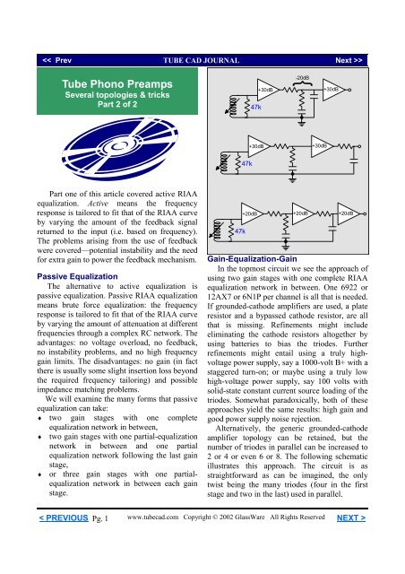
We will examine the many forms that passive<br />
equalization can take:<br />
♦ two gain stages with one complete<br />
equalization network in between,<br />
♦ two gain stages with one partial-equalization<br />
network in between and one partial<br />
equalization network following the last gain<br />
stage,<br />
♦ or three gain stages with one partialequalization<br />
network in between each gain<br />
stage.<br />
47k<br />
+20dB<br />
+20dB<br />
+20dB<br />
Gain-Equalization-Gain<br />
In the topmost circuit we see the approach of<br />
using two gain stages with one complete <strong>RIAA</strong><br />
equalization network in between. One 6922 or<br />
12AX7 or 6N1P per channel is all that is needed.<br />
If grounded-cathode amplifiers are used, a plate<br />
resistor and a bypassed cathode resistor, are all<br />
that is missing. Refinements might include<br />
eliminating the cathode resistors altogether by<br />
using batteries to bias the triodes. Further<br />
refinements might entail using a truly highvoltage<br />
power supply, say a 1000-volt B+ with a<br />
staggered turn-on; or maybe using a truly low<br />
high-voltage power supply, say 100 volts with<br />
solid-state constant current source loading of the<br />
triodes. Somewhat paradoxically, both of these<br />
approaches yield the same results: high gain and<br />
good power supply noise rejection.<br />
Alternatively, the generic grounded-cathode<br />
amplifier topology can be retained, but the<br />
number of triodes in parallel can be increased to<br />
2 or 4 or even 6 or 8. The following schematic<br />
illustrates this approach. The circuit is as<br />
straightforward as can be imagined, the only<br />
twist being the many triodes (four in the first<br />
stage and two in the last) used in parallel.<br />
< PREVIOUS Pg. 1<br />
www.tubecad.com Copyright © 2002 GlassWare All Rights Reserved NEXT >
+300V<br />
40k<br />
25k<br />
63.6k<br />
+140V<br />
+150V<br />
.22µF<br />
150<br />
10.6k<br />
1M<br />
12AX7<br />
300<br />
12AX7 12AX7 12AX7<br />
.01µF<br />
12AT7 12AT7<br />
47k<br />
1k<br />
1M<br />
1k 1k 1k 600 600<br />
.03µF<br />
Parallel <strong>Tube</strong>s<br />
The usual disadvantage of using many tubes<br />
in parallel is the greatly increased input<br />
capacitance, but in a phono preamp this<br />
capacitance works in our favor. Phono cartridges<br />
like to be loaded by capacitance, as the<br />
capacitor's declining impedance with increasing<br />
frequency helps to damp the cartridge's high<br />
frequency resonances. And the second gain<br />
stage’s increased input capacitance only helps to<br />
complete the passive equalization network's own<br />
internal need for a final shunting capacitance.<br />
On the other hand, the usual advantage to<br />
many parallel tubes lies in the lower output<br />
impedance and lower noise figure, both being<br />
highly desirable in a phono preamp. Like many<br />
resistors held in parallel, many tubes held in<br />
parallel lower the effective resistance of the<br />
bundle. In other words, the effective rp of 6<br />
12AX7s held in parallel is one sixth (about 10k)<br />
that of one 12AX7 (about 62k).<br />
Furthermore, the triode’s own r p gives rise to a<br />
noise similar to the noise a high resistance<br />
resistor would bring to a circuit. And like the<br />
resistor, the lower the effective rp, the lower the<br />
resistance noise. In other words, six 12AX7s<br />
held in parallel are six times lower in this type of<br />
noise than a single 12AX7. Why not use three or<br />
five triodes in parallel In other words, why<br />
should only an even number of triodes be used<br />
If the triode you are using comes one to the<br />
envelope, then any number of triodes can be<br />
placed in parallel. But if the triode comes two to<br />
an envelope, such as the 6DJ8, 6N1P or 12AX7<br />
does, then an even number is better. Why<br />
The logic is simple: particularly, in a phono<br />
stage, where millivolt signals are amplified, we<br />
do not want any interaction between the triodes<br />
in a tube envelope. With all the triodes in an<br />
envelope seeing the same input signal, the<br />
interaction is minimized.<br />
The calculation of the equalization network's<br />
values requires taking into account the output<br />
impedance of the first stage and the input<br />
resistance and capacitance of the second gain<br />
stage. Assuming a bypassed cathode resistor, the<br />
output impedance is easily derived from taking<br />
the effective rp of the input tubes in parallel and<br />
placing this value in parallel with the plate<br />
resistor's value, which is added to the 63.6k<br />
resistor’s value. The input capacitance, i.e. the<br />
Miller-effect capacitance, is derived from taking<br />
the cathode-to-plate capacitance and multiplying<br />
it by the gain of the second grounded-cathode<br />
amplifier and then adding this sum to the gridto-cathode<br />
capacitance. This capacitance adds to<br />
the .01 µF capacitor’s value, which brings the<br />
equalization network into the correct alignment.<br />
Of course, a two-gain stage, passive<br />
equalization layout is not limited to groundedcathode<br />
amplifiers. In fact, as long as there are<br />
two gain stages bridged by a passive<br />
equalization network, just about any tube<br />
amplifier circuit can be used: the SRPP, the<br />
cascode, the grounded-grid amplifier (with some<br />
tweaking), and the common-cathode amplifier.<br />
Other circuits that could be used are the<br />
constant-current-draw amplifier, the plate<br />
follower, and the two tube feedback pair.<br />
< PREVIOUS Pg. 2<br />
www.tubecad.com Copyright © 2002 GlassWare All Rights Reserved NEXT >
+118V<br />
9V<br />
9V<br />
300<br />
+100V<br />
47k<br />
200<br />
Rak<br />
+120V<br />
+220V<br />
Actively loaded (constant current source)<br />
grounded-cathode amplifier<br />
Actively Loaded Grounded-Cathode<br />
Let’s move slowly through some of the<br />
possible candidates for the first gain stage. The<br />
simplest variation on the grounded-cathode<br />
amplifier we have already covered, entailing<br />
using more triodes in parallel. Moving up in<br />
complexity, the actively-loaded groundedcathode<br />
amplifier finds its plate resistor replaced<br />
by another triode that functions as an active<br />
load. Depending on the size of its cathode<br />
resistor, the effective impedance this load<br />
presents to the bottom triode can easily be much<br />
larger than the plate resistor it replaces. The<br />
formula is a simple one:<br />
Z = r p + (µ + 1)R k ,<br />
where, µ equals the triode’s amplification factor<br />
(mu). For example, a 12AX7 with 20k cathode<br />
resistor would represent an impedance of<br />
2,082,000 = 62k + (100 +1)20,000.<br />
Just 1-mA against a resistor with this value<br />
would develop a voltage of 2,080-volts! Yet,<br />
both triodes could easily operate with a B+<br />
voltage of only 300-volts. Unfortunately, using a<br />
20k cathode resistor with a 12AX7 will require<br />
using an extra coupling capacitor, as a 20k<br />
resistor would bias the tube down to near cutoff.<br />
Rk<br />
1M<br />
Here is a trivia question: How large a value<br />
of cathode resistor is needed to completely turn<br />
off the 12AX7 A trick question doubtless, for<br />
no cathode resistor can be large enough to turn<br />
off the tube, as the only way a negative bias<br />
voltage can develop across the resistor is when<br />
the tube conducts — which means it cannot be<br />
turned off. While we are on the topic of tricks,<br />
one strategy for increasing the effective load<br />
impedance of the active load without having to<br />
resort to an extra coupling capacitor is to run the<br />
triodes dissimilarly. Normally, Rak would equal<br />
Rk, but they can differ in value. Using different<br />
values means that the triodes will see different<br />
cathode-to-plate voltages, while seeing the same<br />
current. For example, equal resistor values<br />
would yield an equal voltage across each triode.<br />
Increasing Rak’s value will increase the voltage<br />
across the top triode, but diminish the voltage<br />
across the bottom triode. Given a 200-volts B+<br />
power supply, a good ratio might be 130-volts<br />
for the top tube and 70-volts for the bottom tube.<br />
Thus, we have increased the value of Rak,<br />
and the effective impedance of the active load at<br />
the same time, without having resorted to adding<br />
an extra capacitor. However, if we desire the<br />
highest gain, the most linearity, and the lowest<br />
amount of power supply noise at the output, then<br />
a coupling capacitor must be added, as that is<br />
simply the price we pay for using a much larger<br />
value for the resistor Rak.<br />
47k<br />
200<br />
Rak<br />
Rk<br />
B+<br />
1M<br />
< PREVIOUS Pg. 3<br />
www.tubecad.com Copyright © 2002 GlassWare All Rights Reserved NEXT >
SRPP Amplifier<br />
+220V<br />
Moving the output from the bottom tube’s<br />
plate to the top tube’s cathode transforms the<br />
actively loaded grounded-cathode amplifier into<br />
the SRPP. Thus, all the same tricks and<br />
1M<br />
+120V<br />
topological variations apply to this circuit as did<br />
Rk<br />
to the actively loaded grounded-cathode<br />
amplifier. See SRPP Deconstructed or SRPP<br />
Rak<br />
Decoded or SRPP Once Again. Understand that in<br />
+100V<br />
a phono preamp, the SRPP functions more as a<br />
200<br />
pure voltage amplifier and less as a power<br />
amplifier, so that much of the criticisms lodged<br />
1M at the SRPP do not apply in this application.)<br />
47k<br />
Rk<br />
102k<br />
+220V<br />
+118V<br />
Two topological variations present<br />
themselves: the auto bias version, shown above<br />
and the fixed-bias version shown below.<br />
102k<br />
2M<br />
+118V<br />
300<br />
+220V<br />
118k<br />
2M<br />
300<br />
+120V<br />
Rak<br />
+100V<br />
200<br />
1M<br />
118k<br />
+120V<br />
Rak<br />
47k<br />
Rk<br />
+100V<br />
47k<br />
200<br />
The danger hidden in any multi-tube circuit<br />
that holds one tube atop the other is the chance<br />
of exceeding the maximum cathode-to-heater<br />
voltage of the tube, usually about 100 volts. The<br />
workaround is to use two heater power supplies,<br />
one referenced to ground (or a few tens of volts<br />
above ground) and the other referenced to some<br />
higher voltage, such as 120 volts.<br />
Rk<br />
1M<br />
Fixed-voltage referenced SRPP amplifier<br />
While the SRPP offers a much lower output<br />
impedance than the grounded-cathode amplifier,<br />
it is more sensitive to reactive loads.<br />
Consequently, the passive equalization’s<br />
impedance values should be kept high (i.e. high<br />
resistor values and low capacitor values), which<br />
unfortunately will increase the noise from the<br />
equalization network. Possibly the best<br />
technique might be to preload the SRPP’s output<br />
with a low-valued fixed resistance to shunt out<br />
much of the network’s varying impedance, say<br />
10k, or whatever value yields the lowest<br />
distortion.<br />
< PREVIOUS Pg. 4<br />
www.tubecad.com Copyright © 2002 GlassWare All Rights Reserved NEXT >
+100V<br />
47k<br />
1M<br />
200<br />
Rak<br />
Rk<br />
+220V<br />
+120V<br />
Auto-bias SRPP amplifier<br />
Cascode<br />
The cascode offers more potential gain than<br />
any of the previous circuits, with the final gain<br />
often far exceeding the mu of the triode.<br />
Rk<br />
1M<br />
While the extra gain is welcome, the worst<br />
PSRR figure of any of the circuits under<br />
consideration is not. A workaround was<br />
presented in the <strong>Tube</strong> <strong>CAD</strong> <strong>Journal</strong>’s first issue,<br />
March 1999, which offered a way to eliminate<br />
the power supply noise at the output. This<br />
technique works at reducing the power supply<br />
noise at the output by introducing a portion of<br />
the power supply noise to the top triode’s grid,<br />
where it will be amplified in anti-phase to the<br />
noise at the B+ connection. (Many do not realize<br />
that the top triode is capable of gain, which is<br />
not the case with FETs or transistors in place of<br />
the triode.)<br />
The triode’s r p makes the difference, as the<br />
bottom triode in effect becomes simply a large<br />
valued cathode resistor. Setting the ratio<br />
between capacitors, C2 and C1, to match the<br />
amplification plus one from the top triode will<br />
ensure that the noises cancel at the top triode’s<br />
plate. For example, if the top triode realizes a<br />
gain of 3, then the ratio should be 2:1, as this<br />
would equal 3.<br />
Ra<br />
+200V<br />
2M<br />
+300V<br />
Ra<br />
C2<br />
2M<br />
+300V<br />
+100V<br />
1M<br />
+200V<br />
+100V<br />
1M<br />
200<br />
1M<br />
200<br />
1M<br />
C1<br />
47k<br />
47k<br />
Cascode amplifier<br />
The cascode’s gain roughly equals the<br />
triode’s Gm against Ra:<br />
Gain = µR a .<br />
(R a + R p ) / (µ + 1) +r p<br />
Noise-nulled cascode amplifier<br />
< PREVIOUS Pg. 5<br />
www.tubecad.com Copyright © 2002 GlassWare All Rights Reserved NEXT >
DC-Cascaded Amplifier<br />
The next possible circuit for the first stage is<br />
the cascaded amplifier. Here one groundedcathode<br />
amplifier cascades into another. In the<br />
schematic below, the connection is capacitor<br />
free, i.e. DC coupled. Each triode sees the same<br />
cathode-to-plate voltage, with resistor R taking<br />
up slack voltage. This circuit yields a huge gain<br />
that would be suitable for MC cartridge use.<br />
<strong>Tube</strong> <strong>CAD</strong><br />
+200V<br />
Ra<br />
Ra<br />
Ra<br />
+300V<br />
+200V<br />
300<br />
1M<br />
+100V<br />
+102V<br />
200<br />
R<br />
47k<br />
Rk<br />
Grounded-Grid Amplifier<br />
The grounded-grid amplifier does not invert<br />
the signal’s phase at its output and it offers a low<br />
input impedance, as the input is the cathode<br />
rather than the grid. A low input impedance<br />
(100-600 ohms) is great for MC cartridges, but<br />
not so great for MM cartridges, which prefer to<br />
see an impedance between 10k to 47k.<br />
Since the cathode is the input of this circuit,<br />
DC coupling becomes difficult, as ground-level<br />
DC coupling would require using a negative<br />
power supply and a negative grid voltage to<br />
place the cathode at 0 volts. A DC servo loop<br />
would help, but the cartridge would still be<br />
susceptible to damage at turn on, when the tube<br />
just starts to conduct and the servo might be too<br />
slow to prevent a large DC offset at the cathode.<br />
Consequently, a coupling capacitor is the safer<br />
approach.<br />
<strong>Tube</strong> <strong>CAD</strong> does the hard math for you.<br />
This program covers 13 types of tube<br />
circuits, each one divided into four<br />
variations: 52 circuits in all. <strong>Tube</strong> <strong>CAD</strong><br />
calculates the noteworthy results, such as<br />
gain, phase, output impedance, low<br />
frequency cutoff, PSRR, bias voltage, plate<br />
and load resistor heat dissipations. Which<br />
tube gives the most gain <strong>Tube</strong> <strong>CAD</strong>'s<br />
scenario comparison feature shows which<br />
tube wins.<br />
Windows 95/98/Me/NT/2000/XP<br />
For more information, please visit our Web site :<br />
www.glass-ware.com<br />
< PREVIOUS Pg. 6<br />
www.tubecad.com Copyright © 2002 GlassWare All Rights Reserved NEXT >
Ra<br />
C2<br />
240k<br />
+250V<br />
+110V<br />
1M<br />
1M<br />
R<br />
10µF<br />
Rk<br />
Grounded-grid amplifier<br />
In the above circuit we see a grounded-grid<br />
amplifier cascading into a cathode follower. The<br />
coupling capacitor may seem too large in value,<br />
where in fact it is probably too small in value.<br />
The grounded-grid amplifier’s input impedance<br />
is equal to the sum of the rp and the plate<br />
resistor divided by mu +1:<br />
Z in = (R a + r p ) / (mu +1)<br />
Given a 6DJ8 as the tube, the input impedance<br />
equals 380 ohms in parallel with the cathode<br />
resistor’s 200 ohms (about 130 ohms). The low<br />
frequency cutoff is found by the following<br />
formula:<br />
F low = 159155/(Z in + Z cartridge )/C<br />
So in this example, 50 µF equals a –3 dB cutoff<br />
frequency of about 25 Hz. Using a higher rp<br />
tube such as a 6072, 5751, or 12AX7 would<br />
increase the input impedance, but at the cost of<br />
more noise. (The usual compromise is to use an<br />
electrolytic capacitor in parallel with one or two<br />
high quality film caps.)<br />
The grounded-grid amplifier allows an easy<br />
noise canceling trick, as a small quantity of<br />
power supply noise can be injected at its grid,<br />
causing an inverted noise signal to appear at its<br />
plate, which then mixes and cancels with the<br />
power supply noise there in much the same<br />
manner as it did in the cascode noise-nulled<br />
circuit.<br />
Noise-nulled grounded-grid amplifier<br />
Bootstrapped Compound Amplifier<br />
This sleeper of a circuit was described in length<br />
in the “SRPP Deconstructed” article from earlier<br />
this year. In a nutshell, this circuit works to<br />
magnify the first triode’s plate resistor, making it<br />
effectively much larger, so that the gain from the<br />
first stage can nearly equal its mu. The tradeoff is<br />
that the second stage no longer has a low output<br />
impedance similar to a cathode follower. Still, this<br />
deserves a second look.<br />
1M<br />
300<br />
10µF<br />
47k<br />
5k<br />
+150V<br />
5k<br />
+100V<br />
6DJ8<br />
+12V<br />
Rk<br />
+2V<br />
10k<br />
6DJ8<br />
+10V<br />
C1<br />
+102V<br />
+200V<br />
200 10k<br />
1M<br />
Bootstrapped compound amplifier<br />
< PREVIOUS Pg. 7<br />
www.tubecad.com Copyright © 2002 GlassWare All Rights Reserved NEXT >
Two-tube-feedback pair<br />
One possible measure of success might be a<br />
simple coupling capacitor count, with less being<br />
better than more. By this standard, the two-tubefeedback<br />
pair would seem a sure loser, with its<br />
internal coupling capacitor and its two output<br />
coupling capacitors...but then, maybe not.<br />
20k<br />
20k<br />
+100V<br />
2.2µF<br />
+300V<br />
+200V<br />
200<br />
Ra<br />
+100V<br />
300<br />
Ra<br />
Ra<br />
+200V<br />
+300V<br />
+102V<br />
Rfb<br />
+100V<br />
6DJ8<br />
1M<br />
+2V<br />
.22µF<br />
10k<br />
47k<br />
Rk<br />
6DJ8<br />
+2V<br />
47k<br />
200 200<br />
1M<br />
DC-cascaded feedback pair amplifier<br />
Why so many coupling capacitors If we<br />
attach the feedback resistor directly to the<br />
second triode’s plate, the first triode’s cathode<br />
voltage and the second triode’s plate voltage will<br />
be thrown off. Using a coupling capacitor<br />
between plate and feedback resistor isolates the<br />
feedback resistor from the plate, but not from the<br />
first triode’s cathode, which will impose its DC<br />
offset on the resistor; thus the need for the<br />
secondary coupling capacitor.<br />
Improved DC-cascaded feedback pair amplifier<br />
Direct coupling between tubes eliminates the<br />
internal coupling capacitor and accepting the<br />
consequences of retaining the first triode’s<br />
cathode voltage at the output eliminates the<br />
second coupling capacitor.<br />
In the circuit below, we see a pair of two-tube<br />
feedback amplifiers being used in a way that<br />
only brings the count of coupling capacitor to<br />
three. This arrangement is possible because the<br />
second triode's cathode resistor is bypassed<br />
(which it would probably be even if the coupling<br />
capacitor had been retained), which allows us to<br />
specify the resistor’s value arbitrarily.<br />
+300V<br />
20k<br />
10k<br />
+200V<br />
1µF<br />
75k<br />
+2V<br />
20k<br />
10k<br />
+200V<br />
1µF<br />
.22µF<br />
300<br />
300<br />
+100V<br />
10k<br />
+100V<br />
10k<br />
6DJ8<br />
6DJ8<br />
300 .03µF 300<br />
+102V +102V<br />
6DJ8 +2V 6DJ8 +4V<br />
.01µF<br />
47k<br />
200 10k<br />
10.6k<br />
400 10k<br />
1M<br />
< PREVIOUS Pg. 8<br />
www.tubecad.com Copyright © 2002 GlassWare All Rights Reserved NEXT >
+300V<br />
20k 10k 1µF<br />
20k 10k<br />
+200V<br />
75k +2V<br />
+200V<br />
+100V<br />
300<br />
300<br />
6DJ8<br />
10k<br />
+100V<br />
+202V<br />
.22µF<br />
300<br />
6DJ8<br />
6DJ8<br />
.01µF 300<br />
+102V +102V<br />
20k<br />
6DJ8 +2V<br />
.03µF<br />
6DJ8 +4V<br />
47k<br />
200 10k<br />
10.6k<br />
400 10k<br />
1M<br />
In other words, because the triode’s cathode<br />
finds a low-impedance path to ground through<br />
the bypass capacitor, the triode doesn't see its<br />
cathode resistor’s value in its AC operation; in<br />
its DC operation, however, the grid’s DC<br />
voltage and the cathode resistor’s value set the<br />
idle current through the triode.<br />
The feedback loop encompasses the output<br />
coupling capacitor and purposely allows the DC<br />
voltage from the first triode's cathode resistor to<br />
be relayed to the other side of this capacitor.<br />
This small positive DC bias allows the use of a<br />
higher valued cathode resistor for the following<br />
gain stage's input tube, which helps us realize a<br />
lower gain from the second gain stage without<br />
having low-valued feedback resistor drag down<br />
the output too severely.<br />
The last coupling capacitor is needed to shield<br />
the volume control and the line stage input from<br />
the DC voltage present on the feedback loop<br />
(potentiometers should never see a constant DC<br />
current flow through their scraper).<br />
In the circuit above, we see that adding a<br />
cathode follower eliminates the need for the last<br />
coupling capacitor. The 20k feedback resistor is<br />
now is no longer in parallel with the plate<br />
resistor, which will result in higher gain from the<br />
that triode because its plate is sheltered by the<br />
cathode follower. Now the total coupling<br />
capacitor count has fallen to two and we have<br />
retained the feedback loops, while improving the<br />
stability of the amplifier. Not bad.<br />
SE Amp <strong>CAD</strong><br />
For more information, please visit our<br />
Web site or write us at:<br />
GlassWare<br />
PO Box 231<br />
Fenton, MI 48430 USA<br />
www.glass-ware.com<br />
< PREVIOUS Pg. 9<br />
www.tubecad.com Copyright © 2002 GlassWare All Rights Reserved NEXT >
Fresh Topology<br />
If fewer caps are better, is it possible to build<br />
a multi-tube passive phono preamp with only<br />
one coupling capacitor In the circuit below we<br />
see a constant-current-draw amplifier feeding a<br />
passive equalization network, which then feeds a<br />
common-cathode amplifier, amazingly DCcoupled<br />
all the way to the output coupling<br />
capacitor. The 100-volt DC bias voltage on the<br />
network's output allows us to use a rather large<br />
valued common-cathode resistor (5200-ohms)<br />
without having to use a negative power supply.<br />
The enemy of all preamplifiers is noise. Some<br />
noises are difficult if not impossible to counter,<br />
such as tube microphonics. One source of noise,<br />
however, can be reduced through an<br />
understanding and the careful applications of<br />
noise mulling techniques. The elaborate circuitry<br />
at the common-cathode's second triode's grid<br />
(the 1-meg resistor and the two capacitors in<br />
series) is there to allow canceling of the power<br />
supply’s noise from its output by introducing a<br />
small amount of power supply noise at this grid<br />
by effectively voltage dividing the power<br />
supply’ noise. Thus this portion of the power<br />
supply noise can be amplified and phase<br />
inverted at the output, where it will cancel with<br />
the power supply noise at the plate resistor. A<br />
single coupling capacitor is in itself a worthy<br />
enough goal, but by adding noise cancellation,<br />
we arrive at a truly desirable phono stage.<br />
Notice how the 3.3k resistor in the power<br />
supply serves double duty by filtering the B+<br />
voltage for the first stage and achieving a<br />
matched plate voltage for the second stage’s<br />
triodes. A safe bet would be a floating heater<br />
power supply that was referenced to about 70<br />
volts to prevent exceeding the triode’s cathodeto-heater<br />
voltage limits.<br />
(Of course, my brief outlining of this circuit is<br />
not the correct tube-guru procedure to promoting<br />
a new design. The generally accepted guru<br />
approach would be to write a long article for a<br />
mainstream—or is minor-stream closer to the<br />
truth—audio magazine, such as the late Sound<br />
Practices. The article would then go on to slam<br />
all other tube phono preamp designs and go on<br />
to explain how the preamp sounds far better than<br />
a friend’s supremely-expensive-tube-namebrand<br />
preamp. The article would explain how<br />
the preamp must be made with both the carbon<br />
resistors and the capacitors culled from a 1961<br />
RCA BW television; in fact, the preamp would<br />
be named the RCA Uni-Cap preamp, or better<br />
still, the RCA-Unicorn preamp. This circuit<br />
would then live and propagate, becoming usergroup<br />
and chat-room fodder; finally, someone<br />
would use a different tube and claim to have<br />
invented a whole new topology or it might<br />
mutate into a simpler circuit, as few would<br />
understand how the noise cancellation works<br />
and what is not understood is not needed; right<br />
Oh, what a tube-audio cynic I have become.)<br />
3.3k<br />
+300V<br />
10k<br />
300<br />
100µF<br />
+200V<br />
10k<br />
C1<br />
+100V<br />
6DJ8<br />
+102V<br />
+200V<br />
.22µF<br />
300<br />
75k<br />
300<br />
1M<br />
+102V<br />
47k<br />
6DJ8<br />
1µF<br />
+2V<br />
10k<br />
100<br />
.029µF<br />
10.6k<br />
.01µF<br />
6DJ8<br />
+104V 6DJ8<br />
5.2k<br />
C2 1M<br />
< PREVIOUS Pg. 10<br />
www.tubecad.com Copyright © 2002 GlassWare All Rights Reserved NEXT >
Split Equalization Passive <strong>Preamps</strong><br />
Like the active alternative, the passive<br />
equalization network can be split into two<br />
sections, one covering the 50 to 500-Hz shelving<br />
function and another covering the 2122-Hz lowpass<br />
transition point.<br />
A)<br />
in<br />
B)<br />
in<br />
50Hz<br />
2122Hz<br />
R1<br />
R1<br />
500Hz<br />
R2<br />
C1<br />
C1<br />
out<br />
out<br />
20kHz<br />
20dB<br />
20dB<br />
R1 = 9R2<br />
R2C1 = 318µS<br />
(R1 + R2)C1 = 3180µS<br />
R1C1 = 75µS<br />
Two resistors and one capacitor are all that is<br />
needed to create a low-frequency shelving<br />
network. At low frequencies, the capacitor<br />
effectively isolates resistor R1 from resistor R2<br />
and ground, so no attenuation occurs. At high<br />
frequencies, the capacitor effectively bridges<br />
resistors R1 and R2, creating a voltage divider<br />
and reducing the signal by the resistor ratio.<br />
The usual approach is to use three gain stages<br />
separated by two passive equalization networks,<br />
for example, the circuit below. This scheme<br />
greatly reduces the gain requirement from each<br />
gain stage. For example, you would be hard<br />
pressed to find triodes that could realize a gain<br />
higher than 70 in the two gain stage scheme,<br />
which would yield only a final gain of 50 dB<br />
after equalization.<br />
But that same 50 dB of gain could be had by<br />
cascading three stages with a gain of 15 times<br />
the input (23 dB). In the circuit below, each<br />
6DJ8-based grounded-cathode amplifier<br />
achieves a gain of 25 (+28 dB) in this circuit,<br />
which brings the total gain to +64 dB after<br />
equalization!<br />
If the values of the shelving network and the<br />
low-pass filter do not look correct, for example,<br />
98.7k instead of 90k and 7.55k instead of 7.5k,<br />
the reason is that these values have been<br />
adjusted to compensate for the 1M grid resistors<br />
that follow and are effectively in parallel with<br />
the resistors. Thus, 1M in parallel with 100k<br />
yields 90k and 1M in parallel with 7.55k yields<br />
7.5k. (Actually, we should also include each<br />
cathode follower’s output impedance in the mix;<br />
be sure to read the last page)<br />
+200V<br />
10k<br />
300<br />
10k<br />
300<br />
10k<br />
300<br />
300<br />
+100V<br />
6DJ8<br />
+102V<br />
98.7k<br />
.1µF<br />
300<br />
+100V<br />
6DJ8<br />
+102V<br />
7.55k<br />
.1µF<br />
300<br />
+100V<br />
6DJ8<br />
+102V<br />
1µF<br />
47k 1µF<br />
6DJ8 +2V<br />
10k<br />
100<br />
.0318µF<br />
10k<br />
1M<br />
6DJ8 +2V<br />
1µF<br />
10k<br />
100<br />
.01µF<br />
1M<br />
6DJ8 +2V<br />
1µF<br />
10k<br />
100<br />
1M<br />
< PREVIOUS Pg. 11<br />
www.tubecad.com Copyright © 2002 GlassWare All Rights Reserved NEXT >
+200V<br />
10k<br />
300<br />
10k<br />
300<br />
300<br />
+100V<br />
6DJ8<br />
+102V<br />
98.7k<br />
.1µF<br />
300<br />
+100V<br />
6DJ8<br />
+102V<br />
8.1k<br />
.47µF<br />
47k<br />
6DJ8 +2V<br />
1µF<br />
10k<br />
100<br />
.0318µF<br />
10k<br />
1M<br />
6DJ8 +2V<br />
1µF<br />
10k<br />
100<br />
.01µF<br />
1M<br />
100k<br />
Another possible variation would be to use<br />
two gain stages, with the shelving half of the<br />
equalization network in between the two gain<br />
stages and the 2122-Hz RC low-pass filter<br />
following the output. This topology once again<br />
begs the irksome question of sufficient gain, as<br />
the 6DJ8-based gain stage would only realize a<br />
total phono preamp gain of +36 dB, which might<br />
be sufficient with some high-output moving<br />
magnet cartridges or with high-gain line stages.<br />
Still, this configuration would greatly reduce<br />
the preamp's output noise as it equalizes the<br />
signal, as whatever noise is present above 2122<br />
Hz, no matter its cause, would also be attenuated<br />
by the final equalization network. (The output<br />
impedance of the final gain stage and the<br />
resistance of the volume control have been<br />
factored into the design of both equalization<br />
networks.)<br />
A Different Approach<br />
Notice how close the inverse <strong>RIAA</strong><br />
equalization curve is to a 50 Hz low-pass filter,<br />
excepting the flattening at 1 KHz. (In fact, I<br />
believe that some cheap phono players back in<br />
the 60’s used only a low-pass filter with a –3db<br />
point of 70 Hz or so.)<br />
We can rearrange the sequence of the subnetworks<br />
so that the low-pass filter is tuned to<br />
50 Hz and the shelving network applies to<br />
frequencies between 500 Hz and 2122 Hz, but<br />
this time the shelving boosts higher frequencies<br />
rather than attenuating them.<br />
50Hz<br />
500Hz<br />
2122Hz<br />
500Hz<br />
20dB<br />
12.55dB<br />
Below, circuit A defines the low-pass<br />
function, while circuit B defines the shelving<br />
function.<br />
A)<br />
in<br />
B)<br />
in<br />
R1<br />
C1<br />
R2<br />
C1<br />
R1<br />
out<br />
out<br />
R1C1 = 3180µS<br />
R2/R1 = 3.244<br />
(R1 || R2)C1 = 75µS<br />
C1R2 = 318<br />
< PREVIOUS Pg. 12<br />
www.tubecad.com Copyright © 2002 GlassWare All Rights Reserved NEXT >
+210V<br />
5.5k<br />
8k<br />
11k<br />
+100V<br />
.0099µF<br />
+130V<br />
117k<br />
+130V<br />
.47µF<br />
300 32.5k<br />
6DJ8 +2V 6DJ8 +2V<br />
300<br />
.03µF<br />
6DJ8 +24V<br />
.1µF 300<br />
6DJ8 +2V<br />
1M<br />
47k<br />
200<br />
200<br />
8.7k<br />
24k<br />
1M<br />
200<br />
Cascading these two functions results in the<br />
same curve as the traditional two function<br />
combination creates. So, why bother with this<br />
alternate approach Beyond the mental<br />
stretching, which is always for the good, this<br />
alternative approach engenders new phono<br />
preamp topologies, with some interesting<br />
benefits and one negative. The first benefit is<br />
that the 50Hz low-pass filter can filter more<br />
power supply noise away from the output signal<br />
than the 2122Hz can.<br />
.1µF<br />
1M<br />
+10V<br />
200<br />
47k<br />
Ra<br />
1200<br />
10k<br />
91k<br />
R1<br />
C1<br />
+12V<br />
C2<br />
Rk<br />
.266µF<br />
+210V<br />
.0318µF<br />
A single-triode phono preamp<br />
Second, the 500Hz to 2122Hz shelving<br />
network can be implemented within one<br />
grounded–cathode amplifier, i.e. a single triode<br />
<strong>RIAA</strong> equalized preamp. Usually a cathode<br />
resistor is bypassed with a large valued<br />
capacitor, so as to ensure adequate lowfrequency<br />
response. But if the bypass capacitor’s<br />
value is reduced greatly, it introduces a shelving<br />
function, wherein the high-frequency gain is<br />
greater than the low-frequency gain, with the<br />
ratio being equal to the bypassed gain over the<br />
unbypassed gain or<br />
1 .<br />
Ratio = 1 + (mu + 1)R k<br />
R a + r p<br />
The transition frequencies are based on the<br />
capacitor’s value and the time constants it forms<br />
with the triode’s r p and its plate and cathode<br />
resistor values:<br />
R k C k = 75µS<br />
[(R a + r p )/(mu + 1) || R k ]C k = 318µS<br />
Of course, one triode is not going to provide<br />
enough gain in most cases, so additional gain<br />
stages will be needed.<br />
The overarching liability of this different<br />
path to <strong>RIAA</strong> equalization is the –12dB insertion<br />
loss beyond the expected losses, which brings it<br />
1kHz insertion loss down to –32dB. With this<br />
equalization network, the near DC and subsonic<br />
frequencies are reduced by –12dB, whereas the<br />
traditional path retained all of the gain at the<br />
bottom of range. Now, -12dB is just too much to<br />
pay in most two-gain-stage phono preamps, but<br />
it is almost nothing in a three-gain-stage preamp,<br />
where the problem is usually having too much<br />
gain. Still the advantage of using a portion of the<br />
equalization network in double duty either, as a<br />
pseudo coupling capacitor or a partial cathodebypass<br />
capacitor, is tempting.<br />
< PREVIOUS Pg. 13<br />
www.tubecad.com Copyright © 2002 GlassWare All Rights Reserved NEXT >
Hybrid Phono Circuits<br />
Hybrid circuits were mentioned in that distant<br />
first half of this article, but giving this topic a<br />
fair hearing would require more pages than I can<br />
write before we enter a new year. So what<br />
follows are a few schematics that offered as<br />
starting points for some new projects and<br />
articles.<br />
10k<br />
+110V<br />
+210V<br />
out<br />
MOSFETs can also be used, but not as the<br />
input to a hybrid circuit. A better place for the<br />
MOSFET might be as a grounded-source<br />
amplifier that an input triode could cascade into.<br />
If a P-channel MOSFET is used, the MOSFET<br />
can be DC coupled to the triode's plate resistor.<br />
The complete circuit will not invert the phase at<br />
the output. Thus, a feedback loop could be<br />
returned to the triode's cathode, which would<br />
give the triode control over the MOSFET's<br />
output.<br />
+210V<br />
10k<br />
9.7k<br />
6DJ8<br />
+9V<br />
300<br />
+7V<br />
200<br />
200<br />
300<br />
+100V<br />
+52V<br />
47k<br />
10<br />
47k<br />
6DJ8 +2V<br />
100<br />
5k<br />
Hybrid Loftin-White first stage<br />
FETs are marvelously quiet. The low noise<br />
from the best FETs make the quietest tube sound<br />
thunderous in comparison. I have always<br />
thought that the FET should first handle the<br />
delicate input signal from a phono cartridge and<br />
then give its amplified output to a tube, thus<br />
utilizing the best features of both technologies.<br />
But how to proceed We can make a cascode<br />
with the FET receiving the input signal or we<br />
can cascade the FET into the tube in a Loftin-<br />
White like configuration, which may result in<br />
lower noise and a more tube-like sound.<br />
Note the DC coupling between FET and<br />
triode and how the triode and bypass capacitor<br />
shield the FET from the power supply noise.<br />
Another avenue I haven't had time to<br />
investigate is using a FET only in its triode<br />
region of operation, wherein it exhibits r p !<br />
Hybrid triode-MOSFET first stage<br />
Even the lowly IC Op-Amp could be used<br />
as the first stage of two-gain stage passive<br />
equalization preamp. The IC can be quiet and it<br />
allows DC coupling with the tube, if a small DC<br />
offset is put in place by using an additional<br />
resistor in the IC's feedback loop. This resistor<br />
applies a small amount of current from the IC's<br />
positive power supply rail, which will cause the<br />
Op-Amp's output to establish a negative DC<br />
offset at the output. Unfortunately, we cannot<br />
connect the resistor to the triode's plate, as this<br />
would create a positive feedback loop, not a<br />
negative feedback loop. (A second IC could be<br />
used to invert the DC signal from the plate, but<br />
this would complicate the circuit.) An AC<br />
feedback loop could wrap around the triode, but<br />
I would not want the Op-Amp's near infinite<br />
gain, and thus its near infinite potential<br />
< PREVIOUS Pg. 14<br />
www.tubecad.com Copyright © 2002 GlassWare All Rights Reserved NEXT >
feedback, to overwhelm the triode’s output. The<br />
OP-37 and other Op-Amps are much quieter<br />
than the best triode... it’s like receiving a large<br />
charitable contribution from a gangster: sure,<br />
you like the money, but at what hidden cost<br />
300<br />
200<br />
47k<br />
75k<br />
10k<br />
-15V<br />
+15V<br />
-2V<br />
10k<br />
6DJ8<br />
+100V<br />
+200V<br />
The triode then inverts the signal and a global<br />
feedback loop keeps the output’s DC offset in<br />
line (no coupling capacitor!) and it offers all of<br />
the usual advantages to using feedback, lower<br />
distortion, wider bandwidth, and lower output<br />
impedance.<br />
<strong>RIAA</strong> Program<br />
If you have been wondering Where’s the<br />
math Here it is, in the form of a Windows<br />
program. Passive <strong>RIAA</strong> EQ Calculator quickly<br />
figures six basic <strong>RIAA</strong> equalization circuits.<br />
Well, why not carry the DC coupled theme a<br />
little further and run the Op-Amp in an inverted<br />
cascode circuit, shown below. As the Op-Amp<br />
delivers current into the 200–ohm resistor, the<br />
variation in current drawn through its negative<br />
power supply pin will be transmitted to the drain<br />
load resistor, which in turn will deliver the<br />
signal to the triode below.<br />
300<br />
100<br />
47k<br />
-97V<br />
200<br />
5k<br />
20k<br />
200<br />
300<br />
+15V<br />
10k<br />
-18V<br />
0V<br />
6DJ8<br />
500<br />
+200V<br />
-95V<br />
This Windows program also displays the<br />
<strong>RIAA</strong> equalization curve and its inverse, while<br />
allowing specific frequency entry and mouse<br />
position readouts of amplitude and frequency.<br />
Added features include its ability to compensate<br />
for input impedance and load impedance in its<br />
calculations. The program is easy to use and if<br />
you have used any of the other GlassWare<br />
programs, you will have no difficulty getting<br />
results immediately from it.<br />
How much does it cost It’s free, with one<br />
string attached: it’s available at the Beige Bag<br />
Software website, www.beigebag.com where a<br />
short survey must be filled out first. (In order to<br />
make a better Spice program for the audio<br />
enthusiast, you, in other words, they need to<br />
know what you want, so it is really a win-win<br />
offer.)<br />
Hybrid inverted cascode amplifier<br />
-100V<br />
//JRB<br />
< PREVIOUS Pg. 15<br />
www.tubecad.com Copyright © 2002 GlassWare All Rights Reserved NEXT >


