Download
Download
Download

Create successful ePaper yourself
Turn your PDF publications into a flip-book with our unique Google optimized e-Paper software.
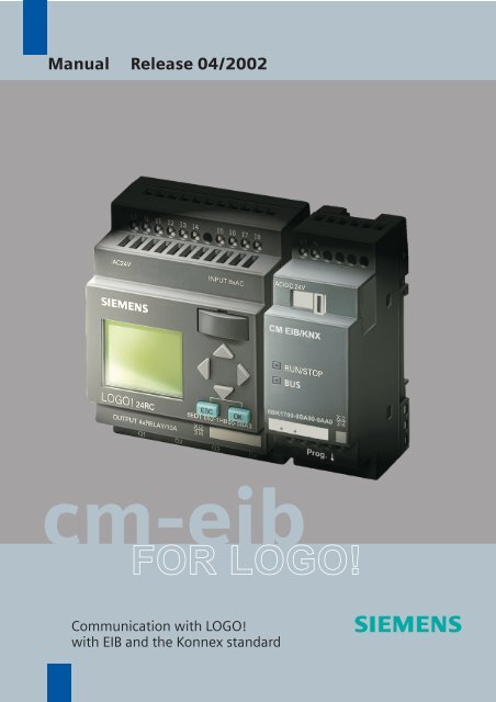
Manual Release 04/2002<br />
cm-eib<br />
FOR LOGO!<br />
Communication with LOGO!<br />
with EIB and the Konnex standard
s<br />
CM EIB/KNX<br />
LOGO! Expansion Module<br />
Manual<br />
Chapters<br />
Safety Notices<br />
1 Getting to know CM EIB<br />
2 Mounting and wiring the CM EIB<br />
3 Putting the CM EIB into operation<br />
4 Supported functions<br />
5 CM EIB specifications<br />
INDEX
CM EIB/KNX<br />
Copyright - Siemens AG 1996 to 2002 All rights reserved<br />
You may not transfer or duplicate this document or utilize or reveal its contents,<br />
unless expressly authorized in writing. In the case of a violation, you will be obliged<br />
to pay damages. All rights reserved, in particular in the event that a patent is<br />
granted or that a utility model is registered.<br />
Disclaimer of liability:<br />
We have checked that the contents of this document correctly describe the<br />
associated hardware and software. Nonetheless, it is impossible to exclude the<br />
possibility of deviations and therefore we cannot guarantee that there are no errors<br />
in this document. The information in this document is checked regularly and any<br />
necessary corrections are then made in the next release issued. We are of course<br />
thankful for any suggestions for improvements.<br />
CM EIB<br />
2 J31069-D1262-U002-A2-7618
CM EIB/KNX<br />
Table of Contents<br />
Safety Notices<br />
1 Getting to know CM EIB...................................... 5<br />
1.1 What is the CM EIB ............................................. 5<br />
1.2 The construction of the CM EIB............................. 6<br />
2 Mounting and wiring the CM EIB/KNX............... 7<br />
2.1 General guidelines ................................................. 7<br />
2.2 Wiring the CM EIB ................................................. 9<br />
2.2.1 Connecting the power supply 10<br />
2.2.2 Connecting the EIB 11<br />
3 Putting the CM EIB into operation ................... 12<br />
3.1 Step-by-step......................................................... 12<br />
3.2 The CM EIB - operational status.......................... 13<br />
3.3 Behavior in case of a fault.................................... 15<br />
4 Supported functions.......................................... 16<br />
4.1 Inputs / Outputs.................................................... 16<br />
4.2 Available communication objects......................... 18<br />
4.3 EIB configuration.................................................. 19<br />
5 CM EIB - Specifications..................................... 22<br />
CM EIB<br />
J31069-D1262-U002-A2-7618 3
CM EIB/KNX<br />
Safety Notices<br />
DANGER<br />
Indicates that death, severe bodily<br />
injury or substantial material damage<br />
will occur, if the corresponding safety<br />
measures are not taken.<br />
WARNING<br />
Indicates that death or severe<br />
bodily injury may occur, if the<br />
corresponding safety measures<br />
are not taken.<br />
CAUTION<br />
With the warning triangle, this<br />
indicates that minor bodily<br />
injury may occur, if the<br />
corresponding safety measures<br />
are not taken.<br />
CAUTION<br />
Without the warning triangle,<br />
this indicates that material<br />
damage may occur, if the<br />
corresponding safety measures<br />
are not taken.<br />
WARNING<br />
This indicates that an undesirable<br />
result or condition may occur, if the<br />
corresponding instructions are not<br />
observed.<br />
CM EIB<br />
4 J31069-D1262-U002-A2-7618
CM EIB/KNX<br />
1 Getting to know CM EIB<br />
1.1 What is the CM EIB<br />
This is the communications module (CM) for connecting the<br />
LOGO! to the EIB bus.<br />
The LOGO! communications module has been implemented<br />
as a Slave module for the LOGO control module (12/24 or<br />
115/240 Volt).<br />
The module supports communication between the LOGO!<br />
Master and external EIB devices via an EIB.<br />
The CM is a bus participant on the EIB and allows the LOGO!<br />
to communicate with other EIB devices using EIB telegrams.<br />
What are the capabilities of the CM EIB<br />
The CM transfers EIB telegrams to the LOGO! and LOGO!<br />
functions to the EIB.<br />
The CM presents the current states of the EIB devices to the<br />
LOGO!, which is thus able to use its logical functions und<br />
timers to join them together. In the process, the EIB signals<br />
can also be combined with the signals of the local LOGO!<br />
inputs and outputs. The CM then transmits every change of<br />
the output signal via the EIB.<br />
The combination of LOGO! and CM EIB gives the user a<br />
decentralized controller functionality for the EIB with the<br />
capability of setting or changing parameters or operations<br />
quickly, simply and without a programming device.<br />
CM EIB<br />
J31069-D1262-U002-A2-7618 5
CM EIB/KNX<br />
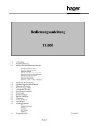
1.2 The construction of the CM EIB<br />
1. Power supply<br />
2. Bus lock slide, interface to the LOGO!<br />
3. The RUN/STOP LED for communication with LOGO!<br />
4. The BUS LED, EIB communications<br />
5. Label for the physical address<br />
6. Inputs - EIB connection<br />
7. Expansion interface to the LOGO!<br />
8. Mechanical coding - pin<br />
9. Programming button<br />
CM EIB<br />
6 J31069-D1262-U002-A2-7618
CM EIB/KNX<br />
2 Mounting and wiring the CM EIB/KNX<br />
2.1 General guidelines<br />
• The following guidelines must be observed when<br />
mounting and wiring your CM EIB:<br />
• When wiring the CM EIB, make certain that you follow all<br />
of the applicable and legally binding standards. Observe<br />
all of the relevant national and regional regulations when<br />
installing and operating the device. Check with the local<br />
authorities regarding the standards and regulations that<br />
must be observed in your special case.<br />
• Make certain that the device is de-energized.<br />
• Use only approved bus cables.<br />
• The EIB bus cables may also be laid parallel to other<br />
lines.<br />
• The CM EIB must always be installed as the last module<br />
on the right of the LOGO!, since you may not install other<br />
expansion modules onto the CM EIB.<br />
CM EIB<br />
J31069-D1262-U002-A2-7618 7
CM EIB/KNX<br />
Please note:<br />
- The CM EIB must have its own voltage supply (24V).<br />
NOTE<br />
This module may only be mounted and wired by qualified<br />
personnel, who know and observe the generally applicable<br />
guidelines and applicable regulations and standards.<br />
Observe the assembly and disassembly instructions in the<br />
LOGO! manual.<br />
WARNING<br />
The expansion module may only inserted or removed when<br />
the power is off.<br />
CM EIB<br />
8 J31069-D1262-U002-A2-7618
CM EIB/KNX<br />
2.2 Wiring the CM EIB<br />
To wire the CM EIB, use a screwdriver with a 3 mm wide<br />
blade.<br />
There is no difference between the terminals of the LOGO!<br />
and the EIB.<br />
NOTE<br />
To protect personnel against unintentional contact with the<br />
portions of the CM EIB that are conducting electricity, the<br />
appropriate national and local standards must be observed.<br />
The CM EIB is a double-insulated switching device.<br />
A protective grounding conductor is not necessary.<br />
CM EIB<br />
J31069-D1262-U002-A2-7618 9
CM EIB/KNX<br />
2.2.1 Connecting the power supply<br />
The CM EIB has been designed to serve as a Slave module<br />
for the LOGO! controller. It must be connected to a 12/24 V<br />
AC/DC supply voltage.<br />
Please observe the relevant instructions that are found in<br />
product information that was included with your equipment as<br />
well as the technical data regarding the permissible voltage<br />
tolerances, mains frequency and current consumption.<br />
Connecting<br />
How to connect the CM EIB to the power:<br />
CM EIB ..... with<br />
CM EIB ..... with<br />
DC supply<br />
AC supply<br />
Protect with a<br />
80 mA/slow action fuse, if desired (recommended).<br />
CM EIB<br />
10 J31069-D1262-U002-A2-7618
CM EIB/KNX<br />
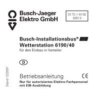
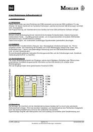
2.2.2 Connecting the EIB<br />
This connection is made using the two screw terminals (+<br />
and -).<br />
RUN/STOP<br />
BUS<br />
6BK1700-0BA00-0AA0<br />
X 2<br />
3 4<br />
Prog.<br />
+ - EIB<br />
red black<br />
Only the red – black pair is used,<br />
the white – yellow pair is not connected.<br />
You can set the CM EIB in the programming mode by<br />
pressing on the “Prog ↓” button.<br />
NOTE<br />
Don't apply too much force when pressing the “Prog ↓”<br />
button.<br />
When contact has been made, the LED will light up in<br />
orange.<br />
CM EIB<br />
J31069-D1262-U002-A2-7618 11
CM EIB/KNX<br />
3 Putting the CM EIB into operation<br />
3.1 Step-by-step<br />
1. Both the BUS and supply voltage must be present.<br />
2. Connect a PC to the serial EIB interface.<br />
3. Start ETS. Use ETS2 Version 1.2.<br />
4. Use ETS2, V.1.2 to configure the application program.<br />
5. The application program is loaded into the devices via the<br />
EIB interface. The application program is available for<br />
downloading from the LOGO! homepage<br />
(http://www.siemens.de/logo).<br />
6. In ETS, click on “Program Physical Address”.<br />
7. Press the button on the CM EIB to set the CM EIB in<br />
programming mode; the LED will light up in orange.<br />
8. When the LED goes out, the physical address has been<br />
programmed. You can now note the physical address on<br />
the device.<br />
The syntax of the physical address:<br />
Area / Line / Device<br />
XX / XX / XXX<br />
CM EIB<br />
12 J31069-D1262-U002-A2-7618
CM EIB/KNX<br />
9. The application program can now be loaded. Afterwards,<br />
the device is ready for operation.<br />
RUN/STOP<br />
BUS<br />
6BK1700-0BA00-0AA0<br />
X 2<br />
3 4<br />
Prog.<br />
+ - EIB<br />
red black<br />
10. If multiple CM EIBs have been installed in an EIB system,<br />
repeat Steps 1 to 9 for each CM EIB.<br />
11. For further details regarding the EIB installation, please<br />
read the corresponding documentation.<br />
3.2 The CM EIB - operational status<br />
The CM EIB is a LOGO! expansion module.<br />
This module has two LED displays:<br />
1. “RUN/STOP” LED Communication with the LOGO!<br />
2. “BUS” LED EIB-Bus status<br />
CM EIB<br />
J31069-D1262-U002-A2-7618 13
CM EIB/KNX<br />
The “RUN/STOP” LED will light in green, red or orange.<br />
LED Lights In<br />
Green (RUN) Red (STOP) Orange<br />
The expansion module<br />
is communicating with<br />
the device on the left.<br />
The expansion module<br />
is not communicating<br />
with the device on the<br />
left.<br />
The “BUS” LED will light in green, red or orange.<br />
The expansion<br />
module's initialization<br />
phase<br />
LED Lights In<br />
Green Red Orange<br />
Bus connection OK,<br />
communication OK,<br />
not programming<br />
mode<br />
Bus connection fault<br />
Programming mode<br />
active and bus<br />
connection OK<br />
L+ M<br />
AC/DC 24V<br />
CM EIB / KNX<br />
RUN/STOP<br />
BUS<br />
6BK1700-0BA00-0AA0<br />
X 2<br />
3 4<br />
Prog.<br />
+ - EIB<br />
CM EIB<br />
14 J31069-D1262-U002-A2-7618
CM EIB/KNX<br />
3.3 Behavior in case of a fault<br />
LOGO! - Power failure<br />
If the power to the LOGO! fails or the communications with<br />
the LOGO! Master or the communications partner to the left<br />
is interrupted, the outputs will be set to 0. The “RUN/STOP”<br />
LED will light in RED after one second.<br />
LOGO! - Power returns<br />
The LOGO! will startup and the CM will send the<br />
parameterized status.<br />
CM - Power failure<br />
All of the inputs of the EIB's LOGO! Master will be set by the<br />
LOGO! Master to 0.<br />
CM - Power returns<br />
All of the LOGO!Master outputs on the EIB will be updated.<br />
The inputs will be – depending on the EIB parameters – read.<br />
BUS - Short-circuit or interruption<br />
The inputs and outputs will retain their last value until they<br />
receive a new one. After 5 seconds, the Bus LED will light in<br />
red.<br />
BUS - Restored<br />
When the BUS is restored, the CM remains neutral, i.e. it<br />
does not send any telegrams.<br />
CM EIB<br />
J31069-D1262-U002-A2-7618 15
CM EIB/KNX<br />
4 Supported functions<br />
The CM EIB supports the communications between the<br />
LOGO! and EIB and supplies the I/O necessary for the<br />
communication via the EIB.<br />
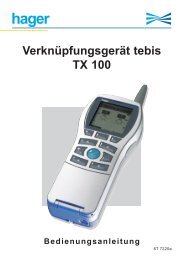
4.1 Inputs / Outputs<br />
The standard CM EIB application fills the complete LOGO!<br />
process image.<br />
A1 A2<br />
I1 I2 I3 I4 I5 I6 I7 I8<br />
LOGO! 12/24 RC<br />
CM-EIB/KNX<br />
Q1 Q2 Q3 Q4<br />
A3 ... A8<br />
I9 ... I24<br />
Q5 ... Q16<br />
Sensorik<br />
EIB (Instabus)<br />
Aktorik<br />
EIB<br />
I1 I2 I3 I4 I5 I6 I7 I8<br />
I9 I10 I11 I12<br />
230 RC DM8 AM2 CM EIB/KNX<br />
Q1 Q2 Q3 Q4 Q5 Q6 Q7 Q8 A 1 A2<br />
A3 ... A8<br />
I13 ... I24 Sensorik<br />
(Instabus)<br />
Q9 ... Q16 Aktorik<br />
CM EIB<br />
16 J31069-D1262-U002-A2-7618
CM EIB/KNX<br />
LOGO!<br />
I1 I2 I3 I4 I5 I6 I7 I8<br />
DM 8<br />
I9I10I11I12<br />
CM EIB/KNX<br />
1<br />
I9<br />
Q9<br />
2<br />
I1<br />
I14<br />
&<br />
Q16<br />
Q6<br />
3<br />
Q1<br />
I13<br />
Q1 Q2 Q3 Q4 Q5 Q6 Q7 Q8<br />
I13 ... I24<br />
Q9 ... Q16<br />
EIB (Instabus)<br />
1. To map the LOGO! inputs (I1 to I8/I12) as outputs on the<br />
EIB, these must be joined with free EIB outputs (Q5/Q9 to<br />
Q12) in the LOGO! application.<br />
2. Operations (basic functions BF / special functions SF)<br />
useable within the LOGO! application (e.g. as a feedback<br />
signal).<br />
3. To access the LOGO! application (Q1 to Q4/Q8) directly<br />
via the bus communications, these must be joined with<br />
free EIB inputs (I13 to I24) in the LOGO! application.<br />
CM EIB<br />
J31069-D1262-U002-A2-7618 17
CM EIB/KNX<br />
4.2 Available communication objects<br />
An example of the basic variant – LOGO! CPU and CM EIB<br />
without an expansion module:<br />
The following communication objects will be available on the<br />
EIB / KNX Bus:<br />
EIB-Object No. Type (Size) EIS IN / OUT<br />
0 UINT1 EIS1 I9 Input<br />
1 UINT1 EIS1 I10 Input<br />
2 UINT1 EIS1 I11 Input<br />
3 UINT1 EIS1 I12 Input<br />
4 UINT1 EIS1 I13 Input<br />
5 UINT1 EIS1 I14 Input<br />
6 UINT1 EIS1 I15 Input<br />
7 UINT1 EIS1 I16 Input<br />
8 UINT1 EIS1 I17 Input<br />
9 UINT1 EIS1 I18 Input<br />
10 UINT1 EIS1 I19 Input<br />
11 UINT1 EIS1 I20 Input<br />
12 UINT1 EIS1 I21 Input<br />
13 UINT1 EIS1 I22 Input<br />
14 UINT1 EIS1 I23 Input<br />
15 UINT1 EIS1 I24 Input<br />
16 UINT1 EIS1 Q5 Output<br />
17 UINT1 EIS1 Q6 Output<br />
18 UNIT1 EIS1 Q7 Output<br />
19 UINT1 EIS1 Q8 Output<br />
20 UINT1 EIS1 Q9 Output<br />
21 UINT1 EIS1 Q10 Output<br />
22 UINT1 EIS1 Q11 Output<br />
23 UINT1 EIS1 Q12 Output<br />
24 UINT1 EIS1 Q13 Output<br />
25 UINT1 EIS1 Q14 Output<br />
26 UINT1 EIS1 Q15 Output<br />
27 UINT1 EIS1 Q16 Output<br />
28 UINT16 / UINT8 EIS5 / EIS6 AI1 Input<br />
29 UINT16 / UINT8 EIS5 / EIS6 AI2 Input<br />
30 UINT16 / UINT8 EIS5 / EIS6 AI3 Input<br />
31 UINT16 / UINT8 EIS5 / EIS6 AI4 Input<br />
32 UINT16 / UINT8 EIS5 / EIS6 AI5 Input<br />
33 UINT16 / UINT8 EIS5 / EIS6 AI6 Input<br />
34 UINT16 / UINT8 EIS5 / EIS6 AI7 Input<br />
35 UINT16 / UINT8 EIS5 / EIS6 AI8 Input<br />
EIS1 (switches) 1 Bit<br />
EIS 5 (EIB floating) 2 byte value<br />
EIS 6 (EIB floating) 1 byte value<br />
CM EIB<br />
18 J31069-D1262-U002-A2-7618
CM EIB/KNX<br />
4.3 EIB configuration<br />
The following application parameters can be set in ETS2,<br />
V.1.2:<br />
- The number of digital I/Os on the LOGO! Master or<br />
expansion modules<br />
- The number of analog inputs on the LOGO! Master or<br />
expansion modules<br />
- The data type for each analog input EIS6 (scaling/8-bit<br />
with sign) or EIS5 (EIB-Value Temp/8-bit without sign).<br />
In the parameter dialog, you can set the number of inputs<br />
and outputs that are already on the LOGO! (including<br />
expansion modules) and how many are available via the EIB.<br />
CM EIB<br />
J31069-D1262-U002-A2-7618 19
CM EIB/KNX<br />
The EIS5 values are converted to a fixed point numerical<br />
value with a resolution of 0.1, which equates to a value range<br />
of –3276.8 (FFFFh) to +3276.7 (7FFFh).<br />
EIS6 values for scaling are accepted, i.e. 0 to 100 %<br />
corresponds to an analog value of 0 to 255.<br />
Unused analog inputs must be set to “Not Used”.<br />
CM EIB<br />
20 J31069-D1262-U002-A2-7618
CM EIB/KNX<br />
Inputs/Outputs – Special Considerations<br />
When using the LOGO! I/O on the CM EIB, you must<br />
consider the following.<br />
To access the LOGO! outputs (Q1 to Q4) directly via<br />
communication over the bus, these must be joined in the<br />
LOGO! application with free EIB inputs.<br />
To map the LOGO! inputs (I1 to I8) as outputs on the bus,<br />
these must be joined in the LOGO! application with free EIB<br />
outputs.<br />
The outputs on additional I/O modules can also be<br />
transferred in parallel via the EIB.<br />
CM EIB<br />
J31069-D1262-U002-A2-7618 21
CM EIB/KNX<br />
5 CM EIB - Specifications<br />
Electrical Data<br />
Supply voltage 24 V AC 24 V DC<br />
Permissible range -15% +10% -15% +20%<br />
Current consumption (power supply) max. 25 mA<br />
Current taken from BUS<br />
5 mA<br />
EIB data transfer rate<br />
9600 Baud<br />
Physical Construction<br />
Standard width<br />
Dimensions (W x H x D)<br />
Weight<br />
Mounting options<br />
Operational status display<br />
Controls<br />
2 SU<br />
36 x 90 x 55 mm<br />
approx. 50 g<br />
35 mm rail<br />
wall mounting<br />
RUN/STOP LED - communications<br />
with LOGO!<br />
BUS LED – communications with<br />
EIB/KNX<br />
EIB/KNX programming button S1<br />
Connections<br />
LOGO! connection<br />
EIB connection (TP 256)<br />
max. torque<br />
Power supply<br />
max. torque<br />
Standard bus lines to use<br />
Digital inputs (I) - virtual max. 16<br />
Digital outputs (Q) - virtual max. 12<br />
Analog inputs (AI) - virtual max. 8<br />
Max. group addresses 64<br />
Max. associations 64<br />
Standard expansion interface for<br />
LOGO! 12/24 V and 115/240 V<br />
2 screw terminals (0.5 – 2.5 mm²)<br />
0.5 Nm<br />
2 screw terminals (0.5 – 2.5 mm²)<br />
0.5 Nm<br />
YCYM or J-Y(ST)Y (2 x 2 x 0.8 mm²)<br />
Environmental Conditions<br />
Permissible operating temperature<br />
Storage and transport temperatures<br />
Humidity<br />
0°C to +55°C<br />
free convection<br />
-40°C to +70°C<br />
95% at +25°C<br />
CM EIB<br />
22 J31069-D1262-U002-A2-7618
CM EIB/KNX<br />
Safety<br />
Protection standard IP 20<br />
Radio interference suppression EN 55011 (Limit Value Class B)<br />
Certification<br />
CE<br />
EIB/KNX<br />
UL 508<br />
VDE 0631<br />
IEC 61131-2<br />
Overvoltage protection<br />
Fuse<br />
80 mA slow action fuse<br />
Order Data<br />
LOGO! Expansion Module<br />
EIB/KNX CM<br />
6BK1700-0BA00-0AA0<br />
CM EIB<br />
J31069-D1262-U002-A2-7618 23
CM EIB/KNX<br />
INDEX<br />
EIB<br />
EIS<br />
ETS<br />
KNX<br />
European Installation Bus<br />
EIB Interoperability Standard<br />
EIB Tool Software<br />
Standard of the Konnex Association<br />
CM EIB<br />
24 J31069-D1262-U002-A2-7618
Siemens Aktiengesellschaft<br />
Automation and Drives<br />
Systems Engineering<br />
PO. 2355, D-90713 Fürth<br />
www.siemens.com<br />
Order No. J31069-D1262-U002-A2-7618