
Marston Technical Catalogue - Safety Systems UK Ltd
Marston Technical Catalogue - Safety Systems UK Ltd
Marston Technical Catalogue - Safety Systems UK Ltd

You also want an ePaper? Increase the reach of your titles
YUMPU automatically turns print PDFs into web optimized ePapers that Google loves.
Pressure & Flame Protection<br />
Bursting Discs &<br />
Explosion Vent Panels
Bursting Discs &<br />
Explosion Vent Panels<br />
Bursting Discs - A bursting disc is a non-reclosing<br />
device that is designed to burst or rupture at a<br />
predetermined pressure, thus relieving a dangerous build<br />
up of pressure or vacuum, protecting plant, pipework or<br />
vessels from unacceptable levels of pressure or vacuum.<br />
Conventional Discs<br />
Often referred to as forward acting discs, ideal as a multipurpose<br />
and low cost solution.<br />
Reverse Buckling Discs<br />
These discs offer extended service life, particularly within<br />
pressure cycling duties. Ideal for relief valve protection.<br />
Graphite Discs<br />
Provide ideal low pressure protection for highly corrosive<br />
process media applications.<br />
Explosion Vent Panels - Designed to provide low<br />
pressure protection against the effects of dust or gas<br />
explosions. In the event of an explosion a correctly sized<br />
panel will open almost instantaneously to minimise the<br />
effects of the blast.<br />
1
The logical choice<br />
With over 50 years experience, <strong>Marston</strong> is a leading<br />
manufacturer of pressure relief and explosion<br />
protection devices known as bursting discs (or<br />
rupture discs) and explosion vent panels, providing<br />
safe and instantaneous relief in an ever increasing<br />
range of application requirements.<br />
The applications for these devices are as diverse as<br />
the industries that use them. Chemical, oil, gas and<br />
food as well as cryogenic and transportation are<br />
typical examples. The selection of the most suitable<br />
device can be critical, however our extensive range<br />
provides the optimum solution.<br />
To maintain our position at the forefront of disc and<br />
panel technology, we can call upon the wide range of<br />
technical resources available within <strong>Marston</strong>.<br />
These state-of-the-art facilities include:<br />
• High temperature testing<br />
• Helium leak testing<br />
• CAD/CAM<br />
• Pressure cycling<br />
• Radiographic inspection<br />
• Laser cutting technology<br />
• Flow test laboratory<br />
2
TESTING AND CERTIFICATION<br />
<strong>Marston</strong> bursting discs and explosion vent panels are<br />
batch tested in accordance with relevant British or<br />
other National and International standards and a test<br />
certificate is supplied for each batch of discs.<br />
If required by the customer, arrangements can be<br />
made for the batch test procedures to be witnessed<br />
by accredited external inspection authorities.<br />
All <strong>Marston</strong> explosion vent panels have been type<br />
tested under full explosion trials to prove their<br />
strength and reliability.<br />
<strong>Marston</strong>’s products carry a wide range of approvals<br />
and comply with the highest International standards<br />
and customer specifications, including:<br />
BS EN ISO 4126<br />
BS 2915<br />
A. D. 2000 Merkblatt A<br />
ASME Section VIII<br />
Stoomwezen<br />
Chinese <strong>Safety</strong> Quality Licence<br />
Other Accreditations include:<br />
PED 97/23/EC<br />
ATEX 94/9/EC<br />
BS EN ISO 9001<br />
Certificate Number Baseefa03ATEX0251 was also<br />
issued and all <strong>Marston</strong> Panels can now be CE-marked<br />
together with the protection coding reference<br />
xll 1 G D identifying their suitability for use in the<br />
most hazardous areas, Zone 0 and Zone 20.<br />
3<br />
Note:<br />
The performance of a bursting disc is dependant on its<br />
mounting arrangements. The use of discs in holders or<br />
mounting arrangements not approved by <strong>Marston</strong> will<br />
invalidate certification.<br />
QUALITY<br />
<strong>Marston</strong> is fully committed to a programme of total<br />
Quality Management which is focused on providing<br />
customer satisfaction and confidence. The concern<br />
with quality is evident at all levels within the<br />
organisation and has become an integral part of all<br />
processes.<br />
<strong>Marston</strong> maintains stringent control of design,<br />
development, testing and production to ensure that<br />
the highest quality standards are achieved in<br />
accordance with BS EN ISO 9001.<br />
A policy of continuous improvement and product<br />
development ensures that <strong>Marston</strong> is able to meet the<br />
demand for ever-increased safety protection.<br />
3
CONTENTS<br />
Page<br />
Bursting Discs<br />
5 Introduction<br />
6 Product Identification<br />
7-8 Product Range<br />
9 The Protection of <strong>Safety</strong> Valves<br />
10 Pressure and Temperature<br />
10 Pressure<br />
11 Temperature Ranges<br />
12 Vacuum/Reverse Pressure Supports<br />
13 Holders<br />
13 Holder Types<br />
14 Screwed, Welded and Adapter Type<br />
Assemblies<br />
15 Optional Features<br />
16 Location of Holder<br />
17 Flange Sealing<br />
18 Foolproofing Features<br />
19 Fugitive Emissions<br />
Page<br />
Explosion Vent Panels<br />
27-28 Introduction<br />
29 CSP and TSP<br />
30 Applications<br />
31 Pressure and Temperature<br />
31 Minimum Opening Pressure<br />
32 Frames<br />
32 Frames and Fitting<br />
33 Accessories<br />
33-34 Accessory Range<br />
35 Sizing and Selection<br />
35 Vent Sizing<br />
36 Enquiry Form<br />
37-38 Guide to Selection<br />
20 Accessories<br />
20 Excess Flow Valve<br />
21 Bursting Disc Indicators<br />
22 Break Wire Indicators<br />
23 Sizing and Selection<br />
23 Material Selection<br />
24 Enquiry Form<br />
25-26 Guide to Selection<br />
4
Bursting Discs<br />
INTRODUCTION<br />
All pressurised systems, conforming to the appropriate National and International standards, are limited to a<br />
maximum overpressure during pressure relief. In accordance with the EU Pressure Equipment Directive (P. E. D.),<br />
all pressure equipment defined therein must have a pressure relief or control system that limits the maximum<br />
overpressure to 1.1 x the maximum allowable design pressure of the equipment. A bursting disc safety device is<br />
a recommended means for pressure relief, and in some cases the preferred device. It is also used as the ultimate<br />
safety device should other pressure limiting equipment fail to function correctly. <strong>Marston</strong> bursting discs fulfil<br />
these requirements to protect the pressurised equipment.<br />
A bursting disc, often referred to as a rupture disc or a safety disc, is a non-reclosing pressure relief device.<br />
The resultant release of the contents from the protected system must be controlled in accordance with local,<br />
National and applicable EU/International rules and may necessitate the need for a fully contained relief system.<br />
The use of a correctly designed bursting disc device, its assembly and fitting is essential. Bursting disc devices<br />
are often fragile and need to be handled with care. They normally require a dedicated holder assembly.<br />
Bursting disc devices function due to the<br />
differential pressure applied across the disc.<br />
All pressures acting on the disc, including those<br />
induced by vent-side pressure, vacuum, system<br />
draining or cleaning, must be considered during<br />
specification.<br />
Choosing the most appropriate bursting disc<br />
device for a particular application depends on a<br />
number of key factors. This guide has been<br />
designed to assist the disc selection process.<br />
5
PRODUCT IDENTIFICATION<br />
Identification and traceability of the thousands of<br />
bursting discs and holders in use across the world<br />
today is critical.<br />
At <strong>Marston</strong>, every item carries a marking that can be<br />
traced back to its original manufacture.<br />
Each bursting disc device supplied by <strong>Marston</strong> is<br />
allocated a unique equipment number that provides<br />
exact identification.<br />
All details of manufacture (including material identity<br />
for each item supplied) are recorded and archived.<br />
Details can be tracked back over 40 years.<br />
Holder Label<br />
The equipment number is shown on the holder label,<br />
disc assembly tag and also on the test certificate that is<br />
supplied with each batch of discs.<br />
Following the original supply, subsequent batches of<br />
bursting discs add a suffix letter to the equipment<br />
number to provide batch identification.<br />
Example:<br />
Original supply :<br />
Holder ‘E’ No.NT 1234<br />
Bursting disc ‘E’ No.NT 1234<br />
(including reverse pressure support if required)<br />
First re-order<br />
of bursting discs ‘E’ No.NT 1234 / A<br />
Second re-order<br />
of bursting discs ‘E’ No.NT 1234 / B<br />
Note:<br />
The equipment number, together with an adequate<br />
description including bursting pressure and<br />
temperature, should be quoted for all replacement<br />
orders.<br />
Disc Tag<br />
6
PRODUCT RANGE - FORWARD ACTING BURSTING DISCS<br />
NT / NR Conventional Simple Domed<br />
Assemblies.<br />
The simplest of all discs, usually a single domed<br />
metallic foil which will probably fragment upon disc<br />
rupture.<br />
NTG / NRG Conventional Grooved Disc<br />
Assemblies.<br />
A single metallic foil which has grooved lines of<br />
weakness and is designed to be non-fragmenting.<br />
It will normally withstand vacuum conditions without<br />
the aid of a vacuum support.<br />
CS Composite Slotted Disc Assemblies<br />
A forward acting disc which has two membranes.<br />
A load-bearing slotted metallic outer membrane and a<br />
weaker, usually fluoropolymer, seal membrane giving a<br />
non-fragmenting design. This disc is widely used for<br />
lower bursting pressures.<br />
GR Graphite Discs<br />
A flat graphite disc, impregnated with a high quality<br />
resin, giving good corrosion resistance and low<br />
bursting pressures. The unique GR arrangement is<br />
designed to protect the disc from the effects of flange<br />
bolt loading. This disc fragments on rupture.<br />
Monobloc Graphite Discs<br />
A flat graphite disc, impregnated with a high quality<br />
resin, giving good corrosion resistance and low<br />
bursting pressures. This disc does not require a<br />
dedicated holder, and fragments on rupture.<br />
7
PRODUCT RANGE - REVERSE BUCKLING BURSTING DISCS<br />
MN / MO Maxivent Assemblies<br />
Usually a single foil disc which has the pressure applied<br />
to its convex side. The dome inverts and is completely<br />
expelled from its holder and stopped by an arrestor.<br />
RBH / RBF Assemblies<br />
Usually a single foil disc which has the pressure applied<br />
to its convex side. The dome inverts and opens along<br />
a peripheral groove. It is designed to be retained by its<br />
hinge portion.<br />
LRB / LRF Assemblies<br />
Usually a single foil disc which is designed specifically<br />
for liquid duties. The pressure is applied to its convex<br />
side. The dome inverts and opens along a peripheral<br />
groove. It is designed to be retained by its hinge<br />
portion.<br />
SRBH Assemblies<br />
This disc has two membranes. A load-bearing slotted<br />
metallic membrane and a weaker, usually<br />
fluoropolymer, seal membrane giving a nonfragmenting<br />
design suitable for low bursting pressures.<br />
RBX Assemblies<br />
A single metallic foil which has pressure applied to the<br />
convex side. The dome inverts and the disc opens<br />
along radial grooved lines. It is designed to retain all<br />
parts and withstand full vacuum without the aid of a<br />
vacuum support.<br />
GRB Graphite Disc Assemblies<br />
A unique disc manufactured from pure graphite<br />
powder. It is suitable for high temperatures and<br />
extremely low bursting pressures. This disc will<br />
fragment on rupture.<br />
8
THE PROTECTION OF SAFETY VALVES*<br />
<strong>Safety</strong> valve service life can be prolonged<br />
by using a bursting disc in series with the<br />
valve. The disc can be designed to be<br />
fitted at the inlet or at the outlet of the<br />
safety valve.<br />
Bursting discs are:<br />
1) Virtually leak free.<br />
2) Capable of preventing the process<br />
media attacking the internal parts of<br />
the safety valve, either by providing<br />
corrosion resistance or a physical<br />
barrier.<br />
3) Suitable for protecting the vent side<br />
of the safety valve from the ingress of<br />
moisture and associated debris from<br />
the vent system.<br />
Bursting discs are selected with a bore<br />
size suitable for the appropriate inlet or<br />
vent flange of the safety valve.<br />
The free vent area of the bursting disc<br />
used on the inlet side of the safety valve<br />
is always substantially greater than that<br />
of the valve.<br />
A number of international standards are<br />
available to allow the calculation of<br />
suitable bursting disc sizes.<br />
In all cases an excess flow valve is<br />
advised to prevent any pressure build up<br />
between the bursting disc and the safety<br />
valve.<br />
* <strong>Safety</strong> valves may also be referred to<br />
as relief valves or safety relief<br />
valves. Such valves are characterised by<br />
their ability to relieve excessive<br />
pressures at a pre-determined level and<br />
to re-seal once that pressure has been<br />
reduced to an acceptable, safe level. Such<br />
devices provide re-closing pressure relief<br />
and limit the quantity of product actually<br />
released.<br />
9
Pressure and Temperature<br />
GUIDE TO BURSTING PRESSURES<br />
Bursting pressure capabilities for each type of bursting<br />
disc vary depending on the design, size, material and<br />
temperature.<br />
Please consult one of our Sales Engineers for bursting<br />
pressures outside the ranges quoted in the table.<br />
MINIMUM / MAXIMUM BURSTING PRESSURES : Barg @ 20°C<br />
DISC TYPES<br />
BORE NT CS NTG MAXI RBH LRB SRBH RBX GR/G2 MONO GRB<br />
SIZE NR NRG VENT RBF LRF BLOC<br />
mm * * *<br />
25 0.8 1.5 4.0 12.4 1.8 3.0 1.2 18.9 1.0 1.0 0.4<br />
125 125 125 450 380 100 100 380 28.0 56 15<br />
40 0.6 1.0 2.6 7.0 1.2 2.5 0.9 13.1 0.52 0.5 —<br />
83 83 83 315 380 75 65 380 21.0 42 —<br />
50 0.4 0.75 2.0 5.5 0.9 2.0 0.6 10.3 0.275 0.4 0.14<br />
72 72 72 255 380 50 50 380 17.2 28 10<br />
65 0.35 0.65 3.4 4.8 0.8 1.75 0.5 9.6 0.24 0.4 —<br />
50 50 50 210 175 40 40 175 16.5 24 —<br />
80 0.3 0.5 2.5 3.4 0.7 1.5 0.4 6.9 0.21 0.3 0.1<br />
41 41 41 170 120 40 40 120 15.5 20 4.5<br />
100 0.2 0.35 1.9 3.0 0.6 1.4 0.3 5.5 0.14 0.2 0.04<br />
36 36 36 100 90 30 30 90 10.3 14 2.5<br />
150 0.14 0.3 1.4 2.0 0.5 1.25 0.25 3.8 0.07 0.2 0.04<br />
20 20 20 100 60 20 20 60 5.5 10.5 1.5<br />
200 0.1 0.25 1.4 1.7 0.5 1.25 0.2 2.8 0.07 0.1<br />
18 18 18 30 50 17.5 12.5 50 3.45 5.5<br />
250 0.1 0.2 1.4 1.7 0.5 1.25 0.2 2.25 0.07 0.1<br />
12.5 12.5 12.5 25 40 12 10 40 2.15 4.5<br />
300 0.07 0.2 1.4 1.7 0.5 1.25 0.2 0.02<br />
10 10 10 18 35 10 10 2.0<br />
350 0.07 0.15 1.4 1.7 0.5 1.25 0.2 0.02<br />
9.5 9.5 9.5 18 27.5 8.5 8.5 2.0<br />
400 0.07 0.12 1.4 1.4 0.5 1.25 0.2 0.02<br />
9 9 9 18 20 7.5 7.5 2.0<br />
450 0.07 0.10 1.4 1.0 0.5 1.25 0.2 0.02<br />
7 7 7 16 17 7 7.0 2.0<br />
500 0.07 0.07 1.4 1.0 0.5 1.25 0.2<br />
6 6 6 14 14 6.0 6.0<br />
550 0.07 0.07 - 1.0<br />
5.5 5.5 - 12<br />
600 0.07 0.10 - 0.8<br />
5 5 - 10<br />
750 0.07 0.10<br />
4 4<br />
* Maximum pressures are for standard designs, for higher pressures a welded construction is also available (see page 17).<br />
10
TEMPERATURE RANGES<br />
Materials for bursting discs have a limited allowable<br />
working temperature range.<br />
The table indicates the normal limits for commonly<br />
used bursting disc materials.<br />
The limitations of joint sealing materials must be<br />
considered as well as possible corrosion from the<br />
process or environmental conditions that prevail.<br />
MATERIAL -200°C -100°C 0°C 100°C 200°C 300°C 400°C 500°C 600°C<br />
ALUMINIUM<br />
NICKEL<br />
MONEL 400<br />
INCONEL 600<br />
HASTELLOY<br />
ST ST 316<br />
TANTALUM<br />
FEP<br />
When used as a<br />
PTFE<br />
corrosion protection<br />
membrane.<br />
PFA<br />
Impreg. GRAPHITE<br />
PURE GRAPHITE<br />
INFLUENCE OF TEMPERATURE<br />
Bursting disc materials are affected by changes to<br />
temperature. In general, higher temperatures induce a<br />
reduction of strength and consequently bursting<br />
pressure. The following graph shows the typical effect<br />
of temperature on various bursting disc materials for<br />
forward-acting discs:<br />
11<br />
Reverse buckling discs are generally less affected by<br />
temperature changes than equivalent forward acting<br />
discs. Each batch of reverse buckling discs will be<br />
affected differently, by factors other than just the<br />
material. A ‘typical’ temperature effect graph is<br />
therefore not considered to be helpful.<br />
Where operating conditions dictate its use, a heat<br />
shield can be fitted between the disc material and the<br />
process to provide a thermal barrier. This may be to<br />
preserve the disc integrity or to reduce heat loss.<br />
Teflon FEP and Teflon PFA are trade marks of the Dupont<br />
company.
VACUUM/REVERSE PRESSURE SUPPORTS<br />
Opening Type Vacuum Supports<br />
Many simple conventional discs and most composite<br />
slotted bursting discs are unable to withstand vacuum<br />
conditions without assistance.<br />
To allow them to be used for duties where vacuum is<br />
a possibility, even if only whilst equipment is being<br />
cleaned, a vacuum support can be fitted. Usually this<br />
takes the form of a multi-petal design Opening Type<br />
Support, which when the disc bursts, opens up to<br />
provide a large flow area.<br />
The Vacuum Support is permanently fixed to the<br />
bursting disc to ensure correct fitting. Therefore a<br />
new support does have to be supplied and fitted with<br />
each bursting disc.<br />
When calculating the disc size required, the Free Area<br />
through the support must always be considered.<br />
Auxiliary Support<br />
In some applications, reverse pressures may exist<br />
greater than atmospheric pressure. Often an Opening<br />
Type Support alone will be sufficient. However, sometimes<br />
an additional Auxiliary Support is required. This<br />
is designed to aid the opening support, whilst still<br />
maintaining a large free flow area. This type of support<br />
is often used in double disc assemblies, where a secondary<br />
disc is used to prevent an often variable<br />
reverse pressure from affecting the performance of<br />
the primary disc. This is common when several bursting<br />
discs vent into a common line or flare stack. This<br />
type of support is generally re-useable, with only the<br />
opening support needing to be replaced.<br />
Non-Opening Supports<br />
Some discs, particularly graphite, use a permanent or<br />
Non-Opening Type Vacuum Support. These supports<br />
are not usually attached to the disc but fit immediately<br />
upstream of the bursting disc, sometimes in a recess<br />
provided within the holder.<br />
These supports follow the form of the disc, whether it<br />
be flat or domed, and have holes through which the<br />
product flows when the disc bursts. These supports are<br />
considered to be re-useable and therefore only one is<br />
required for each position.<br />
More consideration must be given to the flow area for<br />
these supports as a typical free area through a<br />
permanent support is around 60%. See the relevant disc<br />
brochure for more details.<br />
Generally, reverse buckling discs do not require any<br />
additional support to withstand vacuum or reverse<br />
pressure.<br />
12
Holders<br />
HOLDER TYPES<br />
The bursting disc holder can have a significant effect<br />
on the performance of a bursting disc. The holder<br />
provides an accurate location, sealing face, vent bore<br />
size and form. Generally, holders will be<br />
manufactured from stainless steel, though other<br />
materials can be supplied when required. Holders<br />
are normally non-torque sensitive.<br />
Insert type<br />
<strong>Marston</strong> provide holders specifically designed for<br />
each disc type, and to fit the particular application.<br />
Usually the holder will be an insert type; one that fits<br />
within the flange bolt circle. This provides an easier<br />
method of fitting replacement bursting discs since<br />
fewer flange bolts need to be removed. Full face<br />
holders with flange bolt holes can be supplied if<br />
required.<br />
Full face type<br />
Holders usually consist of two annular rings that<br />
provide a flat sealing flange for the bursting disc.<br />
Consequently, the performance of the disc should be<br />
unaffected by excessive flange bolt loading. (Certain<br />
graphite assemblies require close control of the<br />
flange bolt torque.) Most holders are supplied with<br />
assembly screws. These can be simply to hold the<br />
assembly together whilst fitting onto the plant, or,<br />
for pre-torque type holders, they are tightened to<br />
pre-set values to ensure an adequate joint is<br />
achieved between the disc and holder before<br />
installing onto the plant. More details of both types<br />
of holders can be found in the individual product<br />
brochures.<br />
Pre-assembled holder<br />
Pre-torqued holder<br />
For sizes up to 250mm bore, the holder will usually<br />
provide dome protection. Larger sizes are often<br />
supplied without dome protection and where<br />
conditions allow, simple clamp rings may be<br />
acceptable. Where the bursting disc dome is not<br />
protected, extreme care must be taken when fitting<br />
to prevent damage.<br />
Protected dome<br />
Unprotected dome<br />
For large assemblies, where the holder weight<br />
exceeds 25kg, or where it is considered beneficial<br />
for handling purposes, <strong>Marston</strong> will make provision<br />
for suitable lifting attachments.<br />
Lifting eyebolt<br />
13
SCREWED, WELDED AND ADAPTOR TYPE ASSEMBLIES<br />
Where simple flanged joints are not practical,<br />
alternative designs are available. <strong>Marston</strong> have the<br />
experience and expertise to supply a wide variety of<br />
screwed assemblies and fully welded units, to satisfy<br />
the most arduous of requirements. These allow for<br />
screwing a disc holder unit into the main body of the<br />
pressurised vessel or for fitting directly into pipelines.<br />
Where it is practical, the discs may be scored so that<br />
they petal open.<br />
Various types are illustrated, with special designs<br />
prepared as required.<br />
TYPE<br />
AM<br />
A screwed adaptor as illustrated with male<br />
connection threads. Special designs are often<br />
manufactured to customer’s requirements.<br />
The standard pressure range is up to 700<br />
barg but higher pressures can be made to<br />
special order.<br />
AF<br />
A screwed adaptor as illustrated with female<br />
connection threads. Special designs are often<br />
manufactured to customer’s requirements.<br />
The standard pressure range is up to 700<br />
barg but higher pressures can be made to<br />
special order.<br />
WA<br />
A flanged type assembly suitable for<br />
applications up to 100 barg.<br />
TYPICAL<br />
CONNECTION<br />
1<br />
/4” to 1 1 /4” NPT / BSP<br />
1<br />
/4” to 1 1 /4” NPT / BSP<br />
Up to 6”/150mm NB.<br />
A flanged design for installing<br />
the disc close to the process.<br />
WA<br />
A plug type assembly suitable for applications<br />
up to 100 barg.<br />
1<br />
/4” to 1” BSP<br />
1<br />
/4” to 1“ NPT<br />
WA<br />
A stem type welded assembly for<br />
applications such as the protection of rubber<br />
or plastic extrusion presses. The disc is<br />
brazed or welded to the screwed stem<br />
1<br />
/2” UNF - standard<br />
Other sizes available<br />
LR<br />
A lens ring style bursting disc. This is<br />
another method of mounting a disc in high<br />
pressure pipework. It provides a leaktight<br />
seal at pressures up to 700 barg.<br />
3<br />
/8” to 2” NB<br />
8 to 50mm NB<br />
14
OPTIONAL FEATURES<br />
Pressure Tappings<br />
Tappings for monitoring equipment can be<br />
incorporated in the vent-side of the holder, or in the<br />
pressure-side if required. Any thread form and size is<br />
usually possible but this may in some cases require an<br />
increase in holder dimensions.<br />
Corrosion Protection<br />
For corrosive environments, holders manufactured<br />
from resistant materials may prove costly. One<br />
possible alternative offered by <strong>Marston</strong> is the Glass<br />
Filled-PTFE insert that also provides a non-stick<br />
surface. For extreme conditions a resistant metal<br />
liner such as nickel or tantalum may be suitable.<br />
Steam Heating<br />
Where the duty may be prone to polymerisation the<br />
holder can be heated. This can be achieved by<br />
introducing a chamber around the holder body and<br />
passing either hot water or steam through to prevent<br />
the product from cooling and solidifying.<br />
High Pressure<br />
When the bursting pressures exceed the limits for<br />
standard holder designs to retain the disc satisfactorily,<br />
alternative designs are available. Wedge type<br />
holders can be supplied on request but their performance<br />
can be affected by possible misalignment or<br />
incorrect torque of the plant flange bolts. For this<br />
reason, <strong>Marston</strong> would recommend the use of discs<br />
with welded edge rings for high pressures that fit into<br />
a simple recessed holder.<br />
15
LOCATION OF HOLDER BETWEEN FLANGES<br />
To ensure that the bursting disc holder is installed<br />
concentrically, each <strong>Marston</strong> bursting disc holder has<br />
an outside diameter manufactured specifically to suit<br />
its corresponding flange.<br />
Holder heights are available on request.<br />
TABLE OF OUTSIDE DIAMETERS<br />
Capsule Holders, to fit within the ring of flange bolts as shown above<br />
Flange Rating<br />
Holder Outside Diameter for Nominal Bores (mm)<br />
ANSI PN 25 40 50 65 80 100 150 200 250 300 350 400 450 500 600<br />
150 66 85 104 123 136 174 222 279 339 409 450 514 549 606 717<br />
10 73 94 109 129 144 164 220 275 330 380 440 491 - 596 698<br />
300 73 95 111 130 149 181 251 308 362 422<br />
16 73 94 109 129 144 164 220 275 331<br />
25 73 94 109 129 144 170 226 286 343<br />
600 73 95 111 130 149 194 266<br />
40 73 94 109 129 144 170 226<br />
900 79 98 143 165 168 205<br />
63/64 84 105 115 140 150 176<br />
1500 79 98 143 165 174<br />
100-164 84 105 121 146 156<br />
2500 85 117 146<br />
250 85 111 126<br />
16
FLANGE SEALING<br />
Bursting disc holders can usually be provided<br />
to satisfy the requirements of any type of<br />
flange sealing arrangement. The diagrams<br />
below illustrate typical examples. Flange joints<br />
(i.e. those between the holder and the mating<br />
flanges) will normally be provided by the<br />
customer. <strong>Marston</strong> will supply gaskets for<br />
bursting discs that are designed to be fitted<br />
directly between flanges, such as the<br />
Monobloc graphite disc.<br />
Flat gasket joint<br />
‘O’ ring joint for<br />
minimum leakage<br />
Ring type joint for high<br />
pressure/temperature<br />
Tongue and groove<br />
TABLE OF FACE TO FACE DIMENSIONS<br />
Bore Size<br />
TYPE 25 40 50 65 80 100 150 200 250 300 350 400 450 500 600<br />
Std 21 21 21 25 25 30 41 50 60 - - - - - -<br />
CST 1/4” NPT 30 30 30 30 30 30 41 50 60 - - - - - -<br />
1/2” NPT 38 38 38 38 38 38 42 50 60 - - - - - -<br />
Conn Head 42 42 42 42 42 42 46 50 60 - - - - - -<br />
Std 21 22 25 30 33 43 59 72 - - - - - - -<br />
NT 1/4” NPT 30 30 30 30 33 43 59 72 - - - - - - -<br />
1/2” NPT 38 38 38 38 38 43 59 72 - - - - - - -<br />
Conn Head 42 42 42 42 42 43 59 72 - - - - - - -<br />
Std 38 38 38 38 38 38 47 56 68 78 84 94 102 108 127<br />
CSB 1/4” NPT 46 46 46 46 46 46 46 56 68 78 84 94 102 108 127<br />
CSB-T 1/2” NPT 54 54 54 54 54 54 54 56 68 78 84 94 102 108 127<br />
Conn Head 58 58 58 58 58 58 58 58 68 78 84 94 102 108 127<br />
Std 26 27 28 30 30 32 43 55 70 85 100 110 125 135 -<br />
RBH 1/4” NPT 36 37 38 40 40 42 51 63 78 93 110 120 130 140 -<br />
RBH-T 1/2” NPT 48 49 50 52 52 54 63 75 90 105 118 128 138 148 -<br />
Conn Head 52 53 54 56 56 58 67 79 94 109 122 132 142 152 -<br />
Std 72 72 57 62 64 85 116 148 169 198 223 255 277 296 344<br />
MV-A 1/4” NPT 72 72 57 62 64 85 116 148 169 198 223 255 277 296 344<br />
1/2” NPT 72 72 57 62 64 85 116 148 169 198 223 255 277 296 344<br />
Conn Head 72 72 57 62 64 85 116 148 169 198 223 255 277 296 344<br />
Std 17 19 21 24 28 33 37 41 47 - - - - - -<br />
GR 1/4” NPT 33 35 37 39 42 45 48 52 57 - - - - - -<br />
1/2” NPT 41 43 45 47 50 53 56 60 65 - - - - - -<br />
Conn Head 45 47 49 51 54 57 60 64 69 - - - - - -<br />
Std 17 - 20 - 30 35 52 - - - - - - - -<br />
GRB 1/4” NPT 31 - 32 - 36 41 52 - - - - - - - -<br />
1/2” NPT 39 - 40 - 44 49 60 - - - - - - - -<br />
Conn Head 43 - 44 - 48 53 64 - - - - - - - -<br />
Monobloc Std 14 17 21 22 22 25 29 35 38 - - - - - -<br />
17<br />
Other sizes / options may be available. Please consult <strong>Marston</strong>.
FOOLPROOFING FEATURES<br />
A wrongly installed bursting disc can be disastrous.<br />
For this reason, where possible, <strong>Marston</strong> bursting disc<br />
assemblies are fitted with a foolproofing feature which<br />
is incorporated within the disc tag and holder identity<br />
label.<br />
<strong>Marston</strong> holders have a permanently attached stainless<br />
steel identity label. This uniquely identifies the holder<br />
type and equipment number. It also indicates the<br />
correct holder orientation relative to flow.<br />
The disc is fitted with a notched stainless steel tag as<br />
shown below. This uniquely identifies the disc type, its<br />
equipment number and batch, the rated bursting<br />
pressure and temperature, the design code and also<br />
indicates the vent side of the disc.<br />
The combination of the notched tag and the offset<br />
identity label, prevents the incorrect assembly of the<br />
disc to the holder.<br />
The holder can also be provided with installation<br />
inhibitors such as ‘J’ bolts. These prevent the holder<br />
from being installed incorrectly between the plant<br />
flanges. (See accessories on page 22 for details.) Other<br />
methods can be considered such as dowels, or tongue<br />
and groove flanges, to ensure correct installation.<br />
When these features are combined with <strong>Marston</strong><br />
comprehensive installation instructions, quick and<br />
simple installation is ensured.<br />
The photographs show the offset label on the holder<br />
and the notch on one side of the neck of the disc<br />
identification tag.<br />
These foolproofing features aid correct assembly and<br />
prevent incorrect assembly (as demonstrated in the<br />
two lower photographs).<br />
Offset label on Holder<br />
Notched Disc Tag<br />
Correct Assembly<br />
Incorrect Assembly<br />
18
FUGITIVE EMISSIONS: LEAK TIGHTNESS ACROSS DISC SEALING FLANGE<br />
FEATURES<br />
LEAK TIGHTNESS<br />
mbar.l/s<br />
Metal to metal joint 1 x 10 -4<br />
Gasket fitted to process side :<br />
G-9900 (Graphite-based ) 1 x 10 -4<br />
AFM 34 (Asbestos free ) 1 x 10 -4<br />
AFM 30 ( Asbestos free ) 1 x 10 -4<br />
PTFE 1 x 10 -4<br />
GYLON BLUE (PTFE) 1 x 10 -5<br />
‘O’ rings incorporated :<br />
PTFE 1 x 10 -6<br />
VITON 1 x 10 -6<br />
Silver-coated metal 1 x 10 -8<br />
Disc welded to holder<br />
ZERO<br />
Type MN : flat gasket :<br />
G-9900 ( Graphite based ) 1 x 10 -3<br />
AFM 34 (Asbestos free ) 1 x 10 -3<br />
PTFE / GYLON 1 x 10 -4<br />
Type MO : ‘O’ rings :<br />
PTFE 1 x 10 -4<br />
VITON 1 x 10 -6<br />
Silver coated metal 1 x 10 -8<br />
19
Accessories<br />
EXCESS FLOW VALVES<br />
Excess flow valves (EFV) may be fitted to prevent back<br />
pressure developing between a bursting disc and, for<br />
example, a safety relief valve during normal plant<br />
operation. The excess flow valves should be fitted in<br />
a horizontal mode. In the event of the disc rupturing,<br />
the excess flow valve will seal the vent system under<br />
the influence of the pressure pulse.<br />
EFV<br />
Standard Dimensions (BSP or NPT)<br />
M 1/4” 1/2”<br />
F 1/8” 1/4”<br />
Pressure Gauges<br />
Pressure gauges are normally supplied by the<br />
user, although <strong>Marston</strong> is able to supply them<br />
on request.<br />
Jack Screws<br />
To help users to separate the bursting disc<br />
holder from the system flanges during overhaul,<br />
or following an incident, jack-screws may be<br />
required. These are normally incorporated into<br />
pipe-flange drillings, although <strong>Marston</strong> can supply<br />
suitable screws if requested.<br />
‘J’ Bolt<br />
It is important that bursting disc assemblies are<br />
mounted in the correct orientation relative to the<br />
flow direction. Although the holder is stamped with a<br />
flow arrow, and the vent-side is also shown on the<br />
holder and disc labels, it is often a requirement that<br />
the installation is ‘foolproofed’. One such example is<br />
a ‘J’ bolt (as shown) which is welded to the holder and<br />
locates in a corresponding hole in one of the flanges.<br />
Other methods are also available.<br />
20
BURST DISC INDICATORS<br />
Once a bursting disc has ruptured, it is often beneficial<br />
to shut down relevant plant equipment as quickly as<br />
possible. One common method of achieving this is to<br />
fit a Burst Disc Indicator. A Burst Disc Indicator is a<br />
simple circuit, usually fitted downstream of the<br />
bursting disc. The signal is usually received in the<br />
plant control room. This then instigates the shutdown<br />
of the relevant equipment.<br />
Recognising industries need to minimise maintenance<br />
time, <strong>Marston</strong> now introduce the latest design in Burst<br />
Disc Indication.<br />
MAS (MAGNETIC ALARM SYSTEM)<br />
The <strong>Marston</strong> ‘MAS’ eliminates the need to disconnect<br />
the electrical supply to the rupture disc assembly,<br />
reducing changeover time.<br />
Magnet<br />
Sensor<br />
Retaining Screw<br />
A ‘sensor’ is located in the vent side of the assembly,<br />
retained by a screwed compression fitting. The hole<br />
into which the sensor fits does not pass through to<br />
the holder bore, therefore the sensor does not come<br />
into contact with the product contained in the vent<br />
line. Attached to the vent side of the disc is a small<br />
but powerful magnet. The magnetic field that it<br />
generates is detected by the sensor. When the disc<br />
ruptures, the magnetic field moves away and activates<br />
the sensor. This simple switching effect can be used to<br />
initiate an alarm or a programmed shutdown<br />
procedure.<br />
The <strong>Marston</strong> ‘MAS’ provides an integral, leak tight<br />
detector. The sensor, once fitted, does not need to be<br />
renewed when replacing the rupture disc. It can be<br />
unscrewed from the holder and replaced when the<br />
new disc is fitted. When the disc is replaced, the new<br />
disc includes a magnet already fitted which ensures<br />
that it will be installed in the correct position.<br />
MAS WITH CONNECTION HEAD<br />
Where an exposed cable is unfavourable, the ‘MAS’<br />
sensor is available with an integral connection head<br />
where the wires terminate inside the head which is<br />
rated IP68. The wires are never subjected to the often<br />
harsh environment of an industrial plant; instead, they<br />
pass through a connecting tube between the holder<br />
and the connection head via an ‘O’-Ring seal.<br />
Magnet<br />
Sensor<br />
‘O’-Ring<br />
Connection Pipe<br />
Connection Head<br />
21
BREAKWIRE INDICATORS<br />
<strong>Marston</strong> also manufactures break wire type Burst<br />
Indicators. Depending on their design they can either<br />
be fitted directly to the bursting disc or fitted<br />
‘remotely’ between the holder and the downstream<br />
pipe flange. This type can be fitted to existing disc<br />
assemblies or to safety relief valves.<br />
Both operate in the same fundamental manner; a small<br />
current passes around a normally closed circuit. When<br />
the disc activates the flow breaks the membrane<br />
carrying the circuit which causes the current to be<br />
interrupted, indicating disc failure.<br />
DIRECT MOUNTED INDICATORS<br />
The direct mounted type has the circuit, or ‘Indicator<br />
Loop’, fixed to the disc. The attached wires then pass<br />
through the vent side holder, along a connection pipe<br />
and connect to pins on a pressure tight, feed through<br />
seal. Short wires on the other side of the seal then<br />
terminate in the connection head.<br />
Burst Disc Indicator fitted<br />
directly to vent side of the disc.<br />
REMOTE INDICATORS<br />
The ‘remote’ burst disc indicator has the circuit fixed<br />
to a membrane and is used on the downstream side of<br />
the holder, replacing the usual gasket. The remote<br />
design is not only available for new installations but<br />
can also be fitted to existing equipment and can even<br />
be used downstream of safety relief valves. Note that<br />
remote burst indicators are not suitable for use with<br />
Ring Type Joints or Tongue and Groove flange faces.<br />
There are two types of remote burst indicator, the<br />
traditional plastic membrane or a more robust metal<br />
design. The metal design allows the use of corrosion<br />
resistant metals which permit their use at higher<br />
temperatures.<br />
Both of the ‘remote’ designs are available with a<br />
connector mounted directly onto the unit with its<br />
mating part fitted to a flying lead for permanent<br />
installation into the plant. The wiring does not<br />
therefore need to be disconnected from the plant*<br />
when changing the burst indicator, simply unplug the<br />
connector, fit a new burst indicator, and reconnect<br />
the plug.<br />
*Subject to plant and other local regulations and isolating<br />
the feed if required.<br />
Burst Disc Indicator<br />
for remote fitting<br />
between holder and<br />
vent side flange.<br />
All <strong>Marston</strong> Burst Disc Indicators have been approved<br />
to II 1 GD 85°C EEx ia IIC T6 (-35°C ≤ Ta ≤ +75°C);<br />
i.e. they do not induce or release sufficient electrical<br />
energy when they function to cause an explosion even<br />
in the most hazardous environment, Zone 0.<br />
The system requires a 100mA maximum supply feed<br />
from an appropriate isolator barrier.<br />
Note:<br />
When a Zener barrier is used, the holder must be earthed<br />
to inhibit high circulating currents.<br />
Burst Disc Indicators are components which have been<br />
considered NOT to require EMC testing on their own. It is<br />
the users responsibility to ensure compliance with the EMC<br />
Directive in relation to their particular system.<br />
22
Sizing and Selection<br />
MATERIAL SELECTION<br />
Materials will normally conform to those listed below.<br />
Other materials are also available.<br />
DISC/VACUUM SUPPORT MATERIAL<br />
Material Name Number ASME / ASTM UNS No<br />
*St.St.316 X5CrNiMo 17 12 2 1.4401 SA / A240 - 316 S31600<br />
*St.St.316L X3CrNiMo 17 13 3 1.4436 SA / A240 - 316L S31603<br />
St.St.321 X6CrNiTi 18 10 1.4541 SA / A240 - 321 S32100<br />
*Nickel 200 NA 11 2.4060 SB / B162 - N02200 N02200<br />
*Monel 400 NA 13 2.4360 SB / B127 - N04400 N04400<br />
*Inconel 600 2.4816 SB / B168 - N06600 N06600<br />
Inconel 625 2.4856 SB / B443 - N06625 N06625<br />
*Hastelloy C276 2.4602 SB / B575 - N10276 N10276<br />
*Tantalum B708 - R05200 R05200<br />
Titanium Gr1 3.7025 SB / B265 - R50250 R50250<br />
EN ISO 4126-2, Annex A, provides a list of all the recommended metallic foils for bursting discs.<br />
Non-metalic foils include Graphite, Teflon-PFA and PTFE.<br />
Note: Teflon FEP and Teflon PFA are trade marks of the Dupont Company<br />
HOLDER MATERIAL<br />
Material Name Number ASME / ASTM UNS No<br />
Carbon Steel BS 3146-1 1.0037 SA / A105 K03504<br />
SS 304 X5CrNi 18 10 1.4301 SA / A479 - 304 S30400<br />
SA / A182 - 304<br />
SS 316 X5CrNiMo 17 12 2 1.4401 SA / A479 - 316 S31600<br />
SA / A182 - 316<br />
*SS 316L X3CrNiMo 17 13 3 1.4436 SA / A479 - 316L S31603<br />
SA / A182 - 316L<br />
SS 321 X6CrNiTi 18 10 1.4541 SA / A479 - 321 S32100<br />
SA / A182 - 321<br />
Super Austenitic 254SMo 1.4547 SA / A479 - S31254 S31254<br />
SA / A182 - S31254<br />
Duplex 22Cr5NiMo 1.4462 SA / A479 - S31803 S31803<br />
SA / A182 - S31803<br />
Nickel 200 NA 11 2.4060 SB / B160 - N02200 N02200<br />
Monel 400 NA 13 2.4360 SB / B164 - N04400 N04400<br />
Inconel 600 2.4816 SB / B166 - N06600 N06600<br />
Inconel 625 2.4856 SB / B446 - N06625 N06625<br />
Hastelloy C276 2.4602 SB / B574 - N10276 N10276<br />
Tantalum B708 - R05200 R05200<br />
Titanium Gr1 3.7025 SB / B348 - R50250 R50250<br />
EN ISO 4126-2, Annex B, provides a list of all the recommended metallic materials for bursting disc holders.<br />
ASME Section 2 details holder material requirements for ASME UD certified bursting discs<br />
*Denotes standard materials.<br />
23<br />
GASKET MATERIAL<br />
The table lists the common jointing materials<br />
(as shown on page 19), detailing the maximum<br />
pressures and temperatures at which they can be used.<br />
TYPE Material Maximum Maximum<br />
Pressure (@20°C) Temperature<br />
FLAT GASKET AFM 34 100 Bar 250°C<br />
AFM 30 100 Bar 200°C<br />
G-9900 138 Bar 550°C<br />
Gylon Blue 55 Bar 250°C<br />
PTFE 55 Bar 250°C<br />
‘O’ RING Viton 250 Bar 150°C<br />
PTFE 350 Bar 250°C<br />
Silver Plated St.St. 1000 Bar 600°C
Wobaston Road, Fordhouses,<br />
Wolverhampton WW10 6QJ, England<br />
Telephone +44 (0)1902 623550<br />
Facsimile +44 (0)1902 623555<br />
Email marston@safetysystemsuk.com<br />
Web www.safetysystemsuk.com<br />
To enable <strong>Marston</strong> to supply the optimum Bursting<br />
Disc Device, certain basic information is essential.<br />
Photocopy this page, completing as much information<br />
as possible and forward to the contact details above.<br />
A size and select CD programme is also available on<br />
request. This allows the user to perform sizing and<br />
capacity calculations in accordance with selected<br />
international standards.<br />
Company Name:<br />
Reference:<br />
Contact Name: Telephone: Fax:<br />
Tag Number<br />
Service conditions Upstream of Disc<br />
Medium in contact with disc<br />
Gas / Liquid / Vapour MW / SG cp/cv / Visc<br />
Risk of polymerisation<br />
Normal maximum operating pressure & temperature<br />
Vacuum conditions<br />
Pressure pulsations / Cycling: Give details<br />
Service conditions Downstream of Disc<br />
Medium in contact with disc<br />
Gas / Liquid / Vapour<br />
Normal operating pressure & temperature<br />
Maximum operating pressure & temperature<br />
Vacuum conditions<br />
Installation<br />
Nominal size (or mass flow rate)<br />
Flange standard / facing<br />
Bursting pressure<br />
Temperature at bursting pressure<br />
Sole relieving device / u/s of safety relief valve<br />
Is tapping required If yes give size<br />
Acceptable disc materials<br />
Acceptable holder materials - upstream<br />
Acceptable holder materials - downstream<br />
Vessel / pipe material<br />
Flange gaskets - type & material<br />
Is fragmentation allowed<br />
Design pressure<br />
Design code<br />
Accessories<br />
Burst disc indicator Y/N<br />
Excess flow gauge Y/N<br />
Pressure gauge Y/N<br />
Flange bolts Y/N<br />
Jack screws Y/N<br />
Any other relevant information / sketch<br />
Use additional sheet if necessary<br />
Quantities<br />
Discs<br />
Holders<br />
24
25<br />
GUIDE TO BURSTING DISC SELECTION<br />
The following information is presented as an aid to bursting disc selection. It will guide the<br />
user through certain criteria to give a general assessment of the choice of bursting disc for<br />
a particular application. It will help to<br />
eliminate those which are unsuitable for<br />
specific reasons<br />
APPLICATIONS<br />
1<br />
Simple application<br />
where a disc is the<br />
primary safety device<br />
on a pressurised<br />
system<br />
2<br />
Simple application<br />
where a disc is the<br />
primary safety device.<br />
Negative pressure<br />
may require a reverse<br />
pressure support.<br />
3<br />
Two discs mounted<br />
in parallel with<br />
interlocked valves<br />
enabling rapid<br />
changeover from a<br />
ruptured disc to a<br />
second disc.<br />
4<br />
Two discs mounted<br />
in series. Used where<br />
process media is<br />
likely to attack a disc<br />
material.<br />
5<br />
A disc used as a<br />
secondary safety<br />
device. In the event<br />
of safety valve failure<br />
to vent, the disc<br />
provides the ultimate<br />
protection.<br />
6<br />
A disc used to<br />
protect a safety valve.<br />
Essential in some<br />
corrosive or viscous<br />
applications.<br />
7<br />
Where corrosion<br />
could attack the<br />
ventside of a safety<br />
valve, discs may be<br />
employed as a<br />
protection.<br />
8<br />
Two discs mounted<br />
in series. Used where<br />
multiple relief<br />
streams vent into a<br />
common manifold.<br />
FORWARD ACTING BURSTING DISCS<br />
REVERSE BUCKLING BURSTING DISCS<br />
NT/NR<br />
NTG/NRG<br />
CS<br />
LPCS<br />
GR/G2<br />
MONO<br />
BLOC<br />
MN/MO<br />
RBH/<br />
RBF<br />
LRB/<br />
LRF<br />
SRBH<br />
RBX<br />
GRB<br />
(i) Under certain conditions a Vacuum or<br />
Reverse Pressure Support may be required.<br />
This depends on the disc size, material and<br />
rating. Refer to the individual Product<br />
Brochure for more detailed information.<br />
Applications<br />
1 2 3<br />
4 5<br />
7 8<br />
1 2 3<br />
4 5<br />
6 7 8<br />
1 2 3<br />
4 5<br />
6 7 8<br />
1 2 3<br />
4 5<br />
6 7 8<br />
1 2 3<br />
4 5<br />
7<br />
1 2 3<br />
4 5<br />
7<br />
1 2 3<br />
4 5<br />
6 7 8<br />
1 2 3<br />
4 5<br />
6 7 8<br />
1 2 3<br />
4 5<br />
6 7 8<br />
1 2 3<br />
4 5<br />
6 7 8<br />
1 2 3<br />
4 5<br />
6 7 8<br />
1 2 3<br />
4 5<br />
7<br />
ASME<br />
VIII<br />
Kr<br />
–<br />
0.6<br />
0.4 / 1.2<br />
–<br />
–<br />
–<br />
–<br />
0.5 / 1.0<br />
1.0<br />
–<br />
1.0<br />
(ii)The Operating or Working Ratio is the ratio of the<br />
Working Pressure to the minimum tolerance Burst<br />
Pressure. Reverse Buckling discs can offer a higher<br />
capability than Conventional Tensile-loaded discs.This ratio<br />
can be affected by disc material and operating temperature.<br />
–
Pressure<br />
Range<br />
Bar g<br />
Size<br />
Range<br />
NB<br />
mm<br />
Relief<br />
Phase<br />
Gas/Liquid<br />
SRV<br />
Isolation<br />
Support<br />
Required for<br />
Vacuum<br />
Duty (i)<br />
Leak<br />
Tightness<br />
mbar. l/s<br />
@ 20°C<br />
Operating<br />
Pressure<br />
Ratio @ 20°C<br />
(ii)<br />
Fragmentation<br />
(iii)<br />
Pulsating<br />
Pressure<br />
Capability<br />
(iv)<br />
0.3<br />
to<br />
1030<br />
3<br />
to<br />
1200<br />
✗<br />
Generally<br />
1 x 10 -6 0.75<br />
Required<br />
0.3<br />
to<br />
1030<br />
25<br />
to<br />
800<br />
NOT<br />
Required<br />
1 x 10 -6<br />
0.80<br />
0.07<br />
to<br />
125<br />
25<br />
to<br />
1100<br />
Required<br />
1 x 10 -3<br />
0.80<br />
0.08<br />
to<br />
10<br />
25<br />
to<br />
300<br />
Required<br />
1 x 10 -3<br />
0.50<br />
0.07<br />
to<br />
28.0<br />
25<br />
to<br />
450<br />
✗<br />
Required<br />
where<br />
Pb
Explosion Vent Panels<br />
INTRODUCTION<br />
The occurrence normally called<br />
an explosion is more accurately<br />
referred to as a deflagration.<br />
This is the rapid burning of a<br />
mixture of dust or gas within<br />
an oxygen-rich atmosphere<br />
(typically air) leading to a very<br />
rapid pressure rise inside the<br />
vessel or system. Unless this<br />
pressure is relieved the vessel<br />
or system can be ruptured,<br />
causing the products of the<br />
rapid combustion to be<br />
released uncontrollably.<br />
Pmax –<br />
Pred –<br />
Pstat –<br />
This results in the devastating effect referred to as an explosion, causing widespread damage to plant and<br />
personnel.<br />
Operators of plant handling flammable gases are well aware of the dangers of explosions and the need for<br />
continual care and attention to prevent ignition. Perhaps less well known is that there is a similar risk when<br />
handling materials that produce dusty conditions, such as foodstuffs, grain, sugar, coal and some plastics and<br />
metals. Where dusts can be present and suspended in the atmosphere, then an equally disastrous explosion can<br />
occur if the mixture is ignited.<br />
Time<br />
Pmax<br />
Pred<br />
Pstat<br />
Maximum pressure generated<br />
during an unvented explosion<br />
Reduced explosion pressure<br />
generated as a result of fitting<br />
a venting device<br />
Static opening pressure of the<br />
venting device<br />
The severity of an explosion can be affected by a number of factors, which are often inter-related.<br />
The damage that an explosion can cause is directly related to the pressure that can be generated. This pressure<br />
is affected by the individual characteristics of the dust or gas, the volume and geometry of the vessel being<br />
operated and the strength or ‘rupture pressure’ of the weakest section of the vessel.<br />
Dusts and gases burning uncontrollably within a vessel can rapidly generate pressures up to<br />
10 Barg (145 Psig) or higher. Unless the vessel is sufficiently strong this high pressure will cause the vessel to<br />
deform or even rupture at its weakest point. Where such vessels are long and relatively narrow the weak point<br />
could be the end-cap. The resultant explosion could induce a fierce jet effect.<br />
A correctly sized and fitted explosion vent panel, or group of panels, will help to reduce the likelihood of major<br />
damage to the vessel and anything nearby.<br />
The vent panel will open at a low pressure and allow the pressure to be released.<br />
The vent area is dependent on the geometry of the equipment being protected. Elongated equipment can<br />
develop very high pressure as a result of ‘pressure piling’, resulting in detonations if the explosion is incorrectly<br />
vented.<br />
Care must be exercised when considering venting, in particular the safe siting of the vent panel. In the event of<br />
an explosion, flame, product (both burnt and unburnt) and pressure waves will result.<br />
The equipment being protected will also need to be capable of withstanding the internal pressure and any<br />
resulting reaction forces due to the venting process.<br />
Often, protected equipment will be located indoors, in areas where it is impractical or unsafe to vent. In these<br />
instances it may be possible to vent the explosion through an outside wall, via a duct. The duct should be as<br />
short and straight as possible to minimise its effects on the venting process. A vent may need to be considerably<br />
larger if a duct is used.<br />
27
Who is at Risk<br />
Many industries are at risk of an explosion. The more common ones are:<br />
• Paper<br />
• Pharmaceutical<br />
• Food<br />
• Wood<br />
• Aggregates<br />
• Plastics<br />
• Metal fines<br />
In addition, bulk-handling systems in any industry may be at risk. Equipment such as Blenders, Dryers Cyclones<br />
and Mills are the source of many explosions, not forgetting Filters and Silos, which together account for almost<br />
half of reported explosions. Consideration must also be given to connecting equipment. Conveyors, Ducts and<br />
Elevators are common sources of explosions. Interconnected equipment must be given special attention as an<br />
explosion propagating from one piece of equipment to another can cause even more devastation than one in<br />
isolation.<br />
The ignition can originate from many sources, such as sparks, friction, mechanical failures, flames or even static.<br />
It is very often impossible to eliminate every ignition source, or prevent completely the risk of an explosion.<br />
Therefore venting is probably the most economical form of protection for your plant.<br />
The Solution<br />
Explosion vent panels provide an economical method of minimising the effects of an explosion.<br />
When equipment is unvented, high pressure can quickly be generated. In many cases this pressure is sufficient to<br />
cause permanent and sometimes catastrophic damage.<br />
<strong>Marston</strong> explosion vent panels are a recognised and effective solution. These panels are of a lightweight<br />
construction and are designed to open and vent, providing almost instantaneous relief at low pressures, typically<br />
0.1 Bar (1.5 Psig). Care must be exercised when siting the vent to ensure that the products of any resulting<br />
explosion are directed to a safe location, minimising the risk of damage or injury.<br />
<strong>Marston</strong> explosion vent panels provide a fully certified,<br />
reliable, maintenance free solution to the problem of<br />
explosion venting. They are designed to be nonfragmenting<br />
and are simple to install on both new and<br />
existing equipment.<br />
28
CSP EXPLOSION VENT PANELS<br />
The CSP type explosion vent panel is a traditional<br />
composite slotted design.<br />
The opening pressure is controlled by the slotted<br />
metal membrane, whilst the system integrity is<br />
provided by the seal membrane, usually manufactured<br />
from Teflon.<br />
Primarily this type of vent is flat, but it can just as<br />
easily be domed to suit operating conditions.<br />
Under steady conditions, flat panels may operate at up<br />
to 50% of the minimum activation pressure, whilst<br />
domed panels may operate at up to 70%. Neither is<br />
suitable for vacuum conditions, unless a support is<br />
fitted.<br />
This design of panel provides accurate, cost effective<br />
explosion protection on equipment generally<br />
operating at, or near to atmospheric conditions.<br />
TSP EXPLOSION VENT PANELS<br />
The TSP type explosion vent panel<br />
moves one step further from the CSP<br />
type with the addition of a second<br />
slotted membrane on the process side.<br />
This gives the panel some resistance to<br />
vacuum without adding a support. It<br />
also protects the delicate Teflon seal<br />
membrane from abrasion.<br />
Vent side frame<br />
Slotted Membrane<br />
Like the CSP membrane this too can<br />
be flat or domed and can be provided<br />
with additional support where higher<br />
vacuum conditions prevail.<br />
A flat TSP explosion vent panel will<br />
withstand pressures of up to 25% of its<br />
minimum pressure, in both directions.<br />
Domed panels will withstand 40% of<br />
their activation pressure, but generally<br />
no vacuum. In the event of greater<br />
levels of vacuum a support can<br />
generally be fitted.<br />
Seal Membrane<br />
Process Side Membrane<br />
(TSP only)<br />
Gasket<br />
Process Side Frame<br />
Mesh Support<br />
(Where required)<br />
29
APPLICATIONS<br />
Explosion vent panels can be used for almost any<br />
application where explosion relief is required. This<br />
could range from a simple storage silo to a<br />
complicated processing system. Each application<br />
requires individual appraisal and consideration to<br />
ensure that the correct venting device is employed.<br />
Some of the more common equipment where venting<br />
may be required is discussed in the following<br />
paragraphs, along with some of the special<br />
considerations that need to be addressed.<br />
Silos<br />
A silo as an individual piece of equipment poses no<br />
real problems although any ancillary equipment<br />
associated with them may. The only real concern in<br />
many cases is the length to diameter ratio discussed in<br />
the sizing section. Often silos are long and as a result<br />
require large vent areas to protect them.<br />
Filters/Separators<br />
Explosion vents should always be located on the dirty<br />
side of the filter elements, and in a position that is not<br />
obstructed by the filter units. When determining the<br />
volume being protected, consideration should be given<br />
to the effect of any explosion on the filter units.<br />
Will they collapse or burn, resulting in a much larger<br />
volume than first estimated<br />
Elevators/Conveyors<br />
Long, small section equipment needs to be approached<br />
in a different way to that detailed on pages 5 and 6.<br />
It is common to fit vents of a size equal to the cross<br />
section of the equipment at regular intervals. Contact<br />
<strong>Marston</strong> for more assistance.<br />
Mills/Grinders<br />
Often mills and grinders are built strong enough so<br />
that they will withstand a deflagration. If venting is<br />
required, special attention needs to be given to<br />
vibration and its effect on a relatively weak venting<br />
device.<br />
Interconnected Equipment<br />
Greater care must be taken when considering<br />
explosion protection in one piece of equipment that is<br />
linked to another. The ensuing explosion, which<br />
occurs as a result of an explosion propagating from<br />
another source, can be far more violent than an<br />
isolated incident. Vent areas may need to be doubled<br />
to provide satisfactory relief. Contact <strong>Marston</strong> for<br />
further assistance.<br />
Cyclones<br />
Cyclones require smooth internal surfaces to allow<br />
them to work effectively. Often, due to their relatively<br />
weak construction, it is not possible to fit sufficient<br />
vent area onto the flat, top face of the vortex. In this<br />
case, consideration should be given to a curved panel<br />
which can be designed to follow the shape of the<br />
cylinder.<br />
Dryers<br />
Spray dryers in particular tend to have large volumes,<br />
which in turn require large vent areas. The explosion<br />
vent may then become a major source of heat loss,<br />
reducing the dryer’s efficiency. Panel selection should<br />
be made with this in mind, using a heat shield to<br />
reduce the heat loss where necessary.<br />
30
Pressure and Temperature<br />
MINIMUM OPENING PRESSURES<br />
CSP<br />
Nominal Diameter/Minimum Opening Length<br />
Units<br />
Seal Material mm 250 300 350 400 500 600 750 1000 1200 Max<br />
(ins) (10) (12) (14) (16) (20) (24) (30) (40) (48) Temp<br />
FEP/PFA Barg 0.16 0.16 0.12 0.12 0.08 0.05 0.05 0.05 0.05 200°C<br />
(Psig) (2.4) (2.4) (1.8) (1.8) (1.2) (0.75) (0.75) (0.75) (0.75) (390°F)<br />
PTFE Barg 0.2 0.2 0.15 0.15 0.1 0.07 0.07 0.07 0.07 250°C<br />
(Psig) (2.9) (2.9) (2.2) (2.2) (1.5) (1.0) (1.0) (1.0) (1.0) (480°F)<br />
Aluminium Barg 0.3 0.3 0.3 0.3 0.3 0.3 0.3 – – 425°C<br />
(Psig) (4.4) (4.4) (4.4) (4.4) (4.4) (4.4) (4.4) – – (800°F)<br />
Note: If a Heat Shield is used it may be possible to use at higher temperatures. See Accessories section.<br />
TSP<br />
Nominal Diameter/Minimum Opening Length<br />
Units<br />
Seal Material mm 250 300 350 400 500 600 750 1000 1200 Max<br />
(ins) (10) (12) (14) (16) (20) (24) (30) (40) (48) Temp<br />
FEP/PFA Barg 0.25 0.25 0.2 0.2 0.15 0.1 0.1 0.07 0.07 200°C<br />
(Psig) (3.6) (3.6) (2.9) (2.9) (2.2) (1.5) (1.5) (1.0) (1.0) (390°F)<br />
PTFE Barg 0.3 0.3 0.25 0.25 0.18 0.1 0.1 0.08 0.08 250°C<br />
(Psig) (4.4) (4.4) (3.6) (3.6) (2.6) (1.5) (1.5) (1.2) (1.2) (480°F)<br />
Aluminium Barg 0.4 0.4 0.4 0.4 0.4 0.4 0.4 – – 425°C<br />
(Psig) (5.8) (5.8) (5.8) (5.8) (5.8) (5.8) (5.8) – – (800°F)<br />
Note: If a Heat Shield is used it may be possible to use at higher temperatures. See Accessories section.<br />
PTX<br />
Panel Size Reference<br />
Material Units 645. 710. 645. 710. 920. 1000. 920. 1000. 1000. Max<br />
365 450 645 710 586 710 920 920 1000 Temp<br />
Stainless Steel Barg 0.1 0.1 0.05 0.05 0.05 0.05 0.07 0.07 0.07 300°C<br />
(Psig) (1.5) (1.5) (0.75) (0.75) (0.75) (0.75) (1.0) (1.0) (1.0) (570°F)<br />
Nickel Barg 0.1 0.1 0.05 0.05 0.05 0.05 – – – 400°C<br />
(Psig) (1.5) (1.5) (0.75) (0.75) (0.75) (0.75) – – – (750°F)<br />
Inconel Barg 0.1 0.1 0.07 0.07 0.07 0.07 – – – 550°C<br />
(Psig) (1.5) (1.5) (1.0) (1.0) (1.0) (1.0) – – – (1020°F)<br />
Aluminium Barg 0.07 0.07 0.05 0.05 0.05 0.05 0.05 0.05 0.05 100°C<br />
(Psig) (1.0) (1.0) (0.75) (0.75) (0.75) (0.75) (0.75) (0.75) (0.75) (212°F)<br />
Note: If a Heat Shield is used it may be possible to use at higher temperatures. See Accessories section.<br />
<strong>Marston</strong> explosion vent panels can meet or exceed the advisory limits recommended in the<br />
various codes and guides. For details or to discuss pressure requirements below the limits<br />
set out above, the engineer, contractor or user should contact the factory direct.<br />
31<br />
Tolerances<br />
The table opposite lists tolerances for <strong>Marston</strong><br />
explosion vent panels when used in a <strong>Marston</strong><br />
approved frame. In some instances it may be<br />
necessary to increase tolerances where the frame<br />
is not in accordance with <strong>Marston</strong> limits.<br />
Activation Pressure CSP TSP PTX<br />
< 0.07 Barg ( 0.3 Barg (>4.3 Psig) ±20% ±20% ±15%
W<br />
w<br />
Frames<br />
FRAMES AND FITTING<br />
<strong>Marston</strong> explosion vent panels are usually mounted<br />
into a bolted frame to enable them to be fitted onto<br />
the equipment they are protecting. Using a frame<br />
guarantees the opening size and therefore the<br />
accuracy of the opening pressure. They also ease the<br />
installation procedure in many cases. The frame<br />
section employed by <strong>Marston</strong> is generally flat which<br />
allows the user to bolt directly to the protected<br />
equipment and allows the simple connection of<br />
downstream ducting. The frames can be supplied with<br />
either the <strong>Marston</strong> recommended hole configuration,<br />
or to suit the clients own or existing arrangement.<br />
In some instances, the frames may be fitted with a<br />
support grid or mesh. This can be to prevent<br />
implosion of a membrane or to prevent injury to<br />
personnel falling through. Implosion may be as a result<br />
of a vacuum condition during normal operation or<br />
cleaning, or it could be a reverse pressure such as<br />
wind loading. Whatever the reason, any restriction<br />
must be taken into account when establishing the<br />
required vent area.<br />
Generally frames are constructed from either Stainless<br />
Steel or Carbon Steel, although it is possible for other<br />
materials to be considered.<br />
<strong>Marston</strong> are always ready to provide a custom<br />
designed solution to satisfy the individual needs of the<br />
customer. This can involve differing shapes and sizes,<br />
rectangular, circular, semi-circular, trapezoidal,<br />
triangular and even curved panels are just some of the<br />
shapes available.<br />
We also appreciate the need to provide the user with<br />
a readily available, standard solution.<br />
MARSTON RANGE OF STANDARD FRAME SIZES<br />
l<br />
L<br />
Inside length Overall Inside Width Overall Vent Area<br />
Size Ref l Length L w Width W A<br />
mm (ins) mm (ins) mm (ins) mm (ins) m 3 (ft 3 )*<br />
645.365 645 (25.39) 705 (27.76) 365 (14.37) 425 (16.73) 0.23 (2.53)<br />
710.450 710 (27.95) 770 (30.31) 450 (17.72) 510 (20.08) 0.3 (3.44)<br />
645.645 645 (25.39) 705 (27.76) 645 (25.39) 705 (27.76) 0.4 (4.48)<br />
710.710 710 (27.95) 770 (30.31) 710 (27.95) 770 (30.31) 0.5 (5.43)<br />
920.586 920 (36.22) 980 (38.58) 586 (23.07) 646 (25.43) 0.5 (5.80)<br />
1000.710 1000 (39.37) 1060 (41.73) 710 (27.95) 770 (30.31) 0.7 (7.64)<br />
920.920 920 (36.22) 980 (38.58) 920 (36.22) 980 (38.58) 0.8 (9.11)<br />
1000.920 1000 (39.37) 1060 (41.73) 920 (36.22) 980 (38.58) 0.9 (9.90)<br />
1000.1000 1000 (39.37) 1060 (41.73) 1000 (39.37) 1060 (41.73) 1.0 (10.7)<br />
1130.1130** 1130 (44.49) 1190 (46.85) 1130 (44.49) 1190 (46.85) 1.25 (13.7)<br />
Note: *Free area may be reduced as a result of fitting supports.<br />
**1130.1130 is not available in PTX series.<br />
32
Accessories<br />
ACCESSORY RANGE<br />
Indicators<br />
In line with all other <strong>Marston</strong> products, explosion vent<br />
panels can be supplied with Indicators, which, when<br />
connected to the plant operating systems, can shut the<br />
plant down in the event of an explosion. Indicators are<br />
certified in accordance with ATEX Directive 94/9/EC.<br />
The Indicator takes the form of a simple wire loop, which,<br />
upon opening of the vent panel, breaks, interrupting the<br />
circuit. The device is certified to EEx ia IIC T6<br />
(-35ºC ≤ Ta ≤ 75ºC) for use in hazardous areas (Zone 0).<br />
It is also accredited by CSA (Canadian Standards<br />
Authority)<br />
to Ex ia IIC T6:<br />
Class 1, Zone 0, - 35ºC ≤ Ta ≤ 40ºC (for Canada), and<br />
Class 1, Groups A, B, C and D, T6 (for USA and Canada).<br />
Reverse Pressure /Vacuum supports<br />
Reverse Pressure/Vacuum supports can take different<br />
forms. Often a simple grid or mesh fitted to the inlet<br />
frame is sufficient. This support is non-opening and is<br />
generally re-useable. Alternatively, each membrane<br />
may be fitted with an opening style support. This may<br />
be flat (usually in conjunction with mesh and /or grid)<br />
or domed to closely match the profile of a domed<br />
panel.<br />
Sometimes a domed panel, when used with a foam<br />
damper, may have a flat opening support fitted below<br />
the damper.<br />
Earthing Strap<br />
To minimise the risk of a static discharge, panels can be<br />
fitted with a braided Earth Strap. Often this is not<br />
necessary as the panel is usually earthed via the flange<br />
bolts. However in some applications where static<br />
discharge is a high risk, an Earth Strap is a valuable<br />
addition.<br />
33
Heat Shield<br />
A Heat Shield may be required for one of two reasons.<br />
Firstly, it may be required to insulate a panel from a<br />
very high process temperature, secondly, it may be<br />
required to prevent the accumulation of condensation<br />
on the inside face of a panel, which may affect the<br />
efficiency of the process in the equipment being<br />
protected.<br />
Depending on the application, the heat shield may be a<br />
thin layer of ceramic paper or a thicker layer of ceramic<br />
fibres fitted to the process side of the panel. In extreme<br />
cases heat shields can protect panels from<br />
temperatures as high as 1000ºC (1832°F).<br />
Foam Infill Damper<br />
In many installations, particularly filters, the system is<br />
subjected to short, sharp pressure pulses. Though<br />
often small, these pressure pulses create a change in<br />
system pressure such that the membrane fluctuates.<br />
Where this fluctuation is frequent, as is the case with<br />
reverse jet filters, it can lead to fatigue of the slotted<br />
membrane ligaments. To overcome this, the vent side<br />
slotted membrane is domed and a foam ‘damper’ is<br />
fitted between the membranes to prevent any<br />
unwanted movement.<br />
Gaskets<br />
Standard <strong>Marston</strong> panels are supplied fitted with simple<br />
soft sponge rubber gaskets. To accommodate various<br />
operating conditions, alternative gasket materials are<br />
also available. In hygienic applications, particularly those<br />
involving food, a white neoprene gasket may be used.<br />
Where process temperature is too high for simple<br />
sponge rubber gaskets, a synthetic fibre gasket may be a<br />
suitable alternative. Whilst these are the most<br />
common alternative gasket materials, any other material<br />
preferred by the user may be considered.<br />
34
Sizing and Selection<br />
VENT SIZING<br />
The sizing and selection of the most suitable explosion<br />
vent panel can often be critical to the safety of plant<br />
and personnel. <strong>Marston</strong>’s team of Application<br />
Engineers possess both expertise and experience,<br />
enabling them to assess each customer’s individual<br />
specifications and design a high quality, cost effective<br />
solution. This ensures that every explosion vent panel<br />
offered is the best technical solution for the required<br />
duty.<br />
<strong>Marston</strong> generally work to one of two recognised<br />
guides:<br />
VDI 3673<br />
Pressure relief of dust explosions<br />
VDI - Verlag Dusseldorf Germany<br />
NFPA - 68<br />
Guide for Venting of Deflagrations<br />
National Fire Protection Association,<br />
USA VDI 3673 addresses only dust explosions<br />
whereas NFPA-68 provides guidance on both dust and<br />
gas explosions.<br />
<strong>Marston</strong> Engineers are always available for advice.<br />
Providing sufficient information is available, vent areas<br />
can be established in accordance with the agreed guide<br />
such that in the event of an explosion, the fully opened<br />
panel will release the products of the combustion and<br />
relieve the pressure.<br />
The calculated vent area is dependent on various<br />
design and operating criteria. The vessel will dictate<br />
the volume, geometry and the maximum allowable<br />
pressure. The operating conditions of the system,<br />
along with the maximum allowable pressure, will help<br />
to determine the opening pressure of the panel.<br />
Generally this is 0.1 Barg (1.5 Psig). The product<br />
(dust or gas) will define specific characteristics related<br />
to explosivity, such as the maximum unvented<br />
pressure capability and the rate of pressure rise that<br />
can be generated.<br />
This data can be used to establish the required vent<br />
area by using either nomographs or, more accurately,<br />
by calculation.<br />
35
Wobaston Road, Fordhouses,<br />
Wolverhampton WW10 6QJ, England<br />
Telephone +44 (0)1902 623550<br />
Facsimile +44 (0)1902 623555<br />
Email marston@safetysystemsuk.com<br />
Web www.safetysystemsuk.com<br />
To enable <strong>Marston</strong> to supply the optimum Explosion<br />
Vent Panel, certain basic information is essential.<br />
Photocopy this page, completing as muich information<br />
as possible and forward to the contact details above.<br />
Company Name:<br />
Reference:<br />
Contact Name: Telephone: Fax:<br />
Tag Number<br />
Service conditions<br />
Product<br />
KSt<br />
Pmax<br />
Normal maximum operating pressure & temperature<br />
Vacuum conditions - State if none<br />
Reverse pressures - eg. Wind load - State if none<br />
Pressure pulsation’s/Cycling: Give Details<br />
Installation<br />
Volume of enclosure<br />
Enclosure dimensions (Please provide sketch if possible)<br />
Vent area required<br />
Preferred vent dimensions (if known)<br />
Activation Pressure (Pstat)<br />
Temperature at Activation Pressure<br />
Acceptable membrane materials<br />
Acceptable frame materials - Upstream<br />
Acceptable frame materials - Downstream<br />
Enclosure material<br />
Gaskets - Type & material<br />
Design pressure<br />
Design code<br />
Accessories<br />
Indicator Y/N<br />
Thermal Insulation Y/N<br />
Any other relevant information/sketch - use additional sheet if necessary<br />
Quantities<br />
Vent Panels<br />
Frames<br />
Enclosures<br />
To enable <strong>Marston</strong> Engineers to provide the best possible solution to your application,<br />
please provide a drawing of the installation wherever possible.<br />
36
EXPLOSION VENT PANEL SELECTION GUIDE<br />
Applications<br />
1. Silo/Hopper<br />
Atmospheric pressure<br />
fill/empty effects only.<br />
2. Filter<br />
Atmospheric pressure<br />
steady flow only.<br />
3. Reverse Jet Filter<br />
Low pressure with<br />
pulsations/bag cleaning.<br />
4. Cyclone<br />
Low pressures, steady flow<br />
conditions.<br />
5. Drier<br />
Atmospheric pressures<br />
with no flow and elevated<br />
temperatures.<br />
6. Bucket Elevator<br />
Atmospheric pressures with<br />
vibration and abrasion.<br />
7. Mill<br />
Atmospheric pressures<br />
with vibration and abrasion.<br />
****<br />
Item Descriptions<br />
C Composite Panel with Seal<br />
S Slotted Membrane<br />
P Panel<br />
F Flat<br />
M Mesh Support in Frame<br />
D Forward Domed<br />
V Vacuum Support Fitted<br />
I Infill Damper<br />
T Triple Panel with Seal<br />
PTX Protex<br />
R Reverse Domed<br />
****<br />
CSP-F<br />
CSP-FM<br />
CSP-D<br />
CSP-DV<br />
CSP-DIM<br />
TSP-F<br />
TSP-FI<br />
TSP-FM<br />
TSP-D<br />
TSP-DIM<br />
PTX-F<br />
PTX-D<br />
PTX-DV<br />
PTX-R<br />
Applications<br />
1 2 3 4<br />
5 6 7<br />
1 2 3 4<br />
5 6 7<br />
1 2 3 4<br />
5 6 7<br />
1 2 3 4<br />
5 6 7<br />
1 2 3 4<br />
5 6 7<br />
1 2 3 4<br />
5 7<br />
1 2 3 4<br />
5 6 7<br />
1 2 3 4<br />
5 6 7<br />
1 2 3 4<br />
5 6 7<br />
1 2 3 4<br />
5 6 7<br />
1 2 3 4<br />
5 6 7<br />
1 2 3 4<br />
5 6 7<br />
1 2 3 4<br />
5 6 7<br />
1 2 3 4<br />
5 6 7<br />
Maximum Operating<br />
Pressure<br />
(Minimum Activation Pressure x)<br />
Vacuum<br />
0.3 ✗<br />
0.3 ✓<br />
0.7<br />
0.7<br />
0.7<br />
0.25<br />
0.25<br />
0.25<br />
0.35<br />
0.35<br />
0.2<br />
0.75<br />
0.75<br />
0.2<br />
✗<br />
✓<br />
✓<br />
✓<br />
✓<br />
✓<br />
✓<br />
✓<br />
✓<br />
✗<br />
✓<br />
✓<br />
37
Non Max Temp Max Pred<br />
Hygienic Fragmenting ºC (°F) Barg (Psig) Vibration<br />
* ***<br />
✓<br />
✗<br />
✓<br />
✗<br />
✗<br />
✓<br />
✓<br />
✗<br />
✓<br />
✓<br />
✓<br />
✓<br />
✓<br />
✓**<br />
✓<br />
✓**<br />
✓<br />
✓<br />
✓**<br />
✓<br />
✓<br />
✓<br />
✓<br />
250 (480) 2.0 (29)<br />
✗<br />
250 (480) 2.0 (29) ✗<br />
250 (480) 2.0 (29)<br />
250 (480) 2.0 (29)<br />
✗ 100 (210) 2.0 (29)<br />
✗ 250 (480) 2.0 (29)<br />
✗ 150 (300) 2.0 (29)<br />
✗ 250 (480) 2.0 (29)<br />
✗ 250 (480) 2.0 (29)<br />
100 (210) 2.0 (29)<br />
500 (930) 2.0 (29)<br />
500 (930) 2.0 (29)<br />
500 (930) 2.0 (29)<br />
500 (930) 2.0 (29)<br />
✓✓<br />
✓✓<br />
✓✓✓<br />
✗<br />
✓<br />
✗<br />
✓✓<br />
✓✓✓<br />
✓✓✓✓<br />
✓✓✓✓✓<br />
✓✓✓✓✓<br />
✓✓✓✓✓<br />
Flat Composite Slotted vent panel, suitable<br />
for equipment operating at or near<br />
atmospheric pressure without vacuum.<br />
Flat Composite Slotted vent panel, suitable<br />
for equipment operating at or near<br />
atmospheric pressure where vacuum may be<br />
present.<br />
Domed Composite Slotted vent panel,<br />
suitable for equipment operating under<br />
positive pressures.<br />
Domed Composite Slotted vent panel with<br />
vacuum support, suitable for equipment<br />
operating under positive and negative<br />
pressures.<br />
Domed Composite Slotted vent panel with<br />
foam infil, suitable for equipment operating<br />
under fluctuating pressures.<br />
Flat Triple Skin vent panel, suitable for<br />
equipent operating at or near atmospheric<br />
pressure.<br />
Flat Triple Skin vent panel, with foam infil,<br />
suitable for equipment operating under<br />
slightly fluctuating pressures.<br />
Flat Triple Skin vent panel, suitable for<br />
equipment operating at or near atmospheric<br />
pressure, where vacuum may be present.<br />
Domed Triple Skin vent panel, suitable for<br />
equipment operating under positive and<br />
negative pressures.<br />
Domed Triple Skin vent panel with foam infil,<br />
suitable for equipment operating under<br />
fluctuating pressures.<br />
Flat Solid Metal vent panel, suitable for high<br />
levels of cleanliness and slight pulsating<br />
pressures.<br />
Domed Solid Metal vent panel, suitable for<br />
high levels of cleanliness and high positive<br />
pulsating pressures.<br />
Domed Solid Metal vent panel, with vacuum<br />
support, suitable for high positive and<br />
negative or fluctuating pressures.<br />
Reverse Domed Solid Metal vent panel,<br />
suitable for high levels of cleanliness and high<br />
levels of vacuum.<br />
* Hygienic means that the vent panel has no slots or crevices where product can accumulate. Food quality materials<br />
should be used wherever necessary.<br />
** Lightweight infill material will be expelled upon venting.<br />
*** For higher temperatures a heat shield may be used. See Accessories, page 37.<br />
38
<strong>Marston</strong>,Wobaston Road, Fordhouses<br />
Wolverhampton,WV10 6QJ, <strong>UK</strong><br />
Tel +44 (0)1902 623550<br />
Fax +44 (0)1902 623555<br />
Email marston@safetysystemsuk.com<br />
Web site www.safetysystemsuk.com<br />
MAPR1109<br />
Registered Office:<br />
Victoria Road, Leeds,<br />
LS11 5UG, <strong>UK</strong>

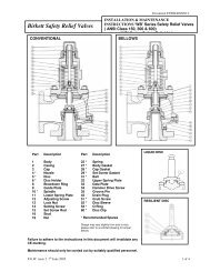


![ES139[IOM Fig 785 Marvac Emergency Relief Vent]](https://img.yumpu.com/43585698/1/190x245/es139iom-fig-785-marvac-emergency-relief-vent.jpg?quality=85)