RADIO KEY® Installation Instructions µ - Secura Key
RADIO KEY® Installation Instructions µ - Secura Key
RADIO KEY® Installation Instructions µ - Secura Key

Create successful ePaper yourself
Turn your PDF publications into a flip-book with our unique Google optimized e-Paper software.
l<br />
l<br />
¿<br />
¿<br />
¿<br />
¿<br />
¿<br />
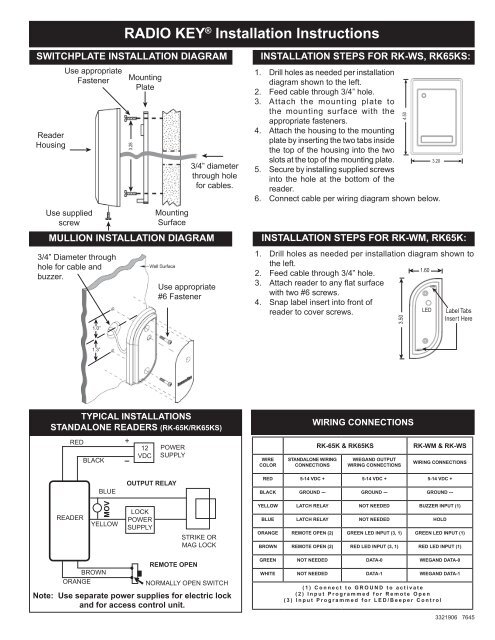
<strong>RADIO</strong> KEY ® <strong>Installation</strong> <strong>Instructions</strong><br />
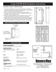
SWITCHPLATE INSTALLATION DIAGRAM<br />
Reader<br />
Housing<br />
Use appropriate<br />
Fastener<br />
¿<br />
Use supplied<br />
screw<br />
¿<br />
Mounting<br />
Plate<br />
¿<br />
¿<br />
3.28<br />
Mounting<br />
Surface<br />
MULLION INSTALLATION DIAGRAM<br />
3/4” Diameter through<br />
hole for cable and<br />
buzzer.<br />
1.0”<br />
l<br />
¿<br />
l<br />
3/4” diameter<br />
through hole<br />
for cables.<br />
Use appropriate<br />
#6 Fastener<br />
l<br />
INSTALLATION STEPS FOR RK-WS, RK65KS:<br />
1. Drill holes as needed per installation<br />
diagram shown to the left.<br />
2. Feed cable through 3/4” hole.<br />
3. Attach the mounting plate to<br />
the mounting surface with the<br />
appropriate fasteners.<br />
4. Attach the housing to the mounting<br />
plate by inserting the two tabs inside<br />
the top of the housing into the two<br />
slots at the top of the mounting plate.<br />
3.20<br />
5. Secure by installing supplied screws<br />
into the hole at the bottom of the<br />
reader.<br />
6. Connect cable per wiring diagram shown below.<br />
INSTALLATION STEPS FOR RK-WM, RK65K:<br />
1. Drill holes as needed per installation diagram shown to<br />
the left.<br />
2. Feed cable through 3/4” hole.<br />
3. Attach reader to any flat surface<br />
with two #6 screws.<br />
4. Snap label insert into front of<br />
1.60 ¿<br />
reader to cover screws.<br />
LED Label Tabs<br />
Insert Here<br />
¿<br />
3.50<br />
¿<br />
4.50<br />
¿<br />
¿<br />
¿<br />
¿<br />
1.3”<br />
l<br />
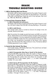
TYPICAL INSTALLATIONS<br />
STANDALONE READERS (RK-65K/RK65KS)<br />
RED<br />
BLACK<br />
+<br />
12<br />
VDC<br />
POWER<br />
SUPPLY<br />
WIRE<br />
COLOR<br />
STANDALONE WIRING<br />
CONNECTIONS<br />
WIRING CONNECTIONS<br />
RK-65K & RK65KS<br />
WIEGAND OUTPUT<br />
WIRING CONNECTIONS<br />
RK-WM & RK-WS<br />
WIRING CONNECTIONS<br />
BLUE<br />
OUTPUT RELAY<br />
RED 5-14 VDC + 5-14 VDC + 5-14 VDC +<br />
BLACK GROUND --- GROUND --- GROUND ---<br />
READER<br />
MOV<br />
YELLOW<br />
LOCK<br />
POWER<br />
SUPPLY<br />
STRIKE OR<br />
MAG LOCK<br />
YELLOW LATCH RELAY NOT NEEDED BUZZER INPUT (1)<br />
BLUE LATCH RELAY NOT NEEDED HOLD<br />
ORANGE REMOTE OPEN (2) GREEN LED INPUT (3, 1) GREEN LED INPUT (1)<br />
BROWN REMOTE OPEN (2) RED LED INPUT (3, 1) RED LED INPUT (1)<br />
BROWN<br />
ORANGE<br />
REMOTE OPEN<br />
Normally Open Switch<br />
Note: Use separate power supplies for electric lock<br />
and for access control unit.<br />
<strong>µ</strong><br />
GREEN NOT NEEDED DATA-0 WIEGAND DATA-0<br />
WHITE NOT NEEDED DATA-1 WIEGAND DATA-1<br />
( 1 ) C o n n e c t t o G R O U N D t o a c t i v a t e<br />
( 2 ) I n p u t P r o g r a m m e d f o r R e m o t e O p e n<br />
( 3 ) I n p u t P r o g r a m m e d f o r L E D / B e e p e r C o n t r o l<br />
3321906 7645
Parts Supplied:<br />
Access Control Unit<br />
MOV (RK65K & RK65KS only)<br />
Operating Guide (RK65K & RK65KS only)<br />
<strong>Installation</strong> <strong>Instructions</strong> all Models<br />
Log Sheet (RK-65K only)<br />
Mounting Plate (RK-WS, RK65KS only)<br />
2, #6 Mounting Screws<br />
1, 4x40 Screw (RK-WS, RK65KS only)<br />
1, Security Screw (RK-WS, RK65KS only)<br />
Snap-In Labels (RK65K only)<br />
Accessories (not included):<br />
RK600-PS: 9VDC plug-in power supply.<br />
It is designed to power the RK-65K and RK-65KS only,<br />
and requires 120 VAC input.<br />
RK-PD1: Proximity Programming Deck<br />
RK-BB: Back Box/Spacer (RK-WS & RK65KS)<br />
RK-HHP: Hand-Held Programmer (RK65K)<br />
SK-SR SecuRelay - Smart relay module, DPDT.<br />
SPECIFICATIONS:<br />
POWER REQUIREMENTS<br />
5-14 VDC, 90 mA<br />
OUTPUTS<br />
SPST Solid State Relay, 1A max. @60 VAC or DC<br />
Normally open or normally closed (field programmable<br />
(See Operating Guide). For RK-65K and RK-65KS only.<br />
INPUTS<br />
Default is Remote Open (requires contact closure). For RK-65K and RK-65KS only.<br />
Also programmable as Bicolor (Red or Green) LED Control or Buzzer/LED control<br />
for online systems (see Operating Guide).<br />
WIEGAND OUTPUT<br />
Any Wiegand Format up to 40 bits<br />
Maximum Distance: 500 ft. - 5 or 6 conductor 20 gauge shielded cable<br />
ENVIRONMENT<br />
Access Control Unit, <strong>Key</strong> Tags and Cards<br />
Ambient Temperature<br />
-40° to +70°C (-40° to +158°F)<br />
Humidity<br />
0 to 95% (non-condensing)<br />
INSTRUCTION TO THE USER<br />
FCC ID: NNHRK100M<br />
This equipment has been tested and found to comply with the limits for a class B digital device, pursuant to part 15 of the FCC Rules. These limits are<br />
designed to provide reasonable protection against harmful interference in a residential installation. This equipment generates, uses and can radiate radio<br />
frequency energy and if not installed and used in accordance with the instructions, may cause harmful interference to radio communications. However,<br />
there is no guarantee that interference will not occur in a particular installation. If this equipment does cause harmful interference to radio or television<br />
reception, which can be determined by turning the equipment off and on, the user is encouraged to try to correct the interference by one or more or the<br />
following measures:<br />
• Reorient or relocate the receiving antenna.<br />
• Increase the separation between the equipment and receiver.<br />
• Connect the equipment into an outlet of a circuit different from that to which the receiver is connected.<br />
• Consult the dealer or an experienced radio/TV technician for help.<br />
This equipment has been certified to comply with the limits for a class B computing device, pursuant to FCC Rules. In order to maintain compliance with FCC<br />
regulations, shielded cables must be used with this equipment. Operation with non-approved equipment or unshielded cables is likely to result in interference to<br />
radio and TV reception. The user is cautioned that changes and modifications made to the equipment without the approval of the manufacturer could void the<br />
user’s authority to operate this equipment.<br />
IP64<br />
RoHS<br />
3059349<br />
3321906 7645<br />
20301 Nordhoff Street, Chatsworth, CA 91311<br />
PHONE (818) 882-0020 • FAX (818) 882-7052<br />
TOLL-FREE (800) 891-0020<br />
Website: www.securakey.com<br />
E-mail: mail@securakey.com