Cooling Systems - HYDAC USA
Cooling Systems - HYDAC USA
Cooling Systems - HYDAC USA

Create successful ePaper yourself
Turn your PDF publications into a flip-book with our unique Google optimized e-Paper software.
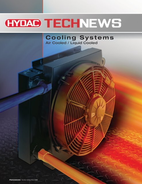
PN#02085359 / 12.12 / COL1112-1396<br />
<strong>Cooling</strong> <strong>Systems</strong><br />
Air Cooled / Liquid Cooled
About <strong>HYDAC</strong><br />
<strong>HYDAC</strong> stands for worldwide presence and accessibility to the customer. With more than 6,500 employees, 50 overseas<br />
subsidiaries and 500 plus sales and service partners worldwide, we are in close contact with our customers, providing<br />
engineering advice, production support, expert installation and superior service. <strong>HYDAC</strong> has been active in the field of<br />
hydraulic and lube filtration for more than 50 years and has become one of the leaders in innovative filtration products in<br />
hydraulics and lube oil systems. No matter what the job entails and irrespective of location, we are able to help you find<br />
the best solution—we’ve got you covered.<br />
<strong>HYDAC</strong> Products<br />
Our product range extends from air to water oil coolers. <strong>HYDAC</strong> is capable of<br />
integrating products into cooler solutions for both industrial and mobile applications.<br />
<strong>HYDAC</strong> Quality<br />
<strong>HYDAC</strong> stands for quality and customer satisfaction. We are certified to<br />
ISO 9001:2000 and can supply our products with certification if required.<br />
To ensure that our products are as innovative as possible, they are developed,<br />
manufactured, and tested by qualified personnel using advanced technology.<br />
<strong>HYDAC</strong> Customer Service<br />
Our internal staff and worldwide distribution network take care of the important<br />
matter of customer service. <strong>HYDAC</strong> values high standards, professional ethics,<br />
and mutual respect in all transactions with customers, vendors, and employees.<br />
We invest in our relationships by providing expertise, quality, dependability, and<br />
accessibility to foster growth and a sense of partnership. Our customer service<br />
representatives are committed to serving the customers’ needs.<br />
Energy and Environmental Technology<br />
<strong>HYDAC</strong> Products plays a key role in providing<br />
innovative developments in hydroelectric, heating,<br />
wind, and waste power plants. <strong>HYDAC</strong> has vast<br />
expertise in solvent and waste water processing<br />
technologies.<br />
Offshore Shipbuilding and Marine Technology<br />
Maritime technology places special demands<br />
on material functionality and reliability. <strong>HYDAC</strong><br />
filtration products meet these demands due to our<br />
high quality and test standards. <strong>HYDAC</strong> filters have<br />
been applied under the toughest conditions from<br />
drilling rigs to deep sea applications.<br />
Mobile Market<br />
The aim of our engineers has always been to reduce<br />
volume and weight, resulting in increased product<br />
performance. <strong>HYDAC</strong> provides high performance<br />
filters for the Mobile Market, which can be found on<br />
construction, forestry, and agricultural equipment.<br />
Process Technology<br />
The core products of <strong>HYDAC</strong> process technology<br />
are electronics, filters, and filtration systems for the<br />
industrial and environmental processing industries.<br />
<strong>HYDAC</strong> filtration products are found in chemical,<br />
petrochemical, and plastics industries. Also, paper<br />
and dye production, foundries, steel manufacturing,<br />
and power plants.<br />
Industrial Engineering<br />
Since we began, <strong>HYDAC</strong> has been involved in<br />
many industrial engineering applications. Our<br />
knowledge and expertise of many industries<br />
provides a comprehensive range of filters. <strong>HYDAC</strong><br />
offers custom filtration solutions for machine tools,<br />
plastic injection molding machines, test equipment,<br />
presses, and welding robots. Other industrial<br />
applications include: steel and heavy industry,<br />
power transmissions, and paper mills.<br />
PN#02085359 / 12.12 / COL1112-1396
Table of Contents<br />
<strong>HYDAC</strong> Coolers Overview<br />
Advantages .............................1<br />
Selection Requirements ...................1<br />
Selection Worksheet<br />
OK / OKC / ELD / ELH / SC Series ...........2<br />
Mobile Coolers<br />
Air Cooled<br />
ELD Series. ............................3<br />
ELH Series. ............................9<br />
Industrial Coolers<br />
Air Cooled<br />
OKC Series ...........................15<br />
OK Series ............................21<br />
SC Series. ............................29<br />
Air Cooled Accessories .................35<br />
Water Cooled<br />
PFC Series. ...........................37<br />
Selection Worksheet. ...................46<br />
Plate Heat Exchangers<br />
HEX Series ...........................47<br />
H Series. .............................51<br />
Selection Worksheet. ...................56<br />
IMPORTANT!<br />
The following series, in this<br />
catalog, have been discontinued:<br />
OK Series<br />
SC Series<br />
PFC Series<br />
Combi-Coolers<br />
Combi-Coolers .........................57<br />
Selection Worksheet .....................58<br />
Competitor Crossover<br />
Cooler Crossovers. ......................59<br />
PN#02085359 / 12.12 / COL1112-1396<br />
Coolers Catalog
Overview<br />
Advantages<br />
The advantages of an off line cooling system are a stable cooling and<br />
filtration performance irrespective of variations in flow and duty cycle<br />
of the main hydraulic circuit. This allows the cooler to be sized to fit<br />
the heat load and not the maximum return flow of the main circuit.<br />
A further advantage is that the offline cooler is completely isolated<br />
from surge pressures in the return line that can potentially damage<br />
the cooler. Also, maintenance can be performed on the filters without<br />
having to shut down the main system.<br />
Selection Requirements<br />
The following parameters need to be known to correctly size a cooler:<br />
• How much heat needs to be removed from the system<br />
• What is the desired oil temperature<br />
• What is the supplied water temperature and ambient air temperature<br />
• What is the flow required<br />
• What is the desired oil to water flow ratio<br />
• What is the viscosity of the oil<br />
1. Required Flow<br />
As a rule of thumb, the pump should be sized so that it circulates approximately 25 to 30% of the reservoir’s capacity.<br />
Note: Before sizing the heat exchanger, the flow rate needs to be known.<br />
2. Heat Removed<br />
The main function of the cooler is to transfer heat from the oil into the water. Heat load is generally described in units of HP, kW, or BTU’s/Hr<br />
being removed. When designing a new system, a good rule of thumb is a cooler should be sized to remove approximately 25 to 30 % of the<br />
input HP or kW.<br />
In an existing system with a heat problem and the heat load is not known, then a heat load test needs to be performed. The test is performed<br />
by measuring the temperature rise of the oil over a certain period of time. Take this temperature rise and time in minutes and use it in the<br />
following formula to determine the kW heat load.<br />
Heat Load Pv =<br />
Temperature rise (˚C) x Specific Heat (1.88 KJ/Kgk) x Density of oil (0.951 Kg/l) x Volume (l)<br />
Operating time (Minutes) X 60<br />
HP = kW x 1.341<br />
See example of heat load calculation below.<br />
3. Oil/Water Temperatures<br />
The inlet oil temperature is the desired temperature of the oil in the reservoir. The inlet water temperature is the water temperature entering the<br />
cooler unit.<br />
4. Flow Ratio<br />
Maximum capacity of a cooler is achieved when the oil to water ratio is 1:1. This is desirable where the water supply is plentiful, as this will be<br />
the smallest, least expensive cooler. As the ratio increases, the cooling capacity decreases and a larger cooler will be required. This option<br />
costs more initially, but will save on water usage.<br />
Heat Load Calculation Example<br />
Pv (Heat Load) = kW<br />
∆T (Temperature Rise) = 34.4˚C (93.9˚F)<br />
SH (Specific Heat of oil) = 1.88 KJ/Kgk<br />
SG (Specific Gravity of oil) = 0.915 Kg/l<br />
V (Tank Volume) = 380 l (100 Gal)<br />
t (Time in Minutes) = 45 min.<br />
Pv = ∆T x SHoil x SGoil x V = kW<br />
t x 60<br />
Pv = 34.4 x 1.88 x 0.915 x 380 = 8.32 kW<br />
45 x 60<br />
HP = 8.32 x 1.341 = 11.16<br />
Heat to be removed = 11.16 HP<br />
For more information, please visit us at www.hydacusa.com<br />
2 INNOVATIVE FLUID POWER<br />
PN#02085359 / 12.12 / COL1112-1396
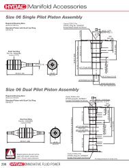
Overview<br />
Applications<br />
Mobile Applications<br />
• Agricultural<br />
• Construction<br />
• Railways<br />
• Environmental Control<br />
• Cranes<br />
• Forestry Equipment<br />
• Commercial Vehicles<br />
• Firetruck<br />
• Cement Truck<br />
• Utility Truck<br />
• Forklift<br />
Power Generations<br />
• Power Plant<br />
• <strong>Cooling</strong> Tower<br />
• Gas Turbine<br />
*<br />
Wind Energy<br />
1. Inverter cooling<br />
2. Heat exchangers & coolers<br />
3. Generator cooling<br />
4. Gear cooling, lubrication<br />
and inline filtration<br />
*<br />
Industrial Applications<br />
• Industrial<br />
• Elevators<br />
• Shipbuilding<br />
• Heavy Industry<br />
• Gearboxes<br />
• Test Stands<br />
2<br />
3<br />
4<br />
1<br />
1<br />
1<br />
For more product offerings and application information on the<br />
adjacent coolers, please see Combi Cooler section of this catalog.<br />
For more information, please visit us at www.hydacusa.com<br />
PN#02085359 / 12.12 / COL1112-1396<br />
INNOVATIVE FLUID POWER 3
ELD Series<br />
Air Cooled Oil Coolers for Mobile Applications<br />
Hydraulic Symbol<br />
Sizes 1 - 4.5<br />
Sizes 5 - 6<br />
Description<br />
These coolers use a combination of high performance cooling<br />
elements combined long life DC electrical powered fans to give long<br />
trouble free operation in mobile hydraulic applications. The compact<br />
design allows the coolers to fit most equipment and provide the<br />
highest cooling performance in heat dissipation while minimizing<br />
space required.<br />
Agricultural<br />
Automotive<br />
Construction<br />
Commercial<br />
Municipal<br />
Features<br />
• Most coolers are designed with the inlet/outlet ports facing<br />
toward the back to help reduce fittings<br />
• Available with internal pressure bypass<br />
Railways<br />
• All units feature a built in thermostat port<br />
• 12 and 24 volt DC fans<br />
• Up to 50 HP cooling capacity<br />
• Rated flows up to 45 gpm<br />
• Motor lifetimes up to 8,000 hours<br />
For more information, please visit us at www.hydacusa.com<br />
4 INNOVATIVE FLUID POWER<br />
PN#02085359 / 12.12 / COL1112-1396
Coolers<br />
Model Code<br />
Model<br />
ELD = Air Cooled Oil Cooler with DC Motor Drive<br />
Size<br />
1.5H<br />
2H<br />
3H<br />
4H<br />
4.5H<br />
5H<br />
6H<br />
(see heat dissipation table on page 5)<br />
Modification Number (latest version always supplied)<br />
Motor Drive Voltage<br />
12 = 12 volt DC<br />
24 = 24 volt DC<br />
Air Flow Direction<br />
S = Suction (standard)<br />
B = Blowing (consult factory)<br />
Accessories<br />
TS 140 = 140°F set point (Additional set points available - consult factory)<br />
F = Optional Foot Mount<br />
IBP = Integrated bypass valve<br />
IBT = Thermostatic bypass valve<br />
Opening Pressure Drop (IBP Only)<br />
2 = 2 bar (29 psi)<br />
3 = 3 bar (45 psi)<br />
Opening Temperature (IBP Only)<br />
45 = 113°F (45°C)<br />
50 = 130°F (55°C)<br />
60 = 140°F (60°C)<br />
Closing Temperature (IBP Only)<br />
45 = 131°F (55°C)<br />
50 = 150°F (65°C)<br />
60 = 158°F (70°C)<br />
ELD 1.5H 3.5 12 S F X<br />
PN#02085359 / 12.12 / COL1112-1396<br />
INNOVATIVE FLUID POWER 5
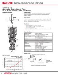
Coolers<br />
ELD Series<br />
Heat Dissipation<br />
<strong>Cooling</strong> capacity depending on oil flow and the temperature differential ∆T between the oil inlet. For<br />
calculations with low ∆T valves (i.e. below 20˚F), please contact our technical support.<br />
Tolerance: +/- 5%<br />
50<br />
45<br />
ELD 6<br />
40<br />
35<br />
ELD 5<br />
30<br />
25<br />
20<br />
15<br />
10<br />
5<br />
0<br />
ELD 2<br />
ELD 1.5<br />
ELD 1<br />
ELD 4.5<br />
ELD 3<br />
ELD 4<br />
0 5 10 15 20 25 30 35 40 45 50 55 60 65<br />
Oil flow [GPM]<br />
60.0<br />
ELD 1: +/- 5%<br />
55.0<br />
Pressure Drop @ 30 mm/s (PSI)<br />
50.0<br />
45.0<br />
40.0<br />
35.0<br />
30.0<br />
25.0<br />
20.0<br />
15.0<br />
ELD 1<br />
ELD 1.5<br />
ELD 5<br />
ELD 6 ELD 3<br />
ELD 4<br />
ELD 2<br />
10.0<br />
5.0<br />
0.0<br />
0 20 40 60 80<br />
Oil flow (GPM)<br />
*Values measured at T = 72°F, may vary at lower dT values<br />
ELD 4.5<br />
6 INNOVATIVE FLUID POWER<br />
PN#02085359 / 12.12 / COL1112-1396
Coolers<br />
General<br />
Housing<br />
Welded steel<br />
Construction<br />
Heat Exchanger<br />
Aluminum<br />
Fan<br />
Plastic<br />
Mounting Orientation<br />
All positions<br />
Maximum Pressure<br />
230 psi (16 bar)<br />
Fluids Mineral oil to DIN 51524 Part 1 and 2<br />
Ambient Temperature<br />
50° - 104° F (10° - 40°C)<br />
Maximum Oil Temperature<br />
266° F (130°C)<br />
Air Flow Direction<br />
Pulled across heat exchanger<br />
Specifications<br />
Size<br />
ELD 1<br />
12 volt / 24 volt<br />
ELD 1.5<br />
12 volt / 24 volt<br />
ELD 2<br />
12 volt / 24 volt<br />
ELD 3<br />
12 volt / 24 volt<br />
ELD 4<br />
12 volt / 24 volt<br />
ELD 4.5<br />
12 volt / 24 volt<br />
ELD 5<br />
12 volt / 24 volt<br />
ELD 6<br />
12 volt / 24 volt<br />
Motor Capacity<br />
(kW)<br />
Amp Draw<br />
Protection<br />
Class IP<br />
Fan Diameter<br />
(mm)<br />
Noise Level<br />
dBa* (1 meter)<br />
Weight<br />
(lbs.)<br />
0.11 / 0.11 8 / 3.9 68 190 73 8.8<br />
0.11 / 0.11 8 / 3.9 68 190 73 8.8<br />
0.16 / 0.16 9.4 / 5.2 68 255 74 20.688<br />
0.26 / 0.26 17.6 / 9.6 68 305 79 24.2<br />
0.35 / 0.35 24.2 / 10 68 385 76 34.98<br />
0.35 / 0.35 24.2 / 10 68 385 76 48.4<br />
0.53 / 0.53 35.2 / 19.2 68 305 80 66.66<br />
0.69 / 0.69 48.4 / 20 68 385 77 80.52<br />
*The noise levels are only a guide as acoustic properties vary and depend on the characteristics of the room, connections, viscosity, and<br />
resonance.<br />
Dimensions are for general information only, all critical dimensions should be verified by requesting a certified print.<br />
Dimensions are in inches/(mm).<br />
PN#02085359 / 12.12 / COL1112-1396<br />
INNOVATIVE FLUID POWER 7
Coolers<br />
ELD Series<br />
Dimensions<br />
Sizes 1 - 4<br />
W2<br />
B<br />
W1<br />
E5<br />
E5<br />
Thermostat Port<br />
STANDARD<br />
A1<br />
E4<br />
E1<br />
AIR FLOW<br />
OPTIONAL<br />
E2<br />
øF-Mounting Hole<br />
(6 Places)<br />
E3<br />
Z1 (2x)<br />
Oil Port (2 Places)<br />
C1<br />
Size A1 B C1 E1 E2 E3 E4 E5 F W1 W2 Z1<br />
Thermostat<br />
Port<br />
ELD 1 9.65 4.72 11.81 4.92 2.36 9.84 8.86 3.54 0.35 7.87 3.94 1 1/16”-12 UN 1/2” NPT<br />
ELD 2 12.32 8.27 15.12 7.83 2.24 12.76 11.34 3.15 0.55 x 0.4 9.84 5.91 1 5/16”-12 UN 1/2” NPT<br />
ELD 3 14.02 8.27 16.54 9.06 2.48 14.57 12.95 3.94 0.55 x 0.4 11.81 7.09 1 5/16”-12 UN 1/2” NPT<br />
ELD 4 17.72 7.83 19.69 11.38 3.17 17.72 16.57 5.91 0.63 x 0.4 15.75 7.87 1 5/16”-12 UN 1/2” NPT<br />
Size 1.5<br />
Z1<br />
Oil Port<br />
(2 Places)<br />
E6<br />
E3<br />
Thermostat<br />
Port<br />
W2<br />
E1<br />
B<br />
W1<br />
A1<br />
E4<br />
(4x) F<br />
E2<br />
C1<br />
E7<br />
E5<br />
Size A1 B C1 E1 E2 E3 E4 E5 E6 E7 F W1 W2 Z1<br />
Thermostat<br />
Port<br />
ELD 1.5 8.07 5.30 11.81 1.22 1.54 10.04 4.76 1.57 0.89 0.49 5/16”-18 UNC 0.31 0.16 1 1/16”-12 UN 1/2” NPT<br />
8 INNOVATIVE FLUID POWER<br />
PN#02085359 / 12.12 / COL1112-1396
Coolers<br />
ELD Series<br />
Dimensions<br />
Sizes 4.5<br />
C1<br />
Thermostat Port<br />
E3<br />
W2<br />
B<br />
W1<br />
øF - Mounting<br />
Hole (4 places)<br />
E2<br />
STANDARD<br />
AIR FLOW<br />
E1<br />
AIR FLOW<br />
DIRECTION<br />
E4<br />
A1<br />
PER REQUEST<br />
STANDARD<br />
W2<br />
OPTIONAL<br />
E5<br />
Size A1 B C1 E1 E2 E3 E4 E5 F W1 W2 Z1<br />
Thermostat<br />
Port<br />
ELD 4.5 17.87 8.58 23.70 13.78 2.05 19.29 7.87 11.42 0.472 15.75 7.87 1 5/8”-12 UN 1/2” NPT<br />
Sizes 5 - 6<br />
E5<br />
E5<br />
E5<br />
Thermostat Port<br />
E2<br />
A1<br />
E4<br />
E1<br />
B<br />
W1<br />
Z1 Oil Port<br />
(2 places)<br />
E5<br />
E3<br />
C1<br />
Ø F - Mounting Hole (8 places)<br />
Z1<br />
Oil Port (2 places)<br />
Size A1 B C1 E1 E2 E3 E4 E5 F W1 W2 Z1<br />
Thermostat<br />
Port<br />
ELD 5 18.70 9.25 31.89 12.64 3.03 29.53 17.72 6.69 0.63 x 0.35 15.75 7.87 1 5/8”-12 UN 1/2” NPT<br />
ELD 6 20.94 8.86 37.40 14.69 3.11 35.04 19.80 7.87 0.71 x 0.35 19.69 9.84 1 5/8”-12 UN 1/2” NPT<br />
PN#02085359 / 12.12 / COL1112-1396<br />
INNOVATIVE FLUID POWER 9
ELH Series<br />
Air Cooled Oil Coolers for Mobile Applications<br />
Hydraulic Symbol<br />
Description<br />
These coolers use a combination of high performance cooling<br />
elements combined with high capacity hydraulic drive fan to give<br />
long trouble free operation in mobile hydraulic applications. The<br />
compact design allows the coolers to fit most equipment and<br />
provide the highest cooling performance in heat dissipation while<br />
minimizing space required.<br />
Agricultural<br />
Automotive<br />
Construction<br />
Railways<br />
Features<br />
• ELD 2 - 5 coolers are designed with the inlet/outlet ports facing<br />
towards the back to help reduce fittings<br />
• Available with internal pressure and temperature bypass<br />
• All units feature a built in thermostat port<br />
Industrial<br />
Commercial<br />
Municipal<br />
• Up to 180 HP cooling capacity<br />
• Rated flows up to 90 gpm<br />
• Hydraulic motor drive offers more cooling in a smaller package<br />
• Optional thermal speed control and pressure relief<br />
(Consult Factory)<br />
For more information, please visit us at www.hydacusa.com<br />
10 INNOVATIVE FLUID POWER<br />
PN#02085359 / 12.12 / COL1112-1396
Coolers<br />
Model Code<br />
Model<br />
ELH = Air Cooled Oil Cooler with Hydraulic Motor Drive<br />
Size (See the heat transfer table found on page 11 to determine the proper size.)<br />
2<br />
3<br />
4<br />
5<br />
6<br />
7<br />
8<br />
9<br />
10<br />
11<br />
Modification Number (latest version always supplied)<br />
Hydraulic Motor Drive Displacement<br />
H6.3 = 6.3 ccm/rev<br />
H14 = 14 ccm/rev<br />
H22 = 22 ccm/rev<br />
Air Flow Direction<br />
S = Suction (standard)<br />
B = Blowing (consult factory)<br />
Accessories<br />
F = Optional Foot Mount (sizes 2 - 4 only)<br />
IBT = thermostatic bypass valve<br />
IBP = integrated bypass valve<br />
Opening Temperature (IBT only)<br />
Opening Temp. Closing Temp.<br />
45 = 113°F (45°C) 131°F (55°C)<br />
50 = 130°F (55°C) 150°F (65°C)<br />
60 = 140°F (60°C) 158°F (70°C)<br />
Opening Pressure Drop (IBT & IBP only)<br />
2 = 2 bar (29 psi)<br />
3 = 3 bar (45 psi)<br />
ELH 2 1.5 H6.3 S F XX X<br />
PN#02085359 / 12.12 / COL1112-1396<br />
INNOVATIVE FLUID POWER 11
Coolers<br />
ELH Series<br />
Heat Dissipation<br />
<strong>Cooling</strong> capacity depending on oil flow and the temperature differential ∆T between the oil inlet and air inlet. For calculations<br />
with low ∆T valves (i.e. below 20˚F), please contact our technical support.<br />
Sizes 2 - 5<br />
50<br />
45<br />
40<br />
35<br />
ELH-5 3000<br />
ELH-4 3000<br />
30<br />
25<br />
20<br />
ELH-5 1500<br />
ELH-4 1500<br />
ELH-3 3000<br />
15<br />
10<br />
5<br />
ELH-2 3000<br />
ELH-2 1500<br />
ELH-3 1500<br />
Sizes 6 - 11<br />
0<br />
0<br />
200<br />
180<br />
5 10 15 20 25 30 35 40 45 50 55 60 65 70 75 80<br />
Oil Flow (GPM)<br />
ELH-11 1600<br />
160<br />
140<br />
120<br />
100<br />
80<br />
60<br />
40<br />
20<br />
ELH-7 2000<br />
ELH-6 1000<br />
ELH-10 1800<br />
ELH-9 2200<br />
ELH-10 1000<br />
ELH-8 2800<br />
ELH-9 1000<br />
ELH-7 1500<br />
ELH-6 3000 ELH-7 1000<br />
ELH-8 1000<br />
ELH-11 1000<br />
Pressure Drops<br />
Pressure differential ∆p depending on flow rate Q and<br />
the viscosity of the oil.<br />
45<br />
0<br />
0<br />
10 20 30 40 50 60 70 80 90 100<br />
Oil Flow (GPM)<br />
40<br />
ELH 3<br />
ELH 4<br />
35<br />
Pressure Drop @ 1.18” 2 /s (psi)<br />
30<br />
25<br />
20<br />
15<br />
ELH 2<br />
ELH 6<br />
ELH 5 ELH 7<br />
ELH 8<br />
ELH 9<br />
ELH 10<br />
ELH 11<br />
10<br />
5<br />
0<br />
0<br />
10<br />
20<br />
30<br />
40<br />
50<br />
60<br />
70<br />
80<br />
90<br />
Oil Flow (gpm)<br />
12 INNOVATIVE FLUID POWER<br />
PN#02085359 / 12.12 / COL1112-1396
Coolers<br />
General<br />
Construction Housing Welded Steel<br />
Heat Exchanger<br />
Aluminum<br />
Fan<br />
Plastic<br />
Motor<br />
Aluminum housing, Steel gears and shaft<br />
Maximum Oil Temperature<br />
266 F<br />
Maximum Operating Pressure<br />
230 psi<br />
Mounting Orientation<br />
All positions<br />
Fan Rotation<br />
See arrow on housing<br />
Filtration ISO/DIS 4406 Code 19/16- Filtration grade B25>75<br />
Maximum Outlet Side Pressure<br />
1740 psi<br />
Maximum Drain Pressure<br />
29 psi<br />
Fluid Viscosity Range (Motor)<br />
10 - 600 cst. (recommended 30 - 45 cst.)<br />
Fluid Temperature Range (Motor)<br />
Up to 194˚ F<br />
Specifications<br />
Model<br />
Motor<br />
Displacement<br />
(cm3/rev)<br />
Operating<br />
Speed Range<br />
(rpm)<br />
∆p of motor<br />
@ max RPM<br />
@ 34 cts (psi)<br />
Motor oil flow<br />
@ 1500 rpm<br />
(gpm)<br />
Motor Max.<br />
Pressure (psi)<br />
Continuous Motor<br />
Operating Pressure<br />
(psi)<br />
Noise level<br />
@ 1000 RPM<br />
(dBa) (1 Meter)*<br />
ELH 2 6.3 / 14 / 22 1000 / 3000 290 2.8 / 6 / 9.7 4350 / 4350 / 2900 3625 / 3625 / 2175 69 24.3<br />
ELH 3 6.3 / 14 / 22 1000 / 3000 290 2.8 / 6 / 9.7 4350 / 4350 / 2900 3625 / 3625 / 2175 69 28.7<br />
ELH 4 6.3 / 14 / 22 1000 / 3000 725 / 435 / 290 2.8 / 6 / 9.7 4350 / 4350 / 2900 3625 / 3625 / 2175 70 40.0<br />
ELH 5 6.3 / 14 / 22 1000 / 3000 1015 / 435 / 290 2.8 / 6 / 9.7 4350 / 4350 / 2900 3625 / 3625 / 2175 70 53.0<br />
ELH 6 6.3 / 14 / 22 1000 / 3000 2175 / 1015 / 725 2.8 / 6 / 9.7 4350 / 4350 / 2900 3625 / 3625 / 2175 70 94.6<br />
ELH 7 14 / 22 1000 / 3000 6 / 9.7 4350 / 2900 3625 / 2175 77 TBA<br />
ELH 8 6.3 / 14 / 22 1000 / 2800 2900 / 1160 / 870 2.8 / 6 / 9.7 4350 / 4350 / 2900 3625 / 3625 / 2175 76 147.7<br />
ELH 9 14 / 22 1000 / 2200 1885 / 1305 6 / 9.7 4350 / 2900 3625 / 2175 78 187.4<br />
ELH 10 14 / 22 1000 / 1800 3335 / 1885 6 / 9.7 4350 / 2900 3625 / 2175 82 242.5<br />
ELH 11 14 / 22 1000 / 1600 3625 / 2175 6 / 9.7 4350 / 2900 3625 / 2175 83 341.7<br />
*The noise levels are only a guide as acoustic properties vary and depend on the characteristics of the room, connections, viscosity, and resonance.<br />
Weight<br />
(lbs.)<br />
PN#02085359 / 12.12 / COL1112-1396<br />
INNOVATIVE FLUID POWER 13
Coolers<br />
ELH Series<br />
Dimensions<br />
Sizes 2 - 4<br />
6x øF<br />
E5<br />
E5<br />
Thermostat<br />
Port<br />
W2<br />
W1<br />
Ports<br />
7/8-14UNF<br />
Size<br />
A1<br />
B<br />
6.3 cc<br />
B<br />
14 cc<br />
B<br />
22 cc<br />
C1 E1 E2 E3 E4 E5 F W1 W2 Z1<br />
Thermostat<br />
Port<br />
ELH 2 12.32 10.63 11.14 11.70 15.12 7.83 2.20 12.76 11.34 3.15 0.55 x 0.4 7.87 5.91 1-5/16”-12 UN 1/2” NPT<br />
ELH 3 14.02 10.99 11.49 12.05 16.54 9.06 2.48 14.57 12.95 3.94 0.55 x 0.4 9.84 7.09 1-5/16”-12 UN 1/2” NPT<br />
ELH 4 17.72 11.56 12.06 12.62 19.69 11.38 3.17 17.72 16.57 5.91 0.49 x 0.39 13.78 7.87 1-5/16”-12 UN 1/2” NPT<br />
Fixing Point 4x ø12<br />
W2<br />
W1<br />
PLUG<br />
Z1 (2x)<br />
A1<br />
E1<br />
E4<br />
E2<br />
E1<br />
A1<br />
E4<br />
Drain Port<br />
7/16-20UNF<br />
E3<br />
C1<br />
Z1 (2x)<br />
B<br />
Size 5<br />
E2<br />
E3<br />
E5<br />
C1<br />
B<br />
Size<br />
A1<br />
B<br />
6.3 cc<br />
B<br />
14 cc<br />
B<br />
22 cc<br />
ÿ 15<br />
C1 E1 E2 E3 E4 E5 F W1 W2 Z1<br />
ÿ 35<br />
Thermostat<br />
Port<br />
ELH 5 18.11 12.25 12.73 13.29 23.70 13.78 2.17 19.29 7.87 22.83 0.47 15.75 9.84 1-5/8”-12 UN 1/2” NPT<br />
14 INNOVATIVE FLUID POWER<br />
PN#02085359 / 12.12 / COL1112-1396
Coolers<br />
ELH Series<br />
Dimensions<br />
Sizes 6 - 8<br />
Size<br />
A1<br />
B<br />
6.3 cc<br />
B<br />
14 cc<br />
B<br />
22 cc<br />
C1 D1 D2 D3 E1 E2 E3 F W1 W2 Z1<br />
Thermostat<br />
Port<br />
ELH 6 25.12 14.87 15.37 15.93 23.54 10.04 18.98 11.61 19.69 3.07 0.79 0.35 39.37 23.62 1-5/8”-12 UN 1/2” NPT<br />
ELH 7 28.58 - 17.50 18.06 27.80 16.14 22.05 17.72 23.62 2.87 0.79 0.35 42.00 25.00 1-5/8”-12 (F) 1/2” NPT<br />
ELH 8 30.08 15.06 15.57 16.13 27.64 10.04 18.98 11.61 24.74 3.06 0.79 0.35 43.31 27.56 1-5/8”-12 UN 1/2” NPT<br />
Sizes 9 - 11<br />
Size<br />
A1<br />
B<br />
6.3 cc<br />
B<br />
14 cc<br />
B<br />
22 cc<br />
C1 D1 D2 D3 E1 E2 E3 F W1 W2 Z1<br />
Thermostat<br />
Port<br />
ELH 9 35.83 - 19.88 20.44 32.56 16.14 27.56 17.72 29.92 3.35 3.62 0.35 47.24 35.43 1-7/8”-12 UN 1/2” NPT<br />
ELH 10 41.73 - 20.72 21.28 38.28 18.11 27.56 19.69 35.83 3.54 3.66 0.35 55.12 35.43 1-7/8”-12 UN 1/2” NPT<br />
ELH 11 46.40 - 21.49 22.05 42.91 18.11 27.56 19.69 41.73 2.95 3.66 0.35 62.99 39.37 1-7/8”-12 UN 1/2” NPT<br />
PN#02085359 / 12.12 / COL1112-1396<br />
INNOVATIVE FLUID POWER 15
OKC Series<br />
Air Cooled Oil Coolers<br />
Hydraulic Symbol<br />
Sizes 1 - 5<br />
Sizes 6 - 7<br />
Description<br />
These coolers use a combination of high performance cooling<br />
elements and high capacity, compact AC Electric powered fans to<br />
give long trouble free operation in hydraulic applications.<br />
The compact design allows the coolers to fit most equipment and<br />
provide the highest cooling performance in heat dissipation while<br />
minimizing space required.<br />
Features<br />
• <strong>Cooling</strong> Range: up to 23 HP<br />
• AC Motors in 230/460 Volt 50/60 Hz<br />
• Hydraulic Pressure: 230 psi Dynamic<br />
Gearboxes Industrial Elevators Power<br />
Generation<br />
Pulp & Paper Railways Shipbuilding Steel / Heavy<br />
Industry<br />
For more information, please visit us at www.hydacusa.com<br />
16 INNOVATIVE FLUID POWER<br />
PN#02085359 / 12.12 / COL1112-1396
Coolers<br />
Model Code<br />
Model<br />
OKC = Air Cooled Oil Cooler<br />
Size<br />
1H<br />
2H<br />
3H<br />
4S<br />
5S<br />
6H<br />
7S<br />
H = High Speed Fan<br />
S = Standard Speed Fan<br />
Modification Number (latest version always supplied)<br />
Electric Motor Fan Voltage<br />
110 = 110 Volts 50/60 Hz 1PH (consult factory)<br />
230 = 230 Volts 50/60 Hz 1PH<br />
460 = 460 Volts 50/60 Hz 3PH<br />
Air Flow Direction<br />
S = Suction<br />
Accessories<br />
TS140 = Thermostat (fixed) 140°F Set Point<br />
Other Temperature Set Points Available (consult factory)<br />
IBP = Integrated bypass valve<br />
IBT = Thermostatic bypass valve<br />
Opening Temperature (IBT Only)<br />
45 = 113°F (45°C)<br />
50 = 130°F (55°C)<br />
60 = 140°F (60°C)<br />
Closing Temperature (IBT Only)<br />
45 = 131°F (55°C)<br />
50 = 150°F (65°C)<br />
60 = 158°F (70°C)<br />
Opening Pressure Drop (IBP + IBT Only)<br />
2 = 2 bar (29 psi)<br />
3 = 3 bar (45 psi)<br />
OKC 1H 1.5 230 / S / TS140<br />
PN#02085359 / 12.12 / COL1112-1396<br />
INNOVATIVE FLUID POWER 17
Coolers<br />
OKC Series<br />
Heat Dissipation<br />
<strong>Cooling</strong> capacity depending on oil flow and the temperature differential ∆T between the oil inlet and air inlet.<br />
For calculations with low ∆T values (i.e. below 20°F), please contact our technical support.<br />
25<br />
Tolerance ±5%<br />
OKC 7S<br />
20<br />
OKC 6H<br />
15<br />
OKC 5S<br />
10<br />
OKC 4S<br />
OKC 3H<br />
5<br />
OKC 2H<br />
OKC 1H<br />
0<br />
0 5 10 15 20 25 30 35 40 45<br />
Oil FLow (GPM)<br />
50<br />
Tolerance ±5%<br />
45<br />
OKC 7<br />
Pressure Drop @ 30 mm/s (PSI)<br />
40<br />
35<br />
30<br />
25<br />
20<br />
15<br />
10<br />
OKC 1<br />
OKC 2<br />
OKC 3<br />
OKC 6<br />
OKC 4<br />
OKC 5<br />
5<br />
0<br />
0 10 20 30 40 50 60 70 80 90<br />
Oil Flow (GPM)<br />
Viscosity (mm2/s) 10 15 22 32 46 54 68 100 150<br />
K Factor 0.5 0.65 0.77 1 1.3 1.52 1.9 2.8 5.3<br />
18 INNOVATIVE FLUID POWER<br />
PN#02085359 / 12.12 / COL1112-1396
Coolers<br />
General<br />
• Electrical connection box is included<br />
• Capacitor is supplied with the cooler and mounted in the connection box<br />
• All motor with IP55 have protection class F<br />
• All mounting positions possible<br />
• For direction of rotation see arrow on cooler housing<br />
• <strong>Cooling</strong> Fluid: Mineral oil to DIN 51524<br />
Specifications<br />
Size Voltage (V) Amp Draw<br />
Speed<br />
@ 60 Hz<br />
(rpm)<br />
Noise Level<br />
dBa*<br />
(1 meter)<br />
Max.<br />
Operating<br />
Pres. (psi)<br />
Max. Oil<br />
Temperature<br />
(°F)<br />
Max.<br />
Viscosity<br />
(mm2/s)<br />
OKC 1H 230 / 460 0.52 / 0.25 3105 / 2990 71 230 266 2000 20<br />
OKC 2H 230 / 460 0.52 / 0.30 2990 / 2875 71 230 266 2000 27<br />
OKC 3H 230 / 460 0.74 / 0.56 2990 / 2875 75 230 266 2000 32<br />
OKC 4S 230 / 460 0.91 / 0.50 1610 / 1887 69 230 266 2000 47<br />
OKC 5S 230 / 460 0.91 / 0.50 1610 / 1887 72 230 266 2000 62<br />
OKC 6H 230 / 460 0.74 / 0.41 2990 / 2875 75 230 266 2000 86<br />
OKC 7S 230 / 460 0.91 / 0.50 1610 / 1887 71 230 266 2000 99<br />
Weight<br />
(lbs.)<br />
PN#02085359 / 12.12 / COL1112-1396<br />
INNOVATIVE FLUID POWER 19
Coolers<br />
OKC Series<br />
Dimensions<br />
Sizes 1<br />
Size A1 B C1 D1 D2 D3 E1 E2 E3 W1 W2 Z1<br />
OKC 1 11.81 8.07 13.39 4.33 10.63 5.35 7.94 2.48 11.81 7.87 2.76 1 1/16” -12 UNF 8.33 1/2” NPT (F)<br />
F<br />
(6xø)<br />
Plug<br />
Sizes 2 - 5<br />
Size A1 B C1 D1 D2 D3 E1 E2 E3 E4 E5 W1 W2 Z1<br />
OKC 2 12.91 11.42 15.12 10.04 6.30 11.61 7.87 2.80 12.75 11.34 3.15 9.84 5.91 1 5/16” -12 UNF 0.35 1/2” NPT (F)<br />
OKC 3 14.61 11.30 16.54 10.04 9.45 11.61 9.06 3.07 14.57 12.95 3.94 11.81 7.09 1 5/16” -12 UNF 0.35 1/2” NPT (F)<br />
OKC 4 18.31 11.50 19.69 10.04 10.04 11.61 11.38 3.76 17.72 16.57 5.91 15.75 7.87 2 5/16” -12 UNF 0.35 1/2” NPT (F)<br />
OKC 5 18.70 12.05 23.70 10.04 10.04 11.61 13.76 2.75 19.29 7.87 22.83 15.75 9.84 1 5/8” -12 UNF 0.35 1/2” NPT (F)<br />
F<br />
(4xø)<br />
Plug<br />
20 INNOVATIVE FLUID POWER<br />
PN#02085359 / 12.12 / COL1112-1396
Coolers<br />
OKC Series<br />
Dimensions<br />
Sizes 6 - 7<br />
Size A1 B C1 D1 D2 D3 E1 E2 E3 E4 E5 W1 W2 Z1<br />
OKC 6 19.49 11.38 31.89 10.04 18.98 11.61 12.68 3.70 29.53 17.72 6.69 15.75 7.87 1 5/8” -12 UNF 0.35 1/2” NPT (F)<br />
OKC 7 21.54 11.38 37.40 10.04 18.98 11.61 14.69 3.72 35.04 19.80 7.87 19.80 9.84 1 5/8” -12 UNF 0.35 1/2” NPT (F)<br />
F<br />
(4xø)<br />
Plug<br />
PN#02085359 / 12.12 / COL1112-1396<br />
INNOVATIVE FLUID POWER 21
HEX Series<br />
Plate Heat Exchangers<br />
Hydraulic Symbol<br />
AIB cooler element bypass option<br />
for high viscosity applications.<br />
Description<br />
Heat exchangers are used to exchange heat between two fluids.<br />
Plate heat exchangers are high performance components and<br />
provide a high level of efficiency combined with compact dimensions<br />
and low weight. Their efficiency reduces the amount of cooling water<br />
required for heat transfer which results in low operating costs.<br />
Features<br />
Plates and connections are manufactured from stainless steel to AISI<br />
316, 1.4401, vacuum–brazed with copper. The special moulding of<br />
the plates produces the turbulent flow necessary for effective heat<br />
transfer and provides the plate heat exchanger with a high level of<br />
mechanical strength.<br />
Corrosion:<br />
The following limits refer to a pH value of 7<br />
• free chlorine, CL2 < 0.5 ppm<br />
• chloride ions CL<br />
< 700 ppm at 20 °C<br />
< 200 ppm at 50 °C<br />
Other Limits:<br />
• ph 7 – 10<br />
• sulphate SO4 2– 1<br />
• ammonia, NH3
Plate Heat Exchangers<br />
Model Code<br />
Series<br />
HEX 610<br />
HEX 615<br />
HEX 422<br />
Number of Plates<br />
10 20 30 40 50 60 70 80 100 120<br />
610 x x x x x x x x x<br />
615 x x x x x x x<br />
422 x x x x x x x<br />
Connections<br />
CB 27 = 1” NPT Female X 4<br />
C 71 = 1” BSPP Female X 4<br />
CB 52 = 1” NPT Female X 4<br />
C 71 = 1” BSPP Female X 4<br />
CB 76 = 1 1/2” NPT Female X 4<br />
C 72 = 1 1/2” BSPP Female X 4<br />
(size 610 only)<br />
(size 615 only)<br />
(size 422 only)<br />
Pipes must be connected so that the connections are stress free.<br />
Linear expansion and vibrations from the pipes to the heat exchanger must be avoided.<br />
HEX 610 – 10 C 27<br />
Pressure drop across heat exchanger<br />
This table is based on an ISO VG45 oil at 130˚F and shows the pump flows with the 1,800 RPM motors. If other grades of oil are to be used,<br />
consult the sizing software. When using the 72 psi clogging indicator the pressure drop should not exceed 15 psi max across the heat<br />
exchanger. When using the 29 psi clogging indicator the pressure drop should not exceed 30 psi max across the heat exchanger.<br />
Heat<br />
Exchanger<br />
Size<br />
Pump 3.5<br />
1.6 gpm<br />
(6.3 l/min)<br />
Pump 7<br />
3.3 gpm<br />
(12.6 l/min)<br />
Pump 10<br />
4.75 gpm<br />
(18 l/min)<br />
Pump 15<br />
7 gpm<br />
(18 l/min)<br />
Pump 20<br />
9.5 gpm<br />
(18 l/min)<br />
Pump 30<br />
14.5 gpm<br />
(55 l/min)<br />
Pump 40<br />
18.5 gpm<br />
(70 l/min)<br />
Pump 50<br />
23.5 gpm<br />
(90 l/min)<br />
Pump 70<br />
34 gpm<br />
(130 l/min)<br />
610-10 3 5 8 - - - - - -<br />
610-20 1 2 3 5 7 13.66 - - - -<br />
610-40 - - - 2 3 7.35 9.85 13.4 - -<br />
610-50 - - - - - 5.64 7.54 10.27 16.19 -<br />
Pump 100<br />
47.5 gpm<br />
(180 l/min)<br />
610-70 - - - - - 4.1 5.2 7 11.1 16.8<br />
610-100 - - - - - 3 3.8 4.9 7.6 11.66<br />
610-120 - - - - - 2.55 3.25 4.2 6.35 9.8<br />
615-10 4 9 15 - - - - - - -<br />
615-20 2 3.3 5 9 13 - - - - -<br />
615-40 - - - 4 5 13.25 17.8 - - -<br />
615-60 - - - - - 8.15 10.8 14.75 - -<br />
615-80 - - - - - 5.95 7.75 10.5 16.6 -<br />
PN#02085359 / 12.12 / COL1112-1396<br />
INNOVATIVE FLUID POWER 47
Plate Heat Exchangers<br />
20<br />
550<br />
HEX Series<br />
Technical Data<br />
Size 610<br />
P (HP)<br />
100<br />
90<br />
80<br />
70<br />
60<br />
50<br />
40<br />
30<br />
20<br />
10<br />
0<br />
Size 615<br />
P (HP)<br />
130<br />
120<br />
110<br />
100<br />
90<br />
80<br />
70<br />
60<br />
50<br />
40<br />
30<br />
20<br />
10<br />
0<br />
Size 422<br />
P (HP)<br />
Oil : ISO VG 46<br />
Oil temp in : 140°F<br />
Water temp in : 70°F<br />
Oil/Water flow = 4<br />
delta p oil < 23 psi<br />
10<br />
20<br />
0 5 10 15 20 25 30 35 40 45 50 55 60<br />
Oil : ISO VG 46<br />
Oil temp in : 140°F<br />
Water temp in : 70°F<br />
Oil/Water flow = 4<br />
delta p oil < 23 psi<br />
10<br />
20<br />
30<br />
30<br />
Oil flow (gpm)<br />
40<br />
50<br />
120<br />
100<br />
70<br />
0 5 10 15 20 25 30 35 40 45 50 55 60<br />
320<br />
300<br />
280<br />
260<br />
240<br />
220<br />
200<br />
180<br />
160<br />
140<br />
120<br />
100<br />
80<br />
60<br />
40<br />
20<br />
0<br />
Oil : ISO VG 46<br />
Oil temp in : 140°F<br />
Water temp in : 70°F<br />
Oil/Water flow = 4<br />
delta p oil < 23 psi<br />
20<br />
40<br />
50<br />
Oil flow (gpm)<br />
30<br />
60<br />
60<br />
100<br />
80<br />
0 20 40 60 80 100 120 140<br />
40<br />
Oil flow (gpm)<br />
50<br />
150<br />
120<br />
100<br />
80<br />
60<br />
The cooling capacity is also dependent on the viscosity class. At<br />
a lower viscosity class the cooling capacity increases, at a higher<br />
viscosity class it decreases. In order to make an accurate calculation,<br />
the following details are required:<br />
• type of oil<br />
• premissable tank temperature<br />
• required outlet temperature of the oil or<br />
necessary cooling capacity<br />
• inlet temperature of the water and<br />
maximum water quantity.<br />
Number of<br />
plates (N)<br />
H = 10 + Nx2.4<br />
(mm)<br />
lbs<br />
10 34 5.5<br />
20 58 8.4<br />
30 82 11.2<br />
40 106 14.0<br />
50 130 17.0<br />
60 154 19.8<br />
70 178 22.6<br />
100 250 31.2<br />
120 298 37.0<br />
Number of<br />
plates (N)<br />
H = 10 + Nx2.4<br />
(mm)<br />
lbs<br />
10 34 9.2<br />
20 58 14.3<br />
30 82 19.4<br />
40 106 24.4<br />
50 130 29.7<br />
60 154 35.5<br />
80 202 44.6<br />
Number of<br />
plates (N)<br />
Selection Program<br />
H = 10 + Nx2.85<br />
(mm)<br />
lbs<br />
20 67 34.7<br />
30 95.5 44.5<br />
40 124 54.1<br />
50 152.5 63.8<br />
60 181 73.5<br />
80 238 92.8<br />
100 295 112.2<br />
The cooler selection program calculates the correct heat exchanger in<br />
the case of non-standard operating data.<br />
Please contact our technical sales department.<br />
System requirements:<br />
• Windows 95/<br />
• Windows NT/<br />
• Hard disk memory<br />
• 8 MB RAM<br />
48 INNOVATIVE FLUID POWER<br />
PN#02085359 / 12.12 / COL1112-1396
Plate Heat Exchangers<br />
Dimensions<br />
Size 610<br />
12.20”<br />
(310mm)<br />
9.84”<br />
(250mm)<br />
Mounting Bracket<br />
610 Mounting Bracket<br />
DIN912-M8x70<br />
4.37” 1.97”<br />
(111mm) (50mm)<br />
S3<br />
S2<br />
S4<br />
S1<br />
4.92”<br />
(125mm)<br />
SW41<br />
13.03”<br />
(331mm)<br />
0.87”<br />
(22mm)<br />
0.94”<br />
(24mm)<br />
1.18”<br />
(30mm)<br />
Size 615<br />
Mounting Bracket<br />
615 Mounting Bracket<br />
20.71”<br />
(526mm)<br />
18.35”<br />
(466mm)<br />
DIN912-M8x70<br />
4.37” 1.97”<br />
(111mm) (50mm)<br />
S3<br />
S2<br />
S4<br />
S1<br />
4.92”<br />
(125mm)<br />
SW41<br />
21.50”<br />
(546mm)<br />
0.87”<br />
(22mm)<br />
0.94”<br />
(24mm)<br />
1.18”<br />
(30mm)<br />
Size 422<br />
24.33”<br />
(618mm)<br />
20.43”<br />
(519mm)<br />
Mounting Bracket<br />
422 Mounting Bracket<br />
DIN912-M8x70<br />
7.52” 3.62”<br />
(191mm) (92mm)<br />
S3<br />
S2<br />
S4<br />
S1<br />
8.15”<br />
(207mm)<br />
SW41<br />
25.12”<br />
(638mm)<br />
1.10”<br />
(28mm)<br />
1.18”<br />
(30mm)<br />
1.18”<br />
(30mm)<br />
Dimensions are for general information only, all critical dimensions should be<br />
verified by requesting a certified print.<br />
Dimensions are in inches.<br />
PN#02085359 / 12.12 / COL1112-1396<br />
Please note: For mounting heat exchangers with 60 plates and above, two<br />
clamps are recommended.<br />
INNOVATIVE FLUID POWER 49
H Series<br />
Gasketed Plate Heat Exchanger<br />
Hydraulic Symbol<br />
Description<br />
Heat exchangers are used to transfer heat between two media.<br />
Gasketed plate heat exchangers are high performance components<br />
and provide a high level of efficiency combined with compact<br />
dimensions. They also have a high degree of flexibility. For higher<br />
capacity ranges this series is a useful supplement to the brazed<br />
version.<br />
Features<br />
The gasketed plate heat exchanger consists of a pack of individual,<br />
embossed heat transfer plates made of stainless steel 1.4401 (AISI<br />
316), 1.4306 (AISI 304). The plates are sealed and the media kept<br />
separate by using gaskets in nitrile rubber (NBR) or optionally FKM<br />
(Viton) or EPDM.<br />
The plate pack is installed in a frame which consists of a fixed plate<br />
and a pressure plate, tightening bolts and supports. There are<br />
several sizes with different numbers of plates available to cover the<br />
capacity range.<br />
The heat exchanger is connected inline via threaded or flange<br />
connections. Depending on the application, special models<br />
are available with higher grade materials (Titanium). For such<br />
applications, please contact the relevant department.<br />
Operating Details<br />
Fluids:<br />
• Water glycol (coolants)<br />
• HFC operating fluids<br />
• Water<br />
• Oil<br />
Contamination:<br />
The quantity of particles in suspension should be less than 10 mg/l.<br />
Particle size < 0.6 mm (spherical).<br />
Thread–like particles cause a rapid rise in pressure drops.<br />
Temperature Range:<br />
• max. 284°F (140°C)<br />
Pressure:<br />
• max. 145 psi (10 bar)<br />
• max. 232 psi (16 bar)<br />
• max. 363 psi (25 bar)<br />
Note: Pressure surges must be avoided.<br />
Applications<br />
For cooling circuits in reverse flow which can be operated using<br />
water, coolants, HFC operating fluids or oils. For applications using<br />
other media, please contact the relevant department.<br />
Typical applications are:<br />
• Hydraulic systems<br />
• Presses<br />
• Lubrication systems<br />
• Test rigs<br />
• Motors<br />
Agricultural<br />
Industrial<br />
Automotive<br />
Elevators<br />
Construction<br />
Commercial<br />
Municipal<br />
Gearboxes<br />
Power<br />
Generation<br />
Pulp & Paper Railways Shipbuilding Steel / Heavy<br />
Industry<br />
50 INNOVATIVE FLUID POWER<br />
PN#02085359 / 12.12 / COL1112-1396
Plate Heat Exchangers<br />
Model Code<br />
Series<br />
H2, H8, H14, H16, H18, H28, H38, H40, H42,<br />
H44, H62, H82, H84, H94, H128, H128, H172, H220<br />
Carbon Steel Frame Type<br />
IG = For sizes H8A,H16A,H18A,H38A,H62A,H42A,H44,H94 and H128<br />
IS = For sizes H42,H94,H128 (ASME and length above 1300 mm), H82, H46, H162<br />
ST = For sizes H14A,H28A,H40A<br />
Working Pressure<br />
10 = 150 psi<br />
16 = 232 psi<br />
25 = 362 psi<br />
Number of Plates<br />
XX = Number of plates<br />
Plate Design<br />
TMTL = Plate configuration<br />
TL = Thermal long<br />
TK = Thermal short<br />
TM = Thermal mix i.e TL + TK<br />
TMTL = Thermal long + Thremal mix<br />
TKTM = Thermal mix + thermal short<br />
TX = Thermal long + Thermal X<br />
XX % of last plate configuration (example: TMTL80 = 80% Themal long + 20% Thermal Mix)<br />
Thermal Length<br />
Liquid<br />
H38 - IG 10 - 12 - TKTM 33 - LIQUID<br />
Corrosion Limits<br />
Water Ingredient Concentration of Ingredient in mg/l Advice 1.4401<br />
Aluminium (Al) – in Solution < 0.2 / > 0.2 A / A<br />
Ammonia (NH3) < 2 / 2 – 20 / > 20 A / A / A<br />
Chlorides (Cl)- (max. 60°C) < 250 / > 250 A / B<br />
Electric Conductivity < 10 μ S/cm / 10 – 500 μ S/cm / > 500 μ S/cm A / A / A<br />
Iron (Fe) – in Solution < 0.2 / > 0.2 A / A<br />
Free Aggressive Carbonic Acid (CO2) < 5 / 5 – 20 / > 20 A / A / A<br />
Total Hardness 4.0 – 8.5°dH A<br />
Glycol Content < 20% / 20 – 50 / > 50% A / A / A<br />
HCO3 SO4-2 < 1.0 / > 1.0 A / A<br />
Hydrocarbonate HCO3 < 70 / 70 – 300 / > 300 A / A / A<br />
Manganese (Mn) – in Solution < 0.1 / > 0.1 A / A<br />
Nitrate – in Solution NO3 < 100 / > 100 A / A<br />
pH-Value < 6 / 6.0 – 7.5 / 7.5 – 9.0 / > 9 B / A/B / A / A<br />
Sulfate SO42- < 70 / 70 – 300 / > 300 A / A / C<br />
Sulfite So3 / Freies Chlorgas Cl2 < 1 / 1 – 5 / > 5 A / A / A/B<br />
Hydrosulfide H2S < 0.05 / > 0.05 A / A<br />
A = Under normal conditions good consistency<br />
B = Subject to corrosion, especially if several substances with B<br />
C = Unsuitable<br />
Other Limits<br />
Chloride Contant<br />
PN#02085359 / 12.12 / COL1112-1396<br />
max. Temperature of Wall Surface<br />
140°F (60°C) 176°F (80°C) 248°F (120°C) 266°F (130°C)<br />
≤ 10 ppm 304 SS 304 SS 304 SS 316 SS<br />
≤ 25 ppm 304 SS 304 SS 316 SS 316 SS<br />
≤ 50 ppm 304 SS 316 SS 316 SS Titan<br />
≤ 80 ppm 316 SS 316 SS 316 SS Titan<br />
≤ 150 ppm 316 SS 316 SS Titan Titan<br />
≤ 300 ppm 316 SS Titan Titan Titan<br />
> 300 ppm Titan Titan Titan Titan<br />
Note: This spreadsheet is not complete, just for orientation (no guarantee)<br />
INNOVATIVE FLUID POWER 51
Plate Heat Exchangers<br />
Series H<br />
Dimensions<br />
Sizes H2<br />
1.89”<br />
(48mm)<br />
10.7”<br />
(272mm)<br />
F1<br />
0.35”<br />
(9mm)<br />
6.89”<br />
(175mm)<br />
1.89”<br />
(48mm)<br />
2.34”<br />
(59.5mm)<br />
F4<br />
F2<br />
1.89”<br />
(48mm)<br />
0.16”<br />
(4mm)<br />
F3<br />
L<br />
6.49”<br />
(165mm)<br />
Sizes H8 / H16<br />
1.57”<br />
(40mm)<br />
Size H C<br />
H8<br />
H16<br />
24.45”<br />
(621mm)<br />
35.28”<br />
(896mm)<br />
15”<br />
(381mm)<br />
25.83”<br />
(656mm)<br />
F1<br />
F2<br />
H<br />
C<br />
2.76”<br />
(70mm)<br />
ø 18mm<br />
7.875”<br />
(200mm)<br />
F4<br />
F3<br />
0.47”<br />
(12mm)<br />
1.18”<br />
(30mm)<br />
7.875”<br />
(200mm)<br />
6.3”<br />
(160mm)<br />
0.787”<br />
(20mm)<br />
L<br />
L +2.36”<br />
(+60mm)<br />
L +3.94”<br />
(+100mm)<br />
L<br />
7.875”<br />
(200mm)<br />
1.18”<br />
(30mm)<br />
Dimensions are for general information only, all critical dimensions should be verified by requesting a certified print.<br />
Dimensions are in inches.<br />
52 INNOVATIVE FLUID POWER<br />
PN#02085359 / 12.12 / COL1112-1396
Plate Heat Exchangers<br />
Series<br />
Dimensions<br />
Sizes H14 / H28 / H40<br />
H<br />
C<br />
F1<br />
4.96”<br />
(126mm)<br />
F2<br />
Size H C<br />
H14<br />
H28<br />
H40<br />
27.32”<br />
(694mm)<br />
39.13”<br />
(994mm)<br />
47.00”<br />
(1194mm)<br />
15.51”<br />
(394mm)<br />
27.32”<br />
(694mm)<br />
35.20”<br />
(894mm)<br />
ø 18mm<br />
6.3”<br />
(160mm)<br />
F4<br />
F3<br />
11.81”<br />
(300mm)<br />
10.24”<br />
(260mm)<br />
0.787”<br />
(20mm)<br />
L<br />
L +2.36”<br />
(+60mm)<br />
L +3.94”<br />
(+100mm)<br />
11.81”<br />
(300mm)<br />
L<br />
Sizes H18 / H38 / H62<br />
Size H C<br />
H18<br />
H38<br />
H62<br />
24.65”<br />
(626mm)<br />
37.24”<br />
(946mm)<br />
57.02”<br />
(1926mm)<br />
14.96”<br />
(380mm)<br />
27.56”<br />
(700mm)<br />
41.34”<br />
(1050mm)<br />
F1<br />
H<br />
C<br />
7.56”<br />
(192mm)<br />
F2<br />
ø 18mm<br />
0.787”<br />
(20mm)<br />
5.2”<br />
(132mm)<br />
13.54”<br />
(344mm)<br />
F4<br />
ø 14mm<br />
ø 18mm 1.18”<br />
(30mm)<br />
0.67”<br />
(17mm)<br />
L +4.02”<br />
(+102mm)<br />
F3<br />
L<br />
15.55”<br />
(395mm)<br />
Dimensions are for general information only, all critical dimensions should be verified by requesting a certified print.<br />
Dimensions are in inches.<br />
PN#02085359 / 12.12 / COL1112-1396<br />
INNOVATIVE FLUID POWER 53
Plate Heat Exchangers<br />
Series H<br />
Dimensions<br />
Sizes H42 / H44 / H94 / H128<br />
Size H C<br />
H42<br />
H44<br />
H94<br />
H128<br />
42.09”<br />
(1069mm)<br />
67.52”<br />
(1715mm)<br />
83.50”<br />
(2121mm)<br />
28.31”<br />
(719mm)<br />
53.74”<br />
(1365mm)<br />
69.72”<br />
(1771mm)<br />
H<br />
F1<br />
C<br />
8.86”<br />
(225mm)<br />
F2<br />
ø 18mm<br />
0.787”<br />
(20mm)<br />
7.87”<br />
(200mm)<br />
14.96”<br />
(380mm)<br />
ø 18mm<br />
L +2.36”<br />
(+60mm)<br />
F4<br />
18.9”<br />
(480mm)<br />
L +3.97”<br />
(+100mm)<br />
F3<br />
L<br />
18.9”<br />
(480mm)<br />
Sizes H82 / H84 / H124 / H172 / H220<br />
H +11.81”<br />
(+300mm)<br />
Size B H C<br />
H82<br />
H84<br />
H124<br />
H172<br />
H220<br />
23.94”<br />
(608mm)<br />
25.20”<br />
(640mm)<br />
57.09”<br />
(1450mm)<br />
72.91”<br />
(1852mm)<br />
88.74”<br />
(2254mm)<br />
104.99”<br />
(2654mm)<br />
35.04”<br />
(890mm)<br />
50.87”<br />
(1292mm)<br />
66.69”<br />
(1694mm)<br />
82.44”<br />
(2094mm)<br />
F1<br />
H<br />
C<br />
11.65”<br />
(296mm)<br />
F2<br />
ø18mm<br />
0.787”<br />
(20mm)<br />
10.83”<br />
(275mm)<br />
F4<br />
F3<br />
B<br />
B -3.97”<br />
(-100mm)<br />
ø18mm<br />
L -1.97”<br />
(-50mm)<br />
L<br />
B<br />
Dimensions are for general information only, all critical dimensions should be verified by requesting a certified print.<br />
Dimensions are in inches.<br />
54 INNOVATIVE FLUID POWER<br />
PN#02085359 / 12.12 / COL1112-1396
Heat Exchangers<br />
Gasketed Plate Heat Exchanger<br />
Technical Data Inquiry Sheet<br />
Internal Use Only<br />
Project Responsibility<br />
Date<br />
Customer Information<br />
Name<br />
Company<br />
Title<br />
E-mail<br />
Address State Zip<br />
Phone<br />
Fax<br />
Application<br />
Sizing Data<br />
Unit of<br />
Measurement Hot Side Cold Side<br />
Power Dissipation<br />
Fluid<br />
State of Aggregation<br />
Flow Rate<br />
Inlet Temperature<br />
Outlet Temperature<br />
Permissible Pressure Drop<br />
Density<br />
Specific Heat Capacity<br />
Thermal Conductivity<br />
Viscosity<br />
Operating Pressure<br />
Design Pressure<br />
Test Pressure<br />
Design Temperature<br />
Design<br />
Type of Construction<br />
Material<br />
Plates<br />
Gaskets<br />
Miscellaneous<br />
PN#02085359 / 12.12 / COL1112-1396<br />
INNOVATIVE FLUID POWER 55
Combi-Coolers<br />
for Mobile Applications<br />
Increased demands for energy efficiency coupled<br />
with more stringent noise emission requirements<br />
necessitate custom cooling systems tailored to<br />
specific mobile needs<br />
Multiple Combined <strong>Cooling</strong> <strong>Systems</strong> Available For:<br />
• Hydraulic<br />
• Radiator<br />
• Charge Air<br />
• Fuel<br />
• Auxiliary Cooler<br />
• Transmission<br />
<strong>HYDAC</strong> coolers use a combination of high<br />
performance cooling elements combined with high<br />
capacity hydraulic driven fan solutions.<br />
Long life DC electrical fans provide trouble free<br />
operation in mobile hydraulic applications. The<br />
compact design of <strong>HYDAC</strong> cooling systems allows<br />
it to fit in most equipment, providing the highest<br />
cooling performance.<br />
To comply with legal requirements for noise, fuel<br />
economy and emissions (TIER IV) <strong>HYDAC</strong> offers a<br />
series of advantageous solutions which optimize<br />
space and maximize cooling efficiency<br />
• integrated pressure / thermal bypass valves<br />
• hydraulic driven fan with proportional and<br />
reversible function<br />
• electrical speed controlled fan drive systems<br />
Please see following page for our technical data inquiry sheet and contact our cooling department for more details.<br />
56 INNOVATIVE FLUID POWER<br />
PN#02085359 / 12.12 / COL1112-1396
Combi-Coolers<br />
Combi-Coolers<br />
Technical Data Inquiry Sheet<br />
Internal Use Only<br />
Project Responsibility<br />
Date<br />
Customer Information<br />
Name<br />
Company<br />
Title<br />
E-mail<br />
Address State Zip<br />
Phone<br />
Fax<br />
Specifications<br />
Description<br />
Combi-Cooler: CAC / RAD / TC<br />
Project<br />
Engine Type<br />
Customer<br />
Ambient Requirement<br />
Ambient Requirement<br />
<strong>Cooling</strong> Circuit 1<br />
CAC Required Data<br />
Heat Rejection<br />
Mass Flow<br />
KW<br />
Kg/min<br />
Temperature Inlet °C<br />
Temperature Outlet °C<br />
CAC Pressure Drop<br />
Max. Working Pressure<br />
mbar<br />
bar<br />
<strong>Cooling</strong> Circuit 2<br />
RAD Required Data<br />
Heat Rejection<br />
Volume Flow<br />
KW<br />
L/min<br />
Temperature Inlet °F<br />
RAD Pressure Drop<br />
Max. Working Pressure<br />
mbar<br />
bar<br />
<strong>Cooling</strong> Circuit 4<br />
T/C OIL Required Data<br />
Type Of Oil<br />
Heat Rejection<br />
Volume Flow<br />
KW<br />
L/min<br />
Temperature Inlet °C<br />
Max. Working Pressure<br />
bar<br />
PN#02085359 / 12.12 / COL1112-1396<br />
INNOVATIVE FLUID POWER 57
Coolers<br />
OK / OKC / ELD / ELH / SC<br />
Technical Data Inquiry Sheet<br />
Internal Use Only<br />
Project Responsibility<br />
Date<br />
Contact Information<br />
Distributor:<br />
Distributor Contact:<br />
Distributor Phone:<br />
Distributor Fax:<br />
Distributor E-mail:<br />
Company Name:<br />
Customer Contact:<br />
Customer Phone:<br />
Customer Fax:<br />
Customer E-mail:<br />
The following basic information is needed for the proper sizing and ordering of a cooler unit.<br />
Critical Sizing Data<br />
Heat Load To Be Removed: (HP)<br />
Oil Type: (ISO VG or SAE grade)<br />
Oil Flow: (gpm)<br />
Desired Oil Temperature: (°F)<br />
Ambient Temperature: (°F)<br />
Inlet Water Temperature: (°F)<br />
Power Data<br />
AC<br />
115V1PH<br />
230V1PH<br />
230V3PH<br />
460V3PH<br />
575V3PH<br />
Other<br />
Hydraulic Flow Rate<br />
Specify:<br />
DC<br />
12V<br />
24V<br />
gpm (l/min)<br />
58 INNOVATIVE FLUID POWER<br />
PN#02085359 / 12.12 / COL1112-1396
OKC / OK / ELD / ELH Series<br />
Crossovers<br />
Cooler Crossover<br />
<strong>HYDAC</strong> Thermal Transfer AKG Oil Air American Industrial Hayden<br />
OKC-1H AO5 – – – 108-028510<br />
OKC-2H<br />
AO10, AO15, AOVH5, AOC-<br />
19, AOC-22<br />
– OAI 04 AC5, AC10, AC15 108-028514<br />
OKC-3H<br />
AO20, AOVH10, AOC-24,<br />
BOL-8<br />
AC8 OAI07-4, OAI07-2 AOCH5 –<br />
OKC-4S<br />
AO25, AOVH15, AOC-33,<br />
BOL-16<br />
OAI11-4 AC 20, AOCH10 208-028518, 208-028522<br />
OKC-5S AO30, AOVH20, AOC-37 AC16 OAI11-2, OAI16-6, OAI16-4 AC25, AOCH15, AOCH20 213-028538<br />
OKC-6H AOVH25, AOC-50 AC30 OAI23-6, OAI23-4 AC30<br />
113-028526, 113-028530,<br />
213-028534<br />
OKC-6S AO35 – – – –<br />
OKC-7S<br />
BOL-30. APC-54. BOL-<br />
400, AO40<br />
– – AC35, AOCH25 –<br />
OK-1H – – – 108-028510<br />
OK-2S<br />
AO5, AO10, AOC-19,<br />
AOC-22<br />
– – AC5, AC10 108-028514<br />
OK-2H – AC8 OAI-04, OAI07-4 AC15, AOCH5 –<br />
OK-3S BOL-8 – OAI07-2 – –<br />
OK-3H AO20 – OAI11-4 AC20 208-028518, 208-028522<br />
OK-4L AOVH15, AOC33 – – AOCH10 –<br />
OK-4S AOVH20, AOC-37 – OAI11-2 AC25 –<br />
OK-5L AO25, BOL-16 – – – –<br />
OK-5S – – OAI23-6, OAI16-4 – –<br />
OK-6L AO30, AOC-50 AC16 OAI-16-4 AOCH15 113-028530<br />
OK-6S AO35, AOVH25 AC30 – AC30, AOCH20 113-028526, 213-028534<br />
OK-7L AO40 – – – 213-028534<br />
OK-7S – – – – 313-028542, 313-028546<br />
OK-8L<br />
AOVH30, AOC-54, BOL-30,<br />
BOL-400<br />
– – AC35, AOCH25 –<br />
OK-8S AOC-57, BOL-725 AC40<br />
OAI33-6, OAI33-4, OAI44-<br />
6<br />
AC40 318-028926<br />
OK-9L AOVH35 – – – 318-028926<br />
OK-10L AOC-70, BOL-950 AC10 OAI44-4, QAI56-6 AOCH35 –<br />
OK-11L<br />
AOVH40, BOL-1200, BOL-<br />
1600<br />
AC100 OAI56-4, OAI76-8, OAI76-6 AOCH40 –<br />
ELD-1H AOC-19 – – AOMF-1, LP15 –<br />
ELD-1.5H DF-11 DC-10 OATBD04 EOC-220 –<br />
ELD-2H<br />
AOC-22, AOC-24, DF-12,<br />
MA-12<br />
DC-16<br />
OATBD07<br />
AOMF-2, AOMF-4, LP-30,<br />
LP-60, EOC-249<br />
ELD-3H AOC-33 DC-20 – EOC-337 –<br />
ELD-4H AOC-37, DF-22, MA-32 – OATBD11, OATBD16 EOC-375, EOC-505 –<br />
ELD-4.5H AOC-50 – – EOC-545 –<br />
ELD-5H AOC-54 – OATBD23 – –<br />
ELD-6H AOC-57 – – – –<br />
ELH-2 AOC-70, DF-11, DF12 HC-14 – – –<br />
ELH-3 AOC-22, AOC-24 HC-26 OAH007 – –<br />
ELH-4 AOC-33, DF-22 HC-32 OAH011, OAH016 – –<br />
ELH-5 AOC-37 – OAH023 – –<br />
ELH-6 AOC-50 – – – –<br />
ELH-7 – HC-48 OAH033, OAH094 – –<br />
ELH-8 AOC-54 – OAH056 – –<br />
ELH-9 AOC-57 HC-120 OAH058, OAH076 – –<br />
ELH-10 AOC-70 – OAH028, OAH110 – –<br />
ELH-11 – HC-180 OAH112 – –<br />
Every effort has been made to insure the accuracy of the cooler data and cross reference information.<br />
However, due to manufacturer design changes, <strong>HYDAC</strong> cannot accept responsibility for selection or<br />
misapplication of the product. Please contact <strong>HYDAC</strong> for additional information.<br />
–<br />
PN#02085359 / 12.12 / COL1112-1396<br />
INNOVATIVE FLUID POWER 59
Coolers<br />
Hydraulic & Lube Oil Filters<br />
• Inline Filters<br />
• Inline Duplex Filters<br />
• In-Tank Filters<br />
• In-Tank Inline Duplex Filters<br />
• In-Tank Return Line Filters<br />
• In-Tank Suction Filters<br />
• Inside Tank Filters<br />
• Manifold Mount Filters<br />
• Modular Stacking Filters<br />
• Manifold Cartridge Filters<br />
• Low, Med. & High Press. Filters<br />
• Filter Elements<br />
• Clogging Indicators<br />
Filter <strong>Systems</strong><br />
• Contamination Monitors<br />
• Water Sensors<br />
• Offline Filtration<br />
• Water & Solid Removal<br />
• Portable Data Recorder<br />
• Portable Particle Counters<br />
• Portable Filters<br />
- Hand-held<br />
- Wheeled Carts<br />
- Mobile Fluid Cleaner<br />
Electronics<br />
• Pressure Transducers<br />
• Special Environment<br />
Transducers<br />
• Pressure Switches<br />
• Display Units<br />
• Temperature Transducers<br />
• Temperature Switches<br />
• Level Sensors<br />
• Flow Sensors<br />
• Diagnostic Equipment<br />
• Adapters<br />
• Connectors<br />
• Mounting Kits<br />
• Demonstration Kits<br />
Cartridge Valves & Manifolds<br />
• Pressure Control Valves<br />
• Pressure Relief Valves<br />
• Pressure Reducing/<br />
Relieving Valves<br />
• Flow Control & Regulator Valves<br />
• Check Valves<br />
• Counterbalance Valves<br />
• Solenoid Control Valves<br />
• Directional Control Valves<br />
• Proportional Valves<br />
• Solenoid Coils<br />
• Line Bodies & Form Tools<br />
• Manifold Accessories<br />
• Seal Kits & Adjustment Kits<br />
Process Filtration<br />
The AutoFilt ® RF3 is an<br />
automatic self-cleaning filtration<br />
system designed for continuous<br />
maintenance free filtration<br />
of water.<br />
• 20 - 31,000 gpm flow rates<br />
• 2” - 36” ANSI flange sizes<br />
• 25 - 3000 micron ratings<br />
• 25 to 150 psi<br />
operating pressures<br />
• ASME Code certification<br />
• Electric, Pneumatic, or<br />
• Electro-pneumatic<br />
power source<br />
Hydraulic Accessories<br />
Valves<br />
• High & Low Press. Ball Valves<br />
• Flow Control Valves<br />
• Hose Break Valves<br />
• Metric Cartridge Valves<br />
Clamps<br />
• DIN 3015 Clamps<br />
• Standard Clamps<br />
• Custom Solutions<br />
Accessories<br />
• Breathers & Filler Breathers<br />
• Fluid Level Indicators<br />
• Suction Strainers<br />
• Gauge Isolators<br />
• TestPoints<br />
Mobile Hydraulics<br />
• Sectional & Monoblock<br />
Configurations<br />
• Manual, Hydraulic Pilot,<br />
Electro Hydraulic, Pneumatic<br />
Actuators<br />
• Nominal flow - 14 to 42 gpm<br />
• Maximum Pressure 5000 psi<br />
• Special configurations to help<br />
you control fixed or variable<br />
displacement pumps<br />
• Custom solutions in a single<br />
all-inclusive package<br />
• Special adapted spool<br />
configurations according to<br />
your needs<br />
Accumulators<br />
• Bladder Accumulators<br />
• Diaphragm Accumulators<br />
• Piston Accumulators<br />
• Nitrogen Bottles<br />
• Pulsation Dampeners<br />
• Thermal Fuse Caps<br />
• Safety & Shut-off Blocks<br />
• Charging & Gauging Units<br />
• Permanent Gauging Blocks<br />
• Mounting Components<br />
• Sizing Information<br />
• Spare Parts, Seal Kits & Tools<br />
60 INNOVATIVE FLUID POWER<br />
PN#02085359 / 12.12 / COL1112-1396
<strong>HYDAC</strong> the Reliable Partner for Wind Turbines<br />
With 6,500 employees <strong>HYDAC</strong> is one of the leading<br />
manufacturers of fluid technology, hydraulics and<br />
electronics worldwide.<br />
We help our customers develop wind energy systems<br />
from concept to completion. Our knowledge and<br />
application experience is your asset. <strong>HYDAC</strong> products<br />
and solutions can be found in thousands of wind energy<br />
systems worldwide:<br />
<strong>HYDAC</strong> offers complete systems and filtration concepts<br />
for lubrication and hydraulics as well as cooling systems<br />
for gear drives and generators.<br />
<strong>HYDAC</strong> is a leading supplier to the wind industry and<br />
has tens of thousands of coolers installed in many major<br />
OEM applications From innovative designs with built in<br />
pressure and thermal bypasses and all climate/altitude<br />
conditions and ranging applications from gearbox,<br />
inverter/electronics and generator cooling <strong>HYDAC</strong> has<br />
the systems to meet your wind turbine cooling needs.<br />
Global yet local.<br />
With 40+ subsidiaries, more than 500 Distributors and<br />
service centers <strong>HYDAC</strong> is a reliable partner, worldwide.<br />
Solution packages.<br />
One supplier.<br />
One contact.<br />
<strong>Cooling</strong> and Filter <strong>Systems</strong><br />
for Hydraulic and Lube Oil Applications<br />
Wherever you need us, we’re there to help you find the<br />
best solution. For every application, from components to<br />
a complete system.<br />
<strong>Cooling</strong> of the gearbox oil is via a plate<br />
heat exchanger which is supplied by a<br />
water / glycol mixture also used to cool the<br />
generator. Heat is then dissipated via a heat<br />
exchanger.<br />
Air Cooled lubrication system with<br />
motor / pump filtration system.<br />
Gearbox Generator <strong>Cooling</strong>:<br />
Fluid: Oil or Water / Glycol<br />
• System consultation<br />
and design (also for<br />
extreme climates to -40°F)<br />
• Gearbox lubrication<br />
• Gearbox cooling<br />
• Generator cooling<br />
NF 1300<br />
Gearbox Filtration:<br />
Motor Pump Unit<br />
with Filtration<br />
Gearbox Generator<br />
Inverter <strong>Cooling</strong>:<br />
Water pump / control package<br />
Integral pressure and thermallycontrolled<br />
bypass valve on the<br />
cooler<br />
• Combined cooling of<br />
gearbox and generator<br />
• Inverter cooling<br />
• Hydraulic power unit<br />
for cooling and filtration
Global Head Office<br />
<strong>HYDAC</strong> INTERNATIONAL<br />
GMBH<br />
Industriegebiet<br />
D – 66280 Sulzbach/Saar<br />
Germany<br />
Tel.: +49 6897 509-01<br />
Fax: +49 6897 509-577<br />
Internet: www.hydac.com<br />
Email: info@hydac.com<br />
Accessories<br />
Accumulators<br />
Clamps<br />
Compact Hydraulics<br />
<strong>Cooling</strong> <strong>Systems</strong><br />
Cylinders<br />
Electronics<br />
Filters<br />
Filter <strong>Systems</strong><br />
Mobile Directional<br />
Control Valves<br />
Mobile <strong>Systems</strong><br />
Process Filters<br />
Valves<br />
<strong>USA</strong><br />
<strong>HYDAC</strong> TECHNOLOGY CORPORATION<br />
Accessories Division,<br />
Filter Division,<br />
Electronic Division<br />
2260 City Line Road<br />
Bethlehem, PA 18017<br />
+1.610.266.0100<br />
<strong>HYDAC</strong> TECHNOLOGY CORPORATION<br />
Hydraulic Division - Compact Hydraulics<br />
450 Windy Point Drive<br />
Glendale Heights, IL 60139<br />
+1.630.545.0800<br />
<strong>HYDAC</strong> TECHNOLOGY CORPORATION<br />
<strong>Cooling</strong> System Division<br />
445 Windy Point Drive<br />
Glendale Heights, IL 60139<br />
+1.630.545.0800<br />
<strong>HYDAC</strong> CORPORATION<br />
<strong>HYDAC</strong> TECHNOLOGY CORPORATION<br />
Mobile Hydraulic Division<br />
Sales Office<br />
1660 Enterprise Parkway • Suite E<br />
Wooster, OH 44691<br />
+1.610.266.0100 x1902<br />
<strong>HYDAC</strong> CORPORATION<br />
<strong>HYDAC</strong> TECHNOLOGY CORPORATION<br />
Sales Office<br />
12606 NE 95th Street<br />
Building VC, Suite 100<br />
Vancouver WA 98682<br />
+1.360.882.0977<br />
<strong>HYDAC</strong> CORPORATION<br />
Canada<br />
14 Federal Road<br />
Welland, Ontario, Canada L3B 3P2<br />
+1.905.714.9322<br />
<strong>HYDAC</strong> CORPORATION<br />
Sales Office<br />
Montreal, Québec, Canada J2M 1K9<br />
+1.877.539.3388<br />
Mexico<br />
<strong>HYDAC</strong> INTERNATIONAL SA DE CV<br />
Av. Industria No. 102 Nave V<br />
Los Reyes Ixtacala Tlalnepantla De Baz<br />
Edo. de Mexico, Mexico 54090<br />
+52.5.55565.8511<br />
www.<strong>HYDAC</strong>usa.com<br />
<strong>HYDAC</strong> CORPORATION<br />
Accumulator Division<br />
2204 Avenue C<br />
Bethlehem, PA 18017<br />
+1.610.266.0100<br />
HYDRO POWER<br />
<strong>HYDAC</strong> Cylinders LLC<br />
540 Carson Road N<br />
Birmingham, AL 35217<br />
+1.205.520.1220<br />
<strong>HYDAC</strong> TECHNOLOGY CORPORATION<br />
<strong>Cooling</strong> System Division<br />
3539 Denver Drive<br />
Denver, NC 28037<br />
+1.610.266.0100 x1805<br />
<strong>HYDAC</strong> CORPORATION<br />
<strong>HYDAC</strong> TECHNOLOGY CORPORATION<br />
Sales Office<br />
1718 Fry Road • Suite 100<br />
Houston, TX 77084<br />
+1.281.579.8100<br />
<strong>HYDAC</strong> CORPORATION<br />
<strong>HYDAC</strong> TECHNOLOGY CORPORATION<br />
Sales Office<br />
9836-B Northcross Center Court<br />
Huntersville, NC 28078<br />
+1.610.266.0100 x1803<br />
www.<strong>HYDAC</strong>.ca<br />
<strong>HYDAC</strong> CORPORATION<br />
Sales Office<br />
101 - 18207 114 AVE W<br />
Edmonton, Alberta, Canada T5S 2P6<br />
+1.780.484.4228<br />
www.<strong>HYDAC</strong>mex.com<br />
© Copyright 2012 <strong>HYDAC</strong> TECHNOLOGY CORPORATION • Catalog -Coolers #02085359 / 08.12 / COL1112-1396