JellyFish® filter technical manual - Humes
JellyFish® filter technical manual - Humes
JellyFish® filter technical manual - Humes

Create successful ePaper yourself
Turn your PDF publications into a flip-book with our unique Google optimized e-Paper software.
<strong>JellyFish®</strong> <strong>filter</strong><br />
Technical <strong>manual</strong><br />
Issue 4<br />
Filter
Contents<br />
<strong>JellyFish®</strong> <strong>filter</strong> 1<br />
System components 2<br />
Membrane filtration cartridge 4<br />
System operation 5<br />
Self-cleaning functions 6<br />
System performance 7<br />
Treatment efficiency 7<br />
Inlet and outlet pipes 7<br />
System options 8<br />
Design information 9<br />
Configurations and design capacities 9<br />
Bypass design 10<br />
Dry sump option 11<br />
Submerged (tidal/tailwater) installations 11<br />
Series <strong>JellyFish®</strong> <strong>filter</strong> 11<br />
System installation 12<br />
Inspection and maintenance 12<br />
Replacement parts 12<br />
Appendices 13<br />
Contact information 20
<strong>JellyFish®</strong> <strong>filter</strong><br />
The <strong>JellyFish®</strong> <strong>filter</strong> is a tertiary stormwater treatment system featuring membrane<br />
filtration to provide exceptional pollutant removal at high treatment flow rates with<br />
minimal head loss and low maintenance costs.<br />
<strong>JellyFish®</strong> <strong>filter</strong><br />
The <strong>JellyFish®</strong> <strong>filter</strong> uses gravity, flow rotation, and<br />
up-flow membrane filtration to provide tertiary<br />
treatment to stormwater in an underground structure.<br />
Using unique filtration cartridges, each <strong>JellyFish®</strong> <strong>filter</strong><br />
provides a large membrane surface area, resulting in high<br />
flow rates and pollutant removal capacity.<br />
The <strong>JellyFish®</strong> <strong>filter</strong> efficiently captures a high level of<br />
stormwater pollutants, including:<br />
• Total Suspended Solids (TSS), median removal<br />
efficiency of 89%, including particles down to<br />
two microns<br />
• Total Nitrogen (TN), median removal efficiency of 48%<br />
• Turbidity median removal efficiency of 85%<br />
• Total Phosphorous (TP), median removal efficiency<br />
of 67%<br />
• Total Copper (Cu), median removal efficiency of 61%<br />
• Total Zinc (Zn), median removal efficiency of 91%.<br />
Designed as a polishing device for constrained sites, the<br />
<strong>JellyFish®</strong> <strong>filter</strong> is available in a range of sizes to cater for<br />
both at-source and end-of-pipe solutions.<br />
• The system provides tertiary level performance with a<br />
small footprint<br />
The proven performance of the <strong>JellyFish®</strong> <strong>filter</strong> and<br />
high flow rate membranes enables water quality<br />
objectives to be met with a smaller footprint system<br />
than typical bioretention systems.<br />
• It has been independently researched and proven<br />
The <strong>JellyFish®</strong> <strong>filter</strong> has been independently researched<br />
under both laboratory and field conditions in the<br />
United States and Australia. In the United States, it has<br />
received verification under the stringent New Jersey<br />
Corporation for Advanced Technology (NJCAT) protocol.<br />
• It treats higher flow rates than most <strong>filter</strong>s<br />
Each <strong>filter</strong> cartridge has an effective <strong>filter</strong> area of<br />
35.4 m 2 designed to treat 5 litres per second (L/s)<br />
during operation.<br />
• Above-ground land use is maintained<br />
The system is assembled within a fully-trafficable,<br />
precast concrete structure for underground<br />
installations on constrained sites, allowing maximum<br />
use for above-ground activities.<br />
• Maintenance is easy<br />
The <strong>filter</strong> backwashes after peak flows so it can<br />
self-clean several times in each storm event. Manual<br />
backwash is recommended annually. When cartridge<br />
replacement is required (usually every three to five<br />
years), it is a safe and simple process.<br />
• We provide world class treatment solutions<br />
<strong>Humes</strong> has a team of water specialists dedicated<br />
to delivering sustainable solutions, creating<br />
maximum value for your project, accommodating<br />
your site conditions, design requirements and<br />
construction factors.<br />
<strong>JellyFish®</strong> <strong>filter</strong> 1
System components<br />
The <strong>JellyFish®</strong> <strong>filter</strong> is comprised of several structural and<br />
functional components:<br />
• A cylindrical precast concrete structure which is<br />
available in a range of diameters and depths that<br />
serves as a vessel providing structural support<br />
for a 50 year design life and provides storage for<br />
accumulated <strong>filter</strong>ed pollutants.<br />
• A rigid high-strength fibreglass cartridge deck<br />
separates the vessel into a lower chamber and upper<br />
chamber. This houses the <strong>filter</strong> cartridges, provides<br />
a surface and flow path for treated water to the<br />
effluent pipe, and provides containment of oil and<br />
other hydrocarbons below the deck and also provides<br />
a platform for maintenance personnel to safely service<br />
the <strong>filter</strong> cartridges.<br />
• The lower chamber provides storage for pollutant<br />
separation and membrane filtration.<br />
• The upper chamber provides adequate clearance for<br />
inspection and maintenance.<br />
• A rigid high-strength fibreglass Maintenance Access<br />
Wall (MAW) attenuates influent water velocity and<br />
directs flow into the lower chamber through a large<br />
opening in the cartridge deck. In addition, it provides<br />
storage for floatable pollutants. It also serves as an<br />
inspection and maintenance access point.<br />
• <strong>JellyFish®</strong> membrane filtration cartridges are secured<br />
to the deck by the cartridge lids. Each <strong>filter</strong> cartridge<br />
consists of multiple membrane <strong>filter</strong> tentacles, which<br />
treat the stormwater by <strong>filter</strong>ing out fine suspended<br />
particulates (TSS) and particulate-bound pollutants on<br />
the membrane of each tentacle. Filtered water passes<br />
through the membranes, up the centre tube of each<br />
tentacle and exits through the top.<br />
• Filter cartridges are designated as either high-flow or<br />
draindown cartridges, depending on their location in<br />
the cartridge deck. High-flow cartridges placed within<br />
the backwash pool are automatically backwashed after<br />
each storm event.<br />
• Draindown cartridges located outside the backwash<br />
pool facilitate the draindown of the backwash<br />
pool. The design flow rate (2.5 L/s) of a draindown<br />
cartridge is controlled by the lid orifice. The lower<br />
design flow rate of the draindown cartridge ensures<br />
the membranes last for longer periods between<br />
scheduled maintenance.<br />
• Cartridge lids are fastened into the deck to securely<br />
anchor the <strong>filter</strong> cartridges. The lids are removable to<br />
allow <strong>manual</strong> rinsing and replacement of the <strong>filter</strong><br />
cartridges when required. Cartridge lids contain a<br />
flow control orifice that is specifically sized for use<br />
with high-flow and draindown cartridges. Blank lids<br />
have no orifice and are used to cover unoccupied deck<br />
apertures in systems that do not use the full rated flow<br />
capacity of the system.<br />
• A rigid fibreglass backwash pool weir extends<br />
150 mm above the cartridge deck and encloses the<br />
high-flow cartridges. During inflow, <strong>filter</strong>ed water<br />
leaving the high-flow cartridges forms a pool inside<br />
the weir. When the water level in the pool exceeds<br />
the weir height it overflows and spills to the cartridge<br />
deck where it then flows to the outlet pipe. As the<br />
inflow event subsides and pressure decreases, water<br />
in the backwash pool reverses flow direction and<br />
automatically backwashes the high-flow cartridges,<br />
cleaning the membrane surfaces. Water in the lower<br />
chamber (below deck) is displaced through the<br />
draindown cartridges.<br />
This self-cleaning mechanism may occur multiple<br />
times during a single storm event as rainfall/runoff<br />
intensities rise and fall, thereby significantly<br />
extending the service life of the cartridges and the<br />
maintenance interval.<br />
2 <strong>JellyFish®</strong> <strong>filter</strong>
• A separator skirt encloses the filtration cartridge<br />
and defines the filtration zone. The separator skirt<br />
extends the full length of the filtration tentacles and<br />
prevents contamination of the membranes with oil<br />
and floatable debris. The separator skirt also forces<br />
water to enter the filtration zone under low velocities.<br />
The separator skirt is attached to the underside of the<br />
cartridge deck.<br />
• Large diameter access lids are installed at the surface<br />
and are removed to allow access for maintenance<br />
of the system. The upper chamber is designed<br />
with tapered surrounds to match with finished<br />
surface grades.<br />
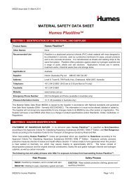
The <strong>JellyFish®</strong> <strong>filter</strong> and components are depicted in<br />
Figure 1 below.<br />
<strong>JellyFish®</strong> <strong>filter</strong><br />
• As an option, the inlet pipe can be located below the<br />
deck for drainage networks with deep invert levels.<br />
In these systems, a deflector plate is installed across<br />
the inlet pipe to induce tangential water flow<br />
through the channel between the chamber wall and<br />
separator skirt.<br />
Figure 1 – <strong>JellyFish®</strong> <strong>filter</strong> components<br />
Maintenance access wall<br />
High-flow cartridges<br />
Inlet<br />
Backwash pool<br />
Outlet<br />
Draindown cartridge<br />
Cartridge deck<br />
Separator skirt<br />
<strong>JellyFish®</strong> <strong>filter</strong> 3
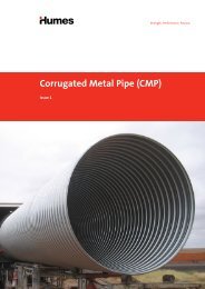
Membrane filtration cartridge<br />
Figure 2 – <strong>JellyFish®</strong> membrane filtration cartridge<br />
The <strong>JellyFish®</strong> <strong>filter</strong> utilises multiple lightweight<br />
membrane filtration cartridges. Each cartridge consists of<br />
multiple removable <strong>filter</strong> elements (“filtration tentacles”)<br />
attached to a cartridge head plate. Each filtration<br />
tentacle consists of a central perforated tube surrounded<br />
by a specialised membrane. A removable oil-resistant<br />
polymeric gasket provides a watertight seal between the<br />
cartridge and the deck. A <strong>JellyFish®</strong> membrane filtration<br />
cartridge is depicted in Figure 2.<br />
Tentacles<br />
Head plate<br />
Attachment<br />
nuts<br />
Lifting eyes<br />
Gasket<br />
The cartridge length is 1,372 mm. The dry weight of<br />
a new cartridge is less than 9 kg, and the wet weight<br />
of a used cartridge is less than 23 kg. No heavy lifting<br />
equipment is required during exchange.<br />
The filtration tentacle membranes provide a large surface<br />
area, resulting in high flow and suspended sediment<br />
removal capacities. A typical <strong>JellyFish®</strong> cartridge with<br />
11 filtration tentacles has 35.4 m 2 of membrane<br />
surface area. Hydraulic testing on clean <strong>filter</strong> cartridges<br />
demonstrated a flow rate of 11.3 L/s at 455 mm of<br />
driving head.<br />
Extensive independent field testing, including testing<br />
at an urban site with high intensity rainfall and runoff,<br />
has demonstrated consistently high pollutant removal<br />
performance with a conservative design flow rate of<br />
5 L/s for the high-flow cartridges and 2.5 L/s for the<br />
draindown cartridges.<br />
These values translate to a conservative design<br />
membrane filtration flux rate (flow per unit surface area)<br />
of 0.14 L/s/m 2 for the high-flow cartridge and 0.07 L/s/m 2<br />
for the draindown cartridge.<br />
In addition, the filtration membrane has been treated<br />
to allow biofilm to grow but not clog the pores of the<br />
membrane. The flow rating of a particular <strong>JellyFish®</strong> <strong>filter</strong><br />
cartridge is based on the membrane filtration surface<br />
area of the cartridge and data collected from both<br />
laboratory testing and field testing. The cartridge deck<br />
contains apertures for each <strong>filter</strong> cartridge.<br />
4 <strong>JellyFish®</strong> <strong>filter</strong>
System operation<br />
As a tertiary treatment system, the <strong>JellyFish®</strong> <strong>filter</strong><br />
is designed to be an “offline” structure, as part of a<br />
treatment train. For effective operation, the system<br />
requires a difference in elevation between upstream and<br />
downstream water levels. Typically, a minimum 455 mm<br />
of driving head is designed into the system but may<br />
vary from 305 mm to 610 mm depending on specific<br />
site requirements.<br />
The <strong>JellyFish®</strong> <strong>filter</strong> uses gravity, flow rotation and<br />
membrane filtration treatment to remove pollutants<br />
from stormwater runoff. These functions are depicted in<br />
Figure 3 below.<br />
Gravitational forces remove coarse sediment (generally<br />
>50 microns), particulate-bound pollutants (nutrients,<br />
toxic metals, hydrocarbons), free oil and floatable<br />
trash and debris (that may bypass upstream primary<br />
treatment devices). Large, heavy particles fall to the sump<br />
(sedimentation) and low specific gravity pollutants rise to<br />
the surface (floatation) behind the MAW.<br />
Treatment begins when flow enters the system through<br />
the inlet pipe (standard). Below-deck inlet pipes are<br />
offered as an option. Influent enters the MAW zone and<br />
passes through a large opening in the deck to the lower<br />
chamber. The large deck opening and change in flow<br />
direction attenuate the influent flow velocity. Buoyant<br />
pollutants remain on the surface in the MAW zone.<br />
<strong>JellyFish®</strong> <strong>filter</strong><br />
Figure 3 – <strong>JellyFish®</strong> <strong>filter</strong> functions<br />
Inlet<br />
Outlet<br />
Gravitational<br />
particles settling<br />
Flow rotation<br />
Membrane<br />
filtration<br />
<strong>JellyFish®</strong> <strong>filter</strong> 5
Flow into the lower chamber must then pass tangentially<br />
around the separator skirt protecting the cartridges<br />
and increasing the flowpath length. Coarse sediment<br />
settles out of the MAW zone into the sump. As water<br />
flows tangentially around the separator skirt in the<br />
lower chamber, the large opening in the bottom of the<br />
separator skirt and upward change in direction further<br />
reduces flow velocity and enhances particle separation.<br />
As a result, sediment settles in the sump.<br />
Flows pass through the cartridge in the filtration zone.<br />
Each <strong>filter</strong> cartridge consists of multiple tentacles.<br />
Hydraulic pressure across the entire membrane surface<br />
area causes water to penetrate the filtration tentacles.<br />
Water enters the membrane pores radially and deposits<br />
fine particulates on the exterior membrane surface.<br />
Filtered water flows into the centre drain tube of each<br />
tentacle, the water then flows upward and out the top.<br />
Water exiting the top of the tentacles combines under<br />
the lid, where the combined flow exits the cartridge<br />
through the orifice with a pulsating fountain effect<br />
into the backwash pool. When the water level in the<br />
backwash pool exceeds the weir height it overflows to<br />
the outlet pipe.<br />
Outside the backwash pool, the draindown cartridge<br />
provides treatment at a reduced flow rate (2.5 L/s) and<br />
allows the treated water captured in the backwash pool<br />
to return through the cartridges and balance water<br />
pressure as the storm event ends.<br />
As particles build up on the external membrane surface,<br />
the pores progressively become smaller. This process,<br />
referred to as “<strong>filter</strong> ripening”, significantly improves<br />
the removal efficiency relative to a brand new or clean<br />
membrane. Filter ripening accounts for the ability of<br />
the <strong>JellyFish®</strong> <strong>filter</strong> to remove particles finer than the<br />
nominal pore size. An animation of the <strong>JellyFish®</strong> <strong>filter</strong><br />
operation and maintenance is available at humes.com.au.<br />
Self-cleaning functions<br />
The <strong>JellyFish®</strong> <strong>filter</strong> utilises several self-cleaning<br />
processes to remove accumulated sediment from the<br />
external surfaces of the filtration membranes, including<br />
automatic backwash of the high-flow cartridges,<br />
vibrational pulses, and gravity. These processes have<br />
been confirmed by more than 12 months of full<br />
scale prototype testing. Combined, these processes<br />
significantly extend the cartridge life, maintenance<br />
interval and reduce life-cycle costs.<br />
Automatic backwash occurs with the high-flow<br />
cartridges at the end of each runoff event. This can occur<br />
multiple times during a single storm event as intensity<br />
and driving head varies. As the inflow subsides and<br />
driving head decreases, water in the backwash pool<br />
reverses flow direction and automatically backwashes<br />
the high-flow cartridges, removing sediment from the<br />
membrane surfaces. Water in the lower chamber (below<br />
deck) is displaced through the draindown cartridges.<br />
Vibrational pulses occur as a result of complex and<br />
variable pressure and flow direction conditions that<br />
arise in the deck during operation. During forward flow<br />
a stream of <strong>filter</strong>ed water exits the top of each filtration<br />
cartridge and encounters resistance from the turbulent<br />
pool of water in the backwash pool. Water is forced<br />
through the cartridge lid orifice into the backwash pool<br />
with a pulsating fountain effect. The resulting pulses<br />
transmit vibrations through the deck to the membranes,<br />
thereby dislodging accumulated sediment. The effect<br />
is pronounced at higher flow rates, and influences<br />
all cartridges.<br />
Accumulated sediment on the membranes will settle<br />
under gravity both during inflow events and inter-event<br />
dry periods. As fine particles form into larger masses<br />
on the membrane surface, adhesion to the membrane<br />
surface lessens, and sediment sheds away from the<br />
membrane. Chemical processes and biofilm effects also<br />
play a role.<br />
6 <strong>JellyFish®</strong> <strong>filter</strong>
System performance<br />
The <strong>JellyFish®</strong> <strong>filter</strong> has been designed to provide tertiary<br />
level treatment and may be combined with a Gross<br />
Pollutant Trap (GPT) as part of a treatment train to<br />
optimise overall performance.<br />
Treatment efficiency<br />
Inlet and outlet pipes<br />
An above-deck inlet pipe configuration is standard<br />
for the <strong>JellyFish®</strong> <strong>filter</strong> and an optional below-deck<br />
inlet configuration is available on request. Specific site<br />
constraints generally determine the configuration that<br />
is most favourable. In both configurations, the invert<br />
level of the outlet pipe is identical to the cartridge<br />
deck elevation.<br />
<strong>JellyFish®</strong> <strong>filter</strong><br />
Extensive research of the <strong>JellyFish®</strong> <strong>filter</strong> has proven<br />
its performance under Australian laboratory, US field<br />
conditions and Australian field conditions. Field testing in<br />
the United States has received independent verification<br />
under the stringent New Jersey Corporation for Advanced<br />
Technology (NJCAT) protocol. The results are summarised<br />
in Table 1 below<br />
Table 1 – <strong>JellyFish®</strong> <strong>filter</strong> performance summary<br />
Pollutant<br />
Median reduction<br />
TSS 89%<br />
TP 67%<br />
TN 48%<br />
Cu 61%<br />
Zn 91%<br />
Total oil and grease 62%<br />
Reference: University of Florida (2011) and West Ipswich (2014 ).<br />
<strong>JellyFish®</strong> <strong>filter</strong> 7
System options<br />
The <strong>JellyFish®</strong> <strong>filter</strong> can be customised to suit your project<br />
requirements. As each treatment train is unique and<br />
units are designed to match surface levels, please contact<br />
<strong>Humes</strong> for assistance, however, Table 2 below can be<br />
used as a guide.<br />
Table 2 – <strong>JellyFish®</strong> <strong>filter</strong> model range and details<br />
<strong>JellyFish®</strong><br />
model<br />
Number of highflow<br />
cartridges<br />
JF1200-1-1 1<br />
Number of<br />
draindown<br />
cartridges<br />
Inlet pipe<br />
diameters (mm)<br />
Treatment flow<br />
(L/s)<br />
JF1200-2-1 2 12.5<br />
JF1800-3-1 3 17.5<br />
1<br />
JF1800-4-1 4 22.5<br />
150 - 225<br />
JF1800-5-1 5 27.5<br />
JF1800-6-1 6 32.5<br />
JF2400-6-2 6<br />
JF2400-7-2 7 40.0<br />
JF2400-8-2 8<br />
JF2400-9-2 9 50.0<br />
JF2400-10-2 10 55.0<br />
JF3000-11-3 11<br />
62.5<br />
3<br />
JF3000-12-3 12 225 - 300<br />
67.5<br />
JF3000-12-4 12<br />
JF3000-13-4 13 75.0<br />
JF3000-14-4 14 80.0<br />
JF3000-15-4 15 85.0<br />
4<br />
JF3000-16-4 16<br />
90.0<br />
JF3000-17-4 17 95.0<br />
JF3000-18-4 18 100.0<br />
JF3000-19-4 19 105.0<br />
JF3600-20-5 20<br />
JF3600-21-5 21 117.5<br />
300 - 375<br />
JF3600-22-5 22 122.5<br />
2<br />
7.5<br />
35.0<br />
45.0<br />
70.0<br />
112.5<br />
JF3600-23-5 23 127.5<br />
5<br />
JF3600-24-5 24 132.5<br />
JF3600-25-5 25 137.5<br />
JF3600-26-5 26 142.5<br />
JF3600-27-5 27 147.5<br />
Nominal<br />
structure<br />
diameter (mm)<br />
1,200<br />
1,800<br />
2,400<br />
3,000<br />
3,600<br />
Note: Designers should allow for upstream and downstream bypass pits and a bypass pipe link in a triangular configuration.<br />
8 <strong>JellyFish®</strong> <strong>filter</strong>
Design information<br />
The <strong>JellyFish®</strong> <strong>filter</strong> has many flexible design features to<br />
accommodate a wide range of specific site requirements<br />
and constraints. Please contact <strong>Humes</strong> for assistance.<br />
Configurations and design capacities<br />
For the standard above-deck inlet pipe configuration, the<br />
invert elevation of the inlet pipe is typically set 150 mm<br />
higher than the invert elevation of the outlet pipe. This<br />
generally ensures that the inlet pipe will drain completely<br />
after each rainfall/runoff event, while providing sufficient<br />
volume within the MAW zone for surface accumulation<br />
of floatables below the inlet pipe. The elevation of the<br />
inlet pipe can be varied as required.<br />
<strong>JellyFish®</strong> <strong>filter</strong><br />
Design flow capacities and pollutant capacities for<br />
standard <strong>JellyFish®</strong> <strong>filter</strong> configurations are shown in<br />
Table 2 on the previous page.<br />
The <strong>JellyFish®</strong> <strong>filter</strong> standard model numbers provide<br />
information about the manhole inside diameter and<br />
cartridge counts for high-flow and draindown cartridges.<br />
For example, the <strong>JellyFish®</strong> <strong>filter</strong> model number<br />
JF1800-5-1 is an 1,800 mm diameter structure with five<br />
high-flow cartridges and one draindown cartridge.<br />
The <strong>JellyFish®</strong> <strong>filter</strong> can accommodate a range of angles<br />
between the inlet and outlet pipes. Standard outlet pipe<br />
locations are within a 180° span about the circumference<br />
of the structure (refer to Figure 4 below). The separation<br />
angle relationship of the inlet pipe to the outlet pipe can<br />
vary from 90 to 270 degrees to provide maximum design<br />
flexibility. Contact <strong>Humes</strong> Water Solutions for assistance<br />
with angles outside this range. The <strong>JellyFish®</strong> <strong>filter</strong> can be<br />
installed at a range of depths of cover.<br />
With systems using an external bypass from an upstream<br />
diversion structure, the driving head is calculated as the<br />
difference in elevation between the top of the diversion<br />
structure weir and the invert of the <strong>JellyFish®</strong> <strong>filter</strong> outlet<br />
pipe. A minimum of 455 mm is required to drive the flow<br />
through the <strong>JellyFish®</strong> <strong>filter</strong> at the rates shown in Table 2.<br />
Figure 4 – Typical <strong>JellyFish®</strong> <strong>filter</strong> outlet locations<br />
Inlet<br />
Outlet<br />
Recommended design flows of 5 L/s for high flow<br />
cartridges and 2.5 L/s for draindown cartridges are to<br />
ensure longevity of the <strong>filter</strong>.<br />
Submerged or backwater conditions may be<br />
accommodated in some circumstances and assistance<br />
from <strong>Humes</strong> engineers is recommended.<br />
<strong>JellyFish®</strong> <strong>filter</strong> 9
Bypass design<br />
The <strong>JellyFish®</strong> <strong>filter</strong> should be designed in an offline<br />
configuration for most catchments. All stormwater <strong>filter</strong><br />
systems will perform for a longer duration between<br />
required maintenance services when designed and<br />
applied in offline configurations. A standard offline<br />
configuration has an external bypass that uses an<br />
upstream diversion structure. The elevation difference<br />
between the top of the diversion structure and the<br />
<strong>JellyFish®</strong> <strong>filter</strong> outlet pipe invert should be a minimum<br />
of 455 mm. Excess flow that overflows the diversion,<br />
bypasses the <strong>JellyFish®</strong> <strong>filter</strong>.<br />
For smaller sites an online configuration might be more<br />
suitable. In these cases, an optional internal bypass<br />
pressure relief pipe(s) can be placed in one or multiple<br />
cartridge receptacles within the <strong>JellyFish®</strong> <strong>filter</strong>.<br />
The pressure relief pipe height and diameter can be<br />
varied to accommodate the design peak flow rate and<br />
system driving head requirements. For these systems, the<br />
driving head is calculated as the difference in elevation<br />
between the top of the pressure relief pipe and the invert<br />
of the outlet pipe.<br />
When the internal bypass option is utilised, peak flow<br />
rates receive membrane filtration treatment up to the<br />
filtration design flow rate, with the balance of the peak<br />
flow receiving primary treatment only. In these cases,<br />
increased sump depth may be required to increase<br />
sediment storage capacity and to minimise re-suspension<br />
of previously captured sediment at peak flow rates.<br />
It is also possible to configure this arrangement using<br />
a single diversion structure. Contact <strong>Humes</strong> for design<br />
assistance.<br />
Figure 5 – <strong>JellyFish®</strong> <strong>filter</strong> offline arrangement without diversion weir<br />
Diversion chamber inlet<br />
Low flow<br />
<strong>JellyFish®</strong> unit outlet I.L.<br />
is 455 mm lower than<br />
I.L. of high flow bypass<br />
inlet<br />
Low flow<br />
High flow bypass<br />
Bypass inlet I.L. is 455 mm<br />
higher than <strong>JellyFish®</strong><br />
unit outlet<br />
Diversion chamber<br />
<strong>JellyFish®</strong> unit<br />
Collection chamber<br />
Figure 6 – <strong>JellyFish®</strong> <strong>filter</strong> offline arrangement with diversion weir<br />
Diversion chamber inlet<br />
<strong>JellyFish®</strong> unit outlet I.L.<br />
is 455 mm lower than<br />
top of weir wall<br />
Low flow<br />
Low flow<br />
High flow bypass<br />
Top of weir is 455 mm<br />
higher than I.L. of<br />
<strong>JellyFish®</strong> unit outlet<br />
Diversion chamber<br />
<strong>JellyFish®</strong> unit<br />
Collection chamber<br />
10 <strong>JellyFish®</strong> <strong>filter</strong>
Dry sump option<br />
The <strong>JellyFish®</strong> <strong>filter</strong> can be supplied with a dry sump<br />
option by way of <strong>filter</strong>ing the water collected in the sump<br />
during a rainfall event to an offline soak well.<br />
The captured water is <strong>filter</strong>ed with a horizontally<br />
positioned <strong>filter</strong> “tentacle” that is covered by a stainless<br />
steel shroud for protection at the sump invert.<br />
The release of <strong>filter</strong>ed water is controlled by using an<br />
Figure 7 – <strong>JellyFish®</strong> <strong>filter</strong> with dry sump option<br />
Concrete cover<br />
Upper converter<br />
surround ring<br />
Lower converter<br />
surround ring<br />
Maintenance access wall<br />
Inlet pipe<br />
Manholes<br />
Treatment<br />
chamber<br />
Outlet pipe<br />
Drainage channel<br />
<strong>JellyFish®</strong> <strong>filter</strong><br />
orifice plate at the exit of the sump, which is sized<br />
Separator skirt<br />
to match the required hydraulic conductivity of the<br />
receiving media.<br />
Filter cartridges<br />
Base unit<br />
Submerged (tidal/tailwater) installations<br />
The <strong>JellyFish®</strong> <strong>filter</strong> is designed to function optimally<br />
under free-surface flow conditions. For systems that<br />
may experience submerged or backwater conditions due<br />
to tailwater or tidal effects, driving head calculations<br />
must account for water elevation during the backwater<br />
condition. The <strong>JellyFish®</strong> <strong>filter</strong> treatment functions<br />
Perforated shroud<br />
Filter medium<br />
One-way valve<br />
Stop valve<br />
uPVC pipe<br />
will continue to operate despite backwater conditions.<br />
A customised design will be required to ensure litter<br />
capture and backwash. Contact <strong>Humes</strong> for assistance.<br />
Series <strong>JellyFish®</strong> <strong>filter</strong><br />
For sites with water quality treatment flow rates that<br />
exceed the design flow rate of the largest standard<br />
<strong>JellyFish®</strong> <strong>filter</strong> model, custom systems can be<br />
designed that hydraulically connect multiple <strong>JellyFish®</strong><br />
<strong>filter</strong>s in series. For any design questions or custom<br />
modifications, contact <strong>Humes</strong> for assistance.<br />
<strong>JellyFish®</strong> <strong>filter</strong> 11
System installation<br />
The <strong>JellyFish®</strong> <strong>filter</strong> can be installed by a civil or plumbing<br />
contractor in much the same way as a manhole or other<br />
stormwater drainage structures. It is supplied on-site in<br />
separate, easily identifiable components. The upstream<br />
bypass pit and downstream junction pit are supplied<br />
separately.<br />
The <strong>JellyFish®</strong> <strong>filter</strong> is lowered into place by a crane<br />
or excavator, the components interlock and a tapered<br />
surround can be supplied and rotated to match a surface<br />
grade (if the system is located in road pavement). The<br />
system arrives to the site with the internal parts fully<br />
assembled.<br />
Inspection and maintenance<br />
For inspection and maintenance information, please refer<br />
to the <strong>JellyFish®</strong> <strong>filter</strong> owner’s <strong>manual</strong>.<br />
An animation of the <strong>JellyFish®</strong> <strong>filter</strong> operation and<br />
maintenance is available at humes.com.au.<br />
Replacement parts<br />
Replacement parts for the <strong>JellyFish®</strong> <strong>filter</strong> can be<br />
ordered by contacting <strong>Humes</strong> at ph 1300 361 601 or<br />
info@humes.com.au.<br />
12 <strong>JellyFish®</strong> <strong>filter</strong>
Appendices<br />
<strong>JellyFish®</strong> <strong>filter</strong> standard drawings<br />
<strong>JellyFish®</strong> <strong>filter</strong> inspection and maintenance log<br />
<strong>JellyFish®</strong> <strong>filter</strong><br />
<strong>JellyFish®</strong> <strong>filter</strong> 13
Holcim (Australia) Pty Ltd<br />
TECHNICAL SERVICES<br />
BRISBANE, QUEENSLAND
Holcim (Australia) Pty Ltd<br />
TECHNICAL SERVICES<br />
BRISBANE, QUEENSLAND
Holcim (Australia) Pty Ltd<br />
TECHNICAL SERVICES<br />
BRISBANE, QUEENSLAND
Holcim (Australia) Pty Ltd<br />
TECHNICAL SERVICES<br />
BRISBANE, QUEENSLAND
Holcim (Australia) Pty Ltd<br />
TECHNICAL SERVICES<br />
BRISBANE, QUEENSLAND
<strong>Humes</strong><br />
Holcim (Australia) Pty Ltd<br />
ABN 87 099 732 297<br />
18 Little Cribb st<br />
Milton QLD 4064<br />
Australia<br />
<strong>JellyFish®</strong> <strong>filter</strong> inspection and maintenance log<br />
Phone (07) 3364 2800<br />
Fax (07) 3364 2835<br />
www.humes.com.au<br />
Owner:<br />
Location:<br />
GPS coordinates:<br />
<strong>JellyFish®</strong> <strong>filter</strong> model number:<br />
Land use: Commercial: Industrial: Service station:<br />
Road/highway:<br />
Mine site:<br />
Residential:<br />
Other:<br />
Date:<br />
Time:<br />
Inspector<br />
Maintenance contractor<br />
Visible oil present (Y/N)<br />
Oil quantity removed (Y/N)<br />
Floatable debris present (Y/N)<br />
Floatable debris removed (Y/N)<br />
Water depth in backwash pool<br />
Draindown cartridges backflushed (Y/N)<br />
Draindown cartridges externally rinsed<br />
and re-commissioned (Y/N)<br />
New tentacles put on draindown<br />
cartridges (Y/N)<br />
High-flow cartridges backflushed (Y/N)<br />
High-flow cartridges externally rinsed<br />
and re-commissioned (Y/N)<br />
New tentacles put on high-flow<br />
cartridges (Y/N)<br />
Sediment depth<br />
Sediment removed (Y/N)<br />
Cartridge lids intact (Y/N)<br />
Other comments:<br />
(Deck condition, blockages of upstream/<br />
downstream junctions, skirts, etc..)
Contact information<br />
National sales 1300 361 601<br />
humes.com.au<br />
info@humes.com.au<br />
Head Office<br />
New South Wales<br />
Tasmania<br />
18 Little Cribb St<br />
Milton 4064 QLD<br />
Ph: (07) 3364 2800<br />
Fax: (07) 3364 2963<br />
Queensland<br />
Ipswich/Brisbane<br />
Ph: (07) 3814 9000<br />
Fax: (07) 3814 9014<br />
Rockhampton<br />
Ph: (07) 4924 7900<br />
Fax: (07) 4924 7901<br />
Townsville<br />
Ph: (07) 4758 6000<br />
Fax: (07) 4758 6001<br />
Grafton<br />
Ph: (02) 6644 7666<br />
Fax: (02) 6644 7313<br />
Newcastle<br />
Ph: (02) 4032 6800<br />
Fax: (02) 4032 6822<br />
Sydney<br />
Ph: (02) 9832 5555<br />
Fax: (02) 9625 5200<br />
Tamworth<br />
Ph: (02) 6763 7300<br />
Fax: (02) 6763 7301<br />
Victoria<br />
Echuca<br />
Ph: (03) 5480 2371<br />
Fax: (03) 5482 3090<br />
Melbourne<br />
Ph: (03) 9360 3888<br />
Fax: (03) 9360 3887<br />
Launceston<br />
Ph: (03) 6335 6300<br />
Fax: (03) 6335 6330<br />
South Australia<br />
Adelaide<br />
Ph: (08) 8168 4544<br />
Fax: (08) 8168 4549<br />
Western Australia<br />
Gnangara<br />
Ph: (08) 9302 8000<br />
Fax: (08) 9309 1625<br />
Perth<br />
Ph: (08) 9351 6999<br />
Fax: (08) 9351 6977<br />
Northern Territory<br />
Darwin<br />
Ph: (08) 8984 1600<br />
Fax: (08) 8984 1614
National sales 1300 361 601<br />
humes.com.au<br />
info@humes.com.au<br />
A Division of Holcim Australia<br />
This brochure supersedes all previous literature on this subject. As the specifications and details contained in this publication may change please<br />
check with <strong>Humes</strong> Customer Service for confirmation of current issue. This document is provided for information only. Users are advised to<br />
make their own determination as to the suitability of this information or any <strong>Humes</strong> product for their own specific circumstances. We accept<br />
no responsibility for any loss or damage resulting from any person acting on this information. <strong>Humes</strong> is a registered business name of Holcim<br />
(Australia) Pty Ltd. The JellyFish <strong>filter</strong> is manufactured, marketed, and sold by <strong>Humes</strong> under licence from Imbrium Systems Inc, Canada. JellyFish<br />
is a registered trademark of Imbrium Systems Inc, Canada and is used in Australia under license. <strong>Humes</strong> is a registered trademark of Holcim<br />
Australia Pty Limited. JellyFish is registered under Australian Patent No. 2008286748, US Patent Application No. 11/839,303 and 12/014,888 and<br />
International Publication No. WO 2009/023832 A1.<br />
© February 2015 Holcim (Australia) Pty Ltd ABN 87 099 732 297. All rights reserved. This guide or any part of it may not be reproduced without<br />
prior written consent of Holcim.