HYDRAULICS OF PRECAST CONCRETE CONDUITS ... - Humes
HYDRAULICS OF PRECAST CONCRETE CONDUITS ... - Humes
HYDRAULICS OF PRECAST CONCRETE CONDUITS ... - Humes
You also want an ePaper? Increase the reach of your titles
YUMPU automatically turns print PDFs into web optimized ePapers that Google loves.
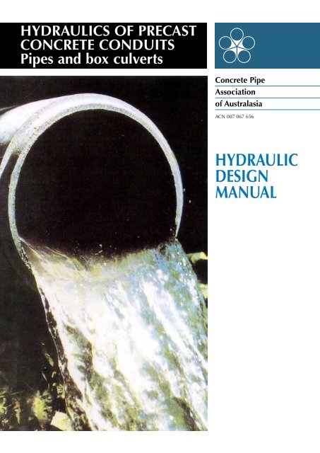
<strong>HYDRAULICS</strong> <strong>OF</strong> <strong>PRECAST</strong><strong>CONCRETE</strong> <strong>CONDUITS</strong>Pipes and box culvertsConcrete PipeAssociationof AustralasiaACN 007 067 656HYDRAULICDESIGNMANUAL
<strong>HYDRAULICS</strong> <strong>OF</strong> <strong>PRECAST</strong> <strong>CONCRETE</strong> <strong>CONDUITS</strong>SECTION 11. FLOW <strong>OF</strong> WATER IN <strong>PRECAST</strong> <strong>CONCRETE</strong> <strong>CONDUITS</strong>1.1 PHYSICAL PROPERTIES <strong>OF</strong> WATER1.2 FULL FLOW1.2.1 THE ENERGY LINE1.2.2 ENERGY LOSSES AT CROSS SECTIONAL CHANGES1.2.3 ENERGY LOSS AT UNIFORM FLOW1.2.3.1 GENERAL1.3 PART-FULL FLOW1.2.3.2 THE COLEBROOK-WHITE EQUATION1.2.3.3 OTHER ENERGY LOSS EQUATIONS1.3.1 UNIFORM FLOW1.3.1.1 ENERGY LOSSES AT SECTIONAL CHANGES1.3.1.2 UNIFORM ENERGY LOSSES1.3.1.3 FLOW VELOCITY IN CLOSED <strong>CONDUITS</strong>1.3.2 NON UNIFORM FLOW1.3.2.1 GENERAL1.4 BOUNDARYSHEAR1.5 WATER HAMMER1.3.2.2 CRITICAL DEPTH1.3.2.3 CRITICAL SLOPE1.3.2.4 THE HYDRAULIC JUMP1.5.1 THE NATURE <strong>OF</strong> WATER HAMMER1.5.2 VALVE CLOSURE1.5.3 PUMP STOPPAGE1.5.4 WAVESPEED1.6 REFERENCESPage 4
<strong>HYDRAULICS</strong> <strong>OF</strong> <strong>PRECAST</strong> <strong>CONCRETE</strong> <strong>CONDUITS</strong>SECTION 1Page 5
<strong>HYDRAULICS</strong> <strong>OF</strong> <strong>PRECAST</strong> <strong>CONCRETE</strong> <strong>CONDUITS</strong>SECTION 1Page 7
<strong>HYDRAULICS</strong> <strong>OF</strong> <strong>PRECAST</strong> <strong>CONCRETE</strong> <strong>CONDUITS</strong>SECTION 1Page 8
<strong>HYDRAULICS</strong> <strong>OF</strong> <strong>PRECAST</strong> <strong>CONCRETE</strong> <strong>CONDUITS</strong>SECTION 1Page 9
Page 10
Page 11
Page 12
Page 13
<strong>HYDRAULICS</strong> <strong>OF</strong> <strong>PRECAST</strong> <strong>CONCRETE</strong> <strong>CONDUITS</strong>SECTION 1Page 14
<strong>HYDRAULICS</strong> <strong>OF</strong> <strong>PRECAST</strong> <strong>CONCRETE</strong> <strong>CONDUITS</strong>SECTION 1Page 15
<strong>HYDRAULICS</strong> <strong>OF</strong> <strong>PRECAST</strong> <strong>CONCRETE</strong> <strong>CONDUITS</strong>SECTION 1Page 16
<strong>HYDRAULICS</strong> <strong>OF</strong> <strong>PRECAST</strong> <strong>CONCRETE</strong> <strong>CONDUITS</strong>SECTION 1Page 17
<strong>HYDRAULICS</strong> <strong>OF</strong> <strong>PRECAST</strong> <strong>CONCRETE</strong> <strong>CONDUITS</strong>SECTION 1Page 18
<strong>HYDRAULICS</strong> <strong>OF</strong> <strong>PRECAST</strong> <strong>CONCRETE</strong> <strong>CONDUITS</strong>SECTION 11.6 REFERENCES[1.1] Developments in Water Science Vol. 6 “PipelineDesign for Water Engineers”. By David Stephenson.Elsevier 1976.[1.2.] Australian Standard 2200-1978. “Design Charts forWater Supply and Sewerage”.[1.3.] C.F. Colebrook “Turbulent Flow in Pipes with ParticularReference to the Transition Region between theSmooth and Rough Pipe Laws”. J. Inst. Civ. Eng. 1939Vol.11 PP 133-156.[1.4.] “Resistance to flow in two types of concrete pipe”.Lorenz G. Straub, Charles E. Bowers and Meir Puch.St. Anthony Falls Hydraulic Laboratory. TechnicalPaper No.22 Series B. 1960.[1:5.] “Hydraulik”. A.E. Bretting (In Danish) Copenhagen1960 P241.[1.6.] “Hydraulics of Open Channels”. B.A. Bakhmeteff.Engineering Societies Monograph, McGraw-Hill BookCo. 1932.[1.7.] “Water Hammer – Problems and Solutions”. B.B.Sharp, Edward Arnold, 1981.[1.8.] “Water Hammer Analysis”, J. Parmakian, Dover,1963.[1.9.] “Water Hammer in Pumping Systems”, B.B. Sharpand H.R. Graze, Pump Technical Congress, A.P.M.A.,University of Melbourne, Nov.1980.Page 19
<strong>HYDRAULICS</strong> <strong>OF</strong> <strong>PRECAST</strong> <strong>CONCRETE</strong> <strong>CONDUITS</strong>SECTION 22. STORMWATER RUN<strong>OF</strong>F2.1 INTRODUCTION2.2 RAINFALL2.2.1 FREQUENCY2.2.2 POINT MEASUREMENT <strong>OF</strong> RAINFALL APPLIED TO AN AREA2.3 PEAK FLOW FORMULA2.3.1 COEFFICIENT <strong>OF</strong> RUN<strong>OF</strong>F2.3.2 TIME <strong>OF</strong> CONCENTRATION2.3.3 LIMITATIONS TO PEAK FLOW FORMULA2.3.4 TANGENT CHECK2.4 EXAMPLES2.4.1 URBAN CATCHMENT2.4.2 RURAL CATCHMENT2.4.3 LARGE CATCHMENT2.5 REFERENCESPage 20
<strong>HYDRAULICS</strong> <strong>OF</strong> <strong>PRECAST</strong> <strong>CONCRETE</strong> <strong>CONDUITS</strong>SECTION 2Page 21
<strong>HYDRAULICS</strong> <strong>OF</strong> <strong>PRECAST</strong> <strong>CONCRETE</strong> <strong>CONDUITS</strong>SECTION 2Page 22
<strong>HYDRAULICS</strong> <strong>OF</strong> <strong>PRECAST</strong> <strong>CONCRETE</strong> <strong>CONDUITS</strong>SECTION 2Page 23
<strong>HYDRAULICS</strong> <strong>OF</strong> <strong>PRECAST</strong> <strong>CONCRETE</strong> <strong>CONDUITS</strong>SECTION 2Page 24
<strong>HYDRAULICS</strong> <strong>OF</strong> <strong>PRECAST</strong> <strong>CONCRETE</strong> <strong>CONDUITS</strong>SECTION 2Page 25
<strong>HYDRAULICS</strong> <strong>OF</strong> <strong>PRECAST</strong> <strong>CONCRETE</strong> <strong>CONDUITS</strong>SECTION 2Page 26
<strong>HYDRAULICS</strong> <strong>OF</strong> <strong>PRECAST</strong> <strong>CONCRETE</strong> <strong>CONDUITS</strong>SECTION 2Page 27
<strong>HYDRAULICS</strong> <strong>OF</strong> <strong>PRECAST</strong> <strong>CONCRETE</strong> <strong>CONDUITS</strong>SECTION 2Page 28
<strong>HYDRAULICS</strong> <strong>OF</strong> <strong>PRECAST</strong> <strong>CONCRETE</strong> <strong>CONDUITS</strong>SECTION 2Page 29
<strong>HYDRAULICS</strong> <strong>OF</strong> <strong>PRECAST</strong> <strong>CONCRETE</strong> <strong>CONDUITS</strong>SECTION 33. CULVERTS3.1 INTRODUCTION3.1.1 TYPES <strong>OF</strong> CULVERT FLOW CONTROL3.1.1.1. FLOW WITH INLET CONTROL3.1.1.2 FLOW WITH OUTLET CONTROL3.1.1.3 DETERMINATION <strong>OF</strong> OPERATING CONDITION3.1.2 HEADWATER3.1.3 TAILWATER3.1.4 FREEBOARD3.2 CULVERTS WITH INLET CONTROL3.3 CULVERTS WITH OUTLET CONTROL3.3.1 CULVERTS FLOWING FULL3.3.2 CULVERTS NOT FLOWING FULL3.4 FLOW VELOCITY3.4.1 INLET CONTROL3.4.2 OUTLET CONTROL3.4.3 EROSION3.4.4 SILTATION3.5 CULVERTSHAPE3.6 MINIMUM ENERGY CULVERTS3.7 EXAMPLES3.7.1 PIPE SOLUTION (INLET CONTROL)3.7.2 BOX CULVERT SOLUTION (INLET CONTROL)3.7.3 PIPE SOLUTION (OUTLET CONTROL)3.7.4 BOX CULVERT SOLUTION (OUTLET CONTROL)3.7.5 MINIMUM ENERGY CULVERT3.8 REFERENCESPage 30
<strong>HYDRAULICS</strong> <strong>OF</strong> <strong>PRECAST</strong> <strong>CONCRETE</strong> <strong>CONDUITS</strong>SECTION 3Page 31
<strong>HYDRAULICS</strong> <strong>OF</strong> <strong>PRECAST</strong> <strong>CONCRETE</strong> <strong>CONDUITS</strong>SECTION 3Page 32
<strong>HYDRAULICS</strong> <strong>OF</strong> <strong>PRECAST</strong> <strong>CONCRETE</strong> <strong>CONDUITS</strong>SECTION 3Page 33
<strong>HYDRAULICS</strong> <strong>OF</strong> <strong>PRECAST</strong> <strong>CONCRETE</strong> <strong>CONDUITS</strong>SECTION 3Page 34
<strong>HYDRAULICS</strong> <strong>OF</strong> <strong>PRECAST</strong> <strong>CONCRETE</strong> <strong>CONDUITS</strong>SECTION 3Page 35
<strong>HYDRAULICS</strong> <strong>OF</strong> <strong>PRECAST</strong> <strong>CONCRETE</strong> <strong>CONDUITS</strong>SECTION 3Page 36
<strong>HYDRAULICS</strong> <strong>OF</strong> <strong>PRECAST</strong> <strong>CONCRETE</strong> <strong>CONDUITS</strong>SECTION 3Page 37
<strong>HYDRAULICS</strong> <strong>OF</strong> <strong>PRECAST</strong> <strong>CONCRETE</strong> <strong>CONDUITS</strong>SECTION 3Page 38
<strong>HYDRAULICS</strong> <strong>OF</strong> <strong>PRECAST</strong> <strong>CONCRETE</strong> <strong>CONDUITS</strong>SECTION 3Page 39
<strong>HYDRAULICS</strong> <strong>OF</strong> <strong>PRECAST</strong> <strong>CONCRETE</strong> <strong>CONDUITS</strong>SECTION 3Page 40
<strong>HYDRAULICS</strong> <strong>OF</strong> <strong>PRECAST</strong> <strong>CONCRETE</strong> <strong>CONDUITS</strong>SECTION 3Page 41
<strong>HYDRAULICS</strong> <strong>OF</strong> <strong>PRECAST</strong> <strong>CONCRETE</strong> <strong>CONDUITS</strong>SECTION 3Page 42
<strong>HYDRAULICS</strong> <strong>OF</strong> <strong>PRECAST</strong> <strong>CONCRETE</strong> <strong>CONDUITS</strong>SECTION 44. STORMWATER DRAINAGE SYSTEMS4.1. INTRODUCTION4.1.1 HEAD LOSSES4.1.2 MINIMUM AND MAXIMUM VELOCITIES4.1.3 TOPOGRAPHY4.2 RESISTANCE TO FLOW IN <strong>CONDUITS</strong>4.2.1 STRAIGHT DRAINS4.2.2 CURVED DRAINS4.2.2.1 PIPES4.2.2.2 BOX CULVERTS4.2.3 ACTUAL DIMENSIONS4.3 INLET SHAPE AND CAPACITY4.4 JUNCTION PITS4.4.1 INLET PIT WITH INLET FLOW ONLY4.4.2 JUNCTION PITS WITH INLET AND LATERAL FLOW4.4.3 OTHER PIT TYPES4.4.4 INVERT DROP THROUGH PITS4.5 DEPTH <strong>OF</strong> DRAINS4.6 GUTTER FLOW4.7 STEEP DRAINS4.8 EXAMPLES4.8.1 URBAN CATCHMENTUNDERGROUND DRAINAGE4.8.2 STEEP SLOPES4.9 REFERENCESPage 43
<strong>HYDRAULICS</strong> <strong>OF</strong> <strong>PRECAST</strong> <strong>CONCRETE</strong> <strong>CONDUITS</strong>SECTION 4Page 44
<strong>HYDRAULICS</strong> <strong>OF</strong> <strong>PRECAST</strong> <strong>CONCRETE</strong> <strong>CONDUITS</strong>SECTION 4Page 45
<strong>HYDRAULICS</strong> <strong>OF</strong> <strong>PRECAST</strong> <strong>CONCRETE</strong> <strong>CONDUITS</strong>SECTION 4Page 46
<strong>HYDRAULICS</strong> <strong>OF</strong> <strong>PRECAST</strong> <strong>CONCRETE</strong> <strong>CONDUITS</strong>SECTION 4Page 47
<strong>HYDRAULICS</strong> <strong>OF</strong> <strong>PRECAST</strong> <strong>CONCRETE</strong> <strong>CONDUITS</strong>SECTION 4Page 48
<strong>HYDRAULICS</strong> <strong>OF</strong> <strong>PRECAST</strong> <strong>CONCRETE</strong> <strong>CONDUITS</strong>SECTION 4Page 49
<strong>HYDRAULICS</strong> <strong>OF</strong> <strong>PRECAST</strong> <strong>CONCRETE</strong> <strong>CONDUITS</strong>SECTION 4Page 50
<strong>HYDRAULICS</strong> <strong>OF</strong> <strong>PRECAST</strong> <strong>CONCRETE</strong> <strong>CONDUITS</strong>SECTION 4Page 51
<strong>HYDRAULICS</strong> <strong>OF</strong> <strong>PRECAST</strong> <strong>CONCRETE</strong> <strong>CONDUITS</strong>SECTION 44.9 REFERENCES[4.1] “Urban Road Design Manual” Vol.2 - 1975,Main Roads Department Queensland.[4.2] “Pressure Changes at Storm Drain Junctions”,W.H. Sagster, H.W. Wood, E.T. Smedon andH.C. Bossy. Engineering Series Bulletin No 1,University of Missouri.[4.3] “Concrete Pipe Handbook” (1980 AmericanConcrete Pipe Association).[4.4] “Urban Surface Drainage Design”J.R. Argue, ARRB Regional Symposium,Perth 1979.[4.5] “Gutter Pavement Flow Relationships forRoadway Channels of Moderate or SteepGrade,” W.P. Clarke, P.J. Strode, J.R. Argue,Institute of Technology, South Australia. S.A.Local Government Engineers Conference 1981[4.6] “Stormwater Drainage Design Procedure, theirefficacy in relation to recent technological advance”B.C. Tonkin, P.k. Read, R.l. Williams. LocalGovernment Engineering Conference,August 1981.[4.7] “Road Design Manual”Country Roads Board - Victoria 1974[4.8] ASCE - Manuals and Reports on EngineeringPractice - No.37. “Design and Construction ofSanitary and Storm Sewers”, New York, 1970.Page 52
<strong>HYDRAULICS</strong> <strong>OF</strong> <strong>PRECAST</strong> <strong>CONCRETE</strong> <strong>CONDUITS</strong>SECTION 55. SEPARATE SEWERAGE SYSTEMS5.1 INTRODUCTION5.2 THE DESIGN FLOW5.2.1 DESIGN FLOW COMPONENTS5.3 GRAVITY SEWERS5.3.1 MINIMUM GRADE5.3.2 MAXIMUM GRADE5.4 THE SEWER DIMENSIONS5.4.1 ROUGHNESS COEFFICIENT, k5.4.2 SEWER DESIGN FOR MAXIMUM ANDMINIMUM FLOW (GRAVITY)5.4.3 PUMPING STATIONS AND RISING MAINS5.4.4 RETICULATION SYSTEMS5.5 MANHOLES5.6 CURVES AND BENDS5.7 DEPTH <strong>OF</strong> COVER5.8 OVERFLOWS5.9 EXAMPLES5.9.1 GRAVITY TRUNK MAIN5.9.2 SEWERAGE RETICULATION5.10 REFERENCESPage 53
<strong>HYDRAULICS</strong> <strong>OF</strong> <strong>PRECAST</strong> <strong>CONCRETE</strong> <strong>CONDUITS</strong>SECTION 5Page 54
<strong>HYDRAULICS</strong> <strong>OF</strong> <strong>PRECAST</strong> <strong>CONCRETE</strong> <strong>CONDUITS</strong>SECTION 5Page 55
<strong>HYDRAULICS</strong> <strong>OF</strong> <strong>PRECAST</strong> <strong>CONCRETE</strong> <strong>CONDUITS</strong>SECTION 5Page 56
<strong>HYDRAULICS</strong> <strong>OF</strong> <strong>PRECAST</strong> <strong>CONCRETE</strong> <strong>CONDUITS</strong>SECTION 5Page 57
<strong>HYDRAULICS</strong> <strong>OF</strong> <strong>PRECAST</strong> <strong>CONCRETE</strong> <strong>CONDUITS</strong>SECTION 5Page 58
<strong>HYDRAULICS</strong> <strong>OF</strong> <strong>PRECAST</strong> <strong>CONCRETE</strong> <strong>CONDUITS</strong>SECTION 66. PRESSURE PIPELINES6.1 INTRODUCTION6.2 PIPELINE DESIGN6.2.1 DESIGN INFORMATION6.2.2 THE DESIGN FLOW6.2.3 ROUGHNESS COEFFICIENT, k6.2.4 THE PIPE DIAMETER6.2.5 SLIME GROWTH6.2.6 MAXIMUM FLOW VELOCITY6.2.7 THE WORKING PRESSURE6.2.8 WATER HAMMER GUIDELINES6.2.8.1 VALVE CLOSURE6.2.8.2 PUMP LOCATION6.2.8.3 PUMP START6.2.8.4 PUMP FAILURE6.2.8.5 WATER HAMMER PROTECTION6.2.9 THE FACTORY TEST PRESSURE ANDTHE EFFECT <strong>OF</strong> EXTERNAL LOAD6.2.9.1 REINFORCED <strong>CONCRETE</strong> PIPES6.3 THRUST RESTRAINT6.2.9.2 PRESTRESSED <strong>CONCRETE</strong> PIPES6.3.1 CALCULATION <strong>OF</strong> THRUST6.3.2 <strong>CONCRETE</strong> THRUST BLOCKS6.4 FITTINGS AND VALVES6.4.1 FITTINGS6.4.2 VALVES6.5 FIELD HYDROSTATIC TESTING <strong>OF</strong> PIPELINES6.6 EXAMPLES6.6.1 A PUMPED MAIN6.6.2 A GRAVITY MAIN6.6.3 THRUST RESTRAINT6.6.4 DESIGN FOR PRESSURE AND EXTERNAL LOAD6.6.5 FIELD TESTING6.7 REFERENCESPage 59
<strong>HYDRAULICS</strong> <strong>OF</strong> <strong>PRECAST</strong> <strong>CONCRETE</strong> <strong>CONDUITS</strong>SECTION 6Page 60
<strong>HYDRAULICS</strong> <strong>OF</strong> <strong>PRECAST</strong> <strong>CONCRETE</strong> <strong>CONDUITS</strong>SECTION 6Page 61
<strong>HYDRAULICS</strong> <strong>OF</strong> <strong>PRECAST</strong> <strong>CONCRETE</strong> <strong>CONDUITS</strong>SECTION 6Page 62
<strong>HYDRAULICS</strong> <strong>OF</strong> <strong>PRECAST</strong> <strong>CONCRETE</strong> <strong>CONDUITS</strong>SECTION 6Page 63
<strong>HYDRAULICS</strong> <strong>OF</strong> <strong>PRECAST</strong> <strong>CONCRETE</strong> <strong>CONDUITS</strong>SECTION 6Page 64
<strong>HYDRAULICS</strong> <strong>OF</strong> <strong>PRECAST</strong> <strong>CONCRETE</strong> <strong>CONDUITS</strong>SECTION 6Page 65
<strong>HYDRAULICS</strong> <strong>OF</strong> <strong>PRECAST</strong> <strong>CONCRETE</strong> <strong>CONDUITS</strong>SECTION 6Page 66
Concrete PipeAssociationof AustralasiaACN 007 067 656AUSTRALIAN <strong>OF</strong>FICE:Locked Bag 2011St Leonards, NSW 1590Phone: (02) 9903 7780Facsimile: (02) 9437 9478Internet: www.concpipe.asn.auDISCLAIMERThe Concrete Pipe Association ofAustralasia believes the information givenwithin this brochure is the most up-to-dateand correct on the subject. Beyond thisstatement, no guarantee is given nor is anyresponsibility assumed by the Associationand its members.Published in PDF form, August 2003Reprinted, April 1996Reprinted, 1986 and 1991 with minormodificationsFirst published 1983


