The Cryostar Magazine N°10 : pdf file
The Cryostar Magazine N°10 : pdf file
The Cryostar Magazine N°10 : pdf file

You also want an ePaper? Increase the reach of your titles
YUMPU automatically turns print PDFs into web optimized ePapers that Google loves.
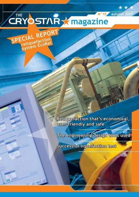
N°10<br />
autumn 2007<br />
SPECIAL REPORT<br />
reliquefaction<br />
system EcoRel<br />
Reliquefaction that’s economical,<br />
user-friendly and safe<br />
<strong>The</strong> engineering design tools used<br />
Successful liquefaction test
EDITO<br />
This issue of the CRYOSTAR <strong>Magazine</strong> is entirely dedicated to the first EcoRel on-board<br />
LNG re-liquefaction units produced by <strong>Cryostar</strong>.<br />
You will learn about the technology involved, the tools, means and infrastructure which<br />
were implemented, the testing of the units and the position of <strong>Cryostar</strong> in the LNG ship<br />
market.<br />
<strong>The</strong> project of delivering 14 such units within 24 months is one of the main challenges<br />
<strong>Cryostar</strong> has ever faced. It is an example of the values we advocate in our company, namely<br />
taking up challenges, being innovative, and being passionate about what we do. Our people,<br />
in all departments, have worked intensively on this project with great enthusiasm. It was not<br />
plain sailing, but overall we were very pleased with the achievements.<br />
<strong>The</strong> production of the EcoRel units is also a step forward in <strong>Cryostar</strong>’s core competencies.<br />
From a pure supplier of rotating machines, we have evolved into a supplier of process solutions<br />
around natural gas liquefaction and distribution and clean energy applications. To<br />
achieve this change we have hired process engineers, project managers, sales engineers, test<br />
engineers, and service engineers. Now we employ more than 400 highly qualified people who<br />
are all supportive of our strategy and our company objectives.<br />
What will be <strong>Cryostar</strong>’s next challenge? It won’t be long before you’ll be reading about it in<br />
one of our next issues!<br />
Daniel MEYER<br />
President<br />
How it works ............. p 3<br />
How we tested it ............. p 6<br />
How we developed it ............. p 8<br />
<strong>Cryostar</strong> and the LNG carrier market ............. p 10<br />
Infrastructure needed ............. p 11<br />
Events ............. p 11<br />
2<br />
Autumn 2007
HOW IT WORKS<br />
EcoRel, how it works<br />
Thanks to its low power consumption, the <strong>Cryostar</strong> EcoRel Boil Off Gas (BOG)<br />
re-liquefaction system has been selected to equip the largest ever built Q-Max series<br />
LNG carriers (14 vessels on order already).<br />
<strong>The</strong> concept of EcoRel is to be economical but also user-friendly and safe for the<br />
environment.<br />
It performs full re-liquefaction of the BOG. <strong>Cryostar</strong> has designed the process as well<br />
as the machines. This guarantees the best possible match between the process and the<br />
rotating equipment.<br />
History of LNG carrier propulsion<br />
Natural gas is transported over long distances<br />
in liquid form, at ambient atmospheric pressure,<br />
near its boiling point (-163°C) in insulated tanks<br />
onboard LNG carriers. Due to unavoidable heat<br />
inleak during the voyage, a portion of the cargo<br />
vaporizes, equivalent to about 3 % of the total<br />
volume over 20 days. In order to maintain the<br />
tank pressure close to atmospheric pressure the<br />
vapor generated by this vaporization must be<br />
removed from the tank.<br />
Historically, so as not to waste it, the BOG was<br />
burned in boilers to produce steam for the ship’s<br />
propulsion. Until very recently all LNG carriers<br />
relied on steam turbines for their propulsion and<br />
are the last vessels built with this type of propulsion.<br />
However, in recent times, the evolution<br />
of fuel costs, and the lack of crew with steam<br />
propulsion experience, has promoted innovation<br />
in the conservative LNG carrier world.<br />
Two new propulsion systems are now being<br />
implemented in addition to steam turbine<br />
propulsion. Other propulsion systems, like gas<br />
turbine or 250 bar gas injection, are still under<br />
investigation.<br />
One of the two new concepts was the Dual Fuel<br />
Diesel Electric (DFDE) system. It burns the BOG<br />
(at ~ 6 bar) in dual fuel diesel engines (gas or<br />
diesel oil). <strong>The</strong>se engines drive generators to<br />
produce electricity for the electric motors driving<br />
the ship. <strong>Cryostar</strong> collaborated actively with<br />
shipbuilders in the development of the gas handling<br />
system for these vessels and has supplied<br />
the compressors for all delivered DFDE LNG<br />
carriers.<br />
<strong>The</strong> other concept, subject of this article, completely<br />
splits cargo handling from the propulsion<br />
of the vessel. It maintains the cargo pressure and<br />
inventory by re-liquefying the BOG generated<br />
in the tanks and relies on cheaper heavy fuel oil<br />
(HFO) for the ship’s propulsion using slow speed<br />
diesel engines.<br />
Following an intensive 15-month testing process<br />
by Exxon-Mobil, the <strong>Cryostar</strong> re-liquefaction<br />
system EcoRel has been selected for the largest<br />
ever built Q-Max series LNG carriers. <strong>The</strong> capacity<br />
of these vessels, 265 000 m3, exceeds by<br />
far all that of all other LNG vessels ever built.<br />
Autumn 2007 3
HOW IT WORKS<br />
General considerations<br />
<strong>The</strong> installation of a re-liquefaction system onboard<br />
a vessel is subject to spatial and operational constraints<br />
that do not exist in on-shore plants.<br />
On shore re-liquefaction systems operate most of<br />
the time at constant load and almost continuously.<br />
On the vessel the volume of BOG varies quite a lot<br />
(laden voyage versus ballast voyage, sea conditions,<br />
tank spraying, etc.) and operation is not continuous<br />
since no re-liquefaction takes place during the loading<br />
or unloading of the tanks. <strong>The</strong> re-liquefaction<br />
process is thus stopped and restarted every 2 to 3<br />
weeks depending on the route of the vessel.<br />
To cope with these constraints <strong>Cryostar</strong> targeted<br />
low power consumption but also a simple, sturdy<br />
and easy to operate system allowing the process to<br />
be started quickly.<br />
<strong>Cryostar</strong>’s EcoRel concept is environmentally<br />
friendly. It performs full re-liquefaction of the BOG<br />
whereas other systems perform partial re-liquefaction<br />
and have to enrich the vented gas with methane in<br />
order to get a correct combustion before releasing it<br />
to the atmosphere.<br />
Additionally, with the full reliquefaction no nitrogen<br />
depletion takes place during the voyage so that nitrogen<br />
does not need to be added in the re-gasification<br />
terminal in order to maintain the gas heating value.<br />
In fact LNG is a mixture of gases, methane being<br />
the main component. It also contains, in addition to<br />
butane, propane and ethane, up to 1% of nitrogen,<br />
depending on the loading terminal. <strong>The</strong> boiling<br />
point of nitrogen, under ambient conditions is<br />
-196°C, which is well below the -163°C temperature<br />
in the tank. This explains the high concentration of<br />
BOG<br />
Desuperheater<br />
BOG<br />
Condenser<br />
N2 Counter<br />
Current Exchanger<br />
N2 Compander<br />
N 2<br />
LOOP<br />
N2 inter<br />
& after coolers<br />
nitrogen in the boil off gas: up to 30% compared to<br />
around 1% nitrogen in the LNG. (Almost no heavy<br />
hydrocarbons are present in the BOG since their<br />
boiling point temperatures are much higher than the<br />
LNG temperature).<br />
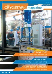
Principle<br />
<strong>The</strong> EcoRel re-liquefaction system relies on the<br />
principle of a closed nitrogen reverse Brayton cycle<br />
to produce the cold power needed to condense the<br />
BOG. <strong>The</strong> amount of cold production is proportional<br />
to the amount of boil off gas to be re-liquefied<br />
and is adapted by modifying the mass circulating in<br />
the nitrogen loop. <strong>The</strong> condensation temperature is<br />
a function of the boil off gas composition and of the<br />
selected pressure at which the condensation takes<br />
place.<br />
<strong>The</strong> cycle includes 3 warm compression stages with<br />
intercoolers and after-coolers and one cryogenic expansion<br />
turbine combined in a single machine called<br />
a “compander”, a machine developed by <strong>Cryostar</strong><br />
in 1996.<br />
<strong>The</strong> cycle also includes a counter current heat<br />
exchanger and the condensing part in which the<br />
cold power is exchanged with the BOG. Operating<br />
flexibility determined the choice of splitting the<br />
condensing part into two elements: a de-superheater<br />
and a condenser. This arrangement allows the BOG<br />
loop to be started quickly, and process flexibility for<br />
different BOG compositions.<br />
<strong>The</strong> BOG side consists of a two-stage compressor<br />
with inter-cooler, which relays the gas to the desuperheater<br />
and the condenser and then the return<br />
of the sub-cooled condensate to the tank.<br />
Data<br />
<strong>The</strong> quantity BOG needing to be re-liquefied on a<br />
Q-Max vessel is ~ 7 T/h. It requires a compander<br />
power of ~ 5.2 MW assuming -100°C gas inlet temperature<br />
at the BOG compressor inlet.<br />
Control<br />
<strong>Cryostar</strong> provides the process controls as well as<br />
the machine’s control logic for full integration in<br />
the LNG carrier’s central Integrated Automation<br />
System IAS. <strong>The</strong> process and the associated control<br />
4<br />
Autumn 2007
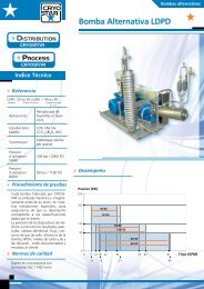
HOW IT WORKS<br />
concept of the complete<br />
system have been developed<br />
with the help<br />
of static and dynamic<br />
simulation tools and<br />
have been validated by<br />
nitrogen liquefaction<br />
tests. <strong>The</strong> <strong>Cryostar</strong> deep<br />
knowledge of the design<br />
but also under off design<br />
conditions allows <strong>Cryostar</strong><br />
to generate good<br />
an accurate machines<br />
models.<br />
BOG<br />
Intercooler<br />
BOG LOOP<br />
BOG<br />
Compressor<br />
BOG<br />
Desuperheater<br />
BOG<br />
Condenser<br />
N2 Counter<br />
Current Exchanger<br />
N2 Compander<br />
N2<br />
Cold BOG<br />
Warm BOG<br />
Condensate<br />
N 2<br />
LOOP<br />
N2 inter<br />
& after coolers<br />
Machine<br />
<strong>The</strong> two-stage BOG<br />
compressors are fieldproven.<br />
In fact, they are similar to the ones installed<br />
on DFDE vessels except that their discharge pressure<br />
is lower for the re-liquefaction system.<br />
<strong>The</strong> compander technology (3 warm compressor<br />
stages and one cryogenic turbine stage on a common<br />
single gearbox) has been proven since 1996 when<br />
<strong>Cryostar</strong> first implemented this integrated machine<br />
concept in air separation plants.<br />
<strong>The</strong> motor is driven by a 6MW variable frequency<br />
drive in order to limit the inrush current. <strong>The</strong> ship,<br />
with very limited power generating capacities, operates<br />
in an island mode. <strong>The</strong> start up, which has a big<br />
energy consumption, is challenging each time.<br />
TANK 5 TANK 4 TANK 3 TANK 2 TANK 1<br />
electrical blackout on a vessel than in on-shore plants<br />
require a flexible and simple system.<br />
<strong>Cryostar</strong> has reached a very good compromise with<br />
the EcoRel solution: quite low power consumption<br />
levels and a sturdy easy-to-operate system.<br />
This concept could of course also be used for small<br />
on-shore projects. It can obviously be adapted depending<br />
on related operating constraints. For plants<br />
operating continuously additional features could also<br />
be implemented to reduce the operating costs.<br />
<strong>Cryostar</strong> has developed and patented different concepts<br />
for the re-liquefaction of boil off gases.<br />
Low capital costs, as well as the lowest possible<br />
power consumption<br />
(in order to keep<br />
the operating costs as low as<br />
possible), are of course a common<br />
generic target for<br />
all re-liquefaction<br />
systems; but operational<br />
flexibility is also<br />
essential on a vessel. <strong>The</strong> different<br />
modes of operation, the different LNG and thus<br />
BOG compositions and the higher likelihood of an<br />
Autumn 2007 5
HOW WE TESTED IT<br />
How we tested EcoRel<br />
<strong>Cryostar</strong>’s quality control rules mean that all manufactured<br />
turbines, compressors or pumps have to be<br />
tested before delivery. This also applies to the rotating<br />
equipment for the “EcoRel”, (Economic ecologic<br />
reliable boil-off gas Reliquefaction) system installed<br />
on LNG carriers. However the recurrent testing of a<br />
6MW Compander (three combined compressor stages<br />
and one cryogenic expansion turbine on one common<br />
gearbox) required special considerations.<br />
In addition to testing the machines, <strong>Cryostar</strong> also<br />
validated the reliquefaction process by liquefying<br />
nitrogen in a mockup installation.<br />
One of the challenges that needed to be addressed to<br />
test the machinery was the electrical supply. A ship’s<br />
electrical frequency is 60 Hz whereas the European<br />
grid frequency is 50 Hz. <strong>Cryostar</strong> had already the<br />
capability to drive motors up to 1.8 MW and 6000V<br />
at 60 Hz, but to drive the 6 MW 3300V compander<br />
motor, <strong>Cryostar</strong> had to invest in a 7.2 MVA variable<br />
frequency drive. Due to local power grid limitations,<br />
<strong>Cryostar</strong> also had to rent two 1 MW gensets for type<br />
testing of one unit at full power in order to demonstrate<br />
the mechanical integrity of the machine. <strong>The</strong><br />
recurrent testing power for all following units was be<br />
limited to 4 MW.<br />
All companders are tested with a dedicated oil system<br />
and inter-stage piping together with intercoolers<br />
and an after-cooler. Special piping and a special test<br />
procedure have been developed in order to combine<br />
the performance and mechanical running tests,<br />
performed within a closed loop filled with dry air.<br />
<strong>The</strong> resulting test conditions are close to nominal<br />
operating conditions onboard the vessel for the three<br />
compression stages.<br />
This test allows the verification of the aerodynamic<br />
performance of all stages, the checking of the mechanical<br />
integrity of the machine under load and<br />
the confirmation that the anti surge system works<br />
as well as assuring the good functioning of all the<br />
instruments, and associated systems (gas seals, lube<br />
oil, etc...).<br />
Such high load testing required high investment for<br />
the needed infrastructure and important resources<br />
for the recurrent complete unit assembly and installation,<br />
and also has a high power consumption.<br />
6<br />
Autumn 2007
HOW WE TESTED IT<br />
<strong>Cryostar</strong> thinks that it was worth it, so<br />
that once installed on site the delivered<br />
machines are just perfect.<br />
To validate the reliquefaction concept,<br />
<strong>Cryostar</strong> has built a full-scale mockup<br />
installation able to liquefy nitrogen using<br />
the equipment. <strong>The</strong> purpose of this test<br />
was to demonstrate that the equipment<br />
and associated control concept worked<br />
according to expectations. Since boil-off<br />
gas was not available, the system was<br />
tested with nitrogen.<br />
<strong>The</strong> nitrogen loop, which is the cooling<br />
loop of the reliquefaction system, was<br />
identical to the one installed on a vessel<br />
from a functional point of view. <strong>The</strong> piping layout<br />
was adapted to the mockup installation. For the boiloff<br />
gas side, some modifications were made in order<br />
to represent the ship’s operation. <strong>The</strong> core part of the<br />
system was kept similar to a ship’s process and full<br />
equipment was used, i.e.: condenser, de-superheater,<br />
flash drum, and pump.<br />
<strong>The</strong> liquefaction of nitrogen is more demanding than<br />
the liquefaction of LNG boil-off gas. It requires a<br />
lower temperature (as low as -183°C depending on<br />
pressure). This leads to a very cold temperature close<br />
to that needed for liquid formation at the turbine<br />
outlet, as we have to liquefy N2 with gaseous N2.<br />
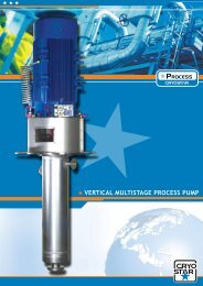
Simplified Process Flow Diagram<br />
N2 liquefaction test<br />
N2<br />
vaporizer<br />
LNG return pump<br />
10.P.01<br />
LN2 supply<br />
BOG<br />
Condenser<br />
10.E.01<br />
LNG flash<br />
drum<br />
10.V.01<br />
BOG<br />
Desuperheater<br />
10.E.03<br />
N2 Counter<br />
Current<br />
Exchanger<br />
20.E.01<br />
N2 Compander<br />
21 & 22.C.01<br />
N2 supply<br />
N2 Drum<br />
20.V.01<br />
N2 inter<br />
& after coolers<br />
21 & 22.E.01~03<br />
N2<br />
N2 to liquefy<br />
Liquid N2<br />
<strong>The</strong> test was conducted in different steps in order<br />
to validate the sequences (start/stop/ESD), to tune<br />
the controllers and finally to confirm that the overall<br />
concept was sound.<br />
After tuning the control loops, the installation<br />
worked well, and we were able to liquefy the expected<br />
flow of N2 with the expected power consumption.<br />
<strong>The</strong> testing was performed in summer 2007 and<br />
successfully witnessed by ship builder’s and end user<br />
representatives on August 16th.<br />
<strong>Cryostar</strong> does not compromise in the testing of its<br />
equipment even if it requires heavy investment –<br />
product quality always comes first.<br />
Autumn 2007 7
HOW WE DEVELOPED IT<br />
EcoRel, how we developed it<br />
When <strong>Cryostar</strong> first obtained the order for the ‘design, procurement and construction of on-board re-liquefaction<br />
plants’ the project team knew that it had to rely on first class tools in order to get the job done. This article<br />
examines three examples of such engineering design tools, explains the context in which they were used and shows<br />
how they contributed to the successful completion of the EcoRel project.<br />
INDISS <br />
For the EcoRel project <strong>Cryostar</strong> was responsible for<br />
both rotating machinery performance and also for<br />
the performance of an entire plant. In order to build<br />
the on-board re-liquefaction plant it was necessary<br />
to master the process of the plant. For this purpose<br />
<strong>Cryostar</strong> used a high fidelity dynamic simulation platform<br />
provided by RSI Simcon (part of the IFP group)<br />
that was used in conjunction with the static process<br />
simulation tool HYSYS. <strong>The</strong> dynamic simulation tool<br />
called INDISS is designed in multi-layer component<br />
architecture. <strong>The</strong> open environment allowed <strong>Cryostar</strong>’s<br />
engineers to implement their own proprietary<br />
components of the on-board re-liquefaction plant.<br />
Expanders, compressors, anti-surge protection and<br />
load sharing heat-exchangers and N2 make-up systems<br />
were all coded in the dynamic plant model.<br />
<strong>The</strong> performance characteristics of the rotating machinery<br />
components of the plant were cross-checked<br />
and adjusted during the open loop performance test<br />
that was conducted at the <strong>Cryostar</strong> test facility.<br />
<strong>The</strong> comparison with the test results allowed<br />
an adjustment of the parameters of the plant<br />
model which were previously based on predictions.<br />
During the full N2 loop test the plant<br />
model showed excellent comparisons<br />
with the measurements at the test bench and provided<br />
a useful learning tool for the operation of the plant.<br />
CAESAR II<br />
Another tool essential to the design of the EcoRel project<br />
proved to be CAESAR II (by COADE Engineering<br />
Software) a pipe stress analysis tool. <strong>The</strong> tool allowed<br />
a quick generation of the 3D model of the related piping<br />
for the on-board re-liquefaction plant based on a<br />
piping list, isometrics and the P&ID. A comprehensive<br />
material database with allowable stresses helped the<br />
user enter the piping material characteristics of the<br />
piping layout (ex: a variety of loads had to be applied<br />
to the model). Factors such as weight (including the<br />
thermal insulation), pressure and temperature gradients<br />
and shipboard accelerations as specified by the<br />
ship builders all had to be taken into account. Every<br />
element of the design was entered with the detailed<br />
supplier information.<br />
CAESAR II was then used to assess the loads on the<br />
rotating machinery, the aluminium plate fin heat exchangers<br />
and the shell and tube heat exchangers of the<br />
on-board re-liquefaction plant. Displacements at each<br />
flange were calculated to check the support dimensions<br />
and to verify potential interference with the piping. 3D<br />
graphics enabled a quick and efficient review of the<br />
results.<br />
8<br />
Autumn 2007
HOW WE DEVELOPED IT<br />
CFD<br />
A third tool used for the EcoRel<br />
project was a Computational Fluid<br />
Dynamics code (CFD). <strong>The</strong> code<br />
from NUMECA allows the flow<br />
inside the rotating and stationary<br />
blade passage to be modelled<br />
based on a finite volume numerical<br />
method. For every calculation of a<br />
given passage inside the machine<br />
a structural mesh was generated<br />
with Autogrid and the 3D<br />
Navier-Stokes equations were<br />
computed with Fine/Turbo assuming<br />
smooth walls and adiabatic<br />
expansion or compression. Closure<br />
of the equations was given by the<br />
Spalart-Allmaras turbulence model.<br />
For the EcoRel project different<br />
flow features of the N2 compander<br />
were computed and the results were<br />
analysed using a 3D viewer.<br />
A first CFD study concerned the static pressure field<br />
inside the nozzle blades of the expander stage. This<br />
computation allowed an estimation of the torque<br />
on the nozzle blades and helped to verify that the<br />
nozzle actuator was correctly sized for design and<br />
off-design duty.<br />
A second CFD study examined the flow in the interconnecting<br />
piping between the compressor stages.<br />
Stringent space constraints on-board ship resulted<br />
in having to optimise the aerodynamic performance<br />
of interconnecting piping with a small footprint.<br />
CFD helped to position flow straighteners inside the<br />
interconnecting piping in order to find the best compromise<br />
between the available space and the requirement<br />
of an undistorted flow field at the compressor<br />
inlet.<br />
Further CFD studies analysed the performance<br />
impact of different compressor hub noses, different<br />
compressor diffuser geometries and the impact on<br />
efficiency of the tip clearance height. In addition<br />
to the design flow case off-design cases (low flow,<br />
high flow) were also studied. Finally the results were<br />
compared with test bench measurements.<br />
<strong>The</strong> design of EcoRel in the given lead-time of the<br />
project would have been unthinkable without the<br />
extensive use of state of the art computer tools.<br />
<strong>Cryostar</strong> clearly gives itself the means to achieve its<br />
goals.<br />
Autumn 2007 9
LNG<br />
<strong>Cryostar</strong> and the LNG carrier market<br />
<strong>Cryostar</strong> is the only supplier for the combined cryogenic machinery on board LNG carriers, selling the<br />
compressors as an integrated package with the cargo handling heat exchangers. <strong>Cryostar</strong>’s unique know-how<br />
in this sector results in ship builders consulting <strong>Cryostar</strong> regarding proper sizing, interfacing and utilisation of<br />
the equipment.<br />
A solution for all types of ship propulsion systems.<br />
Until only a few years ago, machineries on LNG tankers were based on single steam turbine technology where<br />
the required steam was produced by two dual-fuel boilers, which use both boil-off gas and heavy fuel oil.<br />
As environmental issues are becoming more and more important, ship builders and owners have started to look<br />
for alternative propulsion systems to move away from the less efficient steam turbine technology.<br />
Consequently, and to anticipate the technological evolution, <strong>Cryostar</strong> has developed a combination of solutions<br />
applicable to any of the propulsion systems chosen for the future.<br />
Irrespective of the selected ship drive system (conventional steam turbine, dual fuel engine, diesel electric drive<br />
system, gas turbine or diesel engine with liquefaction plant), <strong>Cryostar</strong> has the right combination of products for<br />
assuring reliable ship operation.<br />
<strong>Cryostar</strong> is the only supplier for the combined cryogenic machinery for the cargo handling systems on LNG<br />
carriers with:<br />
1. Boil-off Gas Compressors – used to keep the LNG tanks on board ship at the right temperature and pressure.<br />
2. Gas heaters and vaporizers – used to warm up the boil-off gas which is then used to power the ship.<br />
3. the re-liquefaction concept, EcoRel, combining a cooling plant and various components used in air separation<br />
and nitrogen liquefying plants (see main article).<br />
Over the last few years, <strong>Cryostar</strong> has developed strong commercial and technical relationships with all major<br />
ship builders in China, Korea and Japan, but also in Europe. Orders were received from almost all major ship<br />
builders in the world, namely Daewoo, Samsung, Hyundai, Mitsui, Mitsubishi, Kawasaki, Universal, Hudong-<br />
Zhonghua, Chantiers de l’Atlantique (now Aker), Fincantieri and IZAR.<br />
A large installed base and order book<br />
As of today out of 237 ships in operation, there are <strong>Cryostar</strong> compressors and <strong>Cryostar</strong> heat exchangers on 196<br />
ships. In addition, <strong>Cryostar</strong> has machines on order to equip 53 under construction. To which we need to add the<br />
14 Ecorel re-liquefaction units for the Q-max<br />
ships presently on order.<br />
As shown above, <strong>Cryostar</strong> has developed itself<br />
a strong position since the mid 70s. From being<br />
originally a supplier of machinery for industrial<br />
gas applications, the company has transformed<br />
into a more diversified organisation supplying<br />
other markets. Today, the LNG ship market is<br />
<strong>Cryostar</strong>’s main business segment!<br />
10<br />
Autumn 2007
INFRASTRUCTURE NEEDED<br />
Infrastructure needed<br />
for EcoRel production<br />
Lots of additional resources were needed to support the challenge of designing,<br />
producing, assembling, testing, and shipping the EcoRel units.<br />
First, a new 1200 m2 assembly hall was completed in February 2006<br />
(see Spring 2006 edition) equipped with two 50-tonne cranes and eight<br />
one-tonne jib cranes. <strong>The</strong> total investment for this additional production<br />
structure was € 2.5 million.<br />
Adjacent to this new workshop, a fully equipped new test facility was<br />
completed in Spring 2007. It is dedicated to the re-liquefaction units as<br />
well as large hydrocarbon turbines. <strong>The</strong> main characteristics of this test<br />
building are:<br />
● 650 m2 total test surface<br />
● One 50-tonne bridge crane<br />
● Two one-tonne jib cranes<br />
● Two surface plates for machine testing<br />
● 8 MW power supply<br />
● Compressed air supply of 20,000 m3/h at 10 bar<br />
● Cooling water circuit 550 m3/h with 6 MW cooling tower<br />
● 6 MW variable frequency drive<br />
<strong>The</strong> total investment was € 3.5 million<br />
<strong>The</strong> test facility also includes a compressor room, an electric room, a<br />
computerized test commando room and a small conference room – in<br />
total some additional 300 m2.<br />
Events<br />
November 13-16, 2007<br />
Cryogen-Expo 2007, All-Russian Exhibition<br />
Center, hall No 70 “Moskva”, Moscow, Russia.<br />
November 27-29, 2007<br />
ANGVA 2007 (the Biennial Conference and Exhibition<br />
of the Asia-Pacific Natural Gas Vehicles<br />
Association), BITEC, Bangkok, Thailand.<br />
More info : www.angvaevents.com<br />
February 20-22, 2008<br />
Clean Heavy Duty Vehicle Conference, Hilton San<br />
Diego Resort, San Diego, California.<br />
More info : www.cleanheavyduty.org<br />
March 14-16, 2008<br />
FUELLING PAKISTAN 2008 (International<br />
Exhibition on CNG, LPG &<br />
Alternative Sources of Energy), Fortress<br />
Stadium Lahore, Lahore, Pakistan.<br />
February, 2008<br />
AIIGMA (All India Industrial Gases Manufacturers’<br />
Association), New Delhi, India<br />
March 10-13, 2008<br />
23rd GASTECH, Bangkok International Trade<br />
& Exhibition Centre, Bangkok, India.<br />
More info : www.gastech.co.uk<br />
Autumn 2007 11
© <strong>Cryostar</strong> - all rights reserved<br />
Contact: magazine@cryostar.com<br />
www.cryostar.com