
Create successful ePaper yourself
Turn your PDF publications into a flip-book with our unique Google optimized e-Paper software.
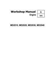
Publ . n r 7730974-84-1990WORKSHOP MANUALVOLVOPENTA
FOREWORDThis workshop manual contains repair instructions for the 2001, <strong>2002</strong> and 2003 engines.The instructions concerning overhauling describe the most suitable working method using the special tools listed underthe heading "Special tools" .Both the engine designation and its serial number must be clearly stated in all correspondence concerning the engine andwhen ordering parts .We reserve the right to carry out design modifications and, for this reason, the contents of this manual cannot be regarded asbinding .AB VOLVO PENTATechnical Publications DepartmentSI UNIT SYSTEMUnits according to the international SI system have been used in this book . The earlier units are given after the SI units .Power is given in kW (kilowatt) Speed is given in rev/s (revolutions per second)earlier unit hp (horse-power)earlier unit rev/min (revolutions per minute)Torque is given in Nm (newton metre) Volume is given in dm3 (cubic decimetre)earlier unit kpm (kilopond metre)earlier unit l (litre)earlier unit lbf ft (poundfoot) earlier unit Imp. gal (Imperial gallon)earlier unit US gal (United States gallon)Pressure is given in Pa (Pascal)earlier unit kp/cm2 (kiloponds per square centimetre)earlier unit Ibf/in 2 (pounds per square inch)
INDEXComponents guide . . . . . . . . . . . . . . . . . . . . . . . . . . . . . . . . . . 2DISASSEMBLY. . . . . . . . . . . .. . . . . . . . . . .. . . . . . . .. . . . . . . . . . . .. . . . . . . . .. . . . . . . . . . . . .Cylinder head . . . . . . . . . . . . . . . . . . . . . . . . . . . 3Transmission . . . . . . . . . . . . . . . . . . . . . . . . . . . . 4Piston, piston rods . . . . . . . . . . . . . . . . . . . . . . . . . . 5Flywheel . . . . . . . . . . . . . . . . . . . . . . . . . . . . . . . . 5Crankshaft . . . . . . . . . . . . . . . . . . . . . . . . . . . . . . . . . 5Camshaft . . . . . . . . . . . . . . . . . . . . . . . . . . . . . . 5OVERHAUL. . . . .. . . . . . . . . . .. . . . . . . . .. . . . . . . . . . . . . .. . . . . . . . . . . .. . . . . . . . .. . . . . . . . . . . . .. . . . . . . . . . . . . . .. . . . .. . . . . . .. . . . . . . . . . . .. . . . . . . . . .. . . . . . . . . . . . . . . .. . . . . .. . . . . . . .. . . . . . . .Disassembling the cylinder head . . . . . . . . . . . . . . . . 7Valve guides . . . . . . . . . . . . . . . . . . . . . . . . . . . . . 7Valve seats . . . . . . . . . . . . . . . . . . . . . . . . . . . . . . . . 7Valves . . . . . . . . . . . . . . . . . . . . . . . . . . . . . . . . 7Valve springs . . . . . . . . . . . . . . . . . . . . . . . . . . . 8Rocker arm mechanism . . . . . . . . . . . . . . . . . . . . 8Injector sleeve . . . . . . . . . . . . . . . . . . . . . . . . . 8Injectors . . . . . . . . . . . . . . . . . . . . . . . . . . . . . 8Assembling the cylinder head . . . . . . . . . . . . . . . . . . . 9Feed-pump . . . . . . . . . . . . . . . . . . . . . . . . . . . . . . . . . 10Pistons . . . . . . . . . . . . . . . . . . . . . . . . . . . . . . . . 11Crankshaft . . . . . . . . . . . . . . . . . . . . . . . . . . . . . . . 11Camshaft . . . . . . . . . . . . . . . . . . . . . . . . . . 11Connecting rods . . . . . . . . . . . . . . . . . . . . . . . . . . . . .12Thermostat . . . . . . . . . . . . . . . . . . . . . . . . . . . . . . . . 13Sea-water pump . . . . . . . . . . . . . . . . . . . . . . . . . . . 13ASSEMBLY. . . . . . . . . .. . . . . . . . . . .. . . . . . . . . . .. . . . . . . . . . .. . . . .. . . .. . . .... . .. .Crankshaft . . . . . . . . . . . . . . . . . . . . . . . . . . . . . . . 14Pistons . . . . . . . . . . . . . . . . . . . . . . . . . . . . . . . . . 14Flywheel . . . . . . . . . . . . . . . . . . . : . . . . . . . . . . . . 15Transmission . . . . . . . . . . . . . . . . . . . . . . . . . . . 15Adjusting the valve clearance . . . . . . . . . . . . . . . . . . 17Checking the injection angle . . . . . . . . . . . . . . . . . . . . 172003 Turbo . . . . . . . . . . . . . . . . . . . . . . . . . . . . . . . . . . . . 21Fresh water cooling . . . . . . . . . . . . . . . . . . . . . . . . . . . . . . . 25Electrical system . . . . . . . . . . . . . . . . . . . . . . . . . . . . . . . . . . . 26Fault tracing scheme . . . . . . . . . . . . . . . . . . . . . . . . . . . . . . 28Special tools . . . . . . . . . . . . . . . . . . . . . . . . . . . . . . . . . . . . 29Technical Data . . . . . . . . . . . . . . . . . . . . . . . . . . . . . . . . . . . 30
COMPONENTS GUIDE81 . Exhaust elbow2 . Injectors3. Temperature sender4 . Electrical distribution box5 . Fuel filter6 . Alternator7 . Starter motor8 . Drainage, cooling water9 . Feed-pump10 . Engine serial number11 . Decompression device12 . Inlet air silencer13. Fuel injection pumps14 . Oil dipstick15 . Sea-water pump
injectionRemoveNOTE! The cylinderaremust notbe cleaned withDISASSEMBLYDrain off the cooling water and the lubricating oil from theon engine cradle p/n 9992520 and fixture p/n 884837 . If theengine is fresh water cooled, see page 21 .3 . Remove the fuel filter, the oil filter, the feed-pump, thethermostat housing and the exhaust elbow . Also removethe sea-water pump with its attachment tubes .1 . Remove the alternator, the tensioner bracket and thestarter motor . Remove the connections from the electricaldistribution box from the engine and remove the box andthe wire harness .2 . Remove the return fuel line, the fuel pressure lines andthe inlet air silencer . Install protection caps on the fuelpumps and injectors . Remove the screw holdingthe lever of the decompression device (1) and pull out thelever . Remove the valve cover .4 . Remove the valve bridge and lift out the push rods .the rubber rings fortheoil pipe . Remove the cylinderhead and the valve lifters . Put the lifters on a rack inconsecutive order, head bolts phosphatised andasteelbrush .
liftersbracingremove5 . Remove the fuel injection pumps . Mark the pumps toensure installation in the same cylinders from which theywere removed . Take care of the shims . Remove the screwson the side of the engine block and lift out the pump.7 . Remove the transmission cover : Start by removing thethrottle control cover . Use a suitable type of pliers tothe spring (1) . Then remove the end-nipple (2) andthe spring (3) . Remove the oil pump cover and mark thegear wheels with a colour-pen before removing them .(When installing the gear wheels, the marked side must befacing outwards) . Remove the bracing pin of the camshaftusing the special tool 884839 . Never remove thepin by punching p/n it out, this can very well bend thecamshaft . Remove the screws on the transmission coverand pull it straight outwards .8 . The max .-volume-screw (1) and the max .-rev-screw (2)are set by Volvo Penta and must never be changed sincethis will affect the engine output .6. Remove the pulley center bolt and pull off the pulleyusing puller p/n 9992265 . Place a protection pad betweenthe puller and the crankshaft to avoid the crankshaft beingdamaged .9 . Remove the control rod . Start by removing the plug atthe rearof the block and thetwo screws on the pump plane,holding the control rod .
connecting10 . Pull out the camshaft .12 . Turn the engine upside down and remove the oil pan .Be careful as the pan is glued . NOTE! The oil pan ends alsofunction as main bearings .11 . Remove the outer flywheel housing, the flywheel andthe inner flywheel housing .13 . Remove the connecting rod bolts and remove therods and the pistons . The connecting rod and theconnecting rod cap are marked with figures .
punched14 . Remove the main bearing caps . The main bearing capsare marked with a figure . The corresponding figure isinto the block . Lift out the crankshaft . On later engineversions an arrow is cast in the separate main bearing caps(<strong>2002</strong>, 2003) . The arrow is to point towards the dipstick.
necessaryturbocharged3 . Use mandrel p/n 5218 to press out the valve guides . Oilthe new valve guides externally and use mandrel p/n884559 to install them . Press down the mandrel all the waydown to the cylinder head . Ream the valve guides if.THE CYLINDER HEAD1 . Remove the "collets" and valve springs using a valvebow . Remove the valves . Remove the valve stem seals .Place the valves in the proper sequence in a valvestand .Valve guides2 . Check the valve guide wear by inserting anew valve steminto the guide. Measure the play using a dial indicator . Ifnecessary, replace the valve guides .Wear limits :Inlet valve, max play . . . . . . . . . . . . . . . 0 .15 mm (0.0059 in)Exhaust valve, max play . . . . . . . . . . . . 0 .15 mm (0.0059 in)Valve seats and valves4 . Mill or ream the valve seats . The angle (C) should be 45°(for 2003T, 30° for the inlet valve). The sealing surface's width(B) should be 1 ±0 .1 mm (0.039±0.0039 in) . Grind the valvesin a valve grinding machine . The angle (D), see Tech . data . Ifthe disc thickness after grinding is less than 1 .0 mm (0 .039 in)for naturally aspirated engines or 0 .8 mmin) forengines, the valves must be scrapped (0.031.Valves withbent stems, or if the measurement (A) exceeds 2 .5 mm (0.098in) must also be scrapped . Grind the valve tip towards therockers if necessary . Lap in the valves using valve grindingpaste and check the contact area with marking dye .
ottomshittingathinneror athicker one dependingReplacing the valve seat exhaust port 2003TGrind down the valve disc of a discarded valve to just below27 mm (1 .063 in) diameter . Push the valve stem through theguide . NOTE! Do not push in too far- the valve disc should bejust below the edge of the seat . Spot weld the disc in place atthree points using a electric welder . Knockout the seat bythe valve guide with a plastic-headed hammer .Cool the new seat to approx . -20°C (-4°F); the cylinderhead should beat room temperature (+ 20°0168°F) . Place thecooled seat on tool 884961-4 and knock it downtowardsuntil it. NOTE! Turn the seat with the valve facethetool .Rocker arm mechanism6 . Disassemble the rocker arm mechanism and clean theparts . Check the wear of the shaft and rockerarm bushings.Should the bushings need to be replaced, usethe mandrelp/n 9991867 for the removal and installation, (make surethat the oil hole in the bushing coincides with the one in therocker arm) . After the installation the bushings are reamedto a close running fit. When installing the rockerarm shaft,it must be turned so that the lubrication holes are facing thevalve-side . Check to make sure that the rocker arm contactsurface againstthe valve is concave. Minor adjustments aremade in a valve grinding machine . Oil the shaft and installthe parts .Valve springs5 . Checkthe free length ofthe valve springs and the lengthwhen loaded .L = Length, unloaded 42,5 mm (1 .67323 in .)L1 = Length, loaded with 170±10 N (17±1 kp) 32 mm(1 .25984 in .)L 2 = Length, loaded with 300±20 N (30±3 kp) 24 mm(0.94488 in .)Pressure testing the nozzles7 . Check the nozzle's spray pattern at the correct openingpressure (see Technical Data) . Check also that the fuel spraysstop simultaneously and no dripping occurs .Adjust the opening-pressure with adjustment-washers (1)being available in different thicknesses from 1 mm U3937in .) to 1,95 mm ( .076772 in .) in steps of 0,05 mm ( .001969in .) . Disassemble the injector and replace the adjustment-washer againstwhether the pressure must be reduced or increased .Assemble the injector and check the opening-pressure andthe spray-pattern .
orderflaringInjector-sleeve8 . Insert the expanding screw on the special tool p/n 10 . Oil theflare-tool p/n 884283 and insert it intothe sleeve884811 into the copper sleeve and turn the screw(make sure that the dowel is properly retracted) . Brace theanti-clockwise untilthescrewhastuckinthe sleeve . Tighten tool with the injector yoke . Screw down the flare-tool as farthe screw hard to allow the threads to work themselves as the shoulder in the injector sleeve allows, therebyinto the copper material . Then install the yoke (1) on thethe sleeve . Remove the tool . Adjust the length of thestud bolt of the injector . Put a cylinder head screw in the sleeve outside the plane of the cylinder head to maximumcylinder head as a supportforthe leg of the yoke . Install the1 mm ( .03937 in .) .nut (2) and tighten it until the sleeve is removed .Assembling the cylinder head11 . Clean the cylinder head . If the water distribution pipehas been disassembled, it must be installed with the holes9 . Replace the O-ring, sealing off between the sleeve and turned as indicated in the picture . Install new valve stemthe cylinder head . Dip the new O-ring in soap-water in sealings . Oil the valve stems and install the valves . Maketo facilitate the installation . Oil the new injector sleeve sure to install the valves and the valve springs in theirand install it, using special tool p/n 884557 . Knock down the respective original positions . Install the valve springs andsleeve until it bottoms . the "collets" . Use a valve-bow .
Reduction valve12 . Remove the cover of the reduction valve and check tomake sure that the spring and the piston are faultless . Ifthere are reasons to suspect a fault in the opening pressureof the reduction valve, then check the data of the spring .See under "Technical Data" - reduction valve .Changing the diaphragm14 . Remove the six screws, holding the upper and lowerpump housings together . Remove the pump lever spring(1) and remove the screw (2) holding the pump levershaft .Feed-pump13 . Depress the pump lever. if the diaphragm of the pumpsounds squeaky, the diaphragm is faultless .15 . Use a suitable pair of pliers and removethe pump levershaft . Pull out the lever and the diaphragm .
diaphragmunder "Technical Data"16 . Clean the pump housing carefully and replace wornparts . Install the diaphragm and the lever on theshaft . Then insert the shaft and tighten it with thescrew. Assemble the two housing halves and install theattachment plate (1) . Then install the spring (2) and the O-ring (3).19 . Place a support under the camshaft gear and use ahydraulic press to remove the gear .Valve lifters17. Check the valve lifters for wear . Replace them if necessary .Camshaft18 . Check the camshaft for wear on cams and bearing races . Also check the wear of the bearings . The bearings arepressed into their locations and must be line bored afterthe installation .Crankshaft20 . Remove the gear wheel . Use a prong puller . Clean thecrankshaft. Measure the crank-and main bearing pins . Theeccentricity must not exceed 0.06 mm ( .002362 in .) and thetaper 0.05 mm (.001969 in .) . Should these values be exceeded,the crankshaft must be ground to a suitable under-dimension, see .
.twistingotherlowerPistons, cylinders21 . Check the wear on pistons, piston rings and gudgeonpins . Replace these if necessary . Use a cylinder indicatorgauge to measure the cylinder bores . The measurement ofthe biggest wear is made immediately beneath the edge ofthe upper dead center and crosswise the engine . The measurement of the smallest wear is made at the lower deadcenter . As to the cylinder diameter, see "Technical Data" .Use a micrometer to measure the pistons . Piston diameter,see under "Technical Data" .24 . Use piston ring pliers to install the piston rings . Themarking of the rings (TOP or the mark of the manufacturer)must be turned upwards . The height of the upper compression ring : 1,75 mm (.068898 in .) The height of thecompression ring ; 2,00 mm ( .07874 in .) . Turn therings so that the gaps are turned 120 ° from each piston. 22 Inserta new piston ring into the cylinderand measurethe piston ring gap . As to the measurement, see under"Technical Data" . If necessary increase the gap, using aspecial file .23 . Measure the clearance of the piston rings in the pistonring grooves . Regarding the measurement, see under"Technical Data" .Connecting rods25 . Check the connecting rods for straightness and.
.thermometer,bushingthe spacer sleeveshaft26 . Check the connecting rod bushings by using thepin as a gauge . There must be no play. If the bushingsgudgeonmust be replaced, use a suitable mandrel for the removaland installation . Make sure to install the bushing with theoil hole coinciding with that of the connecting rod . Reamthe new bushings . The fit is correct when an oiled gudgeonpin by its own weight can slowly slide through theSea-water pump27 . The pump is equipped with two ball-bearings (1) .When disassembling, remove the locking-ring (2) in thehousing and push out the shaft, whereby the bearings arefollowing . Use a suitable mandrel to remove the bearingsfrom the shaft . NOTE! Do not forget the spacer sleeve (3).Replace the sealings (4) . NOTE! Turn the sealings correctlyand make sure that they do not block the drainage hole inthe pump-housing . Replace the(5) . Install theO-ringball-bearings and onto the andleaveadistance of 39,5 mm (1 .55512 in .) from the shaft end to theball-bearing . Coat the shaft with grease and "screw" itthrough the sealings and the O-ring and take care not todamage them . Push in the shaft as far as to allow thebearings to bottom and then install the locking-ring (2).Checking the thermostats28 . Immerse the thermostat in water and, using acheck if it opens at the correct temperature . SeeTechnical Data foropening temperatures . If the thermostat isfaulty, it must be replaced .
ft/lb)compoundASSEMBLYAlways use new gaskets, sealing rings, sealing washersand lock-washers . Coat the sealings with grease or oilthem and also oil all moving parts prior to installing them .If the engine is fresh-water cooled, see page 21 .1 . Heat the crankshaft gearwheel to approx . 150°C (302 ° F)prior to the installation . Place the key in the key-way of thecrankshaft and press on the gear wheel . Oil the new mainbearing halves (with oil hole) and install them in the block .Put in the crankshaft. NOTE! The main bearing shell at theflywheel also functions as a thrust-bearing .3 . Turn the piston rings so that the gaps are offset in relationto each other . The piston crown is marked with an arrow thatpoints towards the belt pulley . Use installation ring 884813-7 .Fit the caps with the marking aligned with the crankshaft'smarking . The crankshaft can be turned in any directiontowards the piston .Tightening torques :Step 1 : 25 Nm (2 .5 kpm) (18Step 2 : 70 Nm (7 .0 kpm) (53 ft/lb)2 . Oil the cap bearing halves and install them . Install thecaps in accordance with the marking in the block (2001 hasno intermediate bearing) . If an arrow is cast, it shall pointtowards the oil dipstick . Tightening torque for the mainbearings: 1st tightening 20 N m (2 kpm) (14 .7 ft .lb), 2ndtightening 60 Nm (6 kpm) (44 .2 ft .lbs) . Turn the engine .4 . Install the main bearing halves in the oil pan and coatthe edge of the oil pan with thin layer of sealingp/n 840879 . Install the oil pan and tighten the oil panscrews and the main bearing screws alternatingly to 20 Nm(2,0 kpm) (14.7 ft .lbs .) and then the main bearing screws to60 Nm (6,0 kpm) (44 .2 ft .lbs .) .
transmissionprotrude5 . Replace the flywheel housing sealing (1). Smear sealingcompound (p/n 840879) on the edge between the flywheelhousing and the sealing . NOTE! The sealing lip with aspring shall be turned towards the engine . Make sure thatthe sealing is installed in accordance with the picture .7A . Heat the camshaft gear wheel to a temperature ofapprox . 150°C (302°F) and use a suitable sleeve to install it .Check to make sure that the gear wheel "bottoms" on thecamshaft . Install the camshaft and make sure that themarkings on the camshaft gear wheel and on the crankshaftgear wheel coincide . Put the washer (1) on the hub ofthe camshaft gear wheel . Check that all weights are pressedin so that the tabs (2) are inside the washer .r6 . Replace the O-rings and install the flywheel housing .Tightening torque 25 Nm (2,5 kpm) (18 .4 ft .lbs) .Install the flywheel . Tightening torque 65 Nm (6,5 kpm)(48 .0 ft.lbs).7B . Install anew sealing ring for the p/ncamshaft in thehousing, using mandrel 884838 . The sealinglip with the spring is to beturned towards the engine . Pressin the sealing ring from the outside until the mandrel"bottoms" against the housing . Install a new O-ring in theoil channel in the block (3 fig . 7A) .Use a new gasket and install the timing gear cover . Placethe pressure sleeve (with the bearing towards the pressurewasher) in the control arm lever . Hold the sleeve in placeby pressing the lever to its bottom position where thesleeve is pressed against the housing . Install the pin of thecamshaft, using special tool 884839 . The pin mustequally much on both sides. p/n Under no circumstancesare you to use a hammer or some such tool to punch thepin into its location with the aid of a mandrel . The camshaftwill then be bent .
ottomsfollowinginstall8 . Insert the control rod through the black and into the timinggear casing . Install the bearing ball (1) into the control rod andpush the control rod through the hole in the control lever (2) .Fit the spring (3) and screw on the end nipple (4) until it(Note! Do not use any tools) . Screw in the upper bolts(with copper sealing washers) that guide the control rod .Then, screw the lower bolts that hold the control rod in placein the engine block . NOTE! The lower bolts should not havesealing washers . Apply Permatex to the threads . Check thatthe control rod moves freely .10 . Insert the key for the pulley in the crankshaft and installthe pulley . Tightening torque 40 Nm (4,0 kpm) (29 .5ft . Ibs) .11 . Clean the valve lifters carefully and coa t the contactsurface against the camshaft with molybdenum disulphide. Oil the valve guides in the block and install the lifters .Clean the roller lifters of the fuel injection pumps andthen in the block . Lock the roller lifters with screwsthrough the block after the installation (apply Permatex tothe threads) . Check carefully to make sure that the liftersare correctly installed and that they are running easily inthe groove .9 . Install the oil pump's gearwheel according to the marks(from the disassembly) . Insert a new O-ring in the timinggear cover . Oil the gear wheel and fit The cover using a newsealing ring .2001Regarding the installation of the cylinder head, seethepage .
tighteningRepeatinjection14 . Valve clearance cold/warm engine 0 .30 mm (.01181in .) . Turn the engine in the direction of rotation until thevalves in one cylinder are "rocking" . Then turn the engineone turn more and the valves for this cylinder .the procedure adjust for the remaining cylinders .200312 . Tighten the two guide screws p/n 884840 in the blockand install the cylinder head gasket with the marking"Top" facing upwards . Install the cylinder head .Make sure that the contact surface for the cylinder headbolts are free from paint . Should there be paint on thebolts, there is always the risk of having an insufficiertforce in the bolt joint with subsequent leakages as aresult . NOTE! The bolts are phospated, therefore do notclean them with a steel-brush .Coat the cylinder head bolts with molybdenum disulphideand tighten them in accordance with the diagram, first to20 Nm (2 .0 kpm/14.7 ft .lbs) and then to 70 Nm (7 .0 kpm/51.6ft.lbs).13 . Install the push rods and the rocker arm bridge, pushon new rubber rings to the oil pipe which is fitted at thesame time as the rocker arm bridge .Adjusting the fuel injection pump location with shims15 . if the same block camshaft and fuel Injection pumpsare used when assembling, the fuel injection pump mustbe installed in their original positions and with the sameshim thickness as earlier . The so called soft shims, alwaysbeing installed against the block, must be replaced againstnew ones . Carefully clean the contact surfaces between theblock and the fuel injection pumps and install shims withthickness equal to the sum of the marking on the block andthat on the fuel injection pump, (4) earlier marking .Example : The block marking 4 (= 4 tenths of a millimeter)( .015748 in .)The pump marking 4 (= 4 tenths of a millimeter)( .015748 in .)Total amount of shims = 0 .8 mm ( .031496 in .)In this case select two soft shims 0 .2 and 0 .3 mm (.011811in .) . Place the hard shim between the two soft ones andinstall the pump . NOTE! Never install a hard shim togetherwith another hard shim or against the block or the fuelpump . Hard shims are available in thicknesses 0.3,0 .6 and 0 .9 mm ( .011811, .02362, .035433 in . respectively) .Soft shims are available in thicknesses 0 .2 and 0 .3 mm( .007874 and .011811 in .) .
On later version engines an O-ring has been introduced as aseal between the injection pump and the block . Only so-calledhard shims may be used on these engines when shimming .Hard shims are available in thicknesses of 0 .2 mm (0.0079 in),0 .3 mm (0.0118 in), 0 .6 mm (0.0024 in) and 0.9 mm (0.0354 in) .16. New block or camshaft setting-discIf the block or the camshaft are replaced the block must bemeasured and marked, using the setting-disc p/n 884787and a sliding caliper .A . The setting-disc consists of two rings, an inner and anouter . The inner ring determines the injection angle foreach respective engine type, see Technical Data (page 25) .The injection angle is stamped in degrees and is fixed witha pin (1) .B . Mount the setting-disc or the pulley with two bolts, donot tighten the bolts . Turn theso that the guidepin (2) comes in the largest of the four holes in the pulley .Press in the guide pin (2) so that the disc is centered andtighten the bolts .The setting-disc is marked for each respective cylinder :MarkingDenotesCylinder 1 Cylinder 1 (1, 2, 3 cylinder engines ;Cylinder 2/2 Cylinder 2 (2 cylinder engine)Cylinder 2/3 Cylinder 2 (3 cylinder engine)Cylinder 3/3 Cylinder 3 (3 cylinder engine)
otationthermostatC . Turn cylinder no . 1 to it's injection. position . Place theguide pin (2) in the setting-disc's hole marked cyl . 1 . Turnthe crankshaft a little against the normal direction ofand thereafter in the normal rotation direction until thesetting-disc's guide pin (2) goes in the timing cover's hole .Measure using a caliper the distance between the cylinderblock and the roller lifter's edge (do not measure on theroller) .The distance should be :2001 : 55 .8 mm (2.1 9685 in)<strong>2002</strong>, 2003 : 55,6 mm (2.18504 in)2003T : 55 .9 mm (2.2007 in)Example :2001 . If the measured distance is 55 .2 mm (2 .17323 in) thismeans that a shim with thickness 0 .6 mm (0.02362 in) is tobe placed between the caliper and the block .<strong>2002</strong>, 2003 . If the measured distance is 55 .0 mm (2.16535in) this means that a shim with thickness 0.6 mm (0.02362in) is to be placed between the caliper and the block.The measured shims thickness (in this example 0 .6 mm) isto be stamped into the block as in fig . 15.The total shim thickness is found by adding the block'smeasurements and the pump's marking .ExampleThe block's measurements 6 (= 0 .6 mm/0.02362 in)The pump's marking 2 (= 0 .2 mm/0.007874 in)No . of shims 0 .8 mmIn this case choose two soft shims 0 .2 and 0 .3 mm(0.007874 and 0.011811 in) and one hard shim of 0 .3 mm(0 .011811 in) . Place the hard shim between the two softones and refit the pump . NOTE! A hard shim must never befitted together with another hard shim or directly againstthe block or pump .Hard shims are available in thicknesses 0 .3, 0 .6 and 0 .9 mm(0 .011811, 0.02362 and 0.035433 in) .Soft shims are available in thicknesses 0 .2 and 0 .3 mm(0,007874 and 0 .011811 in) .D . Repeat the procedure for the other pumps (<strong>2002</strong>, 2003)in the same way as for cylinder 1 .The setting-disc's marking is explained under point B .17 . Fit the injection pump(s) together with the calculatedshim thickness . Turn the engine so that the cam for thepump is not in the lifting position . Check that the pump'spin locates in the control rod's groove and that the pump(s)and the locks markings coincide (see figure) . Check afterfitting each pump that the control rod operates easily .Tightening torque for the nuts is 20 Nm (2,0 kpm) (14.7ft.lbs). Connect the fuel pipe between the pumps and thepipe from the fuel filter to the injection pump . NOTE! Thehole bolt for the return hose has a smaller through-flowchannel than the others (on later versions it is marked'Out") .18 . Install thefeed pump and thefuel filter . Also install thethermostat housing with the thermostat . NOTE! Do notforget the lifting eyelet between the fuel filter and thehousing .
alternatorpressure21 . Fit the valve cover using a new gasket . Make sure thatthe round hole for the crankcase ventilation is in the rightposition . Fit the decompression device lever . Fit thepipes between the injectors and the injection pumps .Also refit the inlet air silencer .19 . Install the sea-water pump and the cooling water.pipes20 . Install the injectors and the return fuel pipe . Tighteningtorque for the injectors 20 Nm (2,0 kpm) (14.7 ft .lbs .) . Alsoinstall the exhaust elbow and the water pipe between thethermostat housing and the exhaust elbow .22 . Install the starter motor, the alternator and theV-belt . Also install the electrical distribution box andhook-up the cable harness .
Positioncompressorpressurecompressionoutput isparticularlylow itmay2003TTurbo-CompressorWhere there is an excessive amount of smoke in the exhaust fumes orthe enginebe that the turbo-compressor is not functioning properly . Ifthe boat's speed through the water is gradually decreasing,the boat's bottom should also be inspected, andcleaned where necessary . Check that the air intake has notbecome clogged, and clean the intake silender .Inspecting the Sealsjoints between the turbine housing and theCheck thebearing housing, and between the compressorbearing housing and the compressor housing .ChecksCheck the pre-injection angle, the injector's openingand the spray pattern . The valve clearance andshould also be checked .23 . Fill up with lubricating oil to the correct level . Regardingquantity and quality, see under "Technical Data" .Checking axial and radial clearanceDismount the turbo-compressor from the engine, andmeasure the rotor unit's axial and radial clearance .Maximum permissible axial clearance0 .09 mm24 . Venting the fuel systemA . Open the venting screw on the fuel filter approx . 4 turns .Watch out for fuel-splashes .B . Use the hand-pump to pump fuel until fuel free from airbubbles is coming out . Close the venting screw .C . Ease off the fuel pressure pipe nuts at the injectors .the throttle control in the position for full speed andturn the engine with the starter motor until fuel comes outof the fuel pressure pipes . Tighten the fuel pressure pipenuts .Maximum permissible radial clearance0 .17 mmIf wear and tear has reached the maximum permissible theturbo-compressor should be reconditioned or replaced .
hammerRECONDITIONINGMake line-up marks between the turbine housing, thebearing housing and the compressor housing . Dismantlethe compressor housing (1) . Unscrew the left-handthreaded nut which holds the compressor wheel, usingdollies on theturbine shaft . Remove the compressor wheel(2) and dismantle the turbine housing (3) .Dismantle the turbine shaft (4) and the heat shield . If theturbine shaft sticks, tap the end gently with a wooden. Unfasten the three screws which hold the cover (3)and screw two M5 screws into the cover . Then lift it up .Take the oil deflector (7) out of the cover .
minimummechanicaldamagetolerancesthemCompressor Housing, Turbine HousingCheck that the housings are free from cracks or othercaused by excessive wear and tear . Damaged partsshould be replaced .Heat ShieldnecessaryCheck that the heat shield is free from damage caused bywear and tear, heat or corrosion, and replace it if.Unfasten the four screws which hold the compressionbearing (8) . Using a small copper mandrel, tap out thecompression bearing and the bushing (9) . Then removethe circlips (10) inside the bearing housing and remove thetwo bearings (11) .Remove the packing ring (12) on the turbine shaft and thetwo packing rings (13) on the oil deflector. Clean the partscarefully .Bushing, Oil Deflector, CompressorBearingCheck that the parts are free from wear and tear and. Damaged parts should be replaced even if discolourationtheamount of wear and tear is within the permitted.Measuring and InspectionTurbine Wheel and ShaftCheck that the turbine wheel and shaft are free fromdamage . The vanes must not be worn or out ofshape. Do not try to realign the vanes. Damaged partsshould be replaced .BushingCheck measurement (A), which should not be less than4.07 mm .Oil DeflectorCheck measurements (B) and (C) . (B) should not be morethan 1 .31 mm, (C) should not be more than 1 .11 mm .Compressor BearingCheck the width ofthe bearing, and replace it ifthe amountof wear and tear is in excess of the permitted tolerance .Minimum permissible width is 3.98 mm .Place the shaft on two supports, which should be under thebearing recesses, and check the throw at the end of theshaft . The maximum permissible throw is 0 .011 mm .Check the diameter of the shaft is 7.98 bearing recesses . Thepermissible diameter mm . Check the width ofthe shaft piston ring groove . Maximum permissible widthis 1 .29 mm .BearingsCheck the bearings for abnormal wear and tear ordiscolouration, and replace wherenecessary .Checktheinternal and external diameters of all bearings . The externaldiameter should not be less than 12 .31 mm, the internaldiameter should not be more than 8.04 mm .
measurementsopeningscompressoroutlet,Positionposition,radialinstructionsreturnlines .Changeengine oil andfilter forlubricant .Be sure to use theBearing HousingCheck the housing for corrosion or cracks . Check(D) and (E), and replace the housing more than where necessary. Measurement (D) should not be12 .42 mm,measurement (E) should not be more than 15 .05 mm .CoverCheck measurements (F) and (G) . and replace the coverwhere necessary . Measurement (F) should not be morethan 12 .45 mm, measurement (G) should not be more than10 .05 mm .Packing RingsCheck the packing rings to see if they are worn or out ofshape, and replace them with new ones where necessary .ReassemblyGrease all removable parts when reassembling them .the circlips in the bearing housing so that thein them are facing towards the oil outlet .Mount the packing ringshaft . Turn the openingin the ring so that it on isthe facing turbine towards the oil intake .Position the heat shield on the bearing casing, and thenplace the turbine axle in the bearing housing .Mount the bushing on the turbine shaft . Grease in thebearing with engine oil, and mount it on thebearing casing, using new screws and washers to fasten it .The torque should be 1 .3 Nm±0.1 .Tighten the screws to the above torque, then loosen them aquarter turn before tightening them up to the correcttorque again.Position the two packing rings on the oil deflector . NOTE :The opening in the inner ring should be facing the oilthat in the outer ring should be facing the oil intake .Position the oil deflector in the cover . Smear the edges ofthe bearing housing which come in touch with the cover,using Permatex for the purpose .The thickness of the sealant should be about 0.1-0 .2 mm .Fitthe cover on the bearing housing, and fasten itwith newscrews and washers . The torque should be 1 .3 Nm±0 .1 .Tighten the screws to the above torque, then loosen them aquarter turn before tightening them up to the correcttorque again .Position the compressor wheel on the turbine shaft andfasten it with the left-hand thread nut . The torque shouldbe 2 .0 Nm±0 .1 .Mount the turbine housing on the bearing housing accordingto the line-up marks . Screw the locking cover intomaking sure that the screws used are not those forthe compressor housing . The torque should be 11 .0Nm±0 .5 (M6), 26.0±1,0 (M8) .Smear the edges of the bearing housing where it comes intouch with the compressor housing, using Permatex forthe purpose . The thickness of the sealant should be about0.1-0 .2 mm . Then mount the compressor housing accordingto the line-up marks, and screw the locking cover intoposition . The torque should be 4 .5 Nm±0 .5 .Check the axial and radial clearance . Maximum permissibleaxial clearance is 0.09 mm, maximum permissibleclearance is 0 .17 mm .Fitting the Turbo-CompressorBefore fitting the turbo-compressor on the engine, sprayclean engine oil into the oil intake, and turn the turbineshaft so that the oil is evenly distributed . Clean theturbo-compressor's deliverycorrect quality of oil (see under "Technical Data") . Oilchanges should be carried out in accordance with thein the <strong>Manual</strong>, in order to keep the engine clean .Clean the air filter .
FRESHWATER COOLING <strong>2002</strong>, 2003.1 . Fit the circulation pump (complete with tensioner bracket and spacer sleeve, position 4). Tighten the bolts (M8x75) to20 Nm (2,0 kpm) (14.7 ft .lbs), position 1 .2 . Suspend the heat exchanger loosely by the rear bolt (M8x16 and spring washer .), position 5 .a) Fit the pipe (position 6) and the hose (position 3) between the heat exchanger and the sea-water pump, usingdouble hose clamps (apply soapy water to the rubber rings, applies for all rubber rings) .b) Fit the pipe between the heat-exchanger and thermostat housing, position 7 .c) Fit the pipe between the heat-exchanger and the circulation pump, position 8 .3 . Locate the pipes in the heat-exchanger and and draw it forward tightening it with the two bolts (M8x16 and springwashers), positions 5 and 9 .4 . Fit the pipe between the heat-exchanger and the exhaust elbow, position 10 . NOTE! The holderforthe pipe, (position11) and the lock (position 11 a) .5 . Fit the pipe between the circulation pump (lower outlet) and the cylinder head, position 12 .6 . Fit the pipe between the circulation pump (upper outlet) and the cylinder head, position 13 .7 . Fit the alternator, place the bolt for the tensioner bracket with the head forwards . Put on and tension the V-belt .8 . Fit the expansion tank to the exhaust elbow, position 15 .9 . Fit the hose between the tank and the circulation pump (double pipe ) <strong>2002</strong> = 450 mm (17 .7 in), 2003 = 550 mm (21 .7in) (only single hose clamps are used on the fresh-water system), position 1610 . Fit the nipple, position 17 .11 . Fitthe hose between the tank and the thermostat housing (nipple 17) : <strong>2002</strong> = 350 mm (13 .8 in), 2003 = 450 mm (17 .7in), position 18 .12 . Fit the plugs in the exhaust elbow and the cylinder head, positions 19 and 20 .13 . Fill the additive system to(VP theaccessory). right level The withfresh-water a mixture system of freshvolumes: water (50% <strong>2002</strong> = ) and 4.0 dm2 anti-freeze (litre) (50%), (0.88 Imp. altematively gals) (1.1 rust-protectionUS gals),2003 = 5 .5 dm3 (litre) (1 .2 Imp . gals) (1 .45 US gals) .Pos 21 and 23 are for hot water outlet .
Wiring diagram, alternative A(Standard)INSTRUMENTPANEL1 . Printed circuit card2. Rev counter (accessory)3. Start button4. Switch for instrument panel5. Alarm test button6. AlarmMax output fromthe panel = 5 ACable colourRPUBNORGRSBWYGNBL= Red-- Purple= Brown= Orange= Grey= Black= White= Yellow= Green= BlueZENGINE1 . Relay2 . Fuse3 . Temp . alarm sender4 . Oil pressure alarm senderWire areas in mm 2Wire areamm 2AWG1,0 161,5 142,5 1210 626
Wiring diagram, alternative B(De Luxe)INSTRUMENT PANEL1 . Voltmeter2. Oil pressure gauge3 . Coolant temperature gauge4 . Printed circuit card5. Alarm test6. Switch for instrument lighting7 . Rev . counter8 . Key switch9 . AlarmMax output fromthe panel : 5 ACable colourGRSBBNLBNRPGNYWBLLBL= Grey= Black= Brown= Light brown= Red= Purple= Green= Yellow= White= Blue= Light blueENGINE1 . Coolant temperature sender2 . Oil pressure alarm sender3 . Coolant temperature alarm sender4 . pit pressure sender5 . Relay6 . FuseWire areas in mm 2
manifoldPropellercylinderFAULT TRACINGEnginedoesnotstartEnginestopsEngine notreachingcorrect tempat full rpmEngine runsroughly orvibratesabnormallyEnginebecomesabnormallyhotFaultStop control not fully pushedback . Main switch : not switchedon . Flat battery . Broken electricwires . Main fuse blown ." Empty fuel tank, closed fuel cockor clogged fuel filter." " " Water or impurities in the fuel .Faulty injectors or air in the fuelsystem ." Boat abnormally loaded, cloggedintake air filter or marine growthon the boat bottom .Engine not properly aligned .damaged ." Clogged cooling water intake orwaterjackets in the exhaust. Faulty impeller in sea-waterpump . Faulty thermostat . Cloggedcooling water pipe in thehead .
19992265-0Pulley puller884813-7Installation ring for piston9995218-6Mandrel for valve guide removal884557-0Mandrel for installation of injector sleeve884559-6Mandrel for installation of valve guide884787-3Setting-disc for injection pump setting884811-1Puller for injector sleeve884823-6Flaring tool for injector sleeve884837-6Flange for engine cradle884838-4Mandrel for installation of sealing ring in transmissioncover884839-2Assembly and disassembly tool for camshaft pin884840-0requiredGuide pin for cylinder head . NOTE! Two are.
GeneralTECHNICAL DATAType designation . . . . . . . . . . . . . . . . . . . . . . . . . . . . . . . . . . . . . 2001 <strong>2002</strong> 2003,2003T. . . . . .. . . . . . . . . . .Number of cylinders . . . . . . . . . . . . . . . . . . . . . . . . . . . . 1 2 3Displacement . . . . . . . . . . . . . . . . . . . . . . . . . . , . . . 0.43 dm3 (26 .2 cu 0.852 dm 3 (51 .9 cu in) 1 .278 m 3 (77.99cu in)in)Cylinder bore . . . . . . . . . . . . . . . . . . . . . . . . . . . . . . . . . . . . . . . . . . . .Stroke . . . . . . . . . . . . . . . . . . . . . . . . . . . . . . . . . . . . . . . . . . . . . . . . . .Compression ratio . . . . . . . . . . . . . . . . . . . . . . . . . . . . . . . . . . . . . .Compression ratio at starter motor speed . . . . . . . . . . . . . . . . .79 mm (3 .11024 in)87 mm (3 .4252 in)17 .5 :12-2 .5 MPa (20-25 kp/cm 2 )Direction of rotation (seen from the front end) . . . . . . . . . .Idling speed . . . . . . . . . . . . . . . . . . . . . . . . . . . . . . . . . . . . . . . . . .Oil pressure at full speed and warm engine . . . . . . . . . . . . .Oil pressure at idling and warm engine . . . . . . . . . . . . . . . . .Clockwise13-14 r/'s (775-825 rpm)0,35-0,40 MPa (3,5-4,0 kp/cm2)0,08-0,15 MPa (0,8-1,5 kp/cm 2 )Cylinder blockMaterial . . . . . . . . . . . . . . . . . . . . . . . . . . . . . . . . . . . . . . . . . . . . . . Special alloy cast ironCylinder diameter, standard . . . . . . . . . . . . . . . . . . . . . . . . . . . 79,00-79,03 (3.11025-3 .11142 in .)0,25 mm over-size . . . . . . . . . . . . . . . . . . . . . . . . . . . . . . . . . . . . . 79,25-79,28 (3.12008-3 .12126 in .)0,50 mm over-size . . . . . . . . . . . . . . . . . . . . . . . . . . . . . . . . . . . . . 79,50-79,53 (3.12992-3 .1311 in .)PistonsMaterial . . . . . . . . . . . . . . . . . . . . . . . . . . . . . . . . . . . . . . . . . . . . . . Light-alloyTotal height . . . . . . . . . . . . . . . . . . . . . . . . . . . . . . . . . . . . . . . . . . . 78,3 m m (3.08268 in .)Height from gudgeon pin center to piston top . . . . . . . . . . 50,3 mm (1 .98031 in .)Piston clearance in cylinder . . . . . . . . . . . . . . . . . . . . . . . . . . . . 0,09 mm ( .00354 in .)Piston in standard dimension . . . . . . . . . . . . . . . . . . . . . . . . . . 78,903-78,)17 (3,10642-3,10697 in .)0,25 mm over-size . . . . . . . . . . . . . . . . . . . . . . . . . . . . . . . . . . . . . 79,153-79,167 (3,11626-3,11681 in .)0,50 mm over-size....... . . . . . . . . . . . . . . . . . . . . . . . . . . . . . . 79,403-79,417 (3,12610-3,12665 in .)Gudgeon pinsDiameter . . . . . . . . . . . . . . . . . . . . . . . . . . . . . . . . . . . . . . . . . . . . . 25,995-26,000 (1,02343-1,02362 in .)Gudgeon pin bushing, diameter. . . . . . . . . . . . . . . . . . . . . . . . 26,005-26,011 (1,02382-1,02406 in .)Clearance gudgeon pin - bushing . . . . . . . . . . . . . . . . . . 0,0050-0 .0160 (0,00020-0,0063 in .)Piston ringsCompression ring, number . . . . . . . . . . . . . . . . . . . . . . . . . . . . 2Oil ring, number . . . . . . . . . . . . . . . . . . . . . . . . . . . . . . . . . . . . . . 1The upper compression ring has an inlay of chrome .The piston rings are available for standard dimension andfor 0,250 and 0,500 mm oversize (0,00984 and 0,0996)in .)Piston ring axial clearance in the groove.. .. . . . .Upper compression ring . . . . . . . . . . . . . . . . . . . . . . . . . . . . . . 0,070-0,102 (0.00276-0,00402 in .)Lower compression ring . . . . . . . . . . . . . . . . . . . . . . . . . . . . . 0,050-0,082 (0,00197-0,00323 in .)Oil ring . . . . . . . . . . . . . . . . . . . . . . . . . . . . . . . . . . . . . . . . . . 0,030-0,062 (0,00118-0,00244 in .)Piston ring gap in the cylinderUpper compression ring . . . . . . . . . . . . . . . . . . . . . . . . . . . Lower compression ring . . . . . . . . . . . . . . . . . . . . . . . . . . . . . . .Oil ring . . . . . . . . . . . . . . . . . . . . . . . . . . . . . . . . . . . . . . . . . . . . . . .0,30-0,50 (0,001181--0,00197 in .)0,30-0,50 (0,001181-0,00197 in .)0,25-0,50 :0,009842-0,00197 in .)CrankshaftMaterial . . . . . . . . . . . . . . . . . . . . . . . . . . . . . . . . . . . . . . . . . . . . . . Nodular ironCrankshaft axial clearance . . . . . . . . . . . . . . . . . . . . . . . . . . . . . 0,040-0,221 (0,00157-0,00870 in .)Main bearing radial clearance . . . . . . . . . . . . . . . . . . . . . . . . . . 0,040-0,092 (0,00157-0,00362 in .)Big-end bearing, radial clearance . . . . . . . . . . . . . . . . . . . . . . . 0,024-0,068 (0,00094-0 .00268 in .)1 Propeller shaft output in accordance with DIN 6270B .
Main bearing journals. . . . . . . . ..Diameter, standard0,250 m m under-size . . . . . . . . . . . . . . . . . . . . . . . .0,500 mm under-size- . . . . . . . . . . . .59,987-60,000 (2,36169-2,36220 in .)59,737-59,750 (2,35185-2,35236 in .)59,487-59,500 (2,34200-2,34252 in .)Main bearing shellsThickness, standard - - . - . . . . . . . . . . . . . . . . . . . . . . . . . . .2,987-2,997 (0,11760-0,11799 in .)0,250 mm over-size . . . . . . . . . . . . . . . . . . . . . . . . . . . . . . . . . . . 3,112-3,122 (0,12252-0,12291 in .)0,500 mm over-size - - . - . . . . . . . . . . . . . . . . . . . . . . . . . . . . . -3,237-3,247 (0,12744-0,12783 in .)Big-end journals. . . . . . .. .. . . .Diameter, standard . . . . . . . . . . . . . . . . . . . . . . . . . . . . . 47,989-48,000 (1,88933-1,88976 in .)0,250 mm aver-size --- . . . . . . 47,739-47 .750 (1,87949-1,87992 in .)0,500 m m over-size .- .-- . .- . . . . . . . . . . . . . . . . . . . . . . . 47,489-47,500 (1,86965-1,87008 in .)Big-end bearing shells. . . . .. . . .. . . . . . .Thickness, standard . . . . . . . . . . . . . . . . . . . . . . . . . . . . . .0,250 mm over-size . . . . . . . . . . . . . . . . . . . . . . . . . . . . . . .0,500 mm over-size . . . . . . . . . . . . . . . . . . . . . . . . . . . .1,478-1,488 (0,05819-0,05858 in .)1,603-1,613 (0,06311-0,06350 in .)1,728-1,738 (0,06803-0,06843 in .)Connecting rodsAxial clearance at the crankshaft . . . . . . . . . . . . . . . . . . . . . . . 0,15-0,35 mm (0,00590-0,01378 in .)CamshaftAxial clearance . . . . . . . . . . . . . . . . . . . . . . . . . . . . . . . . . . . . . . . .Radial clearance in bearings . . . . . . . . . . . .Camshaft diameter . . . . . . . . . . . . . . . . . . . . . . . . . . . . . . . . . . . .Lifting height of cams . . . . . . . . . . . .--- .---------- . . .-- . .0,160-0,300 mm (0,0063-0,01181 in .)0,020-0,075 mm (0,000787-0,00295 in .)46,975-47,000 (1,8494-1,85039 in .)5,48-5,52 mm (0,21575-0,21732 in .)Bushing diameter . . . . . . . . . . . . . . . . . . . . . .------------ . . . 47,02-47,05 mm (1,85118-1,85236 in .)Cylinder headMaterial . . . . . . . . . . . . . . . . . . . . . . . . . . . . . . . . . . . . . . . . . . . . . . Special alloy cast iron. . . . .. . . . . .. . . . .. . . . .. .. . . .Inlet valves20031Disc diameter . . . . . . . . . . . . . . . . . . . . . . . . . . . . . . . . . . . . 34,4-34,6 mm (1,35433-1 .36220 in .) 35,8-36,0 mmStem diameter . . . . . . . . . . . . . . . . . . . . . . . . . . . . . . . . . . 7,955x7,970 mm (0,31319-0,31378 in .) 7,995-7,970 mmValve seat angle . . . . . . . . . . . . . . . . . . . . . . . . . . . . . . . . . 44°55'-44 ° 85' 29°45'--30 15'Cylinder head seat angle . . . . . . . . . . . . . . . . . . . . . . . . . 45° 30°Seat width in the cylinder head . . . . . . . . . . . . . . . . . . . . . . appr . 1 mm (0,03)37 in .) appr . 1 mm !0.03)37 in .Clearance, cold/warm engine . . . . . . . . . . . . . . . . . . . . . . 0,3 mm (0,011811 in .) 0 .3 mm (0,011811 in .)Exhaust valvesDisc diameter . . . . . . . . . . ---- . . . . . . . . . . . . . . . . . . . . . . . . . . .29,9-30,1 mm (1,14716-1,18504 in .)Stem diameter . . . . . . . . . . . . . . . . . . . . . . . . . . . . . . . . . . . . . . . . 7,950-7,465 mm (0.31299-0,31339 in .)Valve seat angle . . . . . . . . . . . . . . . . . . . . . . . . . . . . . . . . . . . . . . 44°55'-44°85'Cylinder head seat angle - . . - . . . . . . . . . . . . . . . . . . . . . . 45 °Seat width-in the cylinder head . -- . . . . . . . . . . . . . . . . . . . . . appr . 1 mm (0,03937 in .)Clearance, cold/warm engine ----- . . . . . . . . . . . . .-- . . .--- 0,3 mm (0,011811 in .)Valve guides. . . . . . . . .. . . . . . .. . . . . .. . . .Length, inlet valve . . . . . . . . . . . . . . . . . . . . . . . . . . . 38 mm (1,49606 in .)Length, outlet valve . . . . . . . . . . . . . . . . . . . . . . . . . . . . 38 mm (1,49606 in.)Inner diameter ------------ . . . . . . . . . . . . . . . . . . . . . . 8,000-8,015 (0,31496-0,31555 in .)Height above spring-plane of cylinder head . . . . . . . . . 8,70-9,30 mm (0,34252-0,36614 in .)Valve springs. . . . .. . . . .. . .Length, unloaded . . . . . . . . . . . . . . . . . . . . . . . . . . . . . . 42,5 mm (1,67323 in .)Loaded with 170±10 N (17±1 kp) . . . . . . . . . . . . . . . . . 32 mm (1 .25984 in .)Loaded with 300±20 N (30±2 kp) . . . . . . . . . . . . . . . . . . . 24 mm (0,94488 in .)
Lubricating systemENGINE. . . . . ... . .. . . . ... . .. . . . .Oil quantity model 2001 . . . . . . . . 1,40 dm 3 (1 .2 quarts)Oil quantity model <strong>2002</strong> . . . . . . . . 2 .75 dm 3 (2 .42 quarts)Oil quantity model 2003 . . . . . . . . . . . . . . . . . . . 4,10 dm 3 (3.6 quarts)Oil quality according to the API-systemCD (DS)Viscosity . . . . . . . . . .. . . . 15 W/40Oil. . . . . . . .pressure, warm engine, idling speed . . . . . . . . . . . . . 0,8-1,5 kp/cm2 (11 .37-21 .33 lbft/in2 )Oil pressure, warm engine, full rpm . . . . . . . . . . . . . . . 3,5-4,0 kp/cm2 (49.78-56 .89 lbft/in2 )Lubricating oil pump. . . . . ...Type . . . . . . . . . . . . . . . . . . . . . . . . . . . . . . . . . . . . . . . . . . . Gearwheel pumpGear wheel axial clearance . . . . . . . . . . . . . . . . . . . . . . . . . . . 0,025-0,065 (0,00098-0,00256 in .)Spring for reduction valve, length unloaded . . . . . . . . . . . 49 mm (1,92913 in .)Loaded with 35 Nm (3,5 kp) (25 .8 ft .lbs .) . . . . . . . . . . . . . . . . 40 mm (1,57480 in .). . . . .. . . . . . . . . . .. . .. . . . . .. . .. . . .. . . . .Fuel SystemOpening pressure . injectors . . . . . . . . . . . . . . . . . . . . . . . 180-190 kp/cm2 (2560-2702 lbft/in2)1)Spray angle . . . . . . . . . . __ . . . . . . . . . . . . . . . . . . 150°Injection angle 2001 . . . . . . . . . . . . . . . . . 22±1 B .T .D .CInjection angle <strong>2002</strong>, 2003 . . . . . . . . . . . . . . . . . . . . . . . 20+1°C B.T .D-C .Injection angle 2003T . . . . . . . . . . . . . . . . . . . . . . . . . . 23±1° B.T .D .C .Injection quantity . . . . . . . . . . . . . . 25+1 .5 mm3/stroke at 40±5°C (104°F±10 .6°F)and at 25 r/s (1500 rpm) pump revsGovernor overrun . . . . . . . . . . . . . . . . . . . . . . . . . . . . . . . . 54 r/s (3250 rpm)Feed pumpFeed pressure 42 r/s (2500 rpm) . . . . . . . . . . . . . . . . . . . . . . . . . . . 0,65-0,85 kp/cm2 (9 .20-12 .10 lbf/in 2 )Electrical system. . . . . . . .. . . . . . .. . . . . .. . .. . . . . .. . . . . .. . . .. . . . . . .. . . . . . . . . .. . . . . .. . . . . . . . . .Battery voltage . . . . . . . . . . . . . . . . . . . . . . . . . . . . . . . . 12VBattery capacity . . . . . . . . . . . . . . . . . . . . . . . . . . : . . . . . . . . Max . 70 AhStarter-motor output 2001 . . . . . . . . . . . . . . . . . . . - 0.8 kW !1 .1 H P)Starter-motor output <strong>2002</strong> and 2003 . . . . . . . . . . . . . . . . . . . . 1 .4 kW (1 .9 HP)Alternator output :Voltage/max . current . . . . . . . . . . . . . . . . . . . . . . . . . . . 14W50 AmpOutput . . . . . . . . . . . . . . . . . . . . . . . . . . . . . . . . . . . . . . . . 700 WattsElectrolyte spec. gravity : Fully loaded battery . . . . . . . 1,275--1,285To be charged at . . . . . . . . . . . . . . . . . . . . . . . . . . . . . . 1,230Thermostat . . . . . . . . . . . . . . . . . . . . . . . . . . . . . . . . . Wax thermostatBegins to open at . . . . . . . . . . . . . . . . . . . . . . . . . . . . . . . 60±2`C (140±4°F)Fully open at . . . . . . . . . . . . . . . . . . . . . . . . . . . . . . . . 75'C {165 ° F1Cooling systemWith fresh-water cooling (<strong>2002</strong>, 2003)Starts opening at . . . . . . . . . . . . . . . . . . . . . . . . . . . . . . . . . . . . . . . . 74±1°C (164±2°F)Fully open at . . . . . . . . . . . . . . . . . . . . . . . . . . . . . . . . . 87°C (189 ° F)Fresh-water system, volume <strong>2002</strong> . . . . . . . . . . . . . . . . . . . . . . . . . 4.0 dm 3 litre) (0 .88 Imp . gals) (1 .1 US gals)2003_____ 5.5 dm 3 (litre) 11 .2 Imp . gals) (1 .45 US gals)WEAR TOLERANCESCylindersTo be bored at 0,25 mm wear (0,00984 in .)Crankshaft. . . . .. . . . . . . . .. .Main- and big-end journals :Permitted out-of-round . . . . . . . . . . . . . . . . . . . . . . . . . . . 0,06 mm (0,00236 in-)Permitted taper . . . . . . . . . . . . . . . . . . . . . . . . . . . . . . 0,05 mm (0,00197 in .)Max . axial clearance on crankshaft . . . . . . . . . . . . . . . . . . . 0,40 mm (0,01575 in .)1) 2003T = 204-212 kp/cm2 (2900--3015 lbf/in 2 )
CamshaftBearing journals, permitted out-of-round . . . . . . . . . . . . . . .Max . clearance between camshaft and bushings . . . . . . . .0,03 mm (0,00118 in .)0,15 mm (0,00590 in .)ValvesMax . clearance between valve stem and valve guide . . . .The valve disc edge must be at least0,15 mm (0,00590 in .)1,5 mm (0,05906 in .)Tightening torques. . . . .. .. . .. . .. . . . . ... .. . . . .. . . . . .. . . . . . . . .. . . .Main bearing bolts, 1st tightening . . . . . . . . . . . . . . . . .2nd tightening . . . . . . . . . . . . . . . . . . . .Big-end bearing bolts . . . . . . . . . . . . . . . . . . . . . . . . . . . . . .Flywheel housing bolts . . . . . . . . . . . . . . . . . . . . . . . . . . . . .Flywheel bolts . . . . . . . . . . . . . . . . . . . . . . . . . . . . . . . . . .Cylinder head bolts, 1st tightening . . . . . . . . . . . . . . . . . . . .2nd tightening . . . . . . . . . . . . . . . . . .Rocker arm bridge . . . . . . . . . . . . . . . . . . . . . . . . . . . . . . .Fuel injection pumps . . . . . . . . . . . . . . . . . . . . . . . . . . . .Pulley . . . . . . . . . . . . . . . . . . . . . . . . . . . . . . . . . . . . . . .Injectors . . . . . . . . . . . . . . . . . . . . . . .20 Nm (2,0 kpm) (14 .7 ft .lbs .)60 Nm (6,0 kpm) (44 .2 ft .lbs .)70 Nm (7,0 kpm) {51 .6 ft .lbs .)25 Nm (2,5 kpm) (18 .4 ft .lbs .)65 Nm (6,5 kpm) (47 .) ft .lbs .)20 Nm (2,0 kpm) (14 .7 ft .lbs .)70 Nm (7,0 kpm) (51 .6 ft .lbs .)25 Nm (2,5 kpm) (18 .4 ft .lbs .)25 Nm (2,5 kpm) (18 .4 ft .lbs .)40 Nm {4 ,0 kpm) (29 .5 ft .lbs .)20 Nm (2,0 kpm) (14 .7 ft.lbs.)