SIRENS AND CONTROLS - Code 3 Public Safety Equipment
SIRENS AND CONTROLS - Code 3 Public Safety Equipment
SIRENS AND CONTROLS - Code 3 Public Safety Equipment

Create successful ePaper yourself
Turn your PDF publications into a flip-book with our unique Google optimized e-Paper software.
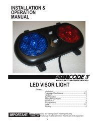
INSTALLATION& OPERATIONMANUAL3890 SERIESMASTERCOM <strong>SIRENS</strong>IRENS <strong>AND</strong> <strong>CONTROLS</strong>IMPORTANT:Contents:Introduction .......................................................... 2Standard Features ............................................... 2Unpacking & Pre-Installation ............................... 4Installation & Mounting ........................................ 5Set-Up and Adjustment ........................................ 8Operation............................................................ 11Maintenance ...................................................... 13Troubleshooting ................................................. 14Parts List (Replacement Parts / Exploded View)16Wiring Diagram .................................................. 20External Ignition Lead Relay ............................. 21Common MIC Option ......................................... 22Options ............................................................... 23Specifications..................................................... 23Notes .................................................................. 25Warranty ............................................................. 26Read all instructions and warnings before installing and using.INSTALLER This manual must be delivered to the end user of this equipment.1
IntroductionThe enhanced 3890 series siren is an improved series of electronic sirens that has been designed to meetthe needs of all emergency vehicles. This series of sirens incorporates the popular packaging and featuresof the original Mastercom siren with microprocessor based circuitry and MOSFET technology. Most of theoriginal Mastercom features are available along with many new added features that are not available on anyother <strong>Code</strong> 3 siren such as; Park Kill, Instant "ON", Adj. Backlighting, " Scroll " Mode and more.!WARNING!Sirens are an integral part of an effective audio/visual emergency warning system.However, sirens are only short range secondary warning devices. The use of a sirendoes not insure that all drivers can or will observe or react to an emergency warningsignal, particularly at long distances or when either vehicle is traveling at a high rate ofspeed. Sirens should only be used in a combination with effective warning lights andnever relied upon as a sole warning signal. Never take the right of way for granted. It isyour responsibility to be sure you can proceed safely before entering an intersection,driving against traffic, or responding at a high rate of speed.The effectiveness of this warning device is highly dependent upon correct mounting andwiring. Read and follow the manufacturer’s instructions before installing or using thisdevice. The vehicle operator should check the equipment daily to insure that all featuresof the device operate correctly.To be effective, sirens must produce high sound levels that potentially can inflict hearingdamage. Installers should be warned to wear hearing protection, clear bystanders fromthe area and not to operate the siren indoors during testing. Vehicle operators andoccupants should assess their exposure to siren noise and determine what steps, suchas consultation with professionals or use of hearing protection should be implemented toprotect their hearing.This equipment is intended for use by authorized personnel only. It is the user’s responsibilityto understand and obey all laws regarding emergency warning devices. The usershould check all applicable city, state and federal laws and regulations.<strong>Code</strong> 3, Inc., assumes no liability for any loss resulting from the use of this warningdevice.Proper installation is vital to the performance of the siren and the safe operation of theemergency vehicle. It is important to recognize that the operator of the emergencyvehicle is under psychological and physiological stress caused by the emergency situation.The siren system should be installed in such a manner as to: A) Not reduce theacoustical performance of the system, B) Limit as much as practical the noise level in thepassenger compartment of the vehicle, C) Place the controls within convenient reach ofthe operator so that he can operate the system without losing eye contact with the roadway.Emergency warning devices often require high electrical voltages and/or currents. Properlyprotect and use caution around live electrical connections. Grounding or shorting ofelectrical connections can cause high current arcing, which can cause personal injuryand/or severe vehicle damage, including fire.PROPER INSTALLATION COMBINED WITH OPERATOR TRAINING IN THE PROPERUSE OF EMERGENCY WARNING DEVICES IS ESSENTIAL TO INSURE THE SAFETYOF EMERGENCY PERSONNEL <strong>AND</strong> THE PUBLIC.Standard FeaturesThe enhanced 3890 series sirens consist of integrated controls and amplifier in a single package with 4 and6 circuit lighting controls available as well. The models are as follows:3892 - Primary Tones: Wail, Yelp, Hi-Lo, Air Horn- Secondary Tones: HyperYelp, HyperLo3892L4,L6- Primary Tones: Wail, Yelp, Hi-Lo, Air Horn- Secondary Tones: HyperYelp, HyperLo- 4 or 6 auxillary lighting controls22
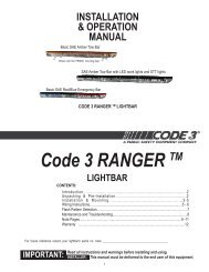
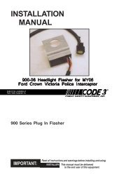
3894L6S same features as 3892L6 with anaddation of a rear panel connector toaccommodatea single microphone system.Horn RingSelectSlide SwitchSwitch ESwitch FSwitch ASwitch BSwitch CSwitch DGUN EMG SGN LTD RTD AThe following features are standard in the newstyle 3890 series (tones and sequences maydiffer by model number):WAILST<strong>AND</strong>BY YELPLIGHTINGRADIOHI-LOMANUAL AIR HORNMODEL 3894L6VOLUMEInstant-On- There is no " ON/OFF " switch. Selecting anysiren function, or keying the microphone will activate thesiren assuming the siren is connected directly to a nonignitionswitched source of +12V.SirenLock TM (L4 and L6 Models Only)- An interlock circuitbetween the siren and the light control circuits that permitsYOUR POLICE DEPT.'S NAME HERE (OPTION)Manual/AirHornPush-buttonsRotarySelectorSwitchFigure 1 - Control PanelMax. PAVolumeAdjustautomatic siren tones only when the progressive switch is in Level 3 or in Level 2 or 3 (user selectable - worksin conjunction with the horn transfer relay). This feature is used in jurisdictions that require warning lights to beon before the siren is activated.PA/RRBVolumeControlSwitchPark Kill- This feature deactivates the siren tones when the vehicle is shifted into park. Once PKILL isactivated the siren will remain deactivated until an action occurs such as moving the selector switch toST<strong>AND</strong>BY, returning lighting level switch to position one or keying the microphone. Any action will enable thesiren tones to function again with the exception of the auxillary lighting pushbuttons.On lighting models this alsodrops-out the Level 3 lighting output for a power- down mode when in park.Adjustable Backlighting- Backlighting is independent of siren power. Allows connecting to dimmer if desired.Radio Power- Allows user to power the two-way radio from the siren when the ignition is "OFF".Automatic Short Circuit Protection- The siren will sense a short circuit on the speaker terminals andautomatically go to standby until the fault is removed. Once the fault is removed the siren will return to normaloperation.Lighting Level "3 " Drop-out- When vehicle is shifted to PARK and the PKILL feature is connected, Level 3lighting will drop-out. This is indicated by the "red" LED exstinguishing. This is a power down mode and can bedefeated by setting the 4 -position rear dip switch to the PKILL "OFF" position on the lighting board.Scroll Mode- Setting the slide switch on the rear of the siren to the SCROLL position will put siren in scrollmode. This will allow "scrolling" through tones utilizing sharp taps on the horn ring, or a switch, via the Remotesiren input. In this mode holding the horn ring for prolonged durations will produce the Airhorn sound. SeeOPERATION section for further details.Hit-n-Go Mode - Setting the slide switch on the rear of the siren to the Hit-N-Go position will put the siren in theHit-n-Go mode.This mode will be most familiar to existing Mastercom users. A seven second override isstandard for all tones when activated by the Manual button or the Remote input.See OPERATION section fordetails.Automatic Siren Tones - Industry standard Wail, Yelp, and Hi-Lo tones.AIR HORN Tone - Electronic AIR HORN sound.Instant <strong>Public</strong> Address - <strong>Public</strong> Address override of all siren functions when the microphone Push-to-Talk keyis pressed.Status LED - An indicator LED, visible on the front panel that informs the operator of the status of his siren atall times.Radio Rebroadcast - Broadcast Two-way radio reception over siren speakers. These inputs are transformercoupled to prevent loading of the radio.3
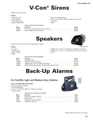
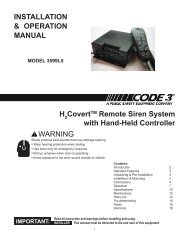
Remote Siren Switching - The siren accepts either a positive or a ground (earth) signal, usually from thevehicle's horn switch (or other user supplied switch), and remotely activates the MANUAL or AIR HORN (ifsupplied) function. Selection is made via the front panel slide switch.The siren is factory set for a GND(Earth) signal and may be reconfigured to accept a positive signal. See Set-up and Adjustments sectionfor details.Tone Priority/Manual Wail - The following tones are produced while pushing the MANUAL Push-button ortriggering the user-supplied REMOTE siren switch:Manual Wail when the MANUAL Push-button is depressed while the rotary switch is in the ST<strong>AND</strong>BY position.Yelp when the MANUAL Push-button is depressed while the rotary switch is in the WAIL position.HyperYelp when the MANUAL Push-button is depressed and the rotary switch is in the YELP position.HyperLo when the MANUAL Push-button is depressed and the rotary switch is in the HI-LO position.Noise Cancelling Microphone - Wired in microphone that is easily unplugged internally for service orreplacement.Power Distribution Section - A three level progressiveswitch for primary warning light system control plus 4 pushon/push-offauxiliary switches that are user convertible tomomentary action ('L4 models). The unit may also bepurchased with 6 auxiliary switches ('L6 models).Each auxiliary switch can be custom labeled with thesupplied label kit. Each label is backlit and increasesintensity when activated to alert the operator. Each positionof the progressive switch has its own indicator LED.Horn Ring Transfer - ('L models only) Built in horn transferrelay that may be activated at Levels 2 and 3 of the warninglight progressive switch. Point of activation is customerselectable with the rear panel DIP switch.Unpacking & Pre-installationFigure 2After unpacking your 3890 series siren, carefully inspect the unit and associated parts for any damage that mayhave been caused in transit. Report any damage to the carrier immediately!WARNING!All devices should be mounted in accordance with the manufacturer’s instructions andsecurely fastened to vehicle elements of sufficient strength to withstand the forces appliedto the device. Ease of operation and convenience to the operator should be the primeconsideration when mounting the siren and controls. Adjust the mounting angle to allowmaximum operator visibility. Do not mount the Control Head Module in a location that willobstruct the drivers view. Mount the microphone clip in a convenient location to allow theoperator easy access. Devices should be mounted only in locations that conform to theirSAE identification code as described in SAE Standard J1849. For example, electronicsdesigned for interior mounting should not be placed underhood, etc.Controls should be placed within convenient reach of the driver or if intended for twoperson operation, the driver and/or passenger. In some vehicles, multiple control switchesand/or using methods such as "horn ring transfer" which utilizes the vehicle horn switch totoggle between siren tones may be necessary for convenient operation from two positions.Controls should be placed within convenient reach* of the driver or if intended for twoperson operation the driver and/or passenger. In some vehicles, multiple control switchesand/or using methods such as “horn ring transfer” which utilizes the vehicle horn switch totoggle between siren tones may be necessary for convenient operation from two positions.4
Installation & MountingThe 3890 series siren may be mounted above the dash, below the dash, on a tunnel or in a rack withthe mounting bracket (bail) and the hardware supplied (see Fig. 2). Ease of operation andconvenience to the operator should be the prime consideration when mounting the siren andcontrols.movement away fromthe seat back or loss of eye contact with theThe bail is mounted to the siren chassis by means of the "T" slot in the side of the unit and the 1/4-20carriage bolts, washers, and nuts supplied. See Figure 2 for assembly and positioning details. Notethat once the unit is installed, removal involves only loosening, not removing, the acorn nuts. Use of1/4 - 20 HEX head bolts can damage slots and prevent easy removal of the unit.NOTE: Set-ups and adjustments will be made in subsequent steps, depending upon the model andoptions purchased, that may require access to the rear area of the unit. Plan the installation andwiring accordingly.Amplifier ConnectionsSiren Amplifier Connector - As a standard feature, the Siren and Auxiliary sections ('L4 & 'L6models) of your unit come equipped with a combination plug-in terminal block/connector. Toterminate the wires, strip approximately 1/4" of insulation from the end of each wire and insert it inthe appropriate hole in the terminal block. Recommend using a screwdriver with a 1/8" wide bladewith a 6" shaft such as an Xcelite(C) R186 or equivalent rather than a 4 1/2" adjustment screwdriverto ensure proper torque on the screws. Tighten the set-screw and proceed to the next connection.Should you ever have to remove the unit, pull the terminal block straight out. It will unplug fromthe unit, leaving the wiring in place.!WARNING!Larger wires and tight connections will provide longer service life for components. For highcurrent wires it is highly recommended that terminal blocks or soldered connections be usedwith shrink tubing to protect the connections. Do not use insulation displacementconnectors (e.g. 3M ® ) Scotchlock type connectors). Route wiring using grommets andsealant when passing through compartment walls. Minimize the number of splices toreduce voltage drop. High ambient temperatures (e.g. underhood) will significantly reducethe current carrying capacity of wires, fuses, and circuit breakers. Use "SXL" type wire inengine compartment. All wiring should conform to the minimum wire size and otherrecommendations of the manufacturer and be protected from moving parts and hot surfaces.Looms, grommets, cable ties, and similiar installation hardware should be used to anchorand protect all wiring. Fuses or circuit breakers should be located as close to the powertakeoff points as possible and properly sized to protect the wiring and devices. Particularattention should be paid to the location and method of making electrical connections andsplices to protect these points from corrosion and loss of conductivity. Ground(Earth)terminations should only be made to substantial chassis components, preferablydirectly to the vehicle battery. The user should install a circuit breaker sized toapproximately 125% of the maximum Amp capacity in the supply line to protect againstshort circuits. For example, a 30 Amp circuit breaker should carry a maximum of 24 Amps.DO NOT USE 1/4" DIAMETER GLASS FUSES AS THEY ARE NOT SUITABLE FORCONTINUOUS DUTY IN SIZES ABOVE 15 AMPS. Circuit breakers are very sensitive tohigh temperatures and will "false trip" when mounted in hot environments or operatedclose to their capacity.5
!WARNING!CONNECTION OF A 58 WATT SPEAKER TO THE SPKR TERMINAL WILL CAUSE THESPEAKER TO BURN OUT, <strong>AND</strong> WILL VOID THE SPEAKER WARRANTY!The sound projecting opening should be pointed forward, parallel to the ground, and notobstructed or muffled by structural components of the vehicle. Concealed or under-hoodmountings in some cases will result in a dramatic reduction in performance. To minimizethis reduction, mount the speaker so the sound emitted is projected directly forward andobstruction by vehicle components such as hoses, brackets, grille, etc. is minimized.Electromechanical sirens and electronic siren speakers should be mounted as far from theoccupants as possible using acoustically insulated compartments and isolation mountings tominimize the transmission of sound into the vehicle. It may be helpful to mount the deviceon the front bumper, engine cowl or fender; heavily insulate the passenger compartment; andoperate the siren only with the windows closed. Each of these approaches may causesignificant operational problems, including loss of siren performance from road slush, increasedlikelihood of damage to the siren in minor collisions, and the inability to hear the sirens on other emergency vehicles.APPROPRIATE TRAINING OF VEHICLE OPERATORS IS RECOMMENDED TO ALERTTHEM TOTHESE PROBLEMS <strong>AND</strong> MINIMIZE THE EFFECT OF THESE PROBLEMSDURING OPERATIONS.Terminal Block Connections10 Position Terminal Plug- ( see wiring diagram page 20 )COM - Connect to the terminal marked "1" of one 100 W ( 11 ohm ) speaker.SPKR - Connect to the terminal marked "2" of the 100 W ( 11 ohm ) speaker..NOTE: An optional 200 W version is available. This will enable the user to connect two 100 Wspeakers in parallel. Correct phasing is important and can be accomplished by connecting bothspeaker terminals marked " 1 " to the COM terminal and both speaker terminals marked " 2" to theSPKR terminal.REMOTE - Remote switch (Horn ring or foot switch). Circuit can be configured for both ground(earth) or positive signals. A horn ring transfer circuit is standard in all 3940 series "L" models.Connect to the "REMOTE" terminal on the Lighting Control Section terminal block. Unit isconfigured for a ground ( earth ) at the factory. See page 7 for details on configuring for a +12Vinput.BLTG- Provides +12V to siren backlighting. Connect to a vehicle circuit that is powered when theignition switch is " on ". If backlighting dimming is desired, connect to the dash lights' circuit.Caution- If connected to the battery the backlighting will be active at all times.PKILL- This feature automatically deactivates siren tones when the vehicle is shifted into PARK.On models with lighting control Level 3 will " drop-out " if this feature is enabled via the rear paneldip switch. Siren tones will be disabled until the vehicle is shifted out of PARK and the front panelselector switched is either returned to standby ( or another function is selected ) or the lightinglevel control is returned to level 1.This circuit is activated by a negative signal. Connect this input to a circuit that is GROUNDED(Earth) when the vehicle is shifted into PARK. It is the installer's responsibility to determine anappropriate location in the vehicle circuitry to connect this wire.RRB - Connect to one side of the two-way radio speaker.RRB - Connect to the second side of the two-way radio speaker.EXPWR - Connect directly to +12V terminal of the battery or a non-ignition switched source of +12Vcapable of supplying a minimum of 10 Amps.6
RPWR- Provides +12V to the two-way radio with the ignition on / off . Connect the +12V power leadfrom the radio to this terminal. This is a 10 Amp maximum current output.InterClear ® (Optional) - Connect to the device or circuit that is to be activated by the InterClearfeature.The InterClear circuit is internally current limited at 1 Amp. Should your requirements requirehigher currents, use the InterClear Power Booster Kit (# INTBS), available from your <strong>Code</strong> 3 supplier.1/4" Male Quick-Connect Printed Circuit Board Terminals+12V - Connect to a positive +12 volt DC source. It is recommended that the user protect this wirewith a 10 Amp fuse(20 Amp for 200w option) or circuit breaker located at the source. Use #14 gaugewire terminated with 1/4" female, fully insulated quick-connect terminals only.NEG - Connect to the negative terminal of the battery. This supplies ground (earth) to the siren.Use #14 gauge wire terminated with 1/4" female, fully insulated quick-connect terminals only.Power Distribution Connections ( "L" Models)A #8 stud is provided on the rear of the unit and is intended for use ONLY as a convenient ground(earth) " tie-point " for the light bar wiring. It is not an adequate ground (earth) for the siren orthe light bar. It is recommended all ground (earth) wires attached here be terminated with acrimp-on ring terminal.11-Position Terminal Plug - Rear Panel- (See Wiring Diagram page 20)IMPORTANT!Remember auxillary outputs A,B,D on L4 models and A,B,D,E,F on L6 models can supply amaximum of 20 Amps each for a combined total of 30 Amps. Install appropriate fuses in eachoutput wire as close to the siren as possible.SW D - Connect to the load to be controlled by Auxiliary Switch "D".SW B - Connect to the load to be controlled by Auxiliary Switch "B".SW C NO - Connect to the load to be controlled by the normally-open contact on Auxiliary Switch"C".SW C NC - Connect to the load to be controlled by the normally-closed contact on Auxiliary Switch"C".SW C COM - Common or power feed for Auxiliary Switch "C". Terminals are a SPDT circuit that maybe connected as a momentary (or timed momentary with option) ignition controlled circuit, or used forswitching auxiliary circuits. It will Handle 10 Amps, and should be protected with a fuse at the batteryif individually fed. Can also be connected to a ground source if the load on SWC NO or SWC NC isalready connected to a 12V source and needs a ground input to activate it.SW F - ('L6 models only) Connect to the load to be controlled by Auxiliary Switch "F".SW A - Connect to the load to be controlled by Auxiliary Switch "A".SW E - ('L6 models only) Connect to the load to be controlled by Auxiliary Switch "E".HORN RING - Connect to the wire coming from the vehicle horn switch at the steering wheel.HORN - Connect to the vehicle horn or vehicle horn ring relay.7
REMOTE - Connect to the Remote terminal on the Siren Amplifier Connector.Lighting Models Only ( L versions )#8 GAUGE RED WIRE PIGTAIL - provides power to the 3 Level, progressive lighting outputs only.The wire can be ordered with an optional connector to allow for convenient removal. The connectorshould be soldered to each wire, NOT crimped. This connection is designed to provide 50 ampservice and therefore nothing smaller than #8 guage wire should be connected to it.The circuit breakerused should be sized for the actual load of the lighting used and located as close to the batterypositive as possible. For quick disconnection option on 8 AWG wire see "lighting switch connector"on page 23.4 Position Screw-type Terminal Block ConnectorImportant!The total combined current for the auxillary outputs A,B,D on L4 models and A,B,D,E,F on L6models must not exceed 30 Amps total.+12VAUX - Connect to the positive terminal of the battery with 30 Amp circuit protection. Locate thefuse or circuit breaker at the battery and use #10 gauge wire minimum. This terminal powersswitches A,B and D on L4 models and A,B,D,E and F on L6 models, and also supplied power to thesiren lock & light alert circuits on both models.LEVEL 1 - Connect to the first level of warning lights (Green LED) position "1" on level switch.LEVEL 2 - Connect to the second level of warning lights (Yellow LED) position "2" on level switch.LEVEL 3 - Connect to the third level of warning lights (Red LED) position "3" on level switch.NOTE: LEVEL 1, LEVEL 2, LEVEL 3, switch progressively. Switch position 1 provides +12 volts atLevel 1 terminal. Switch position 2 provides +12 volts at terminals 1 and 2. Switch position 3provides +12 volts at terminals 1, 2, and 3.SET-UP <strong>AND</strong> ADJUSTMENTAll of the adjustments, except MAXIMUM P.A. ADJUSTMENT, and set-up switches areaccessible from the rear of the unit. Make these adjustments and position the set-up switches priorto placing the unit inside their bail bracket (see wiring diagram, page 20).Audio AdjustmentsRadio Rebroadcast Adjustment - Place the selector switch in the RADIO position. The trimmerlocated on the rear panel of the siren sets the maximum level RRB will reach with the knob fullyclockwise. To adjust properly, set the volume knob fully clockwise and adjust the trimmer such thatnormal two-way radio volume inside the vehicle produces the desired volume outside the vehicle.Maximum P.A. Volume Adjustment - This trimmer ( located on the front panel next to the volumecontrol knob ) sets the maximum level that the P.A. volume will reach with the front panel VOLUMEcontrol in the fully clockwise position.To adjust properly, set the front panel volume control fullyclockwise and adjust the trimmer while keying the microphone until the maximum volume out of thespeaker is such that there is no feedback and is intelligible. (See Figure 1)8
Remote InputThe remote input can be configured to accept either a positive +12V or negative GND ( Earth ) signalfor actuation. All new style 3890 series sirens are shipped set-up to accept the GND (Earth) signalfrom the vehicle HORN SW present on most vehicles. To reconfigure this as a +12V signal the rearplate must be removed ( see assembly explosion page 19 ). Place both jumpers towards the "+ "position. Refer to Detail "A" shown above for a complete illustration.4-Position DIP SwitchGently set the SirenLock, PKILL and LightAlert set-up switches to the desired position with a pencilpoint or some other pointed object. These switches are present even if LightAlert were not specified.If switched on, all of the tones except AIR HORN, mute until the Warning Light Switch is in either theLevel 3 or the Level 2 or 3 positions.SirenLock - In position "3" the siren tones are allowed to sound and the horn ring relay transferswhen the Warning Light switch is placed in the Level "3" position. In position "2,3" the siren tonesare allowed to sound and the horn ring relay transfers when the Warning Light switch is placed ineither Level 2 or in Level 3 position.LightAlert - When in the ON position, enables the LightAlert tone, which alerts the operatoraudibly when any lighting switch is activated. When in the OFF position, defeats the LightAlerttone.PKILL- When vehicle is shifted to PARK lighting level 3 will " drop-out " if this switch is in the "on"position. This is intended to reduce power consumption while vehicle is not moving. If it is notdesired to have level 3 "drop-out" this switch should be set to the " OFF " position on the dipswitch. This will not defeat the PKILL feature on the siren, but will defeat the level 3 DROPout.9
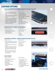
Siren Mode Selector Slide SwitchThe siren has two distinct modes, Hit-N-Go and Scroll. Set rear panel slide switch to the desiredmode by sliding left or right. See operation section for detailed opertion in each mode.Push-Button Conversion('L models only)Switches A-F can be set up as momentary (only onwhile pushed), or push-on/push-off. They can beconverted as follows:1. Disconnect all connectors and wiring to unit.Remove siren from the vehicle if it is installed.2. Remove the screw holding the rear cover plate to thesiren tray.3. Remove the (4) screws holding the bezel to theextrusion.Switch withpin intactGrasp pinat this end4. Slide the front panel/tray assembly forward out of theextrusion.5. Grasp the rear edge of the Power Distribution CircuitBoard (on top), slide it back and lift it free from the (4)Rotate pintoward front ofswitchFigure 3Lift pinout andstore forfurtherusestandoff fasteners holding it to the lower circuit board. Caution: The circuit board is still attached.See steps 6 & 7 below.6. Note the orientation of the circuit board four-pin connector and remove.7. Do the same with the lighting level switch four-pin connector.8. See Figure 3 for information on converting the switch. Once converted the switch may beconverted back again if the toggle pin is not lost.9. Re-assemble the siren in the reverse order. Note correct orientation of the four and three-pinharness connectors.Custom LabelingLabels supplied with the L4 and L6 models should be selected and placed in the appropriate windows.See fig 1 for front view of siren, for switches A-F window designations. The windowscan be accessed by removing the (4) screws holding the bezel to the siren chassis extrusion.!WARNING!"Wail" and "Yelp" tones are in some cases (such as in the state of California)the only recognized siren tones for calling for the right of way. Ancillary tonessuch as "Air Horn", "Hi-Lo", "Hyperyelp", and "Hyperlo" in some cases do notprovide as high a sound pressure level. It is recommended that these tones beused in a secondary mode to alert motorists to the presence of an emergencyvehicle.10
P.A. VOLUME Knob - This control adjusts the level of the P.A. audio produced when keying the microphoneand speaking into it. This control also controls the Radio Re-broadcast level when in the " Radio " position (seeSET-UP, Radio Rebroadcast Adjustment on p. 8).OperationIMPORTANT !The Mastercom Series has two distinct modes of operation. These are the Hit-N-Go mode and theSCROLL mode. The desired mode of operation can be selected via the rear panel slide switch. Eachmode will effect the siren operation as described below. The Hit-N-Go mode should be most familiarto existing Mastercom users.The siren tones will be deactivated when the vehicle is in "PARK" if the PKILL feature has beenconnected. To test the siren tones the vehicle must not be in "PARK". The following assumes thatPKILL has not been activated.Switch Operation - Hit-N-Go Mode SelectedFunction Selector Switch (Center Knob)RADIO - In the RADIO position, the audio from the 2-way radio is rebroadcast over the siren speaker. Thesiren tones (Wail, Yelp, & Hi-Lo) do not operate in this position. In addition, power is routed to the two-wayradio via the RPWR pin on the rear panel connector. The EXPWR pin must be wired to the battery positive ,and the two-way radio power connected to the RPWR pin.ST<strong>AND</strong>BY - This is the standby mode. If the MANUAL button is depressed , and the vehicle is not inPARK, the Manual wail tone will ramp up until it reaches a peak then ramp down when released. If the AIRHORN button is depressed, the Air Horn sound will be produced.WAIL - This position produces the Wail tone. Depressing the MANUAL button or activating the remote inputwill now produce the Yelp tone for 7 seconds. Depressing the AIR HORN button will produce the Air Hornsound and when released will return siren to Wail tone.YELP - This position produces the Yelp tone. Pushing the MANUAL button or activating the remote input willnow produce the HyperYelp tone for 7 seconds. If the AIRHORN button is pushed, the Airhorn sound will beproduced and when released will return the siren to Yelp.HI-LO - This position produces the Hi-Lo tone. Pushing the MANUAL button or activating the remote inputwill now produce the HyperLo tone for 7 seconds. If the AIRHORN button is pushed, the Airhorn sound willbe produced and when released will return siren to Hi-Lo.Push-to-Talk (PTT) Microphone Switch - Keying the microphone will automatically override whatevermode the siren is in and broadcast public address messages over the siren speaker. PTT operates in allpositions of the Selector switch.MANUAL Pushbutton Momentary Switch -Has no effect when the selector switch is in RADIO, producesthe effects described above for each selector position.AIR HORN Pushbutton Momentary Switch- Produces the Air Horn tone in all selector switch settingsexcept RADIO.SLIDE SWITCH - The slide switch located between the AIR HORN and MANUAL buttons selects thefunction for the REMOTE (external switch) circuitry. When the switch is to the right, the Horn Ringcircuitry remotely "depresses" the AIR HORN button and it produces the effects outlined above. When theslide switch is to the left, it allows the REMOTE circuitry to remotely "depress" the MANUAL pushbutton.This causes the effects described above to occur.11
Switch Operation - Scroll Mode SelectedThe " Scroll " mode is designed to allow the user to scroll through all the tones including Airhorn by utilizingthe Remote input on the siren. This will usually be connected to the vehicle Horn Ring circuit. When thesiren selector switch is placed in either Wail or Yelp ( and Horn Ring transfer has occured ) the user canuse the Horn Ring to sequence through Wail,Hyperyelp and Yelp by applying a quick, sharp tap on the horn.Additional taps will scroll the siren to the next tone. Depressing the horn ring for longer periods will produce" Airhorn". After releasing the vehicle's horn ring, the siren will return to the selected tone.Function Selector Switch (Center Knob)RADIO - In the RADIO position, the audio from the 2-way radio is rebroadcast over the siren speaker. Thesiren tones (Wail, Yelp, & Hi-Lo) do not operate in this position. In addition, power is routed to the two-wayradio via the RPWR pin on the rear panel connector. The EXPWR pin must be wired to the battery positive ,and the two-way radio power connected to the RPWR pin.ST<strong>AND</strong>BY - This is the standby mode. If the MANUAL button is depressed the Manual wail tone will rampup until it reaches a peak then ramp down when released. If the AIR HORN button is depressed, the AirHorn sound will be produced. The siren cannot be scrolled in this position.WAIL - This position produces the Wail tone. Depressing the MANUAL button will now produce Manual wailtone and ramp up until released. Depressing the AIR HORN button will produce the Air Horn sound.The sirencan be scrolled in this position as described above.YELP - This position produces the Yelp tone. Pushing the MANUAL button will now produce the Manual wailtone and ramp up until released. If the AIRHORN button is pushed, the Airhorn sound will be produced.Thesiren can be scrolled from this position as decribed above.HI-LO - This position produces the Hi-Lo tone.Pushing the MANUAL button will now produce the HyperLotone for 7 seconds. If the AIRHORN button is pushed, the Airhorn sound will be produced and whenreleased will return siren to Hi-Lo.The siren cannot be scrolled from this position.Push-to-Talk (PTT) Microphone Switch - Keying the microphone will automatically override whatevermode the siren is in and broadcast public address messages over the siren speaker. PTT operates in allpositions of the Selector switch.MANUAL Pushbutton Momentary Switch -Has no effect when the selector switch is in RADIO, producesthe effects described above for each selector position.AIR HORN Pushbutton Momentary Switch - Produces the Air Horn tone in all selector switch settingsexcept RADIO.SLIDE SWITCH - The slide switch located between the AIR HORN and MANUAL buttons selects thefunction for the REMOTE (external switch) circuitry. When in the "Scroll " mode this switch has noeffect unless in ST<strong>AND</strong>BY or the Hi-Lo position. When this is the case the switch functions asfollows:When the switch is to the right, the Horn Ring circuitry remotely "depresses" the AIR HORN button and itproduces the effects outlined above. When the slide switch is to the left, it allows the REMOTE circuitry toremotely "depress" the MANUAL pushbutton. This causes the effects described above to occur.LED STATUS INDICATOR - The green LED status indicator indicates the siren is on when lighted. The LEDwill remain off unless a siren tone or air horn or PA or radio output is selected.12
-For 'L4 & 'L6 Models Only-WARNING LIGHTS 3 LEVEL PROGRESSIVE SLIDE SWITCH:POSITION 1 - Supplies power to Lighting Level 1, illuminates Green LED and activates LightAlert if supplied.POSITON 2 - Supplies power to Lighting Levels 1 & 2. illuminates Green & Yellow LED's and activatesLightAlert and SirenLock options if supplied.POSITION 3- Supplies power to Lighting Levels 1,2, & 3. Illuminates Green, Yellow, and Red LED's; andactivates LightAlert and SirenLock if supplied.Auxiliary Switches:AUXILIARY SWITCH "A" - Supplies power to the load connected to terminal SW A.AUXILIARY SWITCH "B" - Supplies power to the load connected to terminal SW B.AUXILIARY SWITCH "C" - Operates circuit connected to terminals SWC NO, SWC NC, SWC COM.Optional functions a momentary activation or a 5 sec. timed switch.AUXILIARY SWITCH "D" - Supplies power to the load connected to terminal SW D.-For 'L6 Models Only-AUXILIARY SWITCH "E" - Supplies power to the load connected to terminal SW E.AUXILIARY SWITCH "F" - Supplies power to the load connected to terminal SW F.NOTE: All switches have their own individual LED indicating that the circuit is On. All switches will activatethe LightAlert feature if it is supplied.LightAlert - The LightAlert option will produce an audible "beep" on a periodic basis if the Warning LightSwitch or any of the Auxiliary Switches are on. A rear accessible circuit board mounted DIP switch isprovided to defeat this option.SirenLock - The SirenLock, when not defeated by means of a rear panel accessible switch, allows siren tones(Wail, Yelp, and Hi-Lo) to be produced only when the Warning Light Switch is in the Lighting Level 2 (Green andYellow LED's) or Lighting Level 3 (Green, Yellow, and Red LED's) position (switch selectable via a rear panelaccessible switch). Air Horn, Radio Rebroadcast, and <strong>Public</strong> Address are unaffected by this option.MAINTENANCEYour <strong>Code</strong> 3 ® 3890 series siren has been designed to provide trouble free service. In case of difficulty, seeTroubleshooting (page 14,15 ). Also check for shorted or open wires. The primary cause of short circuitshas been found to be wires passing through firewalls, roofs, etc. If further difficulty persists, contact thefactory for troubleshooting advice or return instructions. <strong>Public</strong> <strong>Safety</strong> <strong>Equipment</strong>, Inc. maintains a completeparts inventory and service facility at the factory and will repair or replace (at the factory's option) any unitfound to be defective under normal use and in warranty. Any attempt to service a unit in warranty by anyoneelse other than a factory authorized technician without express written consent by the factory, will void thewarranty.Units out of warranty can be repaired at the factory for a nominal charge on either a flat rate or parts andlabor basis. Contact the factory for details and return instructions. <strong>Public</strong> <strong>Safety</strong> <strong>Equipment</strong>, Inc. is notliable for any incidental charges related to the repair or replacement of a unit unless otherwise expresslyagreed to in writing by the factory.13
TROUBLESHOOTING(Refer to wiring diagram page 20)PROBLEM PROBABLE CAUSE REMEDYNO SIREN OUTPUT.INTERNAL OREXTERNAL 10AOR 20AOPTION FUSE BLOWS.NO OUTPUT FROMSPEAKER, TONESHEARD INSIDEAMP. MODULE.SIREN TONESVOLUME TOOLOW/GARBLED.HIGH RATE OFSPEAKER FAILURE.A. PARKKILL ENGAGEDB. SIRENLOCK EXGUAGEDC. SHORTED SPEAKER ORSPEAKER WIRES. SIREN IN OVERCURRENT PROTECTION MODE.A. AMPLIFIER POWER WIRESREVERSED POLARITYB. 200W LOAD CONNECTED TO100W UNIT FOR 10 AMP FUSEA. SPEAKER NOT CONNECTED/OPEN CIRCUIT IN SPEAKERWIRINGB. DEFECTIVE SPEAKER(S)A. LOW VOLTAGE TO SIRENAMPLIFIERB. HIGH RESISTANCE IN WIRING/DEFECTIVE SPEAKERC. SPEAKERS PHASEDIMPROPERLY (200W OPTION)A. HIGH VOLTAGE TO SIRENB. 58 WATT SPEAKER CONNECTEDTO 100 WATT TAP. 58 WATT NOTALLOWED.A. DISENGAGEPARKKILLB. SELECT LEVEL 3LIGHTINGC. CHECKCONNECTIONSA. CHECK POLARITYB. REMOVE ONESPEAKER ON 100WUNIT.A. CHECK SPEAKERWIRINGB. REPLACESPEAKER(S)A. CHECK WIRING FORBAD CONNECTIONS/CHECK VEHICLECHARGING SYSTEMB. CHECK SPEAKER(S)WIRING/REPLACESPEAKER(S)C. REFER TO PAGE 6FOR PROPERPHASINGA. CHECK VEHICLECHARGING SYSTEMB. USE CORRECTSPEAKERSIREN CONTINUESTO OPERATE FOR7 SEC. AFTERMANUAL BUTTON/HORN RING ISRELEASED.INTERCLEAR WILL NOTPOWER AUXILIARYDEVICES. IF OPTIONIS INSTALLED.P.A. VOLUME LOW ORNO P.A. AT ALL.VOLUME CONTROLFULLY CLOCKWISE.A. "HIT-N-GO" FEATURE ENGAGED.NORMAL OPERATIONA. THERE IS A SHORT IN THEWIRING, OR THE LOAD ISGREATER THAN 1 A.A. DEFECTIVE MICROPHONEB. MAXIMUM P.A. VOLUMETRIMMER MISADJUSTED. SEE SET-UP <strong>AND</strong> ADJUSTMENT SECTION.C. MICROPHONE NOTCOMPLETELY PLUGGED IN.D. COMMON MICROPHONECIRCUIT NOT PROPERLY WIRED.E. INCORRECT MICROPHONE.A. CHECK FORSHORTS. INSTALLINTERCLEARBOOSTER KIT (PART#INTBS)A. REPLACEMICROPHONEB. REFER TO SET-UP<strong>AND</strong> ADJUSTMENTSECTIONC. PLUG MICROPHONEIN SECURELYD. CHECK WIRING14
TROUBLESHOOTING(Refer to wiring diagram page 20)PROBLEM PROBABLE CAUSE REMEDYRRB VOLUME LOW, ORNO RRB AT ALL.VOLUME CONTROLFULLY CLOCKWISE.A. MAXIMUM RADIOREBROADCAST TRIMMER MIS-ADJUSTEDB. RRB WIRES NOT CONNECTEDTO TWO-WAY RADIO EXTERNALSPEAKERA. REFER TO SET-UP<strong>AND</strong> ADJUSTMENTSECTIONB. CHECK RRBCONNECTIONSSIREN SOUNDS BYITSELFPOWER DISTRIBUTIONSECTION NOTWORKINGSIREN RUNSPROPERLY BUT SHUTSDOWN WHILERUNNING, THENSTARTS RUNNINGAGAIN AFTER A FEWMINUTESA. REMOTE SWITCH (HORN RING)WIRING FROM TERMINAL REMOTESHORTING TO POSITIVE OR TOGROUND (EARTH).A. SUPPLY FUSE OPENB. SIREN NEGATIVE TERMINALNOT GROUNDEDA. VEHICLE CIRCUIT BREAKERSNOT RATED PROPERLY, <strong>AND</strong> AREOVERHEATING, OR ARE NOTFUNCTIONING PROPERLYA. CHECK WIRING FORANY SHORTING.A. REPLACE FUSE.B. RECONNECTNEGATIVE TERMINALTO GROUND.A. REFER TOSPECIFICATIONSSECTION, PAGE 18.USE A BREAKER WITH1.25x THE AMPERAGERATING FOR THEWATTAGE BEINGUSED.15
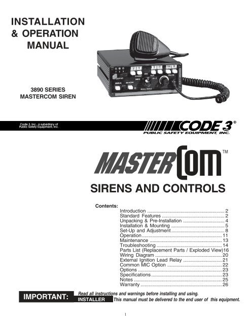
Parts ListRef No. Description (SEE FIGURE 4 PAGE 19) Part No. Qty.1 #6 x 1/2, Pan Hd Phil, Sheet Metal Screw T02797 82 Bezel T03542 13 #4 - 40 x 3/8", Pan Hd. Phil., Machine Screw T06937 24 Selector Knob T03537 15 Selector Knob Insert T03538 16 #4 - 40 x 3/8, Flat Hd Phil., Machine Screw T01011 27 Switch Knob T01917 18 Molded Guide T01916 19 Faceplate Label - 1Model 3892 T06997Model 3892L4 T06996Model 3892L6 T0699510 Faceplate T08657 111 Horizontal Rotary Switch T01116 112 Volume Control Knob T03536 113 3/8 - 32 x 1/2 x .090" Nut T01082 214 Custom Label Window T03539Models 3892L4 2Models 3892L6 315 Strain Relief T07310 1Models 3892, 3892L4, 3892L616 Microphone Wired T07311 1Models, 3892, 3892L4, 3892L617 Microphone, Plug-in T07309 116
18 Fish Paper Gasket T01363 419 Spacer T08659 120 Transistor Insulating Pad T06363 221 #4 - 40 Nylon Insert Stop Nut T03594 222 Microphone Jack (Option) T06147 123 Siren Amp. Circuit Board T50002 1Models 3892, 3892L4, 3892L624 Circuit Board Standoff T05172 425 #6 - 32 Rd Hd Phil., Machine Screw T01030 426 Lamp, Miniature, 14VDC T10805 127 Lighting Pushbutton Actuator T03540Models 3892L4 6Models 3892L6 8Model 3892 228 Lighting Circuit Board T50005 1Models 3892L429 Lighting Circuit Board T50004 1Models 3892L630 E - Tray Pemserted T03100 131 Tinnerman Clip T01058 132 Label Set T10859 133 Chassis S55133 134 Mounting Bail T08660 135 Acorn Nut T00183 436 #8 - 32 x 5/8, Hex Hd, Machine Screw T00763 137 Backplate 117
Model 3892Model 3892L4Model 3892L6S71332S71328T0865838 Airbag Warning Label T09937 139 1/4 Internal Tooth Star Lock Washer T06935 440 #12 Flat Washer T01295 441 C - Bolt, 1/4 - 20 T06138 442 Internal Harness T10920 143 #6 x 3/8 Hex Hd, Sheet Metal Screw T01031 144 Fuse, Blade Type Term., 10A T06313 1Fuse, Blade Type Term., 20A T01031 145 #8 - 32 Kep Nut T00674 218
2424292732262524283930434033354142344437 383633314546Figure 419
Installer: Please record model number and serial number on page 25.For technical assistance see page 25.Figure 420
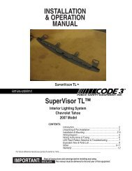
forExternal Ignition Lead Relay3890 Series Siren SystemsDESCRIPTION:Normal installation procedure requires the siren’s +12VDC power connection to be connected to the vehicle’signition circuit so that the ignition key must be in the on position for the system to operate. In cases wherevehicle security is a consideration it may be desirable to connect the siren system directly to the vehicle’sbattery in order to allow the siren and lighting control to be operated with the vehicle’s ignition switch in the offposition. This requires that the siren’s +12VDC power connection be routed through the normally closed (NC)contacts of a SPDT relay (user supplied). This is easily accomplished using the wiring method described below.OPERATION:Refer to the appropriate user instruction manual for details on the configuration and operation of theMasterCOM Siren System.WIRING:The basic connections are shown in Fig. 1 below. Please note that other equivalent relays and vehicles ofdifferent makes and models may require slightly different connections. Mount and wire the siren amplifier incompliance with the instructions in the user manual. Read and comply with all safety warnings. Refer to thevehicle manufacturer’s wiring diagram to determine the location and wire color of the start circuit. Securelymount the external relay. Use the appropriate wire size as indicated in Fig. 1, and insure that all wiring isproperly terminated and secured in a manner that does not interfere with other systems within the vehicle.+12VDC FROM BATTERYPSE P/N 680BOSCH 0 332-204-150OR EQUIVALENT20A FUSE(USER SUPPLIED)C (30)NC (87a)TO SIREN +12VDCQUICKSLIDE CONNECTORN0 (87)WIRE SIZE - 12 AWGWIRE SIZE - 12 AWG(85)TO VEHICLE START CIRCUITR/LB WIREON FORD CROWN VICWIRE SIZE - 18 AWG(86)GROUNDExternal relay wiring to allow electronic sirenand lighting control to operate directly fromvehicle battery (vehicle ignition OFF) andprovide ignition reset to siren during vehicle restart.Fig. 621
CUSTOMER SUPPLIEDDOUBLE POLE DOUBLETHROW (DP/DT) RELAYCOMMON MIC OPTIONFIGURE 722
OptionsLighting Switch Connector- Connectors which when soldered to the #8 wire and the user supplied power wireoffers quick disconnect service.200W Speaker Output - An optional 200 watt version is available. This enables the user to connect two 100wspeakers in parellel.No HI-Low Siren Tones - "wail" and "yelp" tones are in some cases (such as in the state of California) the onlyrecognized siren tones for calling for the right of way.Instant Yelp - This porduct is provided with an INSTANT YELP feature which allows the user to select theYELP tone instantly by depressing the vehicles's horn switch.Remote MIC Jack - A plug-in microphone jack in lieu of the standard wired-in microphone may be specified. Aplug-in noise-anceling microphone (p/n T07309) must be ordered seperately if needed.LightAlert TM (L4 and L6 Models Only)- An audible alarm pulse that indicates that either the primary warningsystem or one of the auxiliary control circuits is on. User defeatable.InterClear ® This unique feature can be used to activate additional warning lights for 7 seconds when in anHit-N-Go override or " scrolling " by pushing a single button or the vehicle horn ring, thus allowing an additionallevel of warning in situations such as intersections without the operator having to take his hands off the wheelor his eyes off the road.InterClear Booster Kit (part#intbs) Increases interclear option's output capability for loads greater than 1 amp.Custom Engraving (CUSENG) - The lower portion of the faceplate can be engraved with department name orother information.Air Horn only - This option disables the primary and secondary siren tones while still enabling the Air horntone, Radio Rebroadcast and PA outputs. The promary warning and auxiliary lighting controls remainuneffected.SpecificationsSiren SectionInput Voltage -10 to 16 VDC, negative ground (earth).(Note: Operation above 15 VDC for an extended period of time may result in speaker damage.)Operating Current: 8 Amps @ 13.6V with 11-ohm load ( 100 W Spkr )For optional 200 Watt operation: 14 Amps @ 13.6V with 5.5-ohm load ( 2- 100 W Spkr )Note: There is no 58 Watt speaker connection available.Standby Current:12 mA excluding backlightingCycle Rate: WAIL - 11 cycles/minute.YELP - 200 cycles/minute.Voltage Output ( approx. ) 64 V peak-to-peakAudio SectionAudio Response: 3 dB down points - 500 to 3000 hz.1000 hz. 0 dB ReferenceAudio Distortion: 10% or less below clipping.23
Lighting Section ("L" Models Only)Warning Light Control: Progressive switching, 3 levels50 Amps. maximum combined total to #8 wireAudible alarm (optional).Level 1Level 2Level 330A maximumGreen LED Indication30A maximumYellow LED Indication30A maximumRed LED indication.Auxiliary Control - SPST ( Aux. Switches A, B,C,D,E, F )Accessory Switch operation - Push-on/off convertible to momentary operation.Independent circuits - 4 ('L4), 6 ('L6).30 Amps. maximum combined total20 Amps. maximum load for any single output A,B,C,D,E or FGreen LED indication.Audible alarm (optional).Horn Transfer Relay - SPDT:Activated in Level 2 or Levels 2 & 3 (User selectable).10 Amps. maximum connected load.24
For Technical assistance phone (314) 426-2700 and then press option 2 when you hear the recording.For Technical Service direct FAX (314) 429-2962.or www.code3pse.comPlease have model number and the serial number of the unit handy before calling.Model number 394_L_Serial NumberNOTES:25
WARRANTY<strong>Code</strong> 3, Inc.'s emergency devices are tested and found to be operational at the time ofmanufacture. Provided they are installed and operated in accordance with manufacturer'srecommendations, <strong>Code</strong> 3, Inc. guarantees all parts and components except the lamps to a periodof 1 year (unless otherwise expressed) from the date of purchase or delivery, whichever is later.Units demonstrated to be defective within the warranty period will be repaired or replaced at thefactory service center at no cost.Use of lamp or other electrical load of a wattage higher than installed or recommended bythe factory, or use of inappropriate or inadequate wiring or circuit protection causes this warrantyto become void. Failure or destruction of the product resulting from abuse or unusual use and/or accidents is not covered by this warranty. <strong>Code</strong> 3, Inc. shall in no way be liable for otherdamages including consequential, indirect or special damages whether loss is due to negligenceor breach of warranty.CODE 3, INC. MAKES NO OTHER EXPRESS OR IMPLIED WARRANTY INCLUDING,WITHOUT LIMITATION, WARRANTIES OF FITNESS OR MERCHANTABILITY, WITHRESPECT TO THIS PRODUCT.PRODUCT RETURNSIf a product must be returned for repair or replacement*, please contact our factory toobtain a Return Goods Authorization Number (RGA number) before you ship the product to<strong>Code</strong> 3, Inc. Write the RGA number clearly on the package near the mailing label. Be sureyou use sufficient packing materials to avoid damage to the product being returned while intransit.*<strong>Code</strong> 3, Inc. reserves the right to repair or replace at its discretion. <strong>Code</strong> 3, Inc. assumes no responsibility or liability for expensesincurred for the removal and /or reinstallation of products requiring service and/or repair.; nor for the packaging, handling, and shipping: nor for thehandling of products return to sender after the service has been rendered.PROBLEMS OR QUESTIONS? CALL OUR TECHNICAL ASSISTANCE HOTLINE (314) 996-2800<strong>Public</strong> <strong>Safety</strong> <strong>Equipment</strong>, Inc.10986 N. Warson RoadSt. Louis, Missouri 63114-2029—USAPh. (314) 426-2700 Fax (314) 426-1337www.code3pse.com<strong>Code</strong> 3 is a registered trademark of <strong>Code</strong> 3, Inc. a subsidiary of <strong>Public</strong> <strong>Safety</strong> <strong>Equipment</strong>, Inc.Revision 3, 11/05 - Instruction Book Part No. T06998©2005 <strong>Public</strong> <strong>Safety</strong> <strong>Equipment</strong>, Inc. Printed in USA