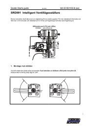
SRD991 Intelligent Positioner - FOXBORO ECKARDT
SRD991 Intelligent Positioner - FOXBORO ECKARDT
SRD991 Intelligent Positioner - FOXBORO ECKARDT

Create successful ePaper yourself
Turn your PDF publications into a flip-book with our unique Google optimized e-Paper software.
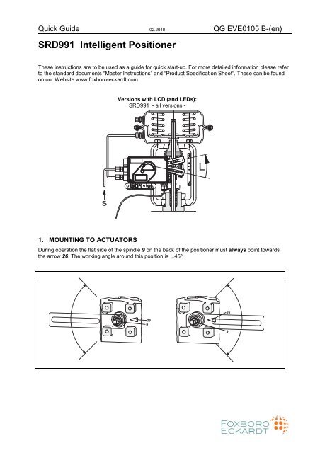
Quick Guide 02.2010 QG EVE0105 B-(en)<br />
<strong>SRD991</strong> <strong>Intelligent</strong> <strong>Positioner</strong><br />
These instructions are to be used as a guide for quick start-up. For more detailed information please refer<br />
to the standard documents “Master Instructions” and “Product Specification Sheet”. These can be found<br />
on our Website www.foxboro-eckardt.com<br />
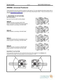
1. MOUNTING TO ACTUATORS<br />
Versions with LCD (and LEDs):<br />
<strong>SRD991</strong> - all versions -<br />
During operation the flat side of the spindle 9 on the back of the positioner must always point towards<br />
the arrow 26. The working angle around this position is ±45º.<br />
'<br />
$<br />
'<br />
$
2 <strong>SRD991</strong> QG EVE0105 B-(en)<br />
MOUNTING TO LINEAR ACTUATORS<br />
NAMUR Mounting - left hand -<br />
NAMUR Mounting - right hand -<br />
Feedback lever for linear actuators : Direct Mounting<br />
The carrier bolt B is in the slot of the feedback<br />
lever A and the compensating spring F touches<br />
the carrier bolt.<br />
* . )<br />
Carrier bolt B:<br />
1 threaded sleeve 2 Stud 3 coupling piece<br />
!<br />
� $<br />
MOUNTING TO ROTARY ACTUATORS<br />
• Do not tighten grub screw 4 against the thread<br />
of spindle 9 !<br />
• When in use the flat side of the spindle 9 must<br />
move ( 0 ↔ 100%) in front of the arrow 26.<br />
• When the product temperature rises, the drive<br />
shaft 1 increases in length. Therefore, the rotary<br />
adapter 3 must be mounted so that approx. 1<br />
mm (0.04 in.) of clearance results between the<br />
drive shaft 1 and the rotary adapter 3. This is<br />
achieved by placing an appropriate number of<br />
washers 5, on the feedback spindle 9, before<br />
attaching the rotary adapter. Two washers<br />
should result in a clearance of 1 mm.
QG EVE0105 B-(en) <strong>SRD991</strong> 3<br />
2. CONNECTIONS<br />
Actuator, left turning Actuator, right turning<br />
"<br />
'<br />
Check before mounting fittings and cable glands<br />
if threads are matching, otherwise housing can<br />
be damaged. The letter “G” on the housings<br />
marks that the pneumatic connections are in<br />
G1/4 (otherwise NPT).<br />
Ground<br />
Connect earth cable to screw #1 or screw #2 (in<br />
the electrical connection compartment).<br />
#<br />
!<br />
PNEUMATIC CONNECTIONS<br />
Air supply (s): 1.4 to 6 bar (but not more than the max. pressure of actuator), free of oil, dust and water !<br />
OO<br />
� �<br />
� �<br />
II<br />
Single acting, Direct mounting Single acting Double acting<br />
s supply y1, y2 pneumatic outputs (--) closed<br />
� �<br />
� �<br />
II<br />
OO<br />
'<br />
"<br />
#<br />
!<br />
� �<br />
/<br />
O O<br />
II<br />
OO
4 <strong>SRD991</strong> QG EVE0105 B-(en)<br />
3. ELECTRICAL CONNECTIONS<br />
The safety requirements of document EX EVE0001 as well as the requirements of PSS EVE0105 and MI<br />
EVE0105 for <strong>SRD991</strong> must be observed!<br />
3.1 Setpoint<br />
3.1.1 <strong>SRD991</strong>-xD (w/o communication)<br />
<strong>SRD991</strong>-xH (HART)<br />
<strong>SRD991</strong>-xE (FoxCom it1)<br />
3.2 Inductive Limit Switch<br />
3.2.1 <strong>SRD991</strong>-xxxT or U<br />
Two-wire proximity sensors, Acc. to DIN 19234 or NAMUR<br />
41+ 42- 51+ 52-<br />
3.1.2 <strong>SRD991</strong>-xF (FoxCom it2)<br />
3.1.3 <strong>SRD991</strong>-xP (PROFIBUS PA)<br />
<strong>SRD991</strong>-xQ (FIELDBUS FF)<br />
3.2.2 <strong>SRD991</strong>-xxxR<br />
41+ 43- 42 52<br />
Contact 2<br />
Contact 1<br />
Electric terminal C<br />
Supply voltage DC 10 to 30 V<br />
3.2.3 <strong>SRD991</strong>-xxxV<br />
Warning: For connection of micro switches please refer to MI (Master Instruction) and respect the<br />
safety requirements described in document EX EVE0001.<br />
3.3 Option Board<br />
Electric terminal C<br />
Switching amplifier with intrinsically<br />
safe control circuit<br />
Switching amplifier with intrinsically<br />
safe control circuit<br />
3.3.1 Two binary outputs (<strong>SRD991</strong>-xxP)<br />
Two-wire system, acc. to DIN 19234 or switched<br />
output.<br />
3.3.2 Two binary inputs (<strong>SRD991</strong>-xxB)<br />
Binary inputs with internal supply for connection<br />
of sensors or switches (switch closed for a<br />
normal operation!)<br />
3.3.3 Position feedback 4 to 20 mA and 1 Alarm<br />
(<strong>SRD991</strong>-xxQ ou <strong>SRD991</strong>-xxF)<br />
Analog output 4 to 20 mA and Binary output<br />
Two-wire system acc. to DIN 19234 or switched.<br />
3.3.4 Two binary in-/outputs (<strong>SRD991</strong>-xxE)<br />
Two-wire system acc. to DIN 19234 or switched<br />
in-/output.<br />
* For intrinsically safe circuits please refer to certificate / data label<br />
for max. operating voltages etc<br />
11+ 12-<br />
11+ 12-<br />
11 12<br />
81+ 82- 83+ 84-<br />
13+ 14- 15+ 16-<br />
81+ 82- 31+ 32-<br />
81+ 82-<br />
83+ 84-<br />
Input 4 to 20 mA<br />
Electric terminal A<br />
Electric terminal A<br />
Supply voltage DC 13 to 36 V *<br />
Electric terminal A<br />
Bus connection acc. to IEC 1158-2<br />
Supply voltage DC 9 to 32 V*<br />
Electric terminal B<br />
External power supply (e.g. intrinsically<br />
safe control circuit)<br />
External power supply (e.g. intrinsically<br />
safe control circuit)<br />
Electric terminal B<br />
Electric terminal B<br />
Analog output 4 to 20 mA,<br />
Two-wire system, supplied with extern<br />
power supply.<br />
External power supply (e.g. intrinsically<br />
safe control circuit)<br />
Electric terminal B<br />
Binary in-/output 4 to 20 mA,<br />
Two-wire system, supplied with ext.<br />
power supply<br />
Binary in-/output 4 to 20 mA,<br />
Two-wire system, supplied with ext.<br />
power supply
QG EVE0105 B-(en) <strong>SRD991</strong> 5<br />
4. START UP (Setting by means of local keys and LCD / LEDs)<br />
After mounting the positioner on the actuator, air and electrical input connected, you can start-up the<br />
SRD. The <strong>SRD991</strong> can be adjusted by means of a local key-pad and LCD / LED display.<br />
Attention: Do not touch behind the positioner housing while operating the keys! DANGER OF INJURIES!<br />
Description of display Push buttons<br />
Process variable<br />
87.5 %<br />
Valve position<br />
Process variable and diagnostics<br />
87.5 %<br />
Valve position<br />
Ctrl diff error<br />
(M)<br />
Enter or<br />
exit main<br />
menu<br />
(DOWN)<br />
Previous<br />
menu or<br />
Parameter<br />
(UP)<br />
Next menu<br />
or<br />
Parameter<br />
|-both simultaneously:-|<br />
At configuration: Main menu Enter / store<br />
SRD Main Menu<br />
1 Mounting<br />
2 Autostart<br />
3 Valve Action<br />
At configuration the selected item is displayed<br />
with dark background.<br />
Further menus with (UP) key.<br />
Configuration and operation with push buttons<br />
and LCD: and LED display:<br />
An already configurated device may show the<br />
An already configurated device is IN OPERATION<br />
following display:<br />
after power up, and all LEDs are off.<br />
87.5 %<br />
Valve position<br />
For configuration press (M) and main menu<br />
appears.<br />
For configuration press (M), and LEDs ‘M/F’ and<br />
‘1’ flash (= menu 1 is offered).<br />
If the SRD wasn’t configurated yet, the Main<br />
If the SRD wasn’t configurated yet, menu 1 is<br />
menu*) appears automatically after power-up:<br />
SRD Main Menu<br />
1 Mounting<br />
2 Autostart<br />
3 Valve Action<br />
offered automatically after power-up:<br />
In menu 1 you can select the type of mounting. In menu 1 you can select the type of mounting.<br />
*) On delivery the menu language in the display is English.<br />
The menu language can be changed over to another stored<br />
language. For this select 9.8.2 [german] or 9.8.3 [as ordered]<br />
and confirm with keys (UP)+(DOWN) (simultaneously).<br />
Leave menu by repeated pressing of (M) key.
6 <strong>SRD991</strong> QG EVE0105 B-(en)<br />
... and LCD: ... and LED display:<br />
Press keys (UP)+(DOWN) simultaneously to enter menu ‘Type of mounting’. Select the ‘Type of mounting’<br />
by pressing (UP) or (DOWN).<br />
1 Mounting<br />
1.1 Lin left<br />
1.2 Lin right<br />
1.3 rot cclockw<br />
(Further menus with (UP) key.)<br />
Press keys (UP)+(DOWN) simultaneously to confirm and save.<br />
The SRD moves back to menu level 1 and is in main menu again.<br />
SRD Main Menu<br />
1 Mounting<br />
2 Autostart<br />
3 Valve Action<br />
To enter next menu (= menu 2, AUTOSTART)<br />
press (UP) once.<br />
SRD Main Menu<br />
1 Mounting<br />
2 Autostart<br />
3 Valve Action<br />
Lin.actuator, left-hand<br />
mount.<br />
Lin.actuator, right-hand<br />
mount.<br />
Rotary actuator,<br />
opening ccw<br />
Rotary actuator,<br />
opening cw<br />
To enter next menu (= menu 2, AUTOSTART)<br />
press (UP) once, and the LEDs ‘M’ and ‘2’ flash.<br />
Press keys (UP)+(DOWN) simultaneously to enter menu ‘Autostart’. Select Full or Short autostart* by<br />
pressing (UP) or (DOWN).<br />
2 Autostart<br />
2.1 Endpoints<br />
2.2 Standard<br />
2.3 Enhanced<br />
Different Autostart options are available:<br />
2.1 Endpoints<br />
Determines only the mechanical stops of actuator/valve<br />
2.2 Standard<br />
Autostart recommended for standard application.<br />
2.3 Enhanced<br />
Enhanced Autostart. Optimized control behaviour compared to Standard Autostart.<br />
2.4 Smooth resp.<br />
Extended Autostart. Dampened control behaviour for e.g. smaller actuators.<br />
2.5 Fast resp.<br />
Extended Autostart. Undampened control behaviour for e.g. larger actuators.<br />
Press keys (UP)+(DOWN) simultaneously to confirm and to launch Autostart.<br />
Full autostart<br />
The automatic adaptation to the valve is composed of a sequence of steps, explained on the LCD or<br />
indicated by the LEDs.<br />
Following the last step the device is IN OPERATION.-
QG EVE0105 B-(en) <strong>SRD991</strong> 7<br />
Menustructure for <strong>SRD991</strong>/SRD960 with LCD<br />
SRD Main Menu<br />
Menu Factory Description<br />
configuration<br />
1 Mounting<br />
1.1 Lin left � Linear actuator, left-hand or direct mounting<br />
1.2 Lin right Linear actuator, right-hand mounting<br />
1.3 Rot cclockw Rotary actuator, opening counter-clockwise<br />
1.4 Rot clockw Rotary actuator, opening clockwise<br />
2 Autostart<br />
2.1 Endpoints Adaptation of the mechanical stops only<br />
2.2 Standard Autostart recommended for standard application<br />
2.3 Extended Extended Autostart, fast response with maybe overshoot<br />
2.4 Smooth resp. Extended Autostart, damped response to avoid overshoot<br />
2.5 Fast resp. Extended Autostart, very fast response with limited overshoot<br />
3 Valve Action<br />
3.1 SRD<br />
3.1.1 Direct � Valve opens with increasing setpoint value<br />
3.1.2 Reverse Valve closes with increasing setpoint value<br />
3.2 Feedback<br />
3.2.1 Direct � Increasing Current with increasing valve position<br />
3.2.2 Reverse Decreasing Current with increasing valve position<br />
4 Character<br />
4.1 Linear � Linear characteristic<br />
4.2 Eq Perc 1:50 Equal percentage characteristic 1:50<br />
4.3 Quick open Inverse equal percentage characteristic 1:50 (quick opening)<br />
4.4 Customer Custom characteristic<br />
5 Limits/alarms<br />
Not locally available with LED versions of communication FF and<br />
Profibus<br />
5.1 Lower limit 0 % Closing limit is set to input value<br />
5.2 Cutoff low 1 % 0%-tight sealing point is set to input value<br />
5.3 Cutoff high 100 % 100%-tight sealing point is set to input value<br />
5.4 Upper limit 100 % Opening limit is set to input value<br />
5.5 Splitr 0 % 4 mA Split range 0 %: input value corresponds to 0 %<br />
5.6 Splitr 100 % 20 mA Split range 100 %: input value corresponds to 100 %<br />
5.7 Lower Alarm -10 % Lower position alarm on output 1 is set to input value<br />
5.8 Upper Alarm 110 % Upper position alarm on output 2 is set to input value<br />
5.9 Valve 0% 4 mA Configuration of rated-stroke of 0% at 4 mA<br />
5.10 Valve 100% 20 mA Configuration of rated-stroke of 100% at 20 mA<br />
5.11 Stroke Range x° / 20mm Configuration of nominal travel<br />
5.12 Units SI Configuration of temperature and pressure unit SI or Anglo US<br />
6 Parameters<br />
6.1 Gain closing 15 P: Proportional gain for ‘close valve’<br />
6.2 Gain opening 2 P: Proportional gain for ‘open valve’<br />
6.3 Res time cl 7.5 I: Integration time for ‘close valve’<br />
6.4 Res time op 2.4 I: Integration time for ‘open valve’<br />
6.5 Rate lim cl 0.35 T63: Setting time for ‘close valve’<br />
6.6 Rate lim op 0.35 T63: Setting time for ‘open valve’<br />
6.7 Control gap 0.1 Permitted neutral zone for control difference<br />
7 Output Manual setting of IP-Module for testing of pneumatic output<br />
8 Setpoint Manual setting of valve position<br />
8.1 12.5% Steps Setpoint changes of 12.5% steps by using push buttons Up or Down<br />
8.2 1% Steps Setpoint changes of 1% steps by using push buttons Up or Down<br />
8.3 Do PST Start Partial Strok Test<br />
Continue on the next page...
8 <strong>SRD991</strong> QG EVE0105 B-(en)<br />
9 Workbench<br />
9.1 Reset Config Resetting of configuration to setting “ex factory”<br />
9.2 Calib. 4 mA Calibrate input current to 4 mA<br />
9.3 Calib. 20 mA Calibrate input current to 20 mA<br />
9.4 Calib. -45° Calibrate position measuring value to –45°<br />
9.5 Calib. +45° Calibrate position measuring value to +45°<br />
9.6 Reset all 1 Resetting of configuration and Calibration (!) to “ex factory” setting for<br />
single-acting output<br />
9.7 Reset all 2 Resetting of configuration and Calibration (!) to “ex factory” setting for<br />
double-acting output<br />
9.8 Go Online<br />
9.9 Menu Lang<br />
Setting position into mode Online<br />
9.9.1 English � Standard<br />
9.9.2 Deutsch<br />
Standard<br />
9.9.3 Français<br />
9.10 LCD orient<br />
Preselected / Freely Defiable<br />
9.10.1 Normal � Normal orientation of writing on LCD<br />
9.10.2 Flipped<br />
Reverse orientation of writing on LCD<br />
9.11 Cal. Feedbk Calibration of output current of position transmitter<br />
9.11.1 Cal 4mA Calibration of 0% at 4mA<br />
9.11.2 Cal. 20mA Calibration of 100% at 20mA<br />
10 - not available - for HART<br />
10 Profibus PA - Bus Address<br />
10.1 Address LSB Ratio from Dec. 0 / Hex 00 to Dec. 15 / Hex 0F<br />
10.2 Address MSB Ration from Dec. 0 / Hex 00 to Dec. 112 / Hex 70<br />
10.3 Address 126 Display of Bus Address from Dec. 1 to 127 (Hex 00 to 7F)<br />
10 FOUNDATION Fieldbus H1<br />
10.1 Simulate<br />
Disabled � Simulate disabled<br />
Enabled Simulate enabled<br />
10.2 Profile<br />
Link Master � Link Master active<br />
Basic Device Link Master de-activated<br />
Additional Documentation for this product:<br />
Technical Information of Attachment Kits for <strong>Positioner</strong>s<br />
TI EVE0011 A Overview of Attachment Kits of all positioners on actuators/valves of different<br />
manufacturers<br />
Quick Guide<br />
QG EVE0105 A Extract of Master Instruction for an easy to use, easy understandable and fast<br />
start-up. This document highlights the most important.<br />
Master Instructions:<br />
MI EVE0105 E <strong>SRD991</strong> -all versions-<br />
Technical Information for Fieldbus-Communication:<br />
TI EVE0105 P <strong>SRD991</strong>/960 -PROFIBUS-PA<br />
TI EVE0105 Q <strong>SRD991</strong>/960 -FOUNDATION Fieldbus H1<br />
Master Instruction for HART-Communication:<br />
MI EVE0105 B HART with Hand-Held Terminal<br />
<strong>FOXBORO</strong> <strong>ECKARDT</strong> GmbH <strong>ECKARDT</strong> S.A.S.<br />
Pragstrasse 82 20 rue de la Marne<br />
D-70376 Stuttgart F-68360 Soultz<br />
Germany France<br />
Tel. + 49(0)711 502-0 Tel. + 33 (0)3 89 62 15 30<br />
Fax + 49(0)711 502-597 Fax + 33 (0)3 89 62 14 85<br />
http://www.foxboro-eckardt.de http://www.foxboro-eckardt.com