244LVP Intelligent Buoyancy Transmitter for ... - Foxboro Eckardt
244LVP Intelligent Buoyancy Transmitter for ... - Foxboro Eckardt
244LVP Intelligent Buoyancy Transmitter for ... - Foxboro Eckardt

Create successful ePaper yourself
Turn your PDF publications into a flip-book with our unique Google optimized e-Paper software.
Master Instruction 02.2010 MI EML1710A-(en)<br />
<strong>244LVP</strong> <strong>Intelligent</strong> <strong>Buoyancy</strong> <strong>Transmitter</strong><br />
<strong>for</strong> Liquid Level, Interface and Density<br />
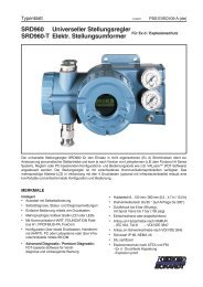
The intelligent transmitter <strong>244LVP</strong> is designed to per<strong>for</strong>m continuous measurements <strong>for</strong> liquid level, interface or density<br />
of liquids in the process of all industrial applications. The measurement is based on the proven Archimedes buoyancy<br />
principle and thus extremely robust and durable. Measuring values can be transferred analog and digital. Digital<br />
communication facilitates complete operation and configuration via PC or control system. The <strong>244LVP</strong> measures<br />
with consistent reliability and high precision. For installations in contact with explosive atmospheres up to Zone 0, certificates<br />
are available. The <strong>244LVP</strong> combines the abundant experience of FOXBORO ECKARDT with most advanced<br />
digital technology.<br />
FEATURES<br />
• Communication HART (4-20 mA)<br />
• Conventional operation with local keys<br />
• Easy adaptation to the measuring point<br />
without calibration at the workshop<br />
• Backdocumentation of measuring point<br />
• Configurable safety value<br />
• Software lock against unauthorized operation<br />
• Simulation of analog output <strong>for</strong> loop-check<br />
Repair and maintenance must be carried out by qualified personnel!<br />
• Local display in %, mA or physical units<br />
• Signal noise suppression by Smart Smoothing<br />
• Continuous self-diagnostics<br />
• Linear or customized characteristic<br />
• Process temperature from –50 °C to +150 °C<br />
• Static pressure up to PN 40<br />
• Micro sintermetal sensor technology
2 <strong>244LVP</strong> MI EML1710 A-(en)<br />
CONTENTS<br />
CHP. CONTENTS PAGE<br />
1 DESIGN 3<br />
2 METHOD OF OPERATION 3<br />
2.1 Measuring principle 4<br />
2.2 Block diagram <strong>for</strong> HART Communication 5<br />
2.3 Explanations to Black diagram 5<br />
3 IDENTIFICATION 8<br />
3.1 <strong>Transmitter</strong> nameplate 8<br />
3.2 Tag No. label 8<br />
3.3 Amplifier nameplate 8<br />
3.4 Displacer and pressure rating 8<br />
4 MOUNTING 9<br />
4.1 Mounting on top of the vessel 9<br />
4.2 Mounting on the side of the vessel 9<br />
4.3 <strong>Transmitter</strong> mounting 10<br />
4.4 Displacer 204DE 11<br />
5 ELECTRICAL CONNECTION 12<br />
5.1 Signal wire connection 12<br />
6 COMMISSIONING 13<br />
7 DECOMMISSIONING 13<br />
8 CALIBRATION OF TRANSMITTER 14<br />
8.1 Calibration via local keys 14<br />
Setup of lower and upper range value 15<br />
8.2 Hardware write protection 16<br />
8.3 Calibration via Display Keys 17<br />
8.3.1 Menu node “Display measurement value” 18<br />
8.3.2 Menu node “MAINT” 19<br />
8.3.3 Menu node “SPECIAL” 20<br />
8.3.4 Error messages 23<br />
8.3.5 Warning messages 23<br />
8.3.6 Monitoring of time 23<br />
9 SAFETY REQUIREMENTS 24<br />
9.1 General requirements 24<br />
9.2 Explosion protection 24<br />
10 DIMENSIONS 25<br />
11 DIMENSIONING OF DISPLACER 26<br />
12 SUPPLY OF TRANSMITTER 28<br />
12.1 General 28<br />
12.2 Overview of application types 28<br />
12.2.1 Supply via power supply unit 28<br />
12.2.2 Direct supply 28<br />
12.2.3 Communication 29<br />
12.2.4 Operating via I/A-System 29<br />
12.2.5 Intrinsically-safe application 29<br />
Further documentation:<br />
Master Instruction<br />
MI EML0610 B-(en) / MI EML1610 B-(en)<br />
144LD / 144LVD<br />
<strong>Intelligent</strong> <strong>Buoyancy</strong> <strong>Transmitter</strong>s<br />
Communication with HART Protocol<br />
Master Instruction<br />
MI EMO0110 A-(en)<br />
HT991 Universal Hand terminal <strong>for</strong> HART Devices<br />
Master Instruction<br />
MI EMO0120 A-(en)<br />
ABO991 Display and User Interface <strong>for</strong> HART devices<br />
WPP991 Write Protection Program<br />
Master Instruction<br />
MI EML0610 C-(en) / MI EML1610 C-(en)<br />
144LD / 144LVD<br />
<strong>Intelligent</strong> <strong>Buoyancy</strong> <strong>Transmitter</strong>s<br />
Communication with FOXCOM Protocol<br />
HHT Instruction Book 3372<br />
I/A Series Hand Held Terminal<br />
PC10 Instruction Book 3466<br />
<strong>Intelligent</strong> <strong>Transmitter</strong> Configurator
MI EML1710 A-(en) <strong>244LVP</strong> 3<br />
1 DESIGN<br />
The transmitter is based on a modified pressure measuring<br />
cell. The sensor is a flexure beam, which is mechanically<br />
linked to the measuring diaphragm,<br />
1 Amplifier<br />
2 Cable gland (as ordered)<br />
5 Process connection flange<br />
2 METHOD OF OPERATION<br />
The buoyancy <strong>for</strong>ce of the displacer acts directly on the<br />
flexure beam. Four thin film metal resistors are sputtered<br />
onto the sensor element, which change their resistance in<br />
the ratio of the tensile or pressure tension.<br />
These four thin film metal resistors are connected as a<br />
so the measuring cell also can be used <strong>for</strong> <strong>for</strong>ce measurement.<br />
The static pressure in vessel does not influence the<br />
measurement.<br />
6 Sensor<br />
7 Suspension fixture<br />
8 Displacer<br />
Wheatstone full bridge supplied from amplifier. The voltage<br />
at the diagonal bridge section which is proportional to the<br />
effective weight is fed to the electronic amplifier as an input<br />
signal.<br />
See also chap 2.2 Block diagram.<br />
#<br />
$<br />
%<br />
&
4 <strong>244LVP</strong> MI EML1710 A-(en)<br />
2.1 Measuring principle<br />
(see VDI/VDE Guideline 3519, sheet 1)<br />
Any body immersed into a liquid is subject to Archimedian<br />
buoyancy <strong>for</strong>ce which depends on the liquid density. This is<br />
exploited to determine liquid level, density and interface<br />
level by suspending a displacer with constant cylindric<br />
shape into a liquid.<br />
The following applies in general to the buoyancy<br />
<strong>for</strong>ce acting on the displacer:<br />
FA =Vx ⋅ρ1 ⋅ g +(V - Vx ) ⋅ρ2 ⋅ g<br />
FA <strong>Buoyancy</strong> <strong>for</strong>ce<br />
V Volume of displacer<br />
Vx Volume of medium displaced by measuring body<br />
with density ρ1<br />
ρ1 Average density of heavier medium<br />
ρ2 Average density of lighter medium<br />
g Local acceleration due to gravity<br />
FG Displacer body weight <strong>for</strong>ce<br />
The <strong>for</strong>ce acting on the transmitter is inversely<br />
proportional to liquid level changes.<br />
F A<br />
Displacer characteristic<br />
within the measured medium<br />
F A(0%) = F G<br />
Measuring range<br />
F A (100 %)<br />
Liquid level<br />
Changes in buoyancy <strong>for</strong>ces are proportional to liquid level<br />
changes and are converted to a measuring signal.<br />
The displacer is fully immersed <strong>for</strong> density and interface<br />
level detection. It is important that the position of the<br />
displacer changes as little as possible over the measuring<br />
range.<br />
100 %<br />
0%<br />
�<br />
2<br />
�<br />
1<br />
L<br />
F A<br />
F<br />
G<br />
V<br />
V x
MI EML1710 A-(en) <strong>244LVP</strong> 5<br />
2.2 Block diagram with HART<br />
5 A � I � H<br />
� E� A<br />
. HA G K A � ? O<br />
. E�JA H<br />
� E� A = HE� = JE� �<br />
6 A � F A H= JK HA<br />
? � � F A � I = JE� �<br />
� A = I K HA @<br />
8 = �K A<br />
5 A JJE� C I<br />
5 A � I � H<br />
) @ �K I J<br />
5 � = HJ<br />
5 � � � JD E� C<br />
# �$ 0 � , = � F E� C JE� A . E� C A HF HE� J , = J= 5 F = �<br />
6 � �A H= � ? A * = � @<br />
�<br />
� A H�<br />
6 E� A<br />
�<br />
�<br />
+ D = H? JA HEI JE?<br />
BK � ? JE� �<br />
� E� A = H<br />
5 G K = HA 4 � � J @<br />
+ K I J� �<br />
� K JF K J<br />
+ D = H? JA HEI JE?<br />
� E� A = H<br />
5 G K = HA 4 � � J @<br />
. E�JA H<br />
+ K I J� �<br />
+ = �E> H= JE� �<br />
� � M A H 6 HE� 2 � E� J<br />
7 F F A H 6 HE� 2 � E� J<br />
� �<br />
� � M + K J<br />
� � M 3 K = � JEJO<br />
5 K F F HA I I E� �<br />
2.3 Explanations to Block diagrams<br />
� � M EJD<br />
� K JF K J + D = H= ? JA HEI JE?<br />
5 G K = HA 4 � � J @<br />
Sensor<br />
The <strong>for</strong>ce sensor is a Wheatstone bridge of four metal strain<br />
gauge elements and a Ni100 resistor <strong>for</strong> temperature measurement.<br />
For calibration the sensor is loaded with weights,<br />
in order to determine the characteristic of the sensor.<br />
The Lower Range Value is determined by a small buoyancy<br />
<strong>for</strong>ce (high weight), Upper Range Value by a larger buoyancy<br />
<strong>for</strong>ce (lower weight).<br />
Linearization and Temperature compensation<br />
of Sensor characteristic<br />
The sensor signal is linearized and temperature-compensated<br />
by the included sensor temperature. Linearization<br />
takes place via the so-called fingerprint data, which are<br />
determined during the production <strong>for</strong> each sensor. In factory<br />
the fingerprint data are loaded into the amplifier.<br />
Line Frequency Suppression Filter<br />
There is the selection to filter the noise signal 50 Hz or 60 Hz.<br />
� A = I K HA @ 8 �<br />
7 � EJ<br />
+ � � L A HJE� C<br />
J� � )<br />
7 F F A H<br />
� A = I K HA @<br />
8 = �K A<br />
� � M A H<br />
� A = I K HA @<br />
8 = �K A<br />
� A = I K HA @<br />
4 = � C A<br />
5 A JJE� C I<br />
� � M A H 4 = � C A 8 �<br />
7 F F A H 4 = � C A 8 �<br />
4 A F �= ? A � A � J<br />
8 = �K A<br />
4 A F �� 8 = �K A<br />
! �& ��� ! � )<br />
� E� A = H E� = JE� �<br />
� = N � 9 A EC D J<br />
� A H� 2 � E� J<br />
7 � EJ<br />
E� 2 A H? A � J<br />
2 8<br />
6 A � F A H = JK H A + � � F A � I = JE� �<br />
� K �JE�, H� F 0 ) 4 6<br />
) � = �� C �@ EC EJ= � . � N + � �<br />
� . = ? J� HO I A JJE� C I<br />
� � 9 EJD 2 + + = �E> H= JE� �<br />
�" � + � & � +<br />
� 7 6 �<br />
2 7 6<br />
7 F F A H<br />
� A = I K HA @<br />
8 = �K A<br />
� � M A H<br />
� A = I K HA @<br />
8 = �K A
6 <strong>244LVP</strong> MI EML1710 A-(en)<br />
Smart Smoothing<br />
In factory the Smart Smoothing Band is set to 0.15 % of<br />
sensor range. The Integration Time of the average value is<br />
setto10sec.<br />
� A = I K HA @ 8 = �K A<br />
� A = I K HA @ 8 = �K A<br />
5 F = �<br />
� A H�<br />
I J= JE?<br />
M EJD � K J<br />
5 � = HJ 5 � � � JD E� C<br />
@ O � = � E?<br />
� � M A H<br />
4 = � C A 8 = �K A<br />
M EJD<br />
5 � = HJ 5 � � � JD E� C<br />
J� I A ?<br />
5 � = HJ<br />
5 � � � JD E� C<br />
* = � @ M E@ JD<br />
J�I A ?<br />
J�I A ?<br />
Sensor Adjustment<br />
Zero and span of <strong>for</strong>ce sensor are adjusted in factory.<br />
It is possible to calibrate Zero (situation alignment) with the<br />
external 0% key (see 8.3).<br />
� #<br />
7 F F A H<br />
4 = � C A 8 = �K A<br />
Custom Calibration<br />
The user has the possibility with this function of calibrating<br />
the trans<strong>for</strong>mer according to his conceptions. By giving of a<br />
lower and upper measured value the transfer characteristic<br />
is again adjusted. This custom calibration can be reset to<br />
factory calibration.<br />
� K JF K J<br />
+ K I J� �<br />
+ = �E> H = JE� �<br />
7 F F A H<br />
6 HE� F � E� J<br />
1� B�K A � ? A � B � � M A H<br />
+ = �E> H= JE� � 2 � E� J<br />
� � M A H<br />
6 HE� F � E� J<br />
� A H�<br />
F � E� J<br />
5 F = �<br />
� � M A H<br />
5 A � I � H 8 = �K A<br />
1� B�K A � ? A � B 7 F F A H<br />
+ = �E> H= JE� � 2 � E� J<br />
7 F F A H<br />
5 A � I � H 8 = �K A<br />
� A H� 5 F = �<br />
5 A � I � H 6 HE�<br />
2 = I I M � H@<br />
F H� JA ? JA @<br />
We only recommend a custom calibration with either lower<br />
plus upper calibration or an exclusive upper calibration.<br />
Transfer function / Characteristic<br />
The characteristics are available linear, root-extracted and<br />
customized. With "customized" there are 32 x/y- values<br />
available. Standard with Level is “linear”.
MI EML1710 A-(en) <strong>244LVP</strong> 7<br />
Measured Value Setting<br />
The user can define measured value and unit.<br />
� A M<br />
8 = �K A<br />
A �C � �<br />
7 F F A H<br />
4 = � C A 8 = �K A<br />
A �C � �# �<br />
� � M A H<br />
4 = � C A 8 = �K A<br />
A �C � �# �<br />
7 F F A H<br />
� K JF K J<br />
L = �K A<br />
A � C �<br />
� � M A H<br />
� K JF K J<br />
L = �K A<br />
A � C �<br />
� � M A H 4 = � C A 8 = �K A<br />
A �C � �# �<br />
' �$ ! �<br />
Setting of Range<br />
The measuring range is the range between Lower Range<br />
Value and Upper Range Value. Lower Range Value is the<br />
weight of the displacer. Lower Range Value without<br />
elevation is 0. With elevation, the value of elevation has to<br />
be entered.<br />
� A = I K HA @ L = �K A<br />
Setting of Output value<br />
The output value is the measured value between Lower<br />
Range Value and Upper Range Value. Value and unit are<br />
freely selectable. The replacement value affects the output.<br />
7 F F A H 4 = � C A 8 = �K A<br />
A �C � �# �<br />
Low Quantity Suppression<br />
Setting On or Off <strong>for</strong> low quantity suppression with rootextracted<br />
output. With Level, low quantity suppression is<br />
always 0.<br />
Output characteristic<br />
The Output characteristic can be root- extracted.<br />
Replacement / Substitute Value<br />
In case of error output holds last value or gives a configurable<br />
Replacement value.<br />
If the error does not exist any longer, then "last value" and/<br />
or replacement value is taken back (automatic or manuell).<br />
Multi-drop<br />
With PC20 or a Hand Held Terminal it is possible to switch<br />
HART-Amplifier between “analog” and “Multi-drop”.<br />
With HART-mode “Multi-drop” the output has a digital signal,<br />
the measured value is modulated toa4mADCsignal.<br />
PC20 Software enables to simulate the measured value<br />
and to write output values directly to the output.<br />
Filter<br />
The output signal is damped; damping time ist setable from<br />
0 to 32 sec (90%).
8 <strong>244LVP</strong> MI EML1710 A-(en)<br />
3 IDENTIFICATION<br />
!<br />
The transmitter is identified with three labels. The transmitter<br />
nameplate 3.1 shows the Model Code of the transmitter,<br />
which clearly describes the device. The certificate<br />
data and the serial No. are entered on the amplifier nameplate<br />
3.3 . The TAG No. label 3.2 with the Tag No. is<br />
located underneath (optional). Data about the permissible<br />
static pressure and the displacer are documented on the<br />
data label 3.4 on the process connection flange.<br />
3.1 <strong>Transmitter</strong> nameplate<br />
(Example)<br />
Device specification, Model Code<br />
� � , - �<br />
8 - 4 , 4 � � / - 4<br />
, 15 2 � ) + - 4<br />
� - 5 5 7 � . � 4 � - 4 � 6 4 ) � 5 � 16 6 - 4<br />
" " � 8 2 � 5 5 & + * � 0 � � �<br />
- + - 2 � 4 - 8 �� H� �<br />
ID No. <strong>for</strong> special version<br />
3.2 Tag No. label<br />
(Example)<br />
Directly fixed or attached<br />
� � � / -<br />
� - � / 6 0<br />
8 � � 7 � - �<br />
8 � � 7 � -<br />
/ - 9 1+ 0 6<br />
9 - 1/ 0 6<br />
LID 09/16<br />
! "<br />
� ! & "<br />
�<br />
�<br />
� �<br />
? � !<br />
�<br />
6 �<br />
5 9<br />
2 �<br />
, 4 7 + � �6 - � 2 �<br />
* - 4 - 1+ 0<br />
2 4 - 5 5 7 4 - �6 - � 2 �<br />
4 ) 6 1� / 5<br />
3.3 Amplifier nameplate<br />
(Examples)<br />
"<br />
� ! � #<br />
� � � � 7 � 1� ) 6 1� �<br />
" ��� � )<br />
0 1� . 5 - � - 4 / 1-<br />
2 � 9 - 4 5 7 2 2 � ;<br />
Without explosion protection<br />
With explosion protection acc. to ATEX<br />
With explosion protection acc. to FM/CSA<br />
3.4 Displacer and pressure rating<br />
(Example)<br />
When ordered with a displacer, the transmitter is supplied<br />
with an application nameplate mounted at the circumference<br />
of the process connection flange.<br />
" ! #<br />
�<br />
8 - 4 5 6 � 4 � - 4 � ) � 2 � 1. 1- 4<br />
� +<br />
> = H<br />
5 - 4 �� � �<br />
� = @ A E� / A H� = � O > O<br />
. � : * � 4 � - + � ) 4 , 6 / � > 0<br />
, � % ! % $ 5 6 7 6 6 / ) 4 6<br />
* ) 7 � ) 0 4<br />
; - ) 4<br />
1� 0 ) � 6<br />
8 � � 7 � -<br />
9 - 4 � 5 6 � . .<br />
� ) 6 - 4 1) �<br />
) 7 5 / ) � / � � 7 6 2 7 6<br />
Displacer specification Temperature and Nominal pressure Flange material<br />
per order pressure ratings<br />
maximum static pressure at 120 °C<br />
- * -<br />
�<br />
- * -<br />
�<br />
0 ) 4 6<br />
� � � � 7 � 1� ) 6 1� �<br />
" ��� � )<br />
0 ) 4 6<br />
2 6 * � H�<br />
. � : + � � 16<br />
. � : + � � 16<br />
8 - 4 5 6 � 4 � - 4 � ) � 2 � 1. 1- 4<br />
5 - 4 �� � �<br />
� !<br />
2 4 � . 1* 7 5 = ? ? � . 15 + �<br />
. . . 1- � , * 7 5 0<br />
2 4 � . 1* 7 5 = ? ? � . 15 + �<br />
. . . 1- � , * 7 5 0<br />
6 ; 2 -<br />
2 E 7 E 1E + E � E 6 = � ><br />
�<br />
�<br />
. � : + � � 16<br />
. � : + � � 16<br />
) 6 - :<br />
- � - + 6 4 1+ ) � 6 4 ) � 5 � 16 6 - 4<br />
15 . � 4 + � 1� , 18 � / 4 2 5 ) � * � + , � + � 11� , 18 �<br />
/ 4 2 5 - � . / � + � 111� 0 ) � ) 4 , � 7 5 � � + ) 6 1� � 5<br />
5 - - , 4 ) 9 �<br />
9 ) 4 � 1� / � 5 7 * 5 6 16 7 6 1� � � . + � � 2 � � - � 6 5<br />
� ) ; 1� 2 ) 14 1� 6 4 1� 5 1+ 5 ) . - 6 ; �<br />
I EA D A * A JHEA > I = � �A EJK � C<br />
I A A 1� I JHK ? JE� � � = � K = �<br />
� = @ A E� / A H� = � O > O<br />
. � : * � 4 � - + � ) 4 , 6 / � > 0<br />
, � % ! % $ 5 6 7 6 6 / ) 4 6<br />
5 - 4 � � � � � 7 6 2 7 6<br />
� )<br />
- N E=<br />
"<br />
� 16 - 4<br />
� " " "<br />
) 2 2 4 � 8 - ,<br />
5 7 16 ) * � - . � 4 + � 1� , 18 � / 2 ) � * � + � , � 5 7 16 ) * � - . � 4 + � 11� , 18 � / 2 . / �<br />
5 7 16 ) * � - . � 4 + � 111� 9 ) 4 � 1� / � , � � � 6 , 15 + � � � - + 6 - 3 7 12 � - � 6 7 � � - 5 5<br />
2 � 9 - 4 0 ) 5 * - - � 5 9 16 + 0 - , � . . � 4 6 0 - ) 4 - ) 15 � � � 9 � 6 � * - � � � �<br />
0 ) � ) 4 , � 7 5 � 9 ) 4 � 1� / �- : 2 � � 5 1� � 0 ) � ) 4 , �5 7 * 5 6 16 7 6 1� � � . + � � 2 � �<br />
� - � 6 5 � ) ; 1� 2 ) 14 5 7 16 ) * 1� 16 ; . � 4 + � ) 5 5 � , 18 15 1� � � 6 ; 2 - " :<br />
+ 5 ) = � @ . � � 6 " ) ( " � + � ) : ) � * � + 5 ) � 6 ! + ( & # � + � 6 " ( $ � + � ) : ) � *<br />
"<br />
. � � 6 " (<br />
, + � !<br />
& # � + � ) : ) � *<br />
8
MI EML1710 A-(en) <strong>244LVP</strong> 9<br />
4 MOUNTING<br />
The transmitter is directly built onto the vessel or alternatively<br />
on a side-mounted displacer chamber 204DC.<br />
During installation, the permissible static pressure and the<br />
ambient temperature range must be observed<br />
(see chapter 3, “Identification”).<br />
Note:<br />
Proceed with caution during all installation work.<br />
Do not damage the diaphragm!<br />
Do not drop the suspended displacer!<br />
Avoid jointing!<br />
4.1 Mounting on top of the vessel<br />
" , -<br />
<strong>Transmitter</strong> at Connection flange<br />
Displacer 204DE in protection cage / tube<br />
If the vessel contains a turbulent liquid a protection cage /<br />
tube should be used. If a tube is used, make sure there is a<br />
venting hole above maximum process level. Between the<br />
protection cage / tube and the displacer must be a gap of at<br />
least 5 ... 10 mm.<br />
4.2 Mounting on the side of the vessel<br />
" , -<br />
" , +<br />
<strong>Transmitter</strong> and Shut-off device<br />
Displacer 204DE in Displacer Chamber 204DC<br />
When used in Zone 0, fittings resistant to flame penetration<br />
must be used.<br />
If the chamber has not already been mounted by the<br />
customer, it must be mounted to the vessel with suitable<br />
bolts and seals (not included in the scope of delivery). Be<br />
sure that the displacer chamber is exactly vertical.<br />
Between the chamber and the displacer must be a gap of at<br />
least 5 ... 10 mm.<br />
NOTE:<br />
For explosion-proof devices or devices with certification as<br />
overfill protection according to WHG, the remarks in the<br />
product specifications PSS EML1710 A and in certificates<br />
or approvals must be observed.
10 <strong>244LVP</strong> MI EML1710 A-(en)<br />
4.3 <strong>Transmitter</strong> mounting<br />
Ensure correct matching of transmitter and displacer while<br />
mounting. Each transmitter is calibrated <strong>for</strong> use with the<br />
respective displacer according to ordering data in the<br />
factory. Each displacer is marked with the TAG No. or, if not<br />
known, with the last three digits of the serial number of the<br />
respective transmitter. The corresponding displacer data<br />
(length, volume and weight) are specified on the adjustment<br />
data labels mounted on the process connection flange. See<br />
also chapter 3 ”Identification”.<br />
Fit installation seal 139 on the flange 140 on the<br />
container side. Always use a new seal. The seal must be<br />
suitable <strong>for</strong> the flange size and the measured medium.<br />
Attach displacer to suspension fixture 154 of transmitter.<br />
Long displacers can be placed in the container ahead of<br />
time. Multi-section displacers see chapter 4.4.<br />
" !<br />
"<br />
# "<br />
! '<br />
"<br />
" !<br />
)<br />
*<br />
+<br />
Carefully place transmitter and displacer onto the container<br />
flange 140 . Make sure the seal is accurately positioned.<br />
Avoid impacts and jolting under all circumstances.<br />
Tighten studs 142 and nuts 143 . Apply recommended<br />
torque (see tables below).<br />
For com<strong>for</strong>table reading the LCD, the upper section can be<br />
turned around nearly 360 degrees. For this loosen the<br />
screws A and B (but do not remove!)(SW5) and turn upper<br />
section into desired direction. Tighten again screws A and<br />
B.<br />
The high screw B is stop <strong>for</strong> screw C. Thus it to prevent<br />
endlessly turning round of upper section that could damage<br />
the inside wires.<br />
Rated<br />
pressure<br />
Threaded bolt at rated diameter<br />
PN Class DN 80 / 3" DN 100 / 4" DN 70<br />
16 150 M16 M16 –<br />
40 300 M16 / M20 M20 –<br />
Recommended torque<br />
(pre-stressed to 70 % of minimum yield point at 20 °C)<br />
Studs Mat. M16 M20 M24 M27 M30 M33 M36 M39<br />
Tightening<br />
torque<br />
[Nm]<br />
A2 *) 80 150 140 210 290 330 420 560<br />
GA 115 220 370 545 770 1000 1300 1750<br />
*) Yield point <strong>for</strong><br />
material A2<br />
(acc. to DIN 267)<br />
≤ M20 450 N/mm²<br />
M24 to M30 250 N/mm²<br />
> M30 210 N/mm²
MI EML1710 A-(en) <strong>244LVP</strong> 11<br />
4.4 Displacer 204DE<br />
Important<br />
Displacer and transmitter must be matched properly during<br />
installation (see chapter 4.3).<br />
Pressure Rating<br />
The displacer must be designed <strong>for</strong> the pressure rating of<br />
the vessel - however, at least to the operating pressure -<br />
and ordered accordingly. Here the maximum possible<br />
temperature must be taken into consideration.<br />
Displacers made of PTFE are made from solid material,<br />
and are, there<strong>for</strong>e, suitable <strong>for</strong> all pressures<br />
(see Product Specifications PSS EML1710 A).<br />
Jointed displacer elements<br />
Displacers of length over 3 meters are jointed (multisection)<br />
displacer elements. The displacer elements are<br />
screwed together and secured with the wire clip 151 to<br />
avoid bending or damage during insertion into the vessel.<br />
The elements of displacers with Ø < 13 mm are not<br />
screwed together; they are secured with hook and eyelet<br />
152 . Additional securing is not necessary 1) .<br />
diameter diameter<br />
>13mm
12 <strong>244LVP</strong> MI EML1710 A-(en)<br />
5 ELECTRICAL CONNECTION<br />
5.1 Signal wire connection<br />
At both sides of the amplifier housing is a threaded hole<br />
(threads as ordered) <strong>for</strong> cable gland 38 or cover screw 39 .<br />
The used cable glands have to con<strong>for</strong>m to any Ex requirements.<br />
User assumes responsibility.<br />
Actions:<br />
– Remove cover lock 24 (if provided) and unscrew top<br />
housing cover 22 .<br />
– Lead cable through screwed gland and connect with<br />
terminals 45, 46 and 47 .<br />
– If necessary connect external ground 48 .<br />
– Screw top housing cover 22 and install cover<br />
lock 24 (if provided).<br />
Note<br />
For explosion-proof devices follow reference <strong>for</strong> cable gland<br />
and cover screw in document<br />
"Safety Operating Instructions 140 Series"<br />
! '<br />
" # " % " $<br />
22 Top housing cover<br />
24 Cover lock<br />
38 Cable gland <strong>for</strong> cable with Ø 6 to 12 mm<br />
39 Cover screw<br />
48 External ground<br />
50 Overvoltage protection (if present)<br />
45 Connection terminal 1) +<br />
46 Connection terminal 1) –<br />
47 Ground terminal 1)<br />
1) wire cross section max. 2.5 mm²<br />
"<br />
! &<br />
" &
MI EML1710 A-(en) <strong>244LVP</strong> 13<br />
6 COMMISSIONING<br />
Principally, installation and safety regulations have to be<br />
checked prior to commissioning.<br />
After correct installation, signal wire connection and product<br />
connection, the transmitter is ready <strong>for</strong> operation. If<br />
necessary the configuration of lower range value, upper<br />
range value and damping has to be checked.<br />
Protect the environment; do not allow measuring substance<br />
to escape. Catch and dispose them properly.<br />
Checking the settings<br />
Checking the lower range value <strong>for</strong> level measurement<br />
For level measurements, the weight FG of the displacer is<br />
equal to the weight <strong>for</strong>ce F0 <strong>for</strong> the lower range value<br />
(LRV). An exception is the measuring range with elevation.<br />
The lower range value (LRV) can be checked with a<br />
free-hanging displacer and a completely empty vessel.<br />
Checking the lower range value <strong>for</strong> measuring range<br />
with elevation<br />
The lower range value (LRV) F0 can only be checked by<br />
specifying the vessel level corresponding to F0 or by<br />
specifying the weight <strong>for</strong> F0 (workshop task).<br />
Checking the lower range value <strong>for</strong> interface and<br />
density<br />
The lower range value (LRV) F0 canbecheckedwiththe<br />
following methods:<br />
– Displacer is completely immersed in the liquid with the<br />
lower density<br />
– by specifying the weight <strong>for</strong>ce <strong>for</strong> F0 with weights (in the<br />
workshop)<br />
Upper range value<br />
The upper range value (URV) F100 canbecheckedwiththe<br />
following methods:<br />
– by producing the corresponding level, interface or<br />
density, provided the specified operating densities are<br />
correct.<br />
– by specifying the weight <strong>for</strong>ce <strong>for</strong> F0 with weights (in the<br />
workshop).<br />
Damping<br />
Damping of 8 sec is set at factory. If necessary, this value<br />
can be checked on devices with an LCD indicator and<br />
changed locally.<br />
Correction of lower range value, upper range value,<br />
damping, see chapter 9, “Calibration of <strong>Transmitter</strong>”.<br />
7 DECOMMISSIONING<br />
Prior to decommissioning take precautions to avoid<br />
disturbances:<br />
– Observe Ex. protection.<br />
– Switch off power supply.<br />
– Caution with hazardous process media!<br />
With toxic or harmful process media, observe relevant<br />
safety regulations.<br />
Be<strong>for</strong>e dismantling the transmitter, the procedure below<br />
should be followed:<br />
– Depressurize vessel or displacer chamber.<br />
– Drain off measuring medium in displacer chamber.<br />
– Protect the environment; do not allow measuring<br />
substance to escape. Catch and dispose them properly.<br />
The procedure <strong>for</strong> dismantling the transmitter is the reverse<br />
of that described <strong>for</strong> mounting.<br />
Note:<br />
Proceed with caution during all installation work.<br />
Do not damage the diaphragm!<br />
Do not drop the suspended displacer!<br />
Avoid jointing!
14 <strong>244LVP</strong> MI EML1710 A-(en)<br />
8 CALIBRATION OF TRANSMITTER<br />
Zero, lower range value, upper range value and damping of<br />
the transmitter are set by manufacturer as specified in the<br />
order.<br />
There<strong>for</strong>e, calibration at start-up is not necessary.<br />
In case the order does not include this data, the transmitter<br />
is supplied as follows:<br />
displacer weight <strong>for</strong>ce = 1.500 kg<br />
buoyancy = 5.884 N (0.600 kg)<br />
indication = %<br />
damping = 8 sec (63 % time)<br />
Operating data and displacer data are stored in the<br />
transmitter according to the order.<br />
Calibration becomes necessary if this data deviates from<br />
the values stored.<br />
The transmitter is designed <strong>for</strong> a displacer weight <strong>for</strong>ce of<br />
max. 2.5 kg 1) and a buoyancy <strong>for</strong>ce of 2 N to 20 N. The<br />
lower range value F0 must be within the range 2 kg to 2.5<br />
kg. 1)<br />
Calibration of devices via operating push buttons<br />
Calibration can be done by means of the push buttons at<br />
the transmitter if the amplifier housing has<br />
• either external push buttons, see Chap. 8.1<br />
”Calibration via local keys”<br />
• or display with internal push buttons, see Chap. 8.3<br />
“Calibration via display keys”.<br />
Calibration via HART Protocol<br />
• Calibration with Handterminal HT991<br />
• Calibration with PC, Display and User Interface<br />
ABO991/PC20<br />
• Basic calibration with PC and <strong>Transmitter</strong> Service<br />
Program TSP991<br />
(necessary if sensor or amplifier are changed).<br />
1) Attention! 1kg generates a <strong>for</strong>ce of 9.807 N<br />
8.1 Calibration via local keys<br />
Operation and local key functions<br />
The two local keys 1 and 2 are used to set up zero, lower<br />
range value, upper range value and damping.<br />
Amplifier housing with local keys<br />
After shifting the key protection cap A insert screw driver<br />
or pin (∅≤3 mm) into hole B and press down to the<br />
second pressure point.<br />
Both keys have two assigned functions, dependent on<br />
length of pressing time.<br />
Zero<br />
Press key 2 less than 3 sec. Analog and digital signale are<br />
set to zero.<br />
Lower range value<br />
Setting lower range value of analog output:<br />
The output signal is adjusted to 4 mA if the key 2 is pressed<br />
more than 5 sec.<br />
Upper range value<br />
The output signal is adjusted to 20 mA if the key 1 is<br />
pressed more than 5 sec.<br />
Damping 2)<br />
The damping is (electrically) set to 8 s by manufacturer.<br />
With the local keys damping can be adjusted between<br />
0and8s(63%time).<br />
The local display shows the current damping value, when<br />
the key 1 is pressed less than 3 sec. Further acting of key 1<br />
stepwise sets the damping.<br />
After damping selection, confirm by short acting key 2.<br />
(With Hand Terminal or PC, damping can be set between<br />
0 and 32 s.)<br />
2) Damping is only adjustable with push buttons if local display is<br />
provided.<br />
)<br />
*
MI EML1710 A-(en) <strong>244LVP</strong> 15<br />
Setup of lower and upper range value<br />
Workshop task<br />
Equipment:<br />
• Power supply DC 24V, 30 mA<br />
• Local display configured with mA resp. % or multimeter<br />
• Screw driver (Ø < 3 mm)<br />
• Set of weights, <strong>for</strong> weight <strong>for</strong>ce up to 2.5 kg 1)<br />
• Weighing pan 2) to be suspended in place of displacer<br />
Actions:<br />
– Put transmitter in operational position and connect<br />
transmitter.<br />
– Put on weights <strong>for</strong> lower range value (F0) 2) .<br />
– Adjustment of lower range value (4 mA) by adopting the<br />
present value.<br />
Press key 2 more than 5 sec.<br />
– Put on weights <strong>for</strong> upper range value (F100).<br />
– Adjustment of upper range value (20 mA) by adopting<br />
present value.<br />
Press key 1 more than 5 sec.<br />
Wet calibration<br />
If process conditions <strong>for</strong> lower range value and upper range<br />
value can be set during installation it is possible to calibrate<br />
installed transmitter.<br />
Equipment:<br />
• Power supply DC 24V, 30 mA<br />
• Local display configured with mA resp. % or multimeter<br />
• Screw driver (Ø < 3 mm)<br />
Actions:<br />
– Set conditions (e. g. level) <strong>for</strong> lower range value.<br />
– Adjustment of lower range (4 mA) value by adopting<br />
present value.<br />
Press key 2 more than 5 sec.<br />
– Set conditions (e.g. level) <strong>for</strong> upper range value.<br />
– Adjustment of upper range value (20 mA) by adopting<br />
present value.<br />
Press key 1 more than 5 sec.<br />
1) Attention! 1 kg generates a <strong>for</strong>ce of 9.807 N<br />
2) The weight of weighing pan must be taken into account
16 <strong>244LVP</strong> MI EML1710 A-(en)<br />
8.2 Hardware write protection<br />
The hardware write protection prevents the changing of the<br />
configuration of the transmitter. To enable writing on the<br />
transmitter, the jumper has to be plugged as shown in the<br />
figure below.<br />
Note:<br />
If no jumper is set, the transmitter is write protected.<br />
Pins <strong>for</strong> jumper<br />
No write protection<br />
Write protection
MI EML1710 A-(en) <strong>244LVP</strong> 17<br />
8.3 Calibration via Display Keys<br />
The most important configurations and calibrations can be<br />
per<strong>for</strong>med as per menu directly at the transmitter via two<br />
keys (NEXT and ENTER).<br />
(The menu structure is identical <strong>for</strong> the I/A 140 Series with<br />
HART communication protocols.)<br />
Note:<br />
Observe limitations <strong>for</strong> opening of housing in hazardous<br />
areas. See Document "Safety Operating Instructions 140<br />
Series".<br />
Selection in Menu<br />
In selecting a sub-menu the presently selected menu point<br />
will be shown first. The following menu point is selected; it is<br />
accepted by pressing ENTER.<br />
Numerical Input<br />
Show<br />
numerical<br />
data<br />
N<br />
N<br />
E<br />
Show E<br />
alpha-num.<br />
data<br />
1<br />
1<br />
1<br />
A<br />
A<br />
A<br />
E<br />
E<br />
E<br />
N<br />
N<br />
N<br />
N<br />
N<br />
N<br />
2<br />
2<br />
2<br />
B<br />
B<br />
B<br />
E<br />
E<br />
E<br />
E<br />
E<br />
E<br />
N<br />
N<br />
N<br />
3<br />
3<br />
3<br />
C<br />
C<br />
C<br />
E<br />
E<br />
E<br />
E<br />
E<br />
E<br />
N N N N<br />
XX . XXX XXXXX XXXX . X XXX . XX<br />
Alphanumerical Input<br />
E<br />
E<br />
E<br />
N<br />
N<br />
N<br />
N<br />
N<br />
N<br />
N<br />
N<br />
N<br />
E E E E<br />
9<br />
9<br />
9<br />
9<br />
9<br />
9<br />
E<br />
E<br />
E<br />
E<br />
E<br />
E<br />
N<br />
N<br />
N<br />
N<br />
N<br />
N<br />
0<br />
0<br />
0<br />
0<br />
0<br />
0<br />
E<br />
E<br />
E<br />
E<br />
E<br />
E<br />
N<br />
N<br />
N<br />
N<br />
N<br />
N<br />
Editing<br />
1. character<br />
2. - 4. character<br />
5. character<br />
Decimal point<br />
Editing<br />
1. character<br />
2. character<br />
n. character<br />
NEXT ENTER<br />
If the menu requests numerical input the current value and<br />
name are displayed.<br />
By actuating key NEXT the menu position is exited<br />
without changing the value.<br />
Following pressing ENTER the value may be changed by<br />
pressing key NEXT and upward counting of the blinking<br />
number (‘1’ follows ‘0’). ENTER switches to the following<br />
position.<br />
Following change and/or activating of all characters (max. 5<br />
digits) input of the decimal point is requested. Key NEXT<br />
relocates decimal point. By pressing ENTER the value has<br />
been transferred.<br />
Upon transfer the value range is checked. In case of faulty<br />
input a blinking error signal is actuated <strong>for</strong> about 3 seconds<br />
(see “ Error signals”) and is branched to menu node<br />
“Cancel”.<br />
If the menu requests an alpha-numerical input, the<br />
presently selected characteristic chain is shown.<br />
By actuating key NEXT this menu position is exited without<br />
changing the value.<br />
Following pressing ENTER the value may be changed by<br />
pressing key NEXT and upward counting of the blinking<br />
characteristic ( ‘A’ follows ‘0’ ). ENTER switches to the<br />
following position.<br />
Following change and/or activation of all characters (max. 5<br />
characters) the character chain is transferred by activating<br />
key ENTER.
18 <strong>244LVP</strong> MI EML1710 A-(en)<br />
Abbreviations:<br />
E ENTER button<br />
N NEXT button<br />
(with autorepeat: i.e. long, continous actuation<br />
corresponds to multiple single actuations<br />
LRL Lower Range Limit<br />
LRV Lower Range Value<br />
PV Primary Variable<br />
URL Upper Range Limit<br />
URV Upper Range Value<br />
Menu structure<br />
The highest menu level offers sub-menus “Display PV”,<br />
“Maintenance” and “Special” .<br />
8.3.1 Menu node “Display measurement value”<br />
Display PV<br />
N<br />
MAINT<br />
N<br />
SPECIAL<br />
N<br />
E<br />
E<br />
E<br />
Show sensor temperature<br />
E/N<br />
see "Maintenance" menu structure<br />
see "Special" menu structure<br />
E/N<br />
E/N<br />
Display according to the configuration in menus “Special” -<br />
“Others”:<br />
1. No display<br />
2. Display of PV value and physical unit<br />
3. Display of PV value (in %) regarding LRV and URV<br />
(in %)<br />
4. Display PV value (in mA) regarding LRV und URV<br />
(in mA)<br />
“Display sensor temperature”<br />
Sensor temperature shown in °C.
MI EML1710 A-(en) <strong>244LVP</strong> 19<br />
8.3.2 Menu node “MAINT”<br />
Branching to “Maintenance" menu (no protection by password).<br />
E<br />
E<br />
DAMPING Num. Input DAMPING<br />
E<br />
E<br />
RANGE INPUT Num. Input LRV<br />
N<br />
E<br />
APPLY APP LRV<br />
DONE<br />
E/N<br />
E<br />
E E<br />
FAILMNU SUBST V<br />
RESET?<br />
CANCEL<br />
SAVE<br />
8.3.2.1 Menu node “DAMPING”<br />
Configuration of PV damping.<br />
N<br />
N<br />
N<br />
N<br />
N<br />
E<br />
E<br />
N N<br />
Menu node “Numerical Input DAMPING”<br />
Display / Input of PV damping (phys. unit ‚SEC‘). The rated<br />
value range is 0 ... 32 seconds.<br />
8.3.2.2 Menu node “RANGE”<br />
Configuration of LRV and URV of PV. It is possible to<br />
choose between input (INPUT) or default (APPLY) of LRV<br />
and URV. The rated value range is LRL...URL.<br />
Menu node “INPUT / Numerical input LRV”<br />
Configuration of LRV by input.<br />
Menu node “INPUT / Numerical input URV”<br />
Configuration of URV by input.<br />
Menu node “APPLY / APP LRV”<br />
Configuration of LRV by default (current PV is indicated).<br />
LRV is taking over by pressing ENTER button.<br />
Menu node “APPLY / APP URV”<br />
Configuration of URV by default (current PV is indicated)<br />
URV is taking over by pressing ENTER button.<br />
E<br />
E<br />
N<br />
E/N<br />
N<br />
E<br />
Num. Input URV<br />
APP URV<br />
E<br />
DONE<br />
SAVING - Save<br />
changes<br />
8.3.2.3 Menu node “FAILMNU”<br />
Branching to “Failure menu”.<br />
N<br />
DONE - Cancel<br />
substitute value<br />
WAIT - Cancel<br />
changes<br />
E/N<br />
Menu node “SUBST V / RESET?”<br />
Manual take back of configured substitute value. If<br />
substitute value is taken back automatically this menu is<br />
out of operation.<br />
8.3.2.4 Menu node “CANCEL”<br />
By pressing ENTER button all changes are taken back.<br />
8.3.2.5 Menu node “SAVE”<br />
By pressing ENTER button all changes are stored.<br />
N
20 <strong>244LVP</strong> MI EML1710 A-(en)<br />
8.3.3 Menu node “SPECIAL”<br />
Branching to “Special" menu. In contrast to the “Maintenance" menu it is possible to make extensive configuration and<br />
calibration. Optional it is possible to configure protection by password.<br />
)<br />
) , ) 2 6<br />
�<br />
� 7 6 2 7 6<br />
�<br />
. ) 1� � � 7<br />
�<br />
-<br />
-<br />
-<br />
6 ) 5 �<br />
-<br />
� - 8 - �<br />
�<br />
1� 6 - 4 .<br />
�<br />
5 2 - + 1) �<br />
�<br />
- -<br />
-<br />
2 8 7 � 16<br />
�<br />
� 9 , - � 5<br />
�<br />
7 2 , - � 5<br />
�<br />
�<br />
-<br />
5 6 ) � , ) 4 ,<br />
-<br />
E� 0 �<br />
�<br />
� � 0 �<br />
�<br />
� /<br />
�<br />
-<br />
-<br />
-<br />
-<br />
5 2 - + 1) � ) �F D = �� K � � 1� F K J 7 � 16<br />
- - � �<br />
� K � � 1� F K J � � 9 - 4 , - � 5 16 ;<br />
- - � �<br />
� K � � 1� F K J 7 2 2 - 4 , - � 5 16 ;<br />
- -<br />
- � �<br />
1� 2 7 6 � K � � 1� F K J � 4 8 � K � � 1� F K J 7 4 8<br />
�<br />
-<br />
-<br />
� K � � 1� F K J 2 8 � 7 4 �<br />
- � �<br />
+ 0 ) 4 2 8<br />
-<br />
� 1� - ) 4<br />
�<br />
5 3 4 6<br />
�<br />
5 2 - + 1) �<br />
�<br />
- -<br />
-<br />
, ) � 2 1� /<br />
�<br />
4 ) � / -<br />
: . 4 . + 6<br />
-<br />
� 1� - ) 4<br />
�<br />
5 3 4 6<br />
�<br />
- -<br />
5 7 * 5 6 8<br />
�<br />
5 ) . - 8<br />
�<br />
�<br />
) 2 2 � 4 8 ) 2 2 7 4 8<br />
-<br />
- � �<br />
- - � �<br />
� K � � 1� F K J , ) � 2 1� /<br />
) 2 2 � ;<br />
�<br />
-<br />
, � � - , � � -<br />
-<br />
5 6 � 4 -<br />
-<br />
) 7 6 4 - 6<br />
�<br />
� ) � 4 - 6<br />
�<br />
-<br />
-<br />
5 ) . - 8<br />
-<br />
) 7 6 4 - 6<br />
�<br />
� ) � 4 - 6<br />
-<br />
-<br />
- - � �<br />
� K � � E� F K J � )<br />
+ � � . 1/<br />
-<br />
+ ) � 1*<br />
-<br />
� �<br />
�<br />
� . .<br />
�<br />
�<br />
-<br />
-<br />
5 - � 5 � 4<br />
-<br />
� �<br />
�<br />
� . .<br />
�<br />
-<br />
-<br />
- - 2 4 � �<br />
-<br />
� �<br />
�<br />
� . .<br />
�<br />
-<br />
-<br />
2 8 � 1� 16<br />
-<br />
� �<br />
�<br />
� . .<br />
�<br />
-<br />
-<br />
�<br />
�<br />
-<br />
�<br />
�<br />
- � �<br />
�
MI EML1710 A-(en) <strong>244LVP</strong> 21<br />
8.3.3.1 Menu node “ADAPT”<br />
Branching to configuration <strong>for</strong> adaptation of sensor<br />
measurement value.<br />
Menu node “TASK”<br />
Configuration of measurement task. Selection of measuring<br />
task in menu. The configured measuring task is of a purely<br />
in<strong>for</strong>mative character and has no effect on the functionality<br />
of the transmitter.<br />
Menu node “PV UNIT / STANDRD”<br />
Configuration of standard unit <strong>for</strong> PV. Selection of the unit in<br />
menu. If the new unit can be derived from the old one (e.g.<br />
mbar to bar) or if there is a change from unit ‘%’ to a<br />
pressure unit, an implicit conversion from LRV, URV, LRL<br />
and URL takes place. The calculated URL is displayed, but<br />
cannot be changed. In case old and new units are not<br />
identical, URL=0.0 is set and has to be entered.<br />
Menu node “PV UNIT/ SPECIAL”<br />
Configuration of a special unit PV. It is possible to define a<br />
unit with max. 6 characters (see chap. “Alpha-numeric<br />
input”). If old and new units are identically, the current URL<br />
is displayed and can be changed. If old and new unit are<br />
not identically URL is setted to ‘0.0’ and must be entered.<br />
Menu node “LW DENS” and ”UP DENS”<br />
Configuration of density (lower density and/or upper<br />
density) of the measuring product. The configured density is<br />
in the unit ‘kg/m3’ and is of a purely in<strong>for</strong>mative nature<br />
having no effect on the functionality of the transmitter.<br />
Menu node “CHAR PV”<br />
Configuration of transmitting characteristic of PV. Selection<br />
of characteritic in the menu.<br />
LINEAR – linear characteristic<br />
SQRT – square-root extracted characteristic<br />
SPECIAL – customized characteristic<br />
Value pairs X/Y associated with characteristic ‘SPECIAL’<br />
cannot be entered via display menu.<br />
8.3.3.2 Menu node “OUTPUT”<br />
Branching <strong>for</strong> configuration of current output of transmitter.<br />
Menu node “DAMPING” and “RANGE”<br />
see “MAINT”<br />
Menu node “XFR FCT”<br />
Configuration of the transfer function of the current output.<br />
Selection of transfer function in menu.<br />
8.3.3.3 Menu node “FAILMNU”<br />
Branching in the failure menu.<br />
Menu node “SUBST V / STORE”<br />
Configuration of the behavior during ‘Store last Value’. In<br />
case of an error, the transmitter maintains the last valid<br />
output current until the error is eliminated (automatic return<br />
AUT RET) or until the substitute value is manually returned<br />
(MAN RET).<br />
Menu node “SUBST V / SAFE V”<br />
Configuration of the behavior of the substitute value. In<br />
case of an error, the transmitter changes the output current<br />
to a configured substitute value and maintains the output<br />
current until the error is eliminated (automatic return AUT<br />
RET) or until the substitute value is manually returned<br />
(MAN RET).<br />
Menu node “SAFE V”<br />
Configuration of the substitute value. The permissible value<br />
range is 3.6 to 23 mA. This value is of significance only if<br />
the “Substitute value” is configured instead of ‘ Store last<br />
value’. During an error this configured value becomes the<br />
output current of the transmitter.<br />
Menu node “CONFIG”<br />
Branching <strong>for</strong> configuration of malfunctions messages.<br />
There are seven areas where a malfunction signal can<br />
either be activated (ON) or supressed (OFF).<br />
1. CALIB Internal calibration failed<br />
2. SENSOR Pressure peaks of ± 150 % of nominal<br />
range<br />
3. EEPROM Write EEPROM impossible<br />
4. PVLIMIT PV ± 110 % of nominal range<br />
5. SENTEMP Sensor temperature out of limits<br />
6. EL TEMP Electronic temperature outside<br />
–45°...85°C)<br />
7. RANGE Configured measuring range invalid
22 <strong>244LVP</strong> MI EML1710 A-(en)<br />
Menu node “SPECIAL” (continued)<br />
7 5 4 + ) �<br />
� 6 0 - 4 5<br />
�<br />
) )<br />
�<br />
+ ) � + - �<br />
�<br />
5 ) 8 -<br />
�<br />
-<br />
-<br />
-<br />
-<br />
� 9 6 4 1�<br />
�<br />
7 2 6 4 1�<br />
�<br />
5 - � 6 - � 2<br />
-<br />
� �<br />
�<br />
� . .<br />
�<br />
-<br />
-<br />
- � 6 - � 2<br />
-<br />
� �<br />
�<br />
� . .<br />
�<br />
-<br />
-<br />
4 ) � / -<br />
-<br />
� �<br />
�<br />
� . .<br />
�<br />
-<br />
-<br />
- - � �<br />
� K � � 1� F K J � � 9 - 4 6 4 1� 8 ) � 7 -<br />
- - � �<br />
� K � � 1� F K J 7 2 2 - 4 6 4 1� 8 ) � 7 -<br />
+ � 4 6 4 1�<br />
-<br />
5 7 4 -<br />
�<br />
�<br />
-<br />
- -<br />
� - ; 5 - � ) * � -<br />
�<br />
�<br />
, 15 ) * � -<br />
-<br />
5 2 ) �<br />
�<br />
� 2 � 5 2 ) �<br />
-<br />
-<br />
, 15 2 � ) ;<br />
-<br />
2 8 7 � 16<br />
�<br />
4 ) � / -<br />
�<br />
� )<br />
�<br />
-<br />
-<br />
-<br />
. 4 - 3<br />
-<br />
# 0 �<br />
�<br />
$ 0 �<br />
�<br />
-<br />
-<br />
2 ) 5 5 9 ,<br />
�<br />
-<br />
� . .<br />
�<br />
� �<br />
-<br />
-<br />
4 - 8<br />
-<br />
. � 9 4 - 8<br />
�<br />
0 , 9 4 - 8<br />
� -<br />
- � �<br />
2 = I I M � H@ � � @ A<br />
� . .<br />
� �<br />
2 ) 5 5 9 ,<br />
�<br />
-<br />
�<br />
�<br />
, � � - � � � M A H 7 F F A H<br />
6 HE� 8 = �K A @ A �A JA @<br />
+ 0 ) � / - �<br />
4 - 2 - ) 6<br />
-<br />
-<br />
. ) 1� - , � EB @ EBBA HA � J<br />
) �F D = � K � � 1� F K J 2 ) 5 5 9 � 4 ,<br />
) �F D = � K � � 1� F K J 2 ) 5 5 9 � 4 ,<br />
+ 0 ) � / - , � EB A G K = �<br />
9 ) 16 � + = � ? A �<br />
? D = � C A I<br />
5 ) 8 1� / � 5 = L A<br />
? D = � C A I<br />
. ) 1� - , � F = I I M � H@ M H� � C<br />
) �F D = � K � � 1� F K J 2 ) 5 5 9 � 4 ,<br />
5 ) 8 1� / � 5 = L A<br />
? D = � C A I<br />
�<br />
) � �<br />
-<br />
�<br />
�<br />
� � � -<br />
-<br />
�<br />
- � �<br />
- � �<br />
2 = I I M � H@<br />
M H� � C<br />
� �� �
MI EML1710 A-(en) <strong>244LVP</strong> 23<br />
8.3.3.4 Menu node “USR CAL”<br />
Branching to user calibration of PV.<br />
Menu node “LW TRIM”<br />
Calibration of lower trimpoint. Indication of measuring value<br />
corresponding to the lower trimpoint and entry of value.<br />
Following entry of trimpoint the transmitter calculates,<br />
based on trimpoint and measuring value, a new zeropoint<br />
<strong>for</strong> its transmitting characteristics.<br />
Menu node “UP TRIM”<br />
Calibriation of upper trimpoint. Indicating measuring value<br />
corresponding to upper trimpoint and input of value.<br />
Following input of trimpoint transmitter calculates a new<br />
zeropoint and new end <strong>for</strong> its transfer characteristics based<br />
on trimpoint and measuring value.<br />
Menu node “CLRTRIM”<br />
Delete user calibration (clear trimpoints).<br />
8.3.3.5 Menu node “OTHERS”<br />
Menu node ”KEYS / ENABLE”<br />
Release of all functions of external keys (1- and 2- key) of<br />
transmitter.<br />
Menu node “KEYS / DISABLE”<br />
Selective blocking of external keys of transmitter.<br />
SPAN URV configuration blocked<br />
ZP+SPAN LRV + URV configuration blocked<br />
ALL all functions blocked<br />
Menu node “DISPLAY”<br />
Configuration of measurement diagram in display.<br />
PV UNIT Display of value and unit of PV<br />
% RANGE Display of percent value of PV<br />
MA Display of mA value of PV<br />
NONE No display<br />
Menu node ”FREQ”<br />
Adapt the trouble suppression to the line frequency<br />
Menu node “PASSWD”<br />
Branching into password administration. It is possible to<br />
secure storing of changes in the “SPECIAL" menu by a<br />
password interrogation, i.e. password interrogation may be<br />
activated (ON) or deactivated (OFF). It is possible to<br />
change the password during activated password<br />
interrogation. Dual input affects the change.<br />
Menu node “REV”<br />
Display of firmware and hardware revisions.<br />
8.3.3.6 Menu node “CANCEL”<br />
Taking back all changes by pressing ENTER.<br />
8.3.3.7 Menu node “SAVE”<br />
During deactivated password interrogation all changes are<br />
stored by pressing ENTER. During activated password<br />
interrogation it is necessary to enter the correct password<br />
(the old password hast to be used in the configuration of a<br />
new password) to store all changes .<br />
8.3.4 Error messages<br />
The following error messages are possible:<br />
BADDAMP invalid range of damping<br />
BAD LRV invalid range of LRV<br />
BAD URV invalid range of URV<br />
BADSPAN span<br />
| upper trim point – lower trim point |<br />
< 2 % of max. admissible span of<br />
measurement<br />
BAD PAR invalid range of upper or lower trim point<br />
BADPROC invalid value of upper or lower trim point<br />
BAD URL invalid range of URL<br />
BAD MA invalid range of output current<br />
WR PROT transmitter is write protected<br />
If one of this errors occurs, it will not be accepted. Break-off<br />
by activating CANCEL.<br />
8.3.5 Warning messages<br />
A configuration triggering a warning will be accepted and<br />
can be assumed via SAVE.<br />
Warnings are:<br />
WRNSPAN observe extended technical data <strong>for</strong> turn<br />
down > 1:20 (TI EMP0600G-(en))<br />
WRN URV- invalid range of URV due to indirect<br />
configuration.<br />
8.3.6 Monitoring of time<br />
By entering menu node “MAINT” the monitoring of all keys<br />
in menus “Maintenance” and “Special” will be started <strong>for</strong><br />
120 seconds which will be restarted with each pressing of<br />
keys.<br />
By exceeding the monitoring time all previous changes will<br />
be canceled and the menu is branching to menu node<br />
“Display PV”.<br />
Only the menu steps associated to menu nodes “USR CAL”<br />
and “APPLY” are not monitored.
24 <strong>244LVP</strong> MI EML1710 A-(en)<br />
9 SAFETY REQUIREMENTS<br />
9.1 General requirements<br />
This instrument satisfies the conditions <strong>for</strong> safety class III<br />
according to EN 61010-1 (rsp. IEC 1010-1).<br />
Any work on electrical parts must be done by qualified<br />
personnel if any power supply is connected to the<br />
instrument.<br />
The transmitter has to be used <strong>for</strong> its designated purpose,<br />
correctly installed and powered. National application<br />
regulations have to be observed, e.g. DIN VDE 0100 or<br />
DIN VDE 0800 in the Federal Republic of Germany.<br />
The instrument has to be operated with safety extra-low<br />
voltage SELV or SELV-E.<br />
Safety measures provided in the transmitter may become<br />
ineffective if the instrument is not operated in accordance<br />
with the master instructions.<br />
Limitation of power supplies <strong>for</strong> fire protection have to be<br />
observed as per EN 61010-1, appendix F<br />
(resp. IEC 1010-1).<br />
Safety class IP66<br />
To meet enclosure IP66 requirements, the screwed cable<br />
gland and all O-rings in the housing cover must be correctly<br />
installed.<br />
Mounting location<br />
Protect transmitter against direct and extreme sun and/or<br />
heat exposure.<br />
Observe the permitted ambient temperatures<br />
Process media<br />
For dealing with process media observe the relevant safety<br />
requirements.<br />
Caution with oxygen:<br />
Danger of fire!<br />
There<strong>for</strong>e special attention has to be paid <strong>for</strong> oxygen<br />
measurement:<br />
– Only use transmitters suitable <strong>for</strong> oxygen measurement!<br />
– Only use equipment free of oil and grease!<br />
– Check whether all parts in contact with oxygen are free<br />
of oil and grease.<br />
Software<br />
Trouble-free operation in connection wit the transmitter<br />
operating ensured only with software released by<br />
FOXBORO ECKARDT GmbH.<br />
9.2 Explosion protection<br />
(Only if ordered accordingly)<br />
Technical data <strong>for</strong> explosion protection see Product<br />
Specifications PSS EML1710 A.<br />
For installations in contact with explosive atmospheres, all<br />
relevant national regulations and installation regulations<br />
must be observed, e.g. in the Federal Republic of Germany<br />
Elex V and DIN VDE 0165.<br />
Attention:<br />
When repairing explosion-proof equipment, observe the<br />
national regulations.<br />
Use only original spare parts when making repairs.<br />
The following applies to the Federal Republic of Germany:<br />
Repairs involving parts required <strong>for</strong> explosion-proofing must<br />
either be carried out by the manufacturer or by authorized<br />
personnel and confirmed by certificate.<br />
Attention:<br />
Be<strong>for</strong>e you open housings in hazardous areas, be sure that<br />
it is allowed. The responsibility <strong>for</strong> this is with the user.<br />
Cable gland<br />
With protection type “EEx d” and instruments with certificate<br />
FM resp. CSA “explosionproof” the screw hole is<br />
1/2 - 14 NPT or M20 x 1.5 (according to ANSI/ASME<br />
B1.20.1).<br />
“EEx d” certified instruments must be connected via cable<br />
glands resp. tube systems which satisfy the requirements of<br />
EN 50018 (05.78) Part 12.1 and 12.2 and have a separate<br />
certification.<br />
An opening not used must be closed according to Part 12.5<br />
of EN 50018 (05.78).<br />
Instruments with type of protection FM resp. CSA<br />
“explosionproof” must be connected via suitable tube and<br />
wire systems. A sealing box shall be installed within 45 cm<br />
(18 inches) of the enclosure. Openings not used have to be<br />
closed with the attached cover screw.<br />
Cover lock<br />
With type “EEx d” protection all housing covers have to be<br />
secured against unintentional opening.<br />
Devices with FM or CSA “explosionproof” or ATEX “EEx d”<br />
housing covers may only be opened at disconnected power<br />
supply.
MI EML1710 A-(en) <strong>244LVP</strong> 25<br />
10 DIMENSIONS<br />
DN 50 and DN 80 up to PN 40 (2 inch and 3 inch up to Class 150 and Class 300)<br />
'<br />
& #<br />
! �! #<br />
#<br />
� #<br />
1 Top housing cover<br />
2 Cable entry with cable gland<br />
3 Amplifier housing<br />
4 Disconnection of sensor from the amplifier<br />
5 Connection flange (according to DIN / ANSI)<br />
6 Measuring cell<br />
7 Suspension<br />
8 Displacer 204DE<br />
9 Steel label with Tag.No.<br />
� �<br />
E�<br />
' !<br />
% �$<br />
� � � > �<br />
� E� % &<br />
� E� ! �<br />
" �%<br />
% !<br />
�& %<br />
* Suited to the dimensions of<br />
FOXBORO ECKARDT - displacer,<br />
other lengths on order.<br />
** L = length of displacer<br />
!<br />
"<br />
#<br />
$<br />
%<br />
&
26 <strong>244LVP</strong> MI EML1710 A-(en)<br />
11 DIMENSIONING OF DISPLACER<br />
CALCULATING WEIGHT FORCES (also see VDI/VDE-Guideline 3519, sheet 1)<br />
Displacer length = measuring range<br />
Measurement type<br />
Liquid level<br />
( � = negligible )<br />
2<br />
Interface<br />
( � = not negligible)<br />
2<br />
Density<br />
( � = min. density,<br />
2<br />
� = max. density )<br />
1<br />
Measurement type<br />
Liquid level<br />
( � = negligible )<br />
2<br />
Interface<br />
= not negligible)<br />
( � 2<br />
1)<br />
1)<br />
Lower range value<br />
= 0 % output signal<br />
F = F<br />
0 G<br />
F =<br />
0<br />
F G -V · ·<br />
g<br />
Displacer length > measuring range<br />
(without elevation)<br />
Measurement type<br />
Interface<br />
= not negligible)<br />
( � 2<br />
Lower range value<br />
= 0 % output ssignal<br />
F = F<br />
0 G<br />
F = F -V<br />
0 G<br />
Displacer length > measuring range<br />
(with elevation)<br />
· ·<br />
g<br />
Lower range value<br />
= 0 % output signal<br />
�<br />
2<br />
�<br />
2<br />
Liquid level<br />
h<br />
1)<br />
( � = negligible) ·<br />
� 0<br />
F = F -V<br />
0 G · g 1<br />
2 L<br />
F 0<br />
h 0<br />
L-h 0<br />
= F -V<br />
G · g ( � + � )<br />
1<br />
L 2 L<br />
FG [ N ] Weight <strong>for</strong>ce of displacer in atmosphere<br />
F0 [ N ] Weight <strong>for</strong>ce action on suspension point of<br />
displacer at lower range value<br />
F100 [ N ] Weight <strong>for</strong>ce action on suspension point<br />
of displacer at upper range value<br />
FA [ N ] <strong>Buoyancy</strong> <strong>for</strong>ce of displacer (FA =F0 -F100)<br />
V [ m³ ] Displacer volume (specified on data label in<br />
cm³!)<br />
Attention: 1 kg generates a <strong>for</strong>ce of 9.807 N<br />
Weight <strong>for</strong>ces<br />
Upper range value<br />
= 100 % output signal<br />
F = F -V · g ·<br />
100 G<br />
Weight <strong>for</strong>ces<br />
Upper range value<br />
= 100 % output signal<br />
F 100 = F G -V · g ·<br />
F<br />
100 = F -V<br />
G · g (<br />
h<br />
� b<br />
+<br />
1<br />
L<br />
Weight <strong>for</strong>ces<br />
Upper range value<br />
= 100 % output signal<br />
F 100<br />
F =<br />
100<br />
= F G -V · g<br />
� 1<br />
�<br />
1<br />
· �<br />
1<br />
h b<br />
L<br />
h + h<br />
0 b<br />
L<br />
�<br />
2<br />
L-h b<br />
h + h L-h -h<br />
( � 0 b<br />
b 0<br />
F -V · g<br />
+ �<br />
)<br />
G 1<br />
2<br />
L<br />
L<br />
L<br />
)<br />
L=h b<br />
L<br />
h<br />
b<br />
0%<br />
0%<br />
0%<br />
� 2<br />
� 1<br />
�<br />
2<br />
�<br />
1<br />
�<br />
2<br />
�<br />
1<br />
ρ1 [ kg/m³ ] Liquid density<br />
ρ2 [ kg/m³ ] Density of gas or lighter liquid<br />
g [ m/s² ] Local acceleration due to gravity<br />
( e.g. 9.807 m/s²)<br />
L [ m ] Displacer length<br />
h0 [ m ] Lower range value<br />
hb [ m ] Measuring span<br />
1) ρ2 is negligible if ρ2 = gas at atmospheric pressure<br />
or with ratio ρ2 : ρ1 less than 0.5 %.<br />
L<br />
h<br />
h 0<br />
b<br />
100 %<br />
L=h b<br />
L<br />
h<br />
b<br />
100 %<br />
100 %<br />
L<br />
h<br />
h 0<br />
b<br />
� 2<br />
� 1<br />
�<br />
2<br />
�<br />
1<br />
�<br />
2<br />
�<br />
1
MI EML1710 A-(en) <strong>244LVP</strong> 27<br />
Graph <strong>for</strong> determining displacer diameter<br />
, E= � A JA H � B @ EI F �= ? A H E� � �<br />
#<br />
!<br />
"<br />
$ �'<br />
, ! ! �%<br />
� = N �<br />
! &<br />
" �"<br />
" " �#<br />
" & �!<br />
# "<br />
$ �!<br />
%<br />
&<br />
& & �'<br />
�$<br />
�! & % � $ �" # ! �# $ # " !<br />
, � E� �<br />
# " !<br />
' & % $ # " ! � �! # �# �% # � � �# �& � �# ! �<br />
* K � O = � ? O B� H? A . E� �<br />
)<br />
, � E@ @ �A<br />
Measuring span<br />
The transmitter is designed <strong>for</strong> a buoyancy <strong>for</strong>ce measuring<br />
span of minimum 2 up to maximum 20 N.<br />
Weight <strong>for</strong>ce<br />
The maximum weight of the displacer FG max. is 40 N <strong>for</strong><br />
level measurements. For density or interface<br />
measurements, the displacer must be dimensioned so that<br />
after deducting FA of the lighter process media, the<br />
remaining <strong>for</strong>ce F0 does not exceed 40 N.<br />
Determining displacer diameters<br />
To make optimum use of the transmitter, the displacer<br />
should be dimensioned so that the greatest possible<br />
buoyancy <strong>for</strong>ce is generated over the measuring range. On<br />
the other hand, the maximum possible diameter of the<br />
displacer must be taken into consideration.<br />
In the above graph the displacer diameter can easily be<br />
estimated dependent on the measuring span and the<br />
buoyancy <strong>for</strong>ce.<br />
, A � I EJO � A @ EK � E� � C �� �<br />
� A = I K HE� C I F = � E� �<br />
H � H<br />
The following equation can be used to exactly dimension<br />
the displacer:<br />
, �<br />
" . )<br />
� � � �<br />
C<br />
�<br />
D = Outside diameter of displacer in mm<br />
FA = <strong>Buoyancy</strong> <strong>for</strong>ce of displacer in N<br />
g = Acceleration due to gravity (9.807 m/s²)<br />
ρ1 = Density of heavier liquid in kg/m³<br />
ρ2 = Density of gas or lighter liquid in kg/m³<br />
L = Measuring span in mm<br />
Example:<br />
Measuring span: 1.500 m<br />
ρ1 = 1000 kg/m³<br />
ρ2 = negligible<br />
'<br />
&<br />
%<br />
$<br />
#<br />
"<br />
!
28 <strong>244LVP</strong> MI EML1710 A-(en)<br />
14 SUPPLY OF TRANSMITTER<br />
12.1 General<br />
For safety requirements see chapter 11. Specialties during<br />
operation in explosion protected areas see chapter 11.2..<br />
Depending on the transmitter application varying demands<br />
are made on the supply. The different operating modes are<br />
explained in the following chapters. The wire diagram is<br />
shown in Figures 1 to 5.<br />
The power supply units <strong>for</strong> different applications (direct / via<br />
power supply unit of transmitters, HART / without communication,<br />
intrinsically / not intrinsically) are listed in the<br />
following table.<br />
All listed supply devices are available <strong>for</strong> intrinsically-safe<br />
and/or non-intrinsically-safe application.<br />
Application and asssociated supply<br />
Application<br />
without communication<br />
Supply<br />
(recommended)<br />
direct, MT228, MUS925,<br />
MUS80, MUS924<br />
HART direct, MT228, MUS925<br />
12.2 Overview of application types<br />
Supply via power supply unit (Fig. 1)<br />
Field Control room<br />
Hazardous area MT / MUS<br />
L<br />
<strong>Transmitter</strong><br />
I/A 140 Series<br />
Direct supply (Fig. 2)<br />
L<br />
<strong>Transmitter</strong><br />
I/A 140 Series<br />
4 ... 20 mA<br />
intr. safe<br />
12 ...42 V<br />
U s<br />
Power supply<br />
Power supply unit<br />
= 12 ...42 V<br />
U s<br />
4 ... 20 mA<br />
R L<br />
PCS, Controller<br />
R L<br />
PCS, Controller<br />
Supply via power supply unit with communication<br />
(Fig. 3)<br />
Hazardous area<br />
L<br />
<strong>Transmitter</strong><br />
I/A 140 Series<br />
Direct supply with communication (Fig. 4)<br />
L<br />
<strong>Transmitter</strong><br />
I/A 140 Series<br />
Direct supply via control system (Fig. 5)<br />
L<br />
Communication<br />
4 ... 20 mA<br />
Communication<br />
<strong>Transmitter</strong><br />
I/A 140 Series<br />
12.2.1 Supply via power supply unit<br />
This supply is the normally one used and is recommend.<br />
Interferences are prevented due galvanic separation of<br />
measurement loop, load and power supply in the power<br />
supply unit (see fig. 1)<br />
12.2.2 Direct supply<br />
This most simple version can be recommended only <strong>for</strong><br />
single galvanically separated supply or measurement loops<br />
(see fig. 2)<br />
The max. load impedance is calculated per:<br />
RBmax =(Umax -12V)/Imax<br />
Field Control room<br />
12 ... 42 V<br />
Communication<br />
U s<br />
MT / MUS<br />
Power supply<br />
Power supply unit<br />
= 12 ... 42 V<br />
U s<br />
Communication<br />
4 ... 20 mA<br />
Communication<br />
Communication<br />
Umax: max. permitted voltage (acc. to product specifications),<br />
depends on type of transmitter and explosion<br />
protection<br />
Imax: 23 mA <strong>for</strong> transmitter with HART communication<br />
R L<br />
PCS, Controller<br />
R L<br />
PCS, Controller<br />
e.g.. FBM43 / FBM44<br />
R L<br />
I/A-System
MI EML1710 A-(en) <strong>244LVP</strong> 29<br />
Permissible load depending on supply voltage.<br />
Example of a non intrinsically safe 140 series HART<br />
transmitter (Fig. 6)<br />
4 *<br />
9<br />
!<br />
%<br />
#<br />
! #<br />
12.2.3 Communication<br />
In contrast to convential operating mode in the two-wire<br />
loop a minimal load <strong>for</strong> all communication modes has to<br />
be available. If this load is selected too low, the communication<br />
is short-circuited.<br />
(FOXBORO ECKARDT power supply units capable <strong>for</strong><br />
communication ( MT228, MUS925) already have<br />
respective loads).<br />
Additionally, the line lenghts have to be limited to the max.<br />
permitted values <strong>for</strong> the respective communication<br />
Standard values<br />
Communication HART<br />
Min. load 250 Ω<br />
Max. capacity of<br />
line<br />
Max. length of line ca. 3300 m<br />
< 200 nF<br />
7 � " 8<br />
� = N<br />
& ! $ " 8 7 5<br />
The respective wiring diagram is shown in Figure 3.<br />
Figure 4 shows the respective wiring diagram without<br />
power supply unit <strong>for</strong> galvanically separated loops. The<br />
operating tool - handterminal, PC with software 1) and<br />
modem - can be connected to the labeled positions.<br />
Depending on the application the regulations <strong>for</strong> explosion<br />
protection have to be observed also <strong>for</strong> the operating tools!<br />
12.3.4 Operating via I/A System<br />
For operation via control system the devices have to be<br />
wired as shown in Figure 3 or 5. If a FBM43 or FBM44 is<br />
used in combination with a power supply unit - e.g. <strong>for</strong><br />
intrinsically-safe applications - the non-supplying input (+<br />
and -) of the module has to be used.<br />
12.2.5 Intrinsically-safe application<br />
For intrinsically-safe application generally the use of a<br />
respective power supply unit is recommended. Wiring<br />
should be done as per respective national and international<br />
standards and regulations - as described in “Supply via<br />
power supply unit”. If communication is required also, the<br />
guidelines of chapter “Communication” have to be<br />
observed. In addition, the application of the operating tools<br />
and their permitted limit values are to be observed.<br />
1) Software tools <strong>for</strong> HART: PC20, ABO991, TSP991 or WPP991<br />
For further in<strong>for</strong>mations see respective documentation
30 <strong>244LVP</strong> MI EML1710 A-(en)<br />
Subject to alterations - reprinting, copying and translation prohibited. Products and publications are normally quoted<br />
here without reference to existing patents, registered utility models or trademarks. The lack of any such reference<br />
does not justify the assumption that a product or symbol is free.<br />
FOXBORO ECKARDT GmbH<br />
Postfach 50 03 47<br />
D-70333 Stuttgart<br />
Tel. # 49(0)711 502-0<br />
Fax # 49(0)711 502-597 DOKT 556 882 049