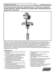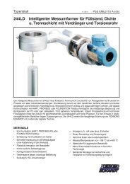
244LVP Intelligent Buoyancy Transmitter for ... - Foxboro Eckardt
244LVP Intelligent Buoyancy Transmitter for ... - Foxboro Eckardt
244LVP Intelligent Buoyancy Transmitter for ... - Foxboro Eckardt

You also want an ePaper? Increase the reach of your titles
YUMPU automatically turns print PDFs into web optimized ePapers that Google loves.
28 <strong>244LVP</strong> MI EML1710 A-(en)<br />
14 SUPPLY OF TRANSMITTER<br />
12.1 General<br />
For safety requirements see chapter 11. Specialties during<br />
operation in explosion protected areas see chapter 11.2..<br />
Depending on the transmitter application varying demands<br />
are made on the supply. The different operating modes are<br />
explained in the following chapters. The wire diagram is<br />
shown in Figures 1 to 5.<br />
The power supply units <strong>for</strong> different applications (direct / via<br />
power supply unit of transmitters, HART / without communication,<br />
intrinsically / not intrinsically) are listed in the<br />
following table.<br />
All listed supply devices are available <strong>for</strong> intrinsically-safe<br />
and/or non-intrinsically-safe application.<br />
Application and asssociated supply<br />
Application<br />
without communication<br />
Supply<br />
(recommended)<br />
direct, MT228, MUS925,<br />
MUS80, MUS924<br />
HART direct, MT228, MUS925<br />
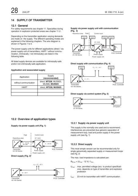
12.2 Overview of application types<br />
Supply via power supply unit (Fig. 1)<br />
Field Control room<br />
Hazardous area MT / MUS<br />
L<br />
<strong>Transmitter</strong><br />
I/A 140 Series<br />
Direct supply (Fig. 2)<br />
L<br />
<strong>Transmitter</strong><br />
I/A 140 Series<br />
4 ... 20 mA<br />
intr. safe<br />
12 ...42 V<br />
U s<br />
Power supply<br />
Power supply unit<br />
= 12 ...42 V<br />
U s<br />
4 ... 20 mA<br />
R L<br />
PCS, Controller<br />
R L<br />
PCS, Controller<br />
Supply via power supply unit with communication<br />
(Fig. 3)<br />
Hazardous area<br />
L<br />
<strong>Transmitter</strong><br />
I/A 140 Series<br />
Direct supply with communication (Fig. 4)<br />
L<br />
<strong>Transmitter</strong><br />
I/A 140 Series<br />
Direct supply via control system (Fig. 5)<br />
L<br />
Communication<br />
4 ... 20 mA<br />
Communication<br />
<strong>Transmitter</strong><br />
I/A 140 Series<br />
12.2.1 Supply via power supply unit<br />
This supply is the normally one used and is recommend.<br />
Interferences are prevented due galvanic separation of<br />
measurement loop, load and power supply in the power<br />
supply unit (see fig. 1)<br />
12.2.2 Direct supply<br />
This most simple version can be recommended only <strong>for</strong><br />
single galvanically separated supply or measurement loops<br />
(see fig. 2)<br />
The max. load impedance is calculated per:<br />
RBmax =(Umax -12V)/Imax<br />
Field Control room<br />
12 ... 42 V<br />
Communication<br />
U s<br />
MT / MUS<br />
Power supply<br />
Power supply unit<br />
= 12 ... 42 V<br />
U s<br />
Communication<br />
4 ... 20 mA<br />
Communication<br />
Communication<br />
Umax: max. permitted voltage (acc. to product specifications),<br />
depends on type of transmitter and explosion<br />
protection<br />
Imax: 23 mA <strong>for</strong> transmitter with HART communication<br />
R L<br />
PCS, Controller<br />
R L<br />
PCS, Controller<br />
e.g.. FBM43 / FBM44<br />
R L<br />
I/A-System