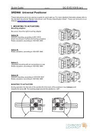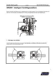
244LVP Intelligent Buoyancy Transmitter for ... - Foxboro Eckardt
244LVP Intelligent Buoyancy Transmitter for ... - Foxboro Eckardt
244LVP Intelligent Buoyancy Transmitter for ... - Foxboro Eckardt

Create successful ePaper yourself
Turn your PDF publications into a flip-book with our unique Google optimized e-Paper software.
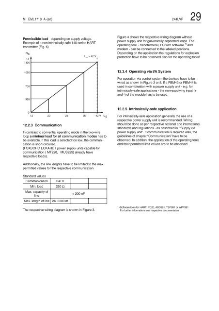
MI EML1710 A-(en) <strong>244LVP</strong> 29<br />
Permissible load depending on supply voltage.<br />
Example of a non intrinsically safe 140 series HART<br />
transmitter (Fig. 6)<br />
4 *<br />
9<br />
!<br />
%<br />
#<br />
! #<br />
12.2.3 Communication<br />
In contrast to convential operating mode in the two-wire<br />
loop a minimal load <strong>for</strong> all communication modes has to<br />
be available. If this load is selected too low, the communication<br />
is short-circuited.<br />
(FOXBORO ECKARDT power supply units capable <strong>for</strong><br />
communication ( MT228, MUS925) already have<br />
respective loads).<br />
Additionally, the line lenghts have to be limited to the max.<br />
permitted values <strong>for</strong> the respective communication<br />
Standard values<br />
Communication HART<br />
Min. load 250 Ω<br />
Max. capacity of<br />
line<br />
Max. length of line ca. 3300 m<br />
< 200 nF<br />
7 � " 8<br />
� = N<br />
& ! $ " 8 7 5<br />
The respective wiring diagram is shown in Figure 3.<br />
Figure 4 shows the respective wiring diagram without<br />
power supply unit <strong>for</strong> galvanically separated loops. The<br />
operating tool - handterminal, PC with software 1) and<br />
modem - can be connected to the labeled positions.<br />
Depending on the application the regulations <strong>for</strong> explosion<br />
protection have to be observed also <strong>for</strong> the operating tools!<br />
12.3.4 Operating via I/A System<br />
For operation via control system the devices have to be<br />
wired as shown in Figure 3 or 5. If a FBM43 or FBM44 is<br />
used in combination with a power supply unit - e.g. <strong>for</strong><br />
intrinsically-safe applications - the non-supplying input (+<br />
and -) of the module has to be used.<br />
12.2.5 Intrinsically-safe application<br />
For intrinsically-safe application generally the use of a<br />
respective power supply unit is recommended. Wiring<br />
should be done as per respective national and international<br />
standards and regulations - as described in “Supply via<br />
power supply unit”. If communication is required also, the<br />
guidelines of chapter “Communication” have to be<br />
observed. In addition, the application of the operating tools<br />
and their permitted limit values are to be observed.<br />
1) Software tools <strong>for</strong> HART: PC20, ABO991, TSP991 or WPP991<br />
For further in<strong>for</strong>mations see respective documentation