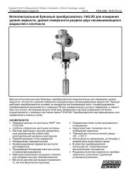
244LVP Intelligent Buoyancy Transmitter for ... - Foxboro Eckardt
244LVP Intelligent Buoyancy Transmitter for ... - Foxboro Eckardt
244LVP Intelligent Buoyancy Transmitter for ... - Foxboro Eckardt

You also want an ePaper? Increase the reach of your titles
YUMPU automatically turns print PDFs into web optimized ePapers that Google loves.
12 <strong>244LVP</strong> MI EML1710 A-(en)<br />
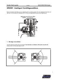
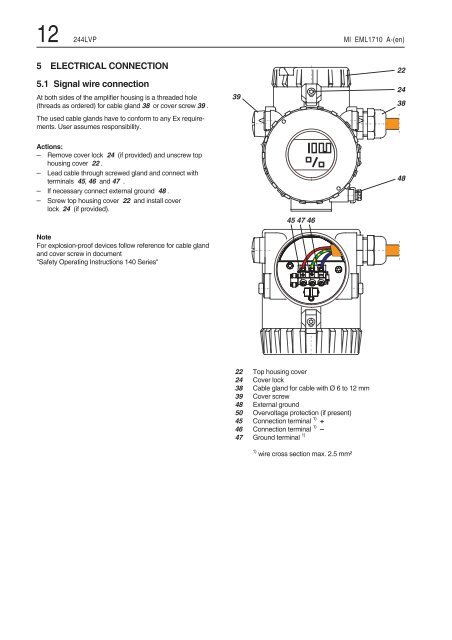
5 ELECTRICAL CONNECTION<br />
5.1 Signal wire connection<br />
At both sides of the amplifier housing is a threaded hole<br />
(threads as ordered) <strong>for</strong> cable gland 38 or cover screw 39 .<br />
The used cable glands have to con<strong>for</strong>m to any Ex requirements.<br />
User assumes responsibility.<br />
Actions:<br />
– Remove cover lock 24 (if provided) and unscrew top<br />
housing cover 22 .<br />
– Lead cable through screwed gland and connect with<br />
terminals 45, 46 and 47 .<br />
– If necessary connect external ground 48 .<br />
– Screw top housing cover 22 and install cover<br />
lock 24 (if provided).<br />
Note<br />
For explosion-proof devices follow reference <strong>for</strong> cable gland<br />
and cover screw in document<br />
"Safety Operating Instructions 140 Series"<br />
! '<br />
" # " % " $<br />
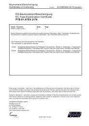
22 Top housing cover<br />
24 Cover lock<br />
38 Cable gland <strong>for</strong> cable with Ø 6 to 12 mm<br />
39 Cover screw<br />
48 External ground<br />
50 Overvoltage protection (if present)<br />
45 Connection terminal 1) +<br />
46 Connection terminal 1) –<br />
47 Ground terminal 1)<br />
1) wire cross section max. 2.5 mm²<br />
"<br />
! &<br />
" &